EP3406881B1 - Steuerung eines verdichters eines gasturbinenmotors - Google Patents
Steuerung eines verdichters eines gasturbinenmotors Download PDFInfo
- Publication number
- EP3406881B1 EP3406881B1 EP17425052.2A EP17425052A EP3406881B1 EP 3406881 B1 EP3406881 B1 EP 3406881B1 EP 17425052 A EP17425052 A EP 17425052A EP 3406881 B1 EP3406881 B1 EP 3406881B1
- Authority
- EP
- European Patent Office
- Prior art keywords
- bleed air
- compressor
- engine
- ecs
- line
- Prior art date
- Legal status (The legal status is an assumption and is not a legal conclusion. Google has not performed a legal analysis and makes no representation as to the accuracy of the status listed.)
- Active
Links
Images



Classifications
-
- F—MECHANICAL ENGINEERING; LIGHTING; HEATING; WEAPONS; BLASTING
- F02—COMBUSTION ENGINES; HOT-GAS OR COMBUSTION-PRODUCT ENGINE PLANTS
- F02C—GAS-TURBINE PLANTS; AIR INTAKES FOR JET-PROPULSION PLANTS; CONTROLLING FUEL SUPPLY IN AIR-BREATHING JET-PROPULSION PLANTS
- F02C9/00—Controlling gas-turbine plants; Controlling fuel supply in air- breathing jet-propulsion plants
-
- F—MECHANICAL ENGINEERING; LIGHTING; HEATING; WEAPONS; BLASTING
- F02—COMBUSTION ENGINES; HOT-GAS OR COMBUSTION-PRODUCT ENGINE PLANTS
- F02C—GAS-TURBINE PLANTS; AIR INTAKES FOR JET-PROPULSION PLANTS; CONTROLLING FUEL SUPPLY IN AIR-BREATHING JET-PROPULSION PLANTS
- F02C9/00—Controlling gas-turbine plants; Controlling fuel supply in air- breathing jet-propulsion plants
- F02C9/16—Control of working fluid flow
- F02C9/18—Control of working fluid flow by bleeding, bypassing or acting on variable working fluid interconnections between turbines or compressors or their stages
-
- F—MECHANICAL ENGINEERING; LIGHTING; HEATING; WEAPONS; BLASTING
- F02—COMBUSTION ENGINES; HOT-GAS OR COMBUSTION-PRODUCT ENGINE PLANTS
- F02C—GAS-TURBINE PLANTS; AIR INTAKES FOR JET-PROPULSION PLANTS; CONTROLLING FUEL SUPPLY IN AIR-BREATHING JET-PROPULSION PLANTS
- F02C6/00—Plural gas-turbine plants; Combinations of gas-turbine plants with other apparatus; Adaptations of gas-turbine plants for special use
- F02C6/04—Gas-turbine plants providing heated or pressurised working fluid for other apparatus, e.g. without mechanical power output
- F02C6/06—Gas-turbine plants providing heated or pressurised working fluid for other apparatus, e.g. without mechanical power output providing compressed gas
- F02C6/08—Gas-turbine plants providing heated or pressurised working fluid for other apparatus, e.g. without mechanical power output providing compressed gas the gas being bled from the gas-turbine compressor
-
- F—MECHANICAL ENGINEERING; LIGHTING; HEATING; WEAPONS; BLASTING
- F04—POSITIVE - DISPLACEMENT MACHINES FOR LIQUIDS; PUMPS FOR LIQUIDS OR ELASTIC FLUIDS
- F04D—NON-POSITIVE-DISPLACEMENT PUMPS
- F04D27/00—Control, e.g. regulation, of pumps, pumping installations or pumping systems specially adapted for elastic fluids
-
- F—MECHANICAL ENGINEERING; LIGHTING; HEATING; WEAPONS; BLASTING
- F04—POSITIVE - DISPLACEMENT MACHINES FOR LIQUIDS; PUMPS FOR LIQUIDS OR ELASTIC FLUIDS
- F04D—NON-POSITIVE-DISPLACEMENT PUMPS
- F04D27/00—Control, e.g. regulation, of pumps, pumping installations or pumping systems specially adapted for elastic fluids
- F04D27/02—Surge control
-
- F—MECHANICAL ENGINEERING; LIGHTING; HEATING; WEAPONS; BLASTING
- F04—POSITIVE - DISPLACEMENT MACHINES FOR LIQUIDS; PUMPS FOR LIQUIDS OR ELASTIC FLUIDS
- F04D—NON-POSITIVE-DISPLACEMENT PUMPS
- F04D27/00—Control, e.g. regulation, of pumps, pumping installations or pumping systems specially adapted for elastic fluids
- F04D27/02—Surge control
- F04D27/0207—Surge control by bleeding, bypassing or recycling fluids
- F04D27/0215—Arrangements therefor, e.g. bleed or by-pass valves
-
- F—MECHANICAL ENGINEERING; LIGHTING; HEATING; WEAPONS; BLASTING
- F05—INDEXING SCHEMES RELATING TO ENGINES OR PUMPS IN VARIOUS SUBCLASSES OF CLASSES F01-F04
- F05D—INDEXING SCHEME FOR ASPECTS RELATING TO NON-POSITIVE-DISPLACEMENT MACHINES OR ENGINES, GAS-TURBINES OR JET-PROPULSION PLANTS
- F05D2220/00—Application
- F05D2220/30—Application in turbines
- F05D2220/32—Application in turbines in gas turbines
- F05D2220/323—Application in turbines in gas turbines for aircraft propulsion, e.g. jet engines
-
- F—MECHANICAL ENGINEERING; LIGHTING; HEATING; WEAPONS; BLASTING
- F05—INDEXING SCHEMES RELATING TO ENGINES OR PUMPS IN VARIOUS SUBCLASSES OF CLASSES F01-F04
- F05D—INDEXING SCHEME FOR ASPECTS RELATING TO NON-POSITIVE-DISPLACEMENT MACHINES OR ENGINES, GAS-TURBINES OR JET-PROPULSION PLANTS
- F05D2260/00—Function
- F05D2260/60—Fluid transfer
- F05D2260/606—Bypassing the fluid
-
- F—MECHANICAL ENGINEERING; LIGHTING; HEATING; WEAPONS; BLASTING
- F05—INDEXING SCHEMES RELATING TO ENGINES OR PUMPS IN VARIOUS SUBCLASSES OF CLASSES F01-F04
- F05D—INDEXING SCHEME FOR ASPECTS RELATING TO NON-POSITIVE-DISPLACEMENT MACHINES OR ENGINES, GAS-TURBINES OR JET-PROPULSION PLANTS
- F05D2270/00—Control
- F05D2270/01—Purpose of the control system
- F05D2270/10—Purpose of the control system to cope with, or avoid, compressor flow instabilities
- F05D2270/101—Compressor surge or stall
-
- F—MECHANICAL ENGINEERING; LIGHTING; HEATING; WEAPONS; BLASTING
- F05—INDEXING SCHEMES RELATING TO ENGINES OR PUMPS IN VARIOUS SUBCLASSES OF CLASSES F01-F04
- F05D—INDEXING SCHEME FOR ASPECTS RELATING TO NON-POSITIVE-DISPLACEMENT MACHINES OR ENGINES, GAS-TURBINES OR JET-PROPULSION PLANTS
- F05D2270/00—Control
- F05D2270/30—Control parameters, e.g. input parameters
-
- Y—GENERAL TAGGING OF NEW TECHNOLOGICAL DEVELOPMENTS; GENERAL TAGGING OF CROSS-SECTIONAL TECHNOLOGIES SPANNING OVER SEVERAL SECTIONS OF THE IPC; TECHNICAL SUBJECTS COVERED BY FORMER USPC CROSS-REFERENCE ART COLLECTIONS [XRACs] AND DIGESTS
- Y02—TECHNOLOGIES OR APPLICATIONS FOR MITIGATION OR ADAPTATION AGAINST CLIMATE CHANGE
- Y02T—CLIMATE CHANGE MITIGATION TECHNOLOGIES RELATED TO TRANSPORTATION
- Y02T50/00—Aeronautics or air transport
- Y02T50/50—On board measures aiming to increase energy efficiency
Definitions
- Turbine engines and particularly gas or combustion turbine engines, are rotary engines that extract energy from a flow of pressurized combusted gases passing through the engine onto a multitude of rotating turbine blades.
- Gas turbine engines for aircraft can be designed to operate with pre-selected pressure ratios. Optimizing the pressure ratio can be beneficial for the engine efficiency and output power.
- EP 2 955 334 A1 discloses a method comprising: determining an operating point of the compressor, and modulating mass flow of environmental control system input air to maintain the operating point of the gas turbine engine compressor within predetermined limits.
- US 2002/0170295 A1 discloses a method and a system for reducing aircraft engine fuel consumption by selectively closing an aircraft surge bleed valve (SBV), when the surge bleed valve would normally be open.
- SBV surge bleed valve
- a method of real-time controlling of a compressor of a turbine engine according to claim 1 is provided.
- an aircraft according to claim 8 is provided.
- the described embodiments of the present disclosure are directed to systems, methods, and other devices related to a stall margin of a compressor.
- the present disclosure will be described with respect to an aircraft gas turbine engine. It will be understood, however, that the disclosure is not so limited and may have general applicability in non-aircraft applications, such as other land based or marine mobile applications, non-mobile industrial, military, commercial, and residential applications.
- forward or “upstream” refers to moving in a direction toward the engine inlet, or a component being relatively closer to the engine inlet as compared to another component.
- downstream used in conjunction with “forward” or “upstream” refers to a direction toward the rear or outlet of the engine or being relatively closer to the engine outlet as compared to another component.
- radial refers to a dimension extending between a center longitudinal axis of the engine and an outer engine circumference.
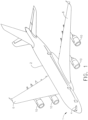
- FIG. 1 illustrates an aircraft 1 which can also include a fuselage 2, a cockpit 4 positioned in the fuselage 2, and wing assemblies 6 extending outward from the fuselage 2.
- the aircraft 1 can also include multiple engines, including turbine engines 10 which by way of non-limiting example can be turbojet, turbofan, turboprop, or turboshaft engines. While a commercial fixed wing aircraft 1 has been illustrated, it is contemplated that aspects of the disclosure described herein can be used in any type of fixed wing, rotary wing, or convertible wing aircraft such as the V22 Osprey in a non-limiting example.
- turbine engines 10 have been illustrated on each of the wing assemblies 6, it will be understood that any number of turbine engines 10 including a single turbine engine 10 on the wing assemblies 6, or even a single turbine engine 10 mounted in the fuselage 2 can be included.
- the aircraft 1 includes a rotary wing aircraft
- multiple fuselage mounted turbine engines can be included in the aircraft 1.
- the turbine engine 10 has a generally longitudinally extending axis or centerline 12 extending forward 14 to aft 16.
- the engine 10 includes, in downstream serial flow relationship, a fan section 18 including a fan 20, a compressor section 22 including a booster or low pressure (LP) compressor 24 and a high pressure (HP) compressor 26, a combustion section 28 including a combustor 30, a turbine section 32 including a HP turbine 34, and a LP turbine 36, and an exhaust section 38.
- LP booster or low pressure
- HP high pressure
- the fan section 18 includes a fan casing 40 surrounding the fan 20.
- the fan 20 includes a plurality of fan blades 42 disposed radially about the centerline 12.
- the HP compressor 26, the combustor 30, and the HP turbine 34 form a core 44 of the engine 10, which generates combustion gases.
- the core 44 is surrounded by core casing 46, which can be coupled with the fan casing 40.
- a LP shaft or spool 50 which is disposed coaxially about the centerline 12 of the engine 10 within the larger diameter annular HP spool 48, drivingly connects the LP turbine 36 to the LP compressor 24 and fan 20.
- the spools 48, 50 are rotatable about the engine centerline and couple to a plurality of rotatable elements, which can collectively define a rotor 51.
- the LP compressor 24 and the HP compressor 26 respectively include a plurality of compressor stages 52, 54, in which a set of compressor blades 56, 58 rotate relative to a corresponding set of static compressor vanes 60, 62 to compress or pressurize the stream of fluid passing through the stage.
- a single compressor stage 52, 54 multiple compressor blades 56, 58 can be provided in a ring and can extend radially outwardly relative to the centerline 12, from a blade platform to a blade tip, while the corresponding static compressor vanes 60, 62 are positioned upstream of and adjacent to the rotating blades 56, 58. It is noted that the number of blades, vanes, and compressor stages shown in FIG. 1 were selected for illustrative purposes only, and that other numbers are possible.
- the blades 56, 58 for a stage of the compressor can be mounted to (or integral to) a disk 61, which is mounted to the corresponding one of the HP and LP spools 48, 50.
- the vanes 60, 62 for a stage of the compressor can be mounted to the core casing 46 in a circumferential arrangement.
- the HP turbine 34 and the LP turbine 36 respectively include a plurality of turbine stages 64, 66, in which a set of turbine blades 68, 70 are rotated relative to a corresponding set of static turbine vanes 72, 74 (also called a nozzle) to extract energy from the stream of fluid passing through the stage.
- a single turbine stage 64, 66 multiple turbine blades 68, 70 can be provided in a ring and can extend radially outwardly relative to the centerline 12 while the corresponding static turbine vanes 72, 74 are positioned upstream of and adjacent to the rotating blades 68, 70. It is noted that the number of blades, vanes, and turbine stages shown in FIG. 1 were selected for illustrative purposes only, and that other numbers are possible.
- the blades 68, 70 for a stage of the turbine can be mounted to a disk 71, which is mounted to the corresponding one of the HP and LP spools 48, 50.
- the vanes 72, 74 for a stage of the compressor can be mounted to the core casing 46 in a circumferential arrangement.
- stator 63 can refer to the combination of non-rotating elements throughout the engine 10.
- the airflow exiting the fan section 18 is split such that a portion of the airflow is channeled into the LP compressor 24, which then supplies pressurized air 76 to the HP compressor 26, which further pressurizes the air.
- the pressurized air 76 from the HP compressor 26 is mixed with fuel in the combustor 30 and ignited, thereby generating combustion gases. Some work is extracted from these gases by the HP turbine 34, which drives the HP compressor 26.
- the combustion gases are discharged into the LP turbine 36, which extracts additional work to drive the LP compressor 24, and the exhaust gas is ultimately discharged from the engine 10 via the exhaust section 38.
- the driving of the LP turbine 36 drives the LP spool 50 to rotate the fan 20 and the LP compressor 24.
- a portion of the pressurized airflow 76 can be drawn from the compressor section 22 as bleed air 77.
- the bleed air 77 can be drawn from the pressurized airflow 76 and provided to engine components requiring cooling.
- the temperature of pressurized airflow 76 entering the combustor 30 is significantly increased. As such, cooling provided by the bleed air 77 is necessary for operating of such engine components in the heightened temperature environments.
- a remaining portion of the airflow 78 bypasses the LP compressor 24 and engine core 44 and exits the engine assembly 10 through a stationary vane row, and more particularly an outlet guide vane assembly 80, comprising a plurality of airfoil guide vanes 82, at the fan exhaust side 84. More specifically, a circumferential row of radially extending airfoil guide vanes 82 are utilized adjacent the fan section 18 to exert some directional control of the airflow 78.
- Some of the air supplied by the fan 20 can bypass the engine core 44 and be used for cooling of portions, especially hot portions, of the engine 10, and/or used to cool or power other aspects of the aircraft 1.
- the hot portions of the engine are normally downstream of the combustor 30, especially the turbine section 32, with the HP turbine 34 being the hottest portion as it is directly downstream of the combustion section 28.
- Other sources of cooling fluid can be, but are not limited to, fluid discharged from the LP compressor 24 or the HP compressor 26.
- the compressor section 22 can include an LP bleed air line 92 fluidly connected to the stage 52 of the LP compressor 24, and an HP bleed air line 94 fluidly connected to the stage 54 of the HP compressor 26.
- An LP dump valve 96 can be coupled to the LP bleed air line 92, and an HP dump valve 98 can be coupled to the HP bleed air line 94 as shown, where the dump valves 96, 98 can be fluidly connected to atmosphere external to the aircraft 1 ( FIG. 1 ).
- the stages 52, 54 to which the bleed air lines 92, 94 are connected are exemplary and can be any stages within the LP compressor 24 and HP compressor 26, respectively.
- the aircraft 1 ( FIG. 1 ) further comprises an environmental control system (ECS) 100 and ECS sensors 102, which can be positioned anywhere within the engine 10 and are illustrated in FIG. 3 as positioned at the stages 52, 54 of the compressors 24, 26. It will be understood that the ECS 100 can manage cabin air supply as well as other factors, such as air pressurization or temperature, in non-limiting examples.
- ECS environmental control system
- the sensors 102 can sense an engine operating parameter including, but not limited to, engine horsepower, engine horsepower extraction, environmental control system bleed, foreign object debris door deployment, or a secondary engine parameter including, but not limited to, engine age, transient effects, temperature effects, minimum airspeed, altitude, attitude, engine inlet distortion, or inclement weather conditions, and it should be appreciated that the sensed parameters also indicate a demand for the use of bleed air from the compressors 24, 26. It will be understood that at least one of the above-listed parameters may be sensed by the sensors 102, or at least four, or all of the parameters, or any desired combination, in non-limiting examples. It will further be understood that other aircraft or engine parameters which can impact operability of the aircraft 1 may also be sensed by the sensors 102.
- An engine controller 110 (which can be a full authority digital engine controller, or "FADEC”) is also included in the turbine engine 10.
- An ECS signal 104 communicating the sensed parameter is sent from the sensors 102 to the controller 110, and a controller signal 111 can be sent from the controller 110 to the dump valves 96, 98 or to other components (not shown) of the engine in operation.
- the engine controller 110 includes a memory 112.
- a compressor map 114 which is used by the controller 110 to operate the engine 10 is stored in the memory 112, and the compressor map 114 can include a surge line 116, operating line 118, and stall margin 120.
- surge line will refer to the pressure ratio wherein the airflow through the engine 10 can break down or become unstable, causing an engine stall
- operating line will refer to the operating pressure ratio which can be below that of the surge line.
- pressure ratio can refer to any of the following in non-limiting examples: the ratio of air pressures taken at the inlet and outlet of the compressor section 22, the ratio of air pressures taken at the inlet and outlet of the compressors 24, 26 individually, or the ratio of air pressures taken at any two locations within the compressor section 22 as desired such as the P25 or P3 locations.
- the stall margin 120 can be defined as the difference between the surge line 116 and operating line 118, and it should be understood that the percent difference between the surge line 116 and operating line 118 can also be used to define the stall margin 120.
- the operating line was set based on a fixed-value, maximum safety factor stall margin, which assumed worst case operating conditions for the aircraft and which led to a corresponding large stall margin. All things being equal, the greater the stall margin, the less efficiently the engine is operating.
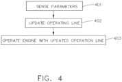
- a method of controlling the compressors 24, 26 for operating the engine 10 is illustrated in FIG. 4 .
- the sensors 102 can sense the desired engine or secondary parameter during operation of the engine 10 as described above.
- the ECS signal 104 can be directed to the engine controller 110, where a processor within the controller 110 can receive the ECS signal 104 and update the compressor map 114 in real time.
- SM 100 % PR s ⁇ PR o PR o
- PR s the pressure ratio at the surge line 116
- PR o the pressure ratio at the operating line 118
- the calculation may differ from that given here, and that the stall margin 120 can depend on pressure ratios, air temperatures, coefficients of heat transfer, and other parameters that can be sensed by the sensors 102.
- a new operating line 118 can be calculated by the controller 110 in real time at step 402.
- the engine controller 110 can operate the engine 10 according to the updated compressor map 114 at step 403.
- the stall margin 120 based on the real-time-updated operating line 118 can be less than a maximum safety factor stall margin for the turbine engine 10, and it is further contemplated that one result of operating the engine 10 based on the updated operating line 118 can be to dump bleed air from either or both of the bleed air lines 92, 94.
- the steps outlined in FIG. 4 can be repeated during the operation of the engine 10; in non-limiting examples the repetition of steps 401, 402, 403 can occur on a predetermined schedule, at predetermined time intervals, at predetermined schedules at predetermined time intervals, or during predetermined phases of operation such as take-off, climb, cruise, descent, or landing.
- bleed air can be used to drive components within the engine 10 or for cooling purposes, in non-limiting examples, and a method of controlling the compressors 24, 26 for directing bleed air is illustrated in FIG. 5 .
- the sensors 102 can sense in real time the desired engine or secondary parameter as described above where the parameter can indicate a demand for ECS bleed air.
- the controller and the ECS signal 104 can be sent to the controller 110, and at step 502 the demand for bleed air can be checked. If such a demand is sensed, the controller 110 can send the controller signal 111 to the dump valves 96, 98 to be closed (or stay closed as appropriate) in step 503A to keep the air in the bleed air lines 92, 94.
- the controller signal 111 can direct either or both of the dump valves 96, 98 to be opened (or stay open as appropriate) in step 503B to dump the bleed air to the external atmosphere.
- a lower-than-expected demand for bleed air can indicate a fault condition within the engine 10, or pose a risk to the operating line of the compressor 24, 26, and in such a case, dumping bleed air can be a way to maintain the stall margin 120.
- the condition of "no demand" can include a bleed air demand threshold level, below which the controller 110 can determine that the bleed air should be dumped.
- bleed air from one location in the compressor 24, 26, can be prioritized over that from another location in the compressor 24, 26 as desired; in non-limiting examples, bleed air at the P25 location in the HP compressor 26 can be prioritized over that of P3 location at cruising altitude, or a chosen dump valve can be instructed to never open unless the ECS 100 is turned off.
- An additional engine parameter such as aircraft horsepower extraction or foreign object door (FOD) deployment in non-limiting examples, can also be checked along with the demand for bleed air; it can be appreciated that the operating line 118 can be updated in real time by the combination of the additional parameter and the sensed demand for bleed air. It will be understood that the steps outlined in FIG. 5 can also be repeated during engine operation, and that such repetition can occur on a predetermined schedule or at predetermined time intervals as desired.
- a signal can be sent to the aircraft 1 to cause a change to the aircraft to maintain a positive stall margin 120.
- changes to the aircraft include reduction of horsepower extraction load, change in FOD door state (for example, from 'deployed' to 'stowed'), or increase in bleed air flow (for example, from a 'nominal' to 'high' flow rate).
- the signal can include any parameter appropriate for a variety of aircraft types, and it can be appreciated that the capability for engine signaling features can be significantly expanded in an example where the aircraft 1 includes a remotely-piloted or autonomous aircraft as the engine controller 110 and an aircraft controller can have enhanced authority over operating features of the aircraft 1.
- updating the operating line 118 and stall margin 120 in real time ( FIG. 3 , FIG. 4 ), and the selective removal of bleed air from the engine 10 ( FIG. 3 , FIG. 5 ), can provide for an optimization of engine performance and efficiency compared to that based on a traditional, maximum safety factor stall margin.
- the traditional stall margin based on worst-case operating conditions can have a maximized safety factor to prevent a stall condition; however, the "worst-case operating conditions" generally assumed that every contributing factor toward a stall condition would happen simultaneously.
- the real-time-updated operating line 118 can be above that based on the maximum safety factor stall margin, leading to an optimized performance level and engine efficiency, but still remain below the surge line 116 at which point an engine stall could result.
- the real-time parameter sensing by the ECS sensors 102 can provide for active management of the environmental control system 100 or operation of the engine 10, including dumping the bleed air as appropriate.
Landscapes
- Engineering & Computer Science (AREA)
- Mechanical Engineering (AREA)
- General Engineering & Computer Science (AREA)
- Chemical & Material Sciences (AREA)
- Combustion & Propulsion (AREA)
- Physics & Mathematics (AREA)
- Fluid Mechanics (AREA)
- Life Sciences & Earth Sciences (AREA)
- Sustainable Development (AREA)
- Structures Of Non-Positive Displacement Pumps (AREA)
- Combined Controls Of Internal Combustion Engines (AREA)
Claims (11)
- Verfahren zum Echtzeitsteuern eines Verdichters (22) eines Turbinentriebwerks (10), das eine Steuerung (110) aufweist, in der ein Verdichterkennfeld (114), einschließlich einer Pumplinie (116) und einer Betriebslinie (118), gespeichert ist, wobei die Differenz dazwischen eine Strömungsabrissgrenze (120) definiert, das Verfahren umfassend:während des Betriebs des Motors (10), Erfassen eines Bedarfs für Umgebungssteuersystemzapfluft (77) in Echtzeit; undAblassen von Umgebungssteuersystemzapfluft (77) von dem Verdichter (22), durch ein Ablassventil (96, 98), in die Atmosphäre, wenn der erfasste Bedarf keinen Bedarf angibt.
- Verfahren nach Anspruch 1, ferner umfassend ein Steuern des Ablassens der Umgebungssteuersystemzapfluft (77), um eine Echtzeitbetriebslinie (118) unter der Pumplinie (116) aufrechtzuerhalten.
- Verfahren nach Anspruch 2, ferner umfassend das Erfassen eines Triebwerkparameters in Echtzeit mit Ausnahme von der Umgebungssteuersystemzapfluft und Verwenden des Triebwerkparameters in Kombination mit dem Bedarf für Umgebungssteuersystemzapfluft, um eine Echtzeitbetriebslinie einzustellen.
- Verfahren nach Anspruch 3, wobei der Triebwerkparameter einer Fremdkörpertürentfaltung oder einer Pferdestärkenextraktion entspricht.
- Verfahren nach Anspruch 3, wobei die Echtzeitbetriebslinie (118) eine Echtzeitströmungsabrissgrenze (120), die kleiner als eine maximale Sicherheitsfaktorströmungsabrissgrenze (120) ist, definiert.
- Verfahren nach Anspruch 3, wobei der Triebwerkparameter mindestens eines umfasst von: Pferdestärken, Fremdkörpertürentfaltung, Triebwerkalter, Übergangseffekten, Temperatureffekten, minimaler Luftgeschwindigkeit, Höhe, Lage, Einlassverzerrung oder rauen Wetterbedingungen.
- Verfahren nach Anspruch 1, wobei das Abstoßen von Umgebungssteuersystemzapfluft ein Öffnen eines Entlüftungsventils (96, 98), das mit einer Zapfluftleitung (92) von dem Verdichter zu einem Umgebungssteuersystem fluidisch gekoppelt ist, umfasst.
- Luftfahrzeug, umfassend:ein Umweltsteuersystem (100), ECS;ein Turbinentriebwerk (10), umfassend einen Mehrstufenverdichter (22) mit einer Zapfluftleitung (92, 94), die mindestens eine der mehreren Stufen (52, 54) mit dem ECS (10) fluidisch koppelt, und ein Ablassventil (96, 98), das die Zapfluftleitung (92, 94) mit der Atmosphäre fluidisch koppelt;einen ECS-Sensor (102), der mit mindestens einem von dem ECS (100) und der Zapfluftleitung (77) betriebsfähig gekoppelt ist und ein ECS-Signal ausgibt, das einen Bedarf für das ECS angibt; undeine Steuerung (110), die das ECS-Signal empfängt und mit dem Ablassventil (96, 98) betriebsfähig gekoppelt ist und das Ablassventil (96, 98) öffnet, wenn das ECS-Signal keinen Bedarf durch das ECS (100) für Zapfluft (77) angibt.
- Luftfahrzeug nach Anspruch 8, wobei der Verdichter (22) einen Hochdruckverdichter (26) und einen Niederdruckverdichter (24) umfasst und die Zapfluftleitung (92) eine Hochdruckzapfluftleitung (94), die mit dem Hochdruckverdichter (26) fluidisch gekoppelt ist, und eine Niederdruckzapfluftleitung (92), die mit dem Niederdruckverdichter (24) fluidisch gekoppelt ist, umfasst.
- Luftfahrzeug nach Anspruch 9, wobei das Ablassventil (96, 98) mit mindestens einer von der Hochdruckzapfluftleitung (94) und der Niederdruckzapfluftleitung (92) fluidisch gekoppelt ist.
- Luftfahrzeug nach Anspruch 10, wobei das Ablassventil ein Hochdruckablassventil (98), das mit der Hochdruckzapfluftleitung (94) fluidisch gekoppelt ist, und ein Niederdruckablass (96), das mit der Niederdruckzapfluftleitung (92) fluidisch gekoppelt ist, umfasst.
Priority Applications (7)
| Application Number | Priority Date | Filing Date | Title |
|---|---|---|---|
| EP17425052.2A EP3406881B1 (de) | 2017-05-25 | 2017-05-25 | Steuerung eines verdichters eines gasturbinenmotors |
| EP23152323.4A EP4194676A1 (de) | 2017-05-25 | 2017-05-25 | Steuerung eines verdichters eines turbinenmotors |
| CA3004552A CA3004552C (en) | 2017-05-25 | 2018-05-10 | Controlling a compressor of a turbine engine |
| US15/978,097 US12123359B2 (en) | 2017-05-25 | 2018-05-12 | Controlling a compressor of a turbine engine |
| CN201810514245.4A CN108952971A (zh) | 2017-05-25 | 2018-05-25 | 控制涡轮发动机的压缩机 |
| CN202110181806.5A CN112879166B (zh) | 2017-05-25 | 2018-05-25 | 控制涡轮发动机的压缩机 |
| US18/920,146 US20260117709A1 (en) | 2017-05-25 | 2024-10-18 | Controlling a compressor of a turbine engine |
Applications Claiming Priority (1)
| Application Number | Priority Date | Filing Date | Title |
|---|---|---|---|
| EP17425052.2A EP3406881B1 (de) | 2017-05-25 | 2017-05-25 | Steuerung eines verdichters eines gasturbinenmotors |
Related Child Applications (2)
| Application Number | Title | Priority Date | Filing Date |
|---|---|---|---|
| EP23152323.4A Division-Into EP4194676A1 (de) | 2017-05-25 | 2017-05-25 | Steuerung eines verdichters eines turbinenmotors |
| EP23152323.4A Division EP4194676A1 (de) | 2017-05-25 | 2017-05-25 | Steuerung eines verdichters eines turbinenmotors |
Publications (2)
| Publication Number | Publication Date |
|---|---|
| EP3406881A1 EP3406881A1 (de) | 2018-11-28 |
| EP3406881B1 true EP3406881B1 (de) | 2023-03-08 |
Family
ID=59325252
Family Applications (2)
| Application Number | Title | Priority Date | Filing Date |
|---|---|---|---|
| EP17425052.2A Active EP3406881B1 (de) | 2017-05-25 | 2017-05-25 | Steuerung eines verdichters eines gasturbinenmotors |
| EP23152323.4A Pending EP4194676A1 (de) | 2017-05-25 | 2017-05-25 | Steuerung eines verdichters eines turbinenmotors |
Family Applications After (1)
| Application Number | Title | Priority Date | Filing Date |
|---|---|---|---|
| EP23152323.4A Pending EP4194676A1 (de) | 2017-05-25 | 2017-05-25 | Steuerung eines verdichters eines turbinenmotors |
Country Status (4)
| Country | Link |
|---|---|
| US (2) | US12123359B2 (de) |
| EP (2) | EP3406881B1 (de) |
| CN (2) | CN112879166B (de) |
| CA (1) | CA3004552C (de) |
Families Citing this family (14)
| Publication number | Priority date | Publication date | Assignee | Title |
|---|---|---|---|---|
| FR3063782B1 (fr) * | 2017-03-07 | 2021-06-18 | Safran Aircraft Engines | Procede et dispositif de detection de conditions propices a l'apparition d'un pompage en vue de proteger un compresseur d'une turbomachine d'aeronef |
| EP3406881B1 (de) * | 2017-05-25 | 2023-03-08 | Ge Avio S.r.l. | Steuerung eines verdichters eines gasturbinenmotors |
| GB201720944D0 (en) * | 2017-12-15 | 2018-01-31 | Rolls Royce Plc | Rotor bow management |
| GB201808436D0 (en) * | 2018-05-23 | 2018-07-11 | Rolls Royce Plc | Gas turbine engine compressor control method |
| US20210016888A1 (en) * | 2019-07-15 | 2021-01-21 | United Technologies Corporation | Modulated combustor bypass for hybrid idle |
| US20220097864A1 (en) | 2020-09-30 | 2022-03-31 | Ge Avio S.R.L. | Aircraft performance optimization based on engine performance monitoring |
| CN112937885B (zh) * | 2021-03-04 | 2023-04-14 | 中国商用飞机有限责任公司 | 一种利用辅助动力装置进行引气的引气系统以及引气控制方法 |
| US11448126B1 (en) * | 2021-06-07 | 2022-09-20 | Rohr, Inc. | Dual-pressure source aircraft pneumatic system with pressure relief |
| US11802509B2 (en) | 2021-06-25 | 2023-10-31 | Pratt & Whitney Canada Corp. | Air filtration system and method for compressor bleed valve |
| US11852073B2 (en) | 2021-07-30 | 2023-12-26 | Pratt & Whitney Canada Corp. | Orifice pack for compressor bleed valve |
| US11639689B2 (en) * | 2021-09-17 | 2023-05-02 | Pratt & Whitney Canada Corp. | Intake device for gas turbine engine |
| CN116085067B (zh) | 2021-11-05 | 2026-05-29 | 通用电气公司 | 具有流体导管系统的燃气涡轮发动机及其操作方法 |
| US11859500B2 (en) * | 2021-11-05 | 2024-01-02 | General Electric Company | Gas turbine engine with a fluid conduit system and a method of operating the same |
| GB2626331B (en) * | 2023-01-18 | 2025-03-26 | Rolls Royce Plc | Method of controlling a gas turbine engine |
Family Cites Families (22)
| Publication number | Priority date | Publication date | Assignee | Title |
|---|---|---|---|---|
| US4380893A (en) | 1981-02-19 | 1983-04-26 | The Garrett Corporation | Compressor bleed air control apparatus and method |
| US6059522A (en) | 1996-04-17 | 2000-05-09 | United Technologies Corporation | Compressor stall diagnostics and avoidance |
| US6364602B1 (en) | 2000-01-06 | 2002-04-02 | General Electric Company | Method of air-flow measurement and active operating limit line management for compressor surge avoidance |
| US6506010B1 (en) | 2001-04-17 | 2003-01-14 | General Electric Company | Method and apparatus for compressor control and operation in industrial gas turbines using stall precursors |
| US6481210B1 (en) * | 2001-05-16 | 2002-11-19 | Honeywell International, Inc. | Smart surge bleed valve system and method |
| US6438484B1 (en) * | 2001-05-23 | 2002-08-20 | General Electric Company | Method and apparatus for detecting and compensating for compressor surge in a gas turbine using remote monitoring and diagnostics |
| US7219040B2 (en) | 2002-11-05 | 2007-05-15 | General Electric Company | Method and system for model based control of heavy duty gas turbine |
| GB0523337D0 (en) | 2005-11-16 | 2005-12-28 | Rolls Royce Plc | Engine arrangements and control |
| EP1847715A1 (de) * | 2006-04-19 | 2007-10-24 | Siemens Aktiengesellschaft | Verfahren zum Betreiben eines Turboverdichters sowie Turboverdichter |
| US7827803B1 (en) | 2006-09-27 | 2010-11-09 | General Electric Company | Method and apparatus for an aerodynamic stability management system |
| US7908115B2 (en) | 2007-10-09 | 2011-03-15 | University Of Notre Dame Du Lac | Plasma sensors and related methods |
| US8036844B2 (en) | 2008-03-24 | 2011-10-11 | Honeywell International Inc. | Transient performance data phase compensation system and method |
| US8322145B2 (en) * | 2009-04-23 | 2012-12-04 | General Electric Company | Systems and methods for providing surge protection to a turbine component |
| GB0915616D0 (en) | 2009-09-08 | 2009-10-07 | Rolls Royce Plc | Surge margin regulation |
| US8967528B2 (en) * | 2012-01-24 | 2015-03-03 | The Boeing Company | Bleed air systems for use with aircrafts and related methods |
| US9097133B2 (en) | 2012-06-04 | 2015-08-04 | United Technologies Corporation | Compressor tip clearance management for a gas turbine engine |
| US9540944B2 (en) * | 2012-09-28 | 2017-01-10 | United Technologies Corporation | Real time model based compressor control |
| GB201319563D0 (en) * | 2013-11-06 | 2013-12-18 | Rolls Royce Plc | Pneumatic system for an aircraft |
| US9810158B2 (en) * | 2014-04-01 | 2017-11-07 | The Boeing Company | Bleed air systems for use with aircraft and related methods |
| GB201410180D0 (en) * | 2014-06-09 | 2014-07-23 | Rolls Royce Plc | Method and apparatus for controlling a compressor of a gas turbine engine |
| US10421551B2 (en) | 2014-12-15 | 2019-09-24 | United Technologies Corporation | Aircraft anti-icing system |
| EP3406881B1 (de) * | 2017-05-25 | 2023-03-08 | Ge Avio S.r.l. | Steuerung eines verdichters eines gasturbinenmotors |
-
2017
- 2017-05-25 EP EP17425052.2A patent/EP3406881B1/de active Active
- 2017-05-25 EP EP23152323.4A patent/EP4194676A1/de active Pending
-
2018
- 2018-05-10 CA CA3004552A patent/CA3004552C/en active Active
- 2018-05-12 US US15/978,097 patent/US12123359B2/en active Active
- 2018-05-25 CN CN202110181806.5A patent/CN112879166B/zh active Active
- 2018-05-25 CN CN201810514245.4A patent/CN108952971A/zh active Pending
-
2024
- 2024-10-18 US US18/920,146 patent/US20260117709A1/en active Pending
Also Published As
| Publication number | Publication date |
|---|---|
| US12123359B2 (en) | 2024-10-22 |
| US20260117709A1 (en) | 2026-04-30 |
| CA3004552C (en) | 2022-01-18 |
| CN112879166A (zh) | 2021-06-01 |
| EP4194676A1 (de) | 2023-06-14 |
| CN112879166B (zh) | 2024-09-27 |
| CA3004552A1 (en) | 2018-11-25 |
| US20180340474A1 (en) | 2018-11-29 |
| EP3406881A1 (de) | 2018-11-28 |
| CN108952971A (zh) | 2018-12-07 |
Similar Documents
| Publication | Publication Date | Title |
|---|---|---|
| US20260117709A1 (en) | Controlling a compressor of a turbine engine | |
| US11506131B2 (en) | Thermal management system | |
| US11788470B2 (en) | Gas turbine engine thermal management | |
| US11428171B2 (en) | Electric machine assistance for multi-spool turbomachine operation and control | |
| EP3960997A1 (de) | Abschaltung und wiederanlassen eines hybrid-elektrischen triebwerks während des flugs | |
| EP3244036B1 (de) | Luftturbinensystem mit doppelnutzung für einen gasturbinenmotor | |
| EP3219964B1 (de) | Motorentlüftungssystem mit entlüftungsanordnung mit mehreren hahnen | |
| EP2982833B1 (de) | Gasturbinenmotor | |
| EP2098704B1 (de) | Managementsystem des Fanflatterns in einem Turbofan mit variablem Fandüsenquerschnitt | |
| EP2604807A2 (de) | System und Verfahren für aktive Einstellung des Spiels | |
| US20240208660A1 (en) | Aircraft performance optimization based on engine performance monitoring | |
| EP3214288A1 (de) | Erweiterte entlüftung eines hochdruckverdichters mit autonom betätigtem ventil | |
| EP3321490B1 (de) | Turbogeneratorbasiertes zapfluftsystem | |
| EP3960994A1 (de) | Hybrider elektrischer luftfahrzeugmotor | |
| US20200256252A1 (en) | Hydraulically Driven Local Pump | |
| EP3961017A1 (de) | Verminderung von kompressorstillstand | |
| EP4421294B1 (de) | Hybrid-elektrisches gasturbinentriebwerk und verfahren zum betrieb | |
| US12276229B2 (en) | Method of operating a turbine engine having a bleed system | |
| US12312997B2 (en) | Turbine engine having a bleed system | |
| EP3546734B1 (de) | Gasturbine mit einer variablen austrittsdüse zur handhabung von gebläseflatterschwingungen | |
| US20250297573A1 (en) | Gas turbine engine | |
| US20260055774A1 (en) | Gas turbine engine bleed air flow control |
Legal Events
| Date | Code | Title | Description |
|---|---|---|---|
| PUAI | Public reference made under article 153(3) epc to a published international application that has entered the european phase |
Free format text: ORIGINAL CODE: 0009012 |
|
| STAA | Information on the status of an ep patent application or granted ep patent |
Free format text: STATUS: THE APPLICATION HAS BEEN PUBLISHED |
|
| AK | Designated contracting states |
Kind code of ref document: A1 Designated state(s): AL AT BE BG CH CY CZ DE DK EE ES FI FR GB GR HR HU IE IS IT LI LT LU LV MC MK MT NL NO PL PT RO RS SE SI SK SM TR |
|
| AX | Request for extension of the european patent |
Extension state: BA ME |
|
| STAA | Information on the status of an ep patent application or granted ep patent |
Free format text: STATUS: REQUEST FOR EXAMINATION WAS MADE |
|
| 17P | Request for examination filed |
Effective date: 20190524 |
|
| RBV | Designated contracting states (corrected) |
Designated state(s): AL AT BE BG CH CY CZ DE DK EE ES FI FR GB GR HR HU IE IS IT LI LT LU LV MC MK MT NL NO PL PT RO RS SE SI SK SM TR |
|
| STAA | Information on the status of an ep patent application or granted ep patent |
Free format text: STATUS: EXAMINATION IS IN PROGRESS |
|
| 17Q | First examination report despatched |
Effective date: 20210715 |
|
| GRAP | Despatch of communication of intention to grant a patent |
Free format text: ORIGINAL CODE: EPIDOSNIGR1 |
|
| STAA | Information on the status of an ep patent application or granted ep patent |
Free format text: STATUS: GRANT OF PATENT IS INTENDED |
|
| INTG | Intention to grant announced |
Effective date: 20220928 |
|
| RAP3 | Party data changed (applicant data changed or rights of an application transferred) |
Owner name: GE AVIO S.R.L. |
|
| RIN1 | Information on inventor provided before grant (corrected) |
Inventor name: CASTELLANI, SIMONE Inventor name: SIMONE, NICHOLAS WILLIAM Inventor name: DONOFRIO, JOSEPH Inventor name: ESPOSITO, ANIELLO Inventor name: MCQUISTON, ROBERT JON Inventor name: BALADI, MEHDI MILANI |
|
| GRAS | Grant fee paid |
Free format text: ORIGINAL CODE: EPIDOSNIGR3 |
|
| GRAA | (expected) grant |
Free format text: ORIGINAL CODE: 0009210 |
|
| STAA | Information on the status of an ep patent application or granted ep patent |
Free format text: STATUS: THE PATENT HAS BEEN GRANTED |
|
| AK | Designated contracting states |
Kind code of ref document: B1 Designated state(s): AL AT BE BG CH CY CZ DE DK EE ES FI FR GB GR HR HU IE IS IT LI LT LU LV MC MK MT NL NO PL PT RO RS SE SI SK SM TR |
|
| REG | Reference to a national code |
Ref country code: GB Ref legal event code: FG4D |
|
| REG | Reference to a national code |
Ref country code: CH Ref legal event code: EP Ref country code: AT Ref legal event code: REF Ref document number: 1552705 Country of ref document: AT Kind code of ref document: T Effective date: 20230315 |
|
| REG | Reference to a national code |
Ref country code: IE Ref legal event code: FG4D |
|
| REG | Reference to a national code |
Ref country code: DE Ref legal event code: R096 Ref document number: 602017066585 Country of ref document: DE |
|
| P01 | Opt-out of the competence of the unified patent court (upc) registered |
Effective date: 20230414 |
|
| REG | Reference to a national code |
Ref country code: LT Ref legal event code: MG9D |
|
| REG | Reference to a national code |
Ref country code: NL Ref legal event code: MP Effective date: 20230308 |
|
| PG25 | Lapsed in a contracting state [announced via postgrant information from national office to epo] |
Ref country code: RS Free format text: LAPSE BECAUSE OF FAILURE TO SUBMIT A TRANSLATION OF THE DESCRIPTION OR TO PAY THE FEE WITHIN THE PRESCRIBED TIME-LIMIT Effective date: 20230308 Ref country code: NO Free format text: LAPSE BECAUSE OF FAILURE TO SUBMIT A TRANSLATION OF THE DESCRIPTION OR TO PAY THE FEE WITHIN THE PRESCRIBED TIME-LIMIT Effective date: 20230608 Ref country code: LV Free format text: LAPSE BECAUSE OF FAILURE TO SUBMIT A TRANSLATION OF THE DESCRIPTION OR TO PAY THE FEE WITHIN THE PRESCRIBED TIME-LIMIT Effective date: 20230308 Ref country code: LT Free format text: LAPSE BECAUSE OF FAILURE TO SUBMIT A TRANSLATION OF THE DESCRIPTION OR TO PAY THE FEE WITHIN THE PRESCRIBED TIME-LIMIT Effective date: 20230308 Ref country code: HR Free format text: LAPSE BECAUSE OF FAILURE TO SUBMIT A TRANSLATION OF THE DESCRIPTION OR TO PAY THE FEE WITHIN THE PRESCRIBED TIME-LIMIT Effective date: 20230308 Ref country code: ES Free format text: LAPSE BECAUSE OF FAILURE TO SUBMIT A TRANSLATION OF THE DESCRIPTION OR TO PAY THE FEE WITHIN THE PRESCRIBED TIME-LIMIT Effective date: 20230308 |
|
| REG | Reference to a national code |
Ref country code: AT Ref legal event code: MK05 Ref document number: 1552705 Country of ref document: AT Kind code of ref document: T Effective date: 20230308 |
|
| PG25 | Lapsed in a contracting state [announced via postgrant information from national office to epo] |
Ref country code: SE Free format text: LAPSE BECAUSE OF FAILURE TO SUBMIT A TRANSLATION OF THE DESCRIPTION OR TO PAY THE FEE WITHIN THE PRESCRIBED TIME-LIMIT Effective date: 20230308 Ref country code: NL Free format text: LAPSE BECAUSE OF FAILURE TO SUBMIT A TRANSLATION OF THE DESCRIPTION OR TO PAY THE FEE WITHIN THE PRESCRIBED TIME-LIMIT Effective date: 20230308 Ref country code: GR Free format text: LAPSE BECAUSE OF FAILURE TO SUBMIT A TRANSLATION OF THE DESCRIPTION OR TO PAY THE FEE WITHIN THE PRESCRIBED TIME-LIMIT Effective date: 20230609 Ref country code: FI Free format text: LAPSE BECAUSE OF FAILURE TO SUBMIT A TRANSLATION OF THE DESCRIPTION OR TO PAY THE FEE WITHIN THE PRESCRIBED TIME-LIMIT Effective date: 20230308 |
|
| PG25 | Lapsed in a contracting state [announced via postgrant information from national office to epo] |
Ref country code: SM Free format text: LAPSE BECAUSE OF FAILURE TO SUBMIT A TRANSLATION OF THE DESCRIPTION OR TO PAY THE FEE WITHIN THE PRESCRIBED TIME-LIMIT Effective date: 20230308 Ref country code: RO Free format text: LAPSE BECAUSE OF FAILURE TO SUBMIT A TRANSLATION OF THE DESCRIPTION OR TO PAY THE FEE WITHIN THE PRESCRIBED TIME-LIMIT Effective date: 20230308 Ref country code: PT Free format text: LAPSE BECAUSE OF FAILURE TO SUBMIT A TRANSLATION OF THE DESCRIPTION OR TO PAY THE FEE WITHIN THE PRESCRIBED TIME-LIMIT Effective date: 20230710 Ref country code: EE Free format text: LAPSE BECAUSE OF FAILURE TO SUBMIT A TRANSLATION OF THE DESCRIPTION OR TO PAY THE FEE WITHIN THE PRESCRIBED TIME-LIMIT Effective date: 20230308 Ref country code: CZ Free format text: LAPSE BECAUSE OF FAILURE TO SUBMIT A TRANSLATION OF THE DESCRIPTION OR TO PAY THE FEE WITHIN THE PRESCRIBED TIME-LIMIT Effective date: 20230308 Ref country code: AT Free format text: LAPSE BECAUSE OF FAILURE TO SUBMIT A TRANSLATION OF THE DESCRIPTION OR TO PAY THE FEE WITHIN THE PRESCRIBED TIME-LIMIT Effective date: 20230308 |
|
| PG25 | Lapsed in a contracting state [announced via postgrant information from national office to epo] |
Ref country code: SK Free format text: LAPSE BECAUSE OF FAILURE TO SUBMIT A TRANSLATION OF THE DESCRIPTION OR TO PAY THE FEE WITHIN THE PRESCRIBED TIME-LIMIT Effective date: 20230308 Ref country code: PL Free format text: LAPSE BECAUSE OF FAILURE TO SUBMIT A TRANSLATION OF THE DESCRIPTION OR TO PAY THE FEE WITHIN THE PRESCRIBED TIME-LIMIT Effective date: 20230308 Ref country code: IS Free format text: LAPSE BECAUSE OF FAILURE TO SUBMIT A TRANSLATION OF THE DESCRIPTION OR TO PAY THE FEE WITHIN THE PRESCRIBED TIME-LIMIT Effective date: 20230708 |
|
| REG | Reference to a national code |
Ref country code: DE Ref legal event code: R097 Ref document number: 602017066585 Country of ref document: DE |
|
| REG | Reference to a national code |
Ref country code: CH Ref legal event code: PL |
|
| PLBE | No opposition filed within time limit |
Free format text: ORIGINAL CODE: 0009261 |
|
| STAA | Information on the status of an ep patent application or granted ep patent |
Free format text: STATUS: NO OPPOSITION FILED WITHIN TIME LIMIT |
|
| PG25 | Lapsed in a contracting state [announced via postgrant information from national office to epo] |
Ref country code: MC Free format text: LAPSE BECAUSE OF FAILURE TO SUBMIT A TRANSLATION OF THE DESCRIPTION OR TO PAY THE FEE WITHIN THE PRESCRIBED TIME-LIMIT Effective date: 20230308 |
|
| REG | Reference to a national code |
Ref country code: BE Ref legal event code: MM Effective date: 20230531 |
|
| PG25 | Lapsed in a contracting state [announced via postgrant information from national office to epo] |
Ref country code: SI Free format text: LAPSE BECAUSE OF FAILURE TO SUBMIT A TRANSLATION OF THE DESCRIPTION OR TO PAY THE FEE WITHIN THE PRESCRIBED TIME-LIMIT Effective date: 20230308 Ref country code: MC Free format text: LAPSE BECAUSE OF FAILURE TO SUBMIT A TRANSLATION OF THE DESCRIPTION OR TO PAY THE FEE WITHIN THE PRESCRIBED TIME-LIMIT Effective date: 20230308 Ref country code: LU Free format text: LAPSE BECAUSE OF NON-PAYMENT OF DUE FEES Effective date: 20230525 Ref country code: LI Free format text: LAPSE BECAUSE OF NON-PAYMENT OF DUE FEES Effective date: 20230531 Ref country code: DK Free format text: LAPSE BECAUSE OF FAILURE TO SUBMIT A TRANSLATION OF THE DESCRIPTION OR TO PAY THE FEE WITHIN THE PRESCRIBED TIME-LIMIT Effective date: 20230308 Ref country code: CH Free format text: LAPSE BECAUSE OF NON-PAYMENT OF DUE FEES Effective date: 20230531 |
|
| 26N | No opposition filed |
Effective date: 20231211 |
|
| REG | Reference to a national code |
Ref country code: IE Ref legal event code: MM4A |
|
| PG25 | Lapsed in a contracting state [announced via postgrant information from national office to epo] |
Ref country code: IE Free format text: LAPSE BECAUSE OF NON-PAYMENT OF DUE FEES Effective date: 20230525 |
|
| PG25 | Lapsed in a contracting state [announced via postgrant information from national office to epo] |
Ref country code: IE Free format text: LAPSE BECAUSE OF NON-PAYMENT OF DUE FEES Effective date: 20230525 |
|
| PG25 | Lapsed in a contracting state [announced via postgrant information from national office to epo] |
Ref country code: IT Free format text: LAPSE BECAUSE OF FAILURE TO SUBMIT A TRANSLATION OF THE DESCRIPTION OR TO PAY THE FEE WITHIN THE PRESCRIBED TIME-LIMIT Effective date: 20230308 Ref country code: BE Free format text: LAPSE BECAUSE OF NON-PAYMENT OF DUE FEES Effective date: 20230531 |
|
| PG25 | Lapsed in a contracting state [announced via postgrant information from national office to epo] |
Ref country code: BG Free format text: LAPSE BECAUSE OF FAILURE TO SUBMIT A TRANSLATION OF THE DESCRIPTION OR TO PAY THE FEE WITHIN THE PRESCRIBED TIME-LIMIT Effective date: 20230308 |
|
| PG25 | Lapsed in a contracting state [announced via postgrant information from national office to epo] |
Ref country code: BG Free format text: LAPSE BECAUSE OF FAILURE TO SUBMIT A TRANSLATION OF THE DESCRIPTION OR TO PAY THE FEE WITHIN THE PRESCRIBED TIME-LIMIT Effective date: 20230308 |
|
| PG25 | Lapsed in a contracting state [announced via postgrant information from national office to epo] |
Ref country code: CY Free format text: LAPSE BECAUSE OF FAILURE TO SUBMIT A TRANSLATION OF THE DESCRIPTION OR TO PAY THE FEE WITHIN THE PRESCRIBED TIME-LIMIT; INVALID AB INITIO Effective date: 20170525 |
|
| PG25 | Lapsed in a contracting state [announced via postgrant information from national office to epo] |
Ref country code: HU Free format text: LAPSE BECAUSE OF FAILURE TO SUBMIT A TRANSLATION OF THE DESCRIPTION OR TO PAY THE FEE WITHIN THE PRESCRIBED TIME-LIMIT; INVALID AB INITIO Effective date: 20170525 |
|
| PG25 | Lapsed in a contracting state [announced via postgrant information from national office to epo] |
Ref country code: TR Free format text: LAPSE BECAUSE OF FAILURE TO SUBMIT A TRANSLATION OF THE DESCRIPTION OR TO PAY THE FEE WITHIN THE PRESCRIBED TIME-LIMIT Effective date: 20230308 |
|
| PGFP | Annual fee paid to national office [announced via postgrant information from national office to epo] |
Ref country code: GB Payment date: 20260421 Year of fee payment: 10 |
|
| PGFP | Annual fee paid to national office [announced via postgrant information from national office to epo] |
Ref country code: DE Payment date: 20260421 Year of fee payment: 10 |
|
| PGFP | Annual fee paid to national office [announced via postgrant information from national office to epo] |
Ref country code: FR Payment date: 20260422 Year of fee payment: 10 |