EP3406887A1 - Procédé de fabrication d'une cascade d'inverseur de poussée et cascade d'inverseur de poussée - Google Patents
Procédé de fabrication d'une cascade d'inverseur de poussée et cascade d'inverseur de poussée Download PDFInfo
- Publication number
- EP3406887A1 EP3406887A1 EP18152219.4A EP18152219A EP3406887A1 EP 3406887 A1 EP3406887 A1 EP 3406887A1 EP 18152219 A EP18152219 A EP 18152219A EP 3406887 A1 EP3406887 A1 EP 3406887A1
- Authority
- EP
- European Patent Office
- Prior art keywords
- strong back
- vane
- back member
- strip assembly
- members
- Prior art date
- Legal status (The legal status is an assumption and is not a legal conclusion. Google has not performed a legal analysis and makes no representation as to the accuracy of the status listed.)
- Granted
Links
Images


Classifications
-
- F—MECHANICAL ENGINEERING; LIGHTING; HEATING; WEAPONS; BLASTING
- F02—COMBUSTION ENGINES; HOT-GAS OR COMBUSTION-PRODUCT ENGINE PLANTS
- F02K—JET-PROPULSION PLANTS
- F02K1/00—Plants characterised by the form or arrangement of the jet pipe or nozzle; Jet pipes or nozzles peculiar thereto
- F02K1/54—Nozzles having means for reversing jet thrust
- F02K1/64—Reversing fan flow
- F02K1/70—Reversing fan flow using thrust reverser flaps or doors mounted on the fan housing
-
- F—MECHANICAL ENGINEERING; LIGHTING; HEATING; WEAPONS; BLASTING
- F02—COMBUSTION ENGINES; HOT-GAS OR COMBUSTION-PRODUCT ENGINE PLANTS
- F02K—JET-PROPULSION PLANTS
- F02K1/00—Plants characterised by the form or arrangement of the jet pipe or nozzle; Jet pipes or nozzles peculiar thereto
- F02K1/54—Nozzles having means for reversing jet thrust
- F02K1/64—Reversing fan flow
- F02K1/70—Reversing fan flow using thrust reverser flaps or doors mounted on the fan housing
- F02K1/72—Reversing fan flow using thrust reverser flaps or doors mounted on the fan housing the aft end of the fan housing being movable to uncover openings in the fan housing for the reversed flow
-
- F—MECHANICAL ENGINEERING; LIGHTING; HEATING; WEAPONS; BLASTING
- F05—INDEXING SCHEMES RELATING TO ENGINES OR PUMPS IN VARIOUS SUBCLASSES OF CLASSES F01-F04
- F05D—INDEXING SCHEME FOR ASPECTS RELATING TO NON-POSITIVE-DISPLACEMENT MACHINES OR ENGINES, GAS-TURBINES OR JET-PROPULSION PLANTS
- F05D2230/00—Manufacture
- F05D2230/50—Building or constructing in particular ways
- F05D2230/51—Building or constructing in particular ways in a modular way, e.g. using several identical or complementary parts or features
-
- F—MECHANICAL ENGINEERING; LIGHTING; HEATING; WEAPONS; BLASTING
- F05—INDEXING SCHEMES RELATING TO ENGINES OR PUMPS IN VARIOUS SUBCLASSES OF CLASSES F01-F04
- F05D—INDEXING SCHEME FOR ASPECTS RELATING TO NON-POSITIVE-DISPLACEMENT MACHINES OR ENGINES, GAS-TURBINES OR JET-PROPULSION PLANTS
- F05D2230/00—Manufacture
- F05D2230/60—Assembly methods
-
- F—MECHANICAL ENGINEERING; LIGHTING; HEATING; WEAPONS; BLASTING
- F05—INDEXING SCHEMES RELATING TO ENGINES OR PUMPS IN VARIOUS SUBCLASSES OF CLASSES F01-F04
- F05D—INDEXING SCHEME FOR ASPECTS RELATING TO NON-POSITIVE-DISPLACEMENT MACHINES OR ENGINES, GAS-TURBINES OR JET-PROPULSION PLANTS
- F05D2240/00—Components
- F05D2240/10—Stators
- F05D2240/12—Fluid guiding means, e.g. vanes
- F05D2240/129—Cascades, i.e. assemblies of similar profiles acting in parallel
-
- F—MECHANICAL ENGINEERING; LIGHTING; HEATING; WEAPONS; BLASTING
- F05—INDEXING SCHEMES RELATING TO ENGINES OR PUMPS IN VARIOUS SUBCLASSES OF CLASSES F01-F04
- F05D—INDEXING SCHEME FOR ASPECTS RELATING TO NON-POSITIVE-DISPLACEMENT MACHINES OR ENGINES, GAS-TURBINES OR JET-PROPULSION PLANTS
- F05D2240/00—Components
- F05D2240/40—Use of a multiplicity of similar components
-
- Y—GENERAL TAGGING OF NEW TECHNOLOGICAL DEVELOPMENTS; GENERAL TAGGING OF CROSS-SECTIONAL TECHNOLOGIES SPANNING OVER SEVERAL SECTIONS OF THE IPC; TECHNICAL SUBJECTS COVERED BY FORMER USPC CROSS-REFERENCE ART COLLECTIONS [XRACs] AND DIGESTS
- Y02—TECHNOLOGIES OR APPLICATIONS FOR MITIGATION OR ADAPTATION AGAINST CLIMATE CHANGE
- Y02T—CLIMATE CHANGE MITIGATION TECHNOLOGIES RELATED TO TRANSPORTATION
- Y02T50/00—Aeronautics or air transport
- Y02T50/60—Efficient propulsion technologies, e.g. for aircraft
Definitions
- This disclosure relates to a cascade for a thrust reverser for a jet engine and more particularly to a method of manufacturing and assembling of the cascade.
- Thrust reversers are devices used to turn jet engine exhaust to a direction with a sufficient forward component to create reverse thrust to enable aerodynamic breaking during an airplane landing maneuver.
- a cascade is a component of the thrust reverser assembly mounted to a nacelle of a jet engine.
- a blocker door of the thrust reverser assembly directs exhaust air flow to and through the cascade and the cascade configuration further directs the exhaust air flow which exits the cascade.
- a cascade typically includes surfaces which will selectively direct the exhaust flow in forward and side directions.
- the direction of the exhaust air flow is tailored by the direction of the surfaces of vanes and strong backs within the cascade. Vane surfaces selectively direct the exhaust air flow in a forward direction and strong backs selectively direct the exhaust air flow in a side-turning direction.
- Cascades as a result of having surfaces which direct exhaust air flow in varied directions, have a complex shape. The complex shape results in considerable labor, cost and turnaround time for production.
- Cascades have been made conventionally with composite material by way of hand layups. This fabrication methodology is labor intensive and results in a high cost. Other methods of manufacturing cascades has included compression mold thermoplastic manufacturing processes which is less labor intensive but which has complex four sided mold designs which result in requiring complicated mold shapes. With the cascade having four sided structures, this configuration has necessitated complicated installation, removal and tracking procedures of these molded pieces which add cost penalties with respect to labor efforts required and the length of time of the process.
- the streamlining requires simplification of the aerodynamic lines of the cascade geometry which directs the exhaust air flow.
- the reverse thruster aerodynamic performance is penalized.
- To compensate for the reduced aerodynamic performance relatively larger cascades are required. These cascades are typically required to be longer. This increase in size further contributes to increased weight and installation challenges such as, the aerolines of the fan outer wall and external nacelle, longer actuators etc. Any change in aerolines requires re-certification costs and further additional testing costs.
- cascades which perform the needed function of directing exhaust air flow from the jet engine.
- the cascade will need to direct the exhaust air flow in various directions so as to avoid imparting wear onto different parts of the aircraft and to direct flow in a forward direction of the aircraft to slow down the speed of the aircraft after the aircraft has touched down on the airstrip in a landing maneuver.
- the manufacturing of cascades also needs to be less labor intensive and less expensive without compromising the needed aerodynamic performance of the cascade which would otherwise place increased challenges on installation and impose cost penalties associated with re-certification.
- An example of a method for manufacturing a cascade for a thrust reverser for a jet engine includes forming a strip assembly.
- the strip assembly includes a strong back member which includes a length.
- the strip assembly also includes a plurality of first vane members which extend from a first side of the strong back member in a first direction nonparallel relative to the length of strong back member wherein the plurality of the first vane members are spaced apart from one another along the length of the strong back member.
- An example of a method of assembling a cascade for a thrust reverser for a jet engine includes the steps of placing a strip assembly into a first position wherein the strip assembly includes a strong back member having a length.
- the strip assembly further includes a plurality of first vane members which extend from a first side of the strong back member in a first direction nonparallel relative to the length of strong back member wherein the first vane members are spaced apart from one another along the length of the strong back member.
- the method further includes placing a second strip assembly into a second position wherein the second strip assembly includes a second strong back member which includes a length.
- the second strip assembly further includes a plurality of third vane members which extend from a second side of the second strong back member in a third direction nonparallel relative to the length of the second strong back member wherein the plurality of third vane members are spaced apart from one another along the length of the second strong back member.
- An example of a thrust reverser cascade includes a strip assembly which includes a strong back member which further includes a plurality of first vane members which extend from a first side of the strong back member. Also included is a second strip assembly which includes a second strong back member which includes a plurality of third vane members which extend from a second side of the second strong back member.
- the strip assembly is secured at opposing end portions of the strip assembly to a nacelle and the second strip assembly is secured at opposing end portions of the second strip assembly to the nacelle. With each of the strip assembly and the second strip assembly secured to the nacelle, a distal end of one of the first vane members adjoins a distal end of one of the third vane members.
- An example of a method for manufacturing a cascade for a thrust reverser for a jet engine which includes forming a vane strip assembly, wherein the vane strip assembly includes a vane member comprising a length; and a plurality of first strong back members which extend from a first side of the vane member in a first direction nonparallel relative to the length of the vane member wherein the plurality of the first strong back members are spaced apart from one another along the length of the vane member.
- An example of a method for assembling a cascade for a thrust reverser for a jet engine which includes the steps of placing a vane strip assembly into a first position wherein the vane strip assembly includes: a vane member comprising a length; and a plurality of first strong back members which extend from a first side of the vane member in a first direction nonparallel relative to the length of the vane member wherein the first strong back members are spaced apart from one another along the length of the vane member.
- the method further includes the step of placing a second vane strip assembly into a second position wherein the second vane strip assembly which includes: a second vane member comprising a length; and a plurality of third strong back members which extend from a second side of the second vane member in a third direction nonparallel relative to the length of the second vane member.
- the plurality of third strong back members are spaced apart from one another along the length of the second vane member; and with the strip assembly in the first position and the second vane strip assembly in the second position, one of the plurality of first strong back members adjoins one of the plurality of third strong back members.
- An example includes a reverse thruster cascade which includes a vane strip assembly which includes a vane member comprising a plurality of first strong back members which extend from a first side of the vane member.
- the reverse thruster cascade further includes a second vane strip assembly including a second vane member comprising a plurality of third strong back members which extend from a second side of the second vane member.
- the vane strip assembly is secured at opposing end portions of the vane strip assembly to a nacelle.
- the second vane strip assembly is secured at opposing end portions of the second vane strip assembly to the nacelle such that with each of the vane strip assembly and the second vane assembly secured to the nacelle a distal end of one of the plurality of the first strong back members adjoins a distal end of one of the plurality of the third strong back members.
- a method of assembling a cascade for a thrust reverser for a jet engine comprising the steps of: placing a strip assembly into a first position wherein the strip assembly comprises: a strong back member comprising a length; and a plurality of first vane members which extend from a first side of the strong back member in a first direction nonparallel relative to the length of the strong back member wherein the first vane members are spaced apart from one another along the length of the strong back member; and placing a second strip assembly into a second position wherein the second strip assembly comprises: a second strong back member comprising a length; and a plurality of third vane members which extend from a second side of the second strong back member in a third direction nonparallel relative to the length of the second strong back member wherein: the plurality of third vane members are spaced apart from one another along the length of the second strong back member; and with the strip assembly in the first position and the second strip assembly in the second position, one of the plurality of first vane members adjoins one
- Clause 2 The method of assembling of clause 1, further includes a distal end of the one of the plurality of first vane members relative to the first side of the strong back member and a distal end of the one of the plurality of third vane members relative to the second side of the second strong back member, adjoin one another in one of the following configurations:
- Clause 3 The method of assembling of clause 1 or -2, further includes the one of the plurality of first vane members extends away from the first side of the strong back member toward the second strong back member and the one of the plurality of third vane members extends away from the second side of the second strong back member toward the strong back member positioning the one of the plurality of the first vane members and the one of the plurality of third vane members in angular relationship to one another.
- a method for manufacturing a cascade for a thrust reverser for a jet engine comprising:
- Clause 6 The method of clause 5, wherein the step of forming further includes the vane member comprises a curvilinear surface wherein the curvilinear surface forms a recess facing a forward direction.
- Clause 7 The method of clause 6, wherein the step of forming further includes a top portion of the curvilinear surface extends in a second direction nonparallel relative to a central axis of the jet engine such that, with the vane strip assembly positioned on a nacelle of the jet engine, the second direction forms an angle relative to the central axis of the jet engine in a range including thirty degrees up to and including ninety degrees.
- Clause 8 The method of any of clauses 5 to 7, wherein the step forming further includes a plurality of second strong back members which extend from a second side of the vane member, opposing the first side of the vane member, in a third direction nonparallel relative to the length of the vane member wherein the plurality of second strong back members are spaced apart from one another along the length of the vane member.
- Clause 9 The method of clause 8, wherein the step of forming further includes one first strong back member of the plurality of first strong back members and one second strong back member of the plurality of second strong back members extend in alignment with one another.
- Clause 10 The method of clause 9, wherein the step of forming further includes each of the plurality of the first strong back members is positioned to extend from the vane member in alignment with one second strong back member of the plurality of the second strong back members.
- Clause 11 The method of any of clauses 5 to 10, wherein the step of forming further includes the first strong back member comprising a first side and a second side opposing the first side, wherein:
- a method for assembling a cascade for a thrust reverser for a jet engine comprising the steps of:
- Clause 13 The method of assembling of clause 12, further includes a distal end of the one of the plurality of first strong back members relative to the first side of the vane member and a distal end of the one of the plurality of third strong back members relative to the second side of the second vane member, adjoin one another in one of the following configurations:
- a reverse thruster cascade comprising:
- Clause 16 The reverse thruster cascade of clause 14 or 15, wherein the one of the plurality of first strong back members and the one of the plurality of third vane members extend in alignment with one another forming a strong back assembly between the vane strip assembly and the second vane strip assembly.
- a reverse thruster cascade comprising:
- thrust reversers are devices used to turn jet engine exhaust to a direction with a sufficient forward component to create reverse thrust to enable aerodynamic breaking during an airplane landing maneuver.
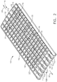
- Cascade 10, as seen in FIG. 1 is a component of a thrust reverser assembly and is mounted to nacelle 12 of a jet engine 14 of aircraft 16.
- a blocker (not shown) of the thrust reverser assembly directs exhaust air flow from jet engine to and through cascade 10.
- the configuration of cascade 10 further directs the exhaust air flow which exits cascade 10.
- Cascades 10 include surfaces which will selectively direct the exhaust air flow in a forward and side directions as needed.
- the direction of the air flow is tailored by the direction of the surfaces of vanes 18, as seen in FIG. 2 , within cascade 10 which selectively direct the exhaust air flow in a forward direction 20 of aircraft 16 and strong-back members 22, which extend in forward and aft directions 20, 24 of aircraft 16 which selectively direct the exhaust air flow in a side-turning direction.
- a method for manufacturing and assembling cascade 10 for a thrust reverser will be discussed herein, wherein the manufacturing and assembly will be streamlined so as to require less labor, cost and production time. Furthermore, the methodology for manufacturing and assembling of cascade 10 in the present disclosure will be performed without compromising the needed aerodynamic performance of cascade 10 which would otherwise lead to yet additional installation and re-certification costs.
- each strip assembly 19 is configured with no more than three sides positioned on one or both sides of strong back member 22 providing a more simplified shape than a four sided shape. This open construction of no more than three sides provides ease in installation, removal and tracking procedures of the strip assemblies 19. Additionally the assembling of strip assemblies 19 into fabricating cascade 10 will permit the fabricator the versatility to provide needed orientation of surfaces with respect to strip assemblies 19 which in turn will not compromise the needed aerodynamic performance of cascade 10.
- method 26 includes step 28 of manufacturing cascade 10 for a thrust reverser for jet engine 14 which includes forming strip assembly 19 by way of methodologies mentioned above an in this example by way of thermal compressing thermoplastic resin.
- Strip assembly 19 includes strong back member 22 having length L, as seen in FIG. 3 .
- Strip assembly 19 further includes plurality of first vane members 30 which extend from a first side 32 of the strong back member 22 in first direction 34 non-parallel relative to length L of strong back member 22 wherein first vane members 30 are spaced apart from one another along length L of strong back member 22.
- Plurality of first vane members 30 includes curvilinear surface 36, as seen in FIG. 5 .
- Curvilinear surface 36 forms recess 38 facing forward direction 20 with respect to aircraft 16, as seen in FIG. 3 , of strip assembly 19.
- Step 28 of manufacturing cascade 10 further includes top portion 42 of curvilinear surface 36 extends in second direction 44 nonparallel relative to central axis 46 of jet engine 14.
- second direction 44 forms angle A relative to central axis 46 of jet engine 14 in a range including thirty degrees up to and including ninety degrees.
- Exhaust air flow of engine 14 is selectively directed in forward direction 20 of aircraft 16 providing braking for aircraft 16 in a landing maneuver.
- Method 26 further includes plurality of second vane members 48, as seen in FIG. 3 .
- Second vane members 48 which extend from second side 50 of the strong back member 22, opposing first side 30 of strong back member 22, in third direction 52 nonparallel relative to length L of strong back member 22.
- the plurality of second vane members 48 are spaced apart from one another along length L of strong back member 22, as seen in FIG. 3 .
- one first vane member 30 of the plurality of first vane members 30 and one second vane member 48 of plurality of second vane members 48 extend in alignment with one another which contribute to providing first embodiment configuration of vane assembly 74 as seen in FIG. 2 and which will be further discussed herein.
- juncture 53 of strong back member 22, first vane member 30 and second vane member 48 is a continuous structure providing a desired strengthened interconnection of strong back member 22 with first and second vane members 30, 48.
- each of plurality of first vane members 30 is positioned to extend from the strong back member 22 in alignment with one second vane member 48 of plurality of the second vane members 48.
- This structure arrangement provides a three sided configuration positioned on either side of strong back member 22 with spaced apart first vane members 30 and first side 32 of strong back 22 on one side of strong back member 22 and second vane members 48 spaced apart on second side 50 of strong back member 22.
- This simplified open configuration for strip assembly 19 provides for less complicated molding steps, less labor efforts along with no compromise in aerodynamic surfaces so as to precipitate a need for recertification.
- first vane member 30 and second vane member 48 are seen in which first vane member 30 extends from strong back member 22 in alignment with one second vane member 48.
- a second example of a configuration of first vane member 30 and second vane member 48 is seen in FIG. 7 wherein a length L' of one of the plurality of first vane member 30 and length L" of one of the plurality of second vane member 48 are positioned in angular relationship to one another.
- This configuration will provide additional support for cascade 10 with respect to exhaust air flow of engine 14 being diverted through cascade 10 as will be discussed further herein with the assembling of cascade 10.
- This configuration will provide the ability to assemble second embodiment of the angular arrangement of vane assembly 74' which will be discussed herein.
- At least one second vane members 48 is similar in construction in this example to first vane members 30, as seen in FIG. 3 .
- At least one second vane member 48 includes curvilinear surface 54 which forms recess 56 and which faces forward direction 20 of aircraft 16.
- Top portion 58 of curvilinear surface 54 of second vane members 48 extends in second direction 44 as shown in FIG. 3 . This configuration is similar to that shown in FIGS. 3 and 5 for first vane members 30.
- Second direction 44 for second vane members 48 is nonparallel to central axis 46 of jet engine 14 (not shown) as is second direction 44 of first vane members 30 such that, with the strip assembly 19 positioned on nacelle 12 of jet engine 14, second direction 44 for second vane members 48 form an angle relative to central axis 46 of jet engine 14 in a range including thirty degrees up to and including ninety degrees, similarly as described above and as shown for first vane member 30 in FIG. 5 .
- Step 28 further includes strong back member 22 including first side surface 32 which extends along length L of strong back member 22 and extends transverse to length L of strong back member 22. Also included is second side surface 50 of strong back member 22 opposing first side 32, wherein second side surface 50 also extends along length L of strong back member 22 and extends transverse to length L of strong back member 22, as seen in FIG. 3 . As seen in FIG. 8 , first side surface 32 of the strong back member 22 has top portion 59 such that, with strip assembly 19 positioned on nacelle 12 of jet engine 14, as seen in FIG.
- top portion 59 of first side surface 32 extends in fourth direction 60 relative to radial direction 62 which extends from central axis 46 of jet engine 14 and aligned with strong back member 22 positioned closer to central axis 46 of jet engine 14 than top portion 59 of first side 32 of strong back member 22.
- Fourth direction 60 extends relative to radial direction 62 within an angular range including extending parallel with radial direction 62 and up to and including being angularly displaced sixty degrees from radial direction 62 as indicated for example by angle B.
- Second side 50 opposing first side 32 of strong back member 22 extends along length L of strong back member 22 and extends transverse to length L of strong back member 22.
- Second side 50 of strong back member 22 has top portion 64 such that, with strip assembly 19 positioned on nacelle 12 of jet engine 14, top portion 64 of second side surface 50 extends in fifth direction 66 relative to radial direction 62 which extends from central axis 46 of jet engine 14 and aligned with strong back member 22 positioned closer to central axis 46 of jet engine 14 than top portion 64 of second side 50 of strong back member 22.
- Fifth direction 66 extends relative to radial direction 62 within an angular range including extending parallel with radial direction 62 and up to and including being angularly displaced sixty degrees from radial direction 62, as seen for example as angle C in FIG. 8 .
- This variable configuration for first surface 32 and second surface 50 of strong back member 22 provides the fabricator the ability to manufacture cascade 10 to provide a selected directed side turning of exhaust air flow from jet engine 14, depending on the position of a particular cascade 10 is located on nacelle 12, so as direct exhaust air flow away from aircraft parts as needed.
- method 68 of assembling cascade 10 for a thrust reverser for jet engine 14 includes step 70 of placing strip assembly 19 into a first position, as seen in FIG. 3 , wherein strip assembly 19 includes strong back member 22 having length L, as earlier described.
- Strip assembly 19 further includes plurality of first vane members 30 which extend from first side 32 of strong back member 22 in first direction 34 nonparallel relative to length L of strong back member 22, as seen in FIG. 3 .
- First vane members 30 are spaced apart from one another along length L of strong back member 22.
- Method 68 further includes step 72 of placing second strip assembly 19' into a second position, as seen in FIG. 3 , wherein second strip assembly 19' includes second strong back member 22' including length L. It is to be noted FIG.
- Second strip assembly 19' further includes plurality of third vane members 48' which extend from second side 50' of second strong back member 22' in a third direction 52, in this example, nonparallel relative to length L of second strong back member 22.
- Plurality of third vane members 48' are spaced apart from one another along length L of second strong back member 22. With strip assembly19 in first position and second strip assembly 19' in second position, one of the plurality of first vane members 30 adjoins one of the plurality of third vane members 48' which form vane assembly 74 as seen for example in FIG. 2 .
- method 68 of assembling further includes distal end 76 of one of the plurality of first vane members 30 relative to first side 32 of the strong back member 22 and distal end 78 of one of plurality of third vane members 48'relative to second side 50' of second strong back member 22' adjoin one another in forming vane assembly 74 as seen in FIG. 3 with utilizing various configurations as will be described herein.
- a first example of the various configurations that can be employed to distal end 76 and distal end 78 includes distal end 76 of first vane member 30 extends along first plane 80, as seen in FIG. 3 and distal end 78 of third vane member 48' extends along second plane 82 wherein first plane 80 and second plane 82 extend in the same direction.
- first vane member 30 and third vane member 48' are adjoined with respect to one another into vane assembly 74.
- a second configuration is shown for example in FIG. 10 .
- Distal end 76 of first vane member 30 of one of plurality of first vane members 30 defines an angularly shaped configuration 84 and distal end 78 of third vane member 48' of one of plurality of third vane members 48' defines a complementary shape 86 relative to angularly shaped configuration 84.
- angularly shaped configuration 84 fits into complementary shape 86 with first vane member 30 and third vane member 48' adjoined with respect to one another into vane assembly 74.
- the configurations for first vane member 30 and for third vane member 48' can be exchanged such that first vane member includes complementary configuration 86 and third vane member 48' includes configuration 84.
- a third configuration is shown for example in FIG. 11 .
- Distal end 76 of first vane member 30 of one of plurality of first vane members 30 defines protrusion 88 and distal end 78 of third vane member 48' of plurality of third vane members 48' defines notch 90.
- Protrusion 88 and notch 90 are complementary in shape to one another interlocking one of plurality of first vane member 30 and one of the plurality of third vane member 48'.
- the configurations for first vane member 30 and for third vane member 48' can be exchanged such that first vane member includes notch 90 and third vane member 48' includes protrusion 88.
- Method 68 of assembling of cascade 10 further includes one of the plurality of first vane members 30, as seen in FIG. 7 extends away from first side 32 of strong back member 22 toward second strong back member 22'.
- One of plurality of third vane members 48' extends away from second side 50' of second strong back member 22' toward strong back member 22 positioning one of the plurality of the first vane members 30 and one of the plurality of third vane members 48'in angular relationship to one another.
- This adjoining configuration provides a strong resistant vane assembly 74 with this angular configuration receiving exhaust air flow moving toward aft direction 24 from jet engine 14 with the thrust reverser in operation.
- Method 68 further includes strong back member 22 including front portion 40 which extends from first side 32 of strong back member 22.
- Second strong back member 22' includes a second front portion 40' which extends from second side 50' of second strong back member 22' as seen for example in FIGS. 3 and 12 . With strip assembly 19 in the first position and second strip assembly 19' in the second position front portion 40 of strong back member 22 adjoins second front portion 40' of second strong back member 22'.
- example configurations are shown of adjoining front portion 40 and second front portion 40'.
- Cascade 10 can utilize one or more of these example configurations of adjoining front portion 40 and second front portion 40' that are shown in FIG. 12 .
- distal end 92 of front portion 40 of strong back member 22 and distal end 94 of second front portion 40' of second strong back member 22' adjoin one another in one of several configurations discussed herein.
- distal end 92 of the front portion 40 of strong back member 22 extends in a first plane 96 (generally represented by arrow 96) and distal end 94 of second front portion 40' of second strong back member 22' extends in second plane 98 (generally represented by arrow 98) wherein first plane 96 and second plane 98 extend in the same direction.
- one of distal end 92 of front portion 40 of strong back member 22 or distal end 94 of second front portion 40' of second strong back member 22' defines an angularly shaped configuration 100. In the example shown in FIG. 12 , distal end 92 has angularly shaped configuration 100.
- distal end 92 of front portion 40 of strong back member 22 or distal end 94 of second front portion 40' of second strong back member 22' defines a complementary shape 102 to the angularly shaped configuration 100.
- distal end 94 has complementary shape 102.
- distal end 92 of front portion 40 of one of front portion 40 of strong back member 22 or distal end 94 of second front portion 40' of second strong member 22' defines protrusion 104.
- distal end 92 of front portion 40 defines protrusion 104.
- the other of distal end 92 of front portion 40 of strong back member 22 or second front portion 40' of second strong back member 22' defines notch 106.
- distal end 94 of second front portion 40' defines notch 106.
- Protrusion 104 and notch 106 are complementary in shape to one another interlocking front portion 40 of strong back member 22 and second front portion 40' of second strong back member 22'.
- Vane assemblies 74 which include for example first vane member 30 and third vane member 48' in cascade 10 and front portions including front portion 40 and second front portion 40' can be secured to secured to one another in the assembling of cascade 10.
- a variety of securements can be used employing methodologies such as patch bonding, glue bonding, welding or applying rivets or other types of fasteners.
- cascade 10 can be assembled onto nacelle 12 with securement of each strip assembly at the opposing ends of the strip assemblies to nacelle 12.
- Cascade 10 as described above includes strip assembly 19, which further includes strong back member 22 having plurality of first vane members 30 which extend from first side 32 of strong back member 22 as seen in FIG. 3 .
- Cascade 10 further includes second strip assembly 19', as seen in FIG. 3 , which also includes second strong back member 22' which further includes plurality of third vane members 48' which extend from second side 50' of second strong back member 22'.
- Strip assembly 19, as seen in FIGS. 2 and 3 is secured in this example at opposing end portions 108, 110 of strip assembly 19 to nacelle 12 with rivets 112 as shown schematically in FIG. 2 .
- Second strip assembly 19' is secured at opposing end portions 108, 110 of second strip assembly 19' to nacelle 12 such that, with each of strip assembly 19 and second strip assembly 19' secured to nacelle 12, distal end 76 of one of the first vane members 30 adjoins distal end 78 of one of third vane members 48'.
- At least one of plurality of first vane members 30 and at least one of plurality of third vane members 48' include curvilinear surface 36 and 54' respectively, as seen in FIGS. 3 and 5 .
- the curvilinear surfaces form recess 38 with respect to first vane members 30 and recess 56' with respect to third vane members 48' which face in forward direction 20 with respect to aircraft 16.
- first vane member 30 which is similar to that of third vane member 48' (not shown), with strip assembly 19 positioned on nacelle 12 of jet engine 14, second direction 44 forms an angle A relative to central axis 46 of jet engine 14 in a range including thirty degrees up to and including ninety degrees.
- This angular range provides the fabricator with the versatility of directing exhaust air flow from first vane member 30 and third vane member 48' into selected needed directions.
- vane assembly 74 which includes length L' of at least one of the plurality of first vane members 30 and length L" of at least one of the plurality of third vane members 48' are positioned in angular relationship to one another forming second vane assembly 74' between strip assembly 19 and second strip assembly 19'.
- Cascade 10 includes strong back member 22, as seen in FIGS. 3 and 8 , which includes first side 32 and second side 50 opposing first side 32.
- First side 32 extends along length L of strong back member 22 and extends transverse to length L of strong back member 22 and second side 50 extends along length L of strong back member 22 and extends transverse to length L of strong back member 22.
- First side 32 of strong back member 22 has top portion 59 such that with strip assembly 19 positioned on nacelle 12 of jet engine 14, top portion 59 of first side 32 extends in fourth direction 60 relative to radial direction 62 which extends from central axis 46 of jet engine 14 and aligned with strong back member 22 positioned closer to central axis 46 of jet engine 14 than top portion 59 of first side 32 of strong back member 22.
- Fourth direction 60 is angularly positioned with respect to radial direction 62 in a directional range which includes parallel to radial direction 62 to and including up to sixty degrees angularly displaced from parallel with radial direction 62.
- second side 50 of strong back member 22 has top portion 64 such that with strip assembly 19 positioned on nacelle 12 of jet engine 14 top portion 64 of second side 50 extends in fifth direction 66 relative to radial direction 62 which extends from central axis 46 of jet engine 14 and aligned with strong back member 22 positioned closer to central axis 46 of jet engine 14 than top portion 59 of second side 50 of strong back member 22.
- Fifth direction 66 is angularly positioned with respect to radial direction 62 in a directional range which includes parallel to radial direction 62 to and including up to sixty degrees angularly displaced from parallel with radial direction 62.
- Cascade 10 further includes at least one of the plurality of the first vane members 30 include a distal end 76 relative to strong back member 22.
- Cascade 10 further includes at least one of the plurality of third vane members 48' which includes distal end 78 relative to second strong back member 22.
- Distal end 76 of first vane members 30 adjoin distal end 78 of third vane members 48'in one of the several configurations described herein.
- distal end 76 of at least one of the first vane members 30 extends along in first plane 96 and distal end 78 of one of the third vane members 48'extends along in second plane 98, wherein first plane 96 and second plane 98 extend in the same direction.
- distal end 76 of one of the plurality of first vane members 30 or distal end 78 of one of the plurality of third vane members 48' defines an angularly shaped configuration 84 and distal end 78 of the other of one of the plurality of first vane members 30 or of one of the plurality of third vane members 48' defines complementary shape 86 relative to angularly shaped configuration 84.
- distal end 76 defines angularly shaped configuration 84 and distal end 78 defines complementary shape 86.
- a third configuration example as seen in FIG.
- distal end 76 of one of the plurality of first vane members 30 or distal end 78 of one of the plurality of third vane members 48' defines protrusion 88.
- Distal end 76 of the other of one of the plurality of first vane members 30 or of the one of the plurality of the third vane members 48' defines notch 90.
- Protrusion 88 and notch 90 are complementary in shape to one another interlocking one of the plurality of the first vane members 30 and one of the plurality of the third vane members 48'.
- another method 112 for manufacturing another example of cascade 10', for a thrust reverser for a jet engine 14 includes the step of forming 114 vane strip assembly 116 which includes vane member 118 which comprises length 120 and a plurality of first strong back members 122 which extend from first side 124 of vane member 118 in first direction 123.
- First direction 123 is nonparallel relative to length 120 of vane member 118 wherein plurality of the first strong back members 122 are spaced apart from one another along length L of vane member 118.
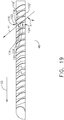
- the step of forming 114 further includes vane member 118, as seen in FIG. 3 , including curvilinear surface 128 wherein curvilinear surface 128 forms recess 130 facing forward direction 20. This configuration is also seen in FIG. 19 . Further included is top portion 126 of curvilinear surface 128 which extends in a second direction 44 nonparallel relative to central axis 46 of jet engine 14 such that, with vane strip assembly 116 positioned on nacelle 12 of jet engine 14, second direction 44 forms an angle A relative to central axis 46 of jet engine 14 in a range including thirty degrees up to and including ninety degrees providing turning jet engine 14 thrust into a direction more aligned in this example with forward direction 20.
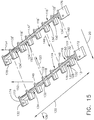
- Step 114 of forming further includes a plurality of second strong back members 132, as seen in FIG. 15 , which extend from second side 134 of vane member 118, opposing first side 124 of vane member 118, in third direction 136 nonparallel relative to length 120 of vane member 118.
- Plurality of second strong back members 132 are spaced apart from one another along length L of vane member 118.
- Step 114 of forming further includes one first strong back member 122 of the plurality of first strong back members 122 and one second strong back member 132 of the plurality of second strong back members 132 extend in alignment with one another.
- each of plurality of the first strong back members 122 is positioned to extend from vane member 118 in alignment with one second strong back member 132 of the plurality of the second strong back members 132.
- Step 114 of forming of method 112 further includes first strong back member 122 of FIG. 15 can be seen as earlier described and similarly structured strong back member 22 in FIG. 8 .
- the configuration of first strong back member 122 will be described in relationship to FIG. 8 wherein first strong back member 122 will be referred to and shown as strong back member 22, in FIG. 8 .
- Strong back 22 includes first side 32 and second side 50 opposing first side 32.
- First side 50 of the strong back member 22 has a top portion 59 such that, with the vane strip assembly 116 positioned in cascade 10', as seen in FIG. 14 and secured, for example, to nacelle 12 as shown for cascade 10 in FIG. 1 , top portion 59 of first side 32 extends in fourth direction 60 relative to radial direction 62.
- Radial direction 62 extends from central axis 46 of jet engine 14, as seen in FIG. 8 and is aligned with strong back member 22 positioned closer to central axis 46 of jet engine 14 than top portion 59 of first side 32 of strong back member 22.
- Fourth direction 60 represents a direction in which first side 32 extends for this example.
- Fourth direction 60 extends in a direction relative to radial direction 62 within an angular range including extending parallel with radial direction 62 and up to and including being angularly displaced sixty degrees from radial direction 62.
- strong back member 22 can be angularly positioned as chosen and also shown in FIG. 8 .
- Strong back member 22 has second side 50 that has top portion 64 such that, with vane strip assembly 116 as part of cascade 10', as seen in FIG. 14 , and vane strip assembly 116 further positioned on nacelle 12 of jet engine 14, as for example shown for cascade 10 in FIG.
- top portion 64 of second side 50 extends in fifth direction 66 relative to radial direction 62, in another example, which extends from central axis 46 of jet engine 14 and aligned with strong back member 22 positioned closer to central axis 46 of jet engine 14 than top portion 64 of second side 50 of strong back member 22.
- Fifth direction 66 extends relative to radial direction 62 within an angular range including extending parallel with radial direction 62 and up to and including being angularly displaced sixty degrees from radial direction 62.
- method 138 for assembling cascade 10' for a thrust reverser for a jet engine 14 includes step 140 for placing vane strip assembly 116 into a first position, as seen in FIG. 15 .
- Vane strip assembly 116 includes vane member 118 which includes length 120.
- Vane strip assembly 116 further includes plurality of first strong back members 122 which extend from first side 124 of vane member 118 in first direction 123 nonparallel relative to length 120 of vane member118.
- First strong back members 122 are spaced apart from one another along length 120 of vane member 118 as seen in FIG. 15 .
- Method 138 of FIG. 16 further includes step 142 for placing second vane strip assembly 116' into a second position, as seen in FIG. 15 , wherein second vane strip assembly 116' includes second vane member 118' which includes length 120.
- Second vane strip assembly 116' further includes plurality of third strong back members 132' which extend from second side 134' of second vane member 118' in third direction 146 nonparallel relative to length 120 of second vane member 118'.
- Plurality of third strong back members 132' are spaced apart from one another along length 120 of second vane member 118'.
- Method 138 of assembling includes a distal end 148 of one of the plurality of first strong back members 122, relative to first side 124 of vane member 118, and distal end 150 of the one of the plurality of third strong back members 132', relative to second side 134' of the second vane member 118', adjoin one another in one of the following discussed configurations.
- distal end 148 of one of the first strong back members 122 as seen in FIG.
- first plane 152 and second plane 154 extend in the same direction which includes one of a wide selection of directions.
- distal end 156 of one of plurality of strong back members 122 or distal end 158 of one of the plurality of third strong back members 132' defines an angularly shaped configuration 160.
- the angular configuration 160 is associated with distal end 156 of strong back member 122.
- Distal end of the other of the one of the plurality of first strong back members 122 or of the one of the plurality of third strong back members 132' defines a complementary shape 162 relative to the angularly shaped configuration 160.
- the complementary shape 162 is associated with distal end 158 of third strong back member 132'. This alignment of distal ends can be reversed such that angularly shaped configuration 160 could be associated with distal end 158 and the complementary shape 162 could be associated with distal end 156.
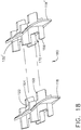
- distal end of one of the plurality of first strong back members 122 or a distal end of the one of the plurality of third strong back members 132' defines a protrusion 168 and the distal end of the other of the one of the plurality of first strong back members 122 or of the one of the plurality of the third strong back members 132' defines notch 170, wherein protrusion 168 and notch 170 are complementary in shape to one another permitting interlocking of one of the plurality of the first strong back member 122 and the one of the plurality of the third strong back member 132'.
- FIG. 18 distal end of one of the plurality of first strong back members 122 or a distal end of the one of the plurality of third strong back members 132' defines a protrusion 168 and the distal end of the other of the one of the plurality of first strong back members 122 or of the one of the plurality of the third strong back members 132' defines notch 170, wherein protrusion 168 and notch 170 are complementary in
- the protrusion 168 is associated with distal end 164 of first strong back member 122 and notch 170 is associated with distal end 166 of third strong back member 132'.
- the alignment of distal ends can be reversed such that protrusion 168 can be associated with distal end 166 and notch 170 can be associated with distal end 164.
- reverse thruster cascade 10' includes vane strip assembly 116 which includes vane member 118 including plurality of first strong back members 122 which extend from first side 124 of vane member 118.
- Second vane strip assembly 116' includes second vane member 118' including a plurality of third strong back members 132' which extend from second side 134' of second vane member 118'.
- Vane strip assembly 116 is secured at opposing end portions 172, 174 of vane strip assembly 116 to nacelle 12, as seen for cascade 10 in FIG. 1 .
- Second vane strip assembly 116' is secured at opposing end portions 176, 178 of second vane strip assembly 116' to nacelle 12, as also seen for cascade 10 in FIG. 1 .
- a distal end 148, for example as seen in FIG. 15 of one of the plurality of first strong back members 122 adjoins distal end 150 of one of the plurality of third strong back members 132'.
- vane member 118 and second vane member 118' include a curvilinear surface 128 wherein curvilinear surface 128 forms recess 130 facing forward position 20. This is seen in FIG. 15 and shown as well in FIG. 19 .
- Vane member 118 a top portion 126 of curvilinear surface 128 extends in second direction 44 nonparallel relative to central axis 46 of jet engine 14 such that, with vane strip assembly 116 positioned on nacelle 12 of jet engine 14, such as seen for example in FIG. 1 .
- Second direction 44 forms an angle A relative to central axis 46 of jet engine 14 in a range including thirty degrees up to and including ninety degrees.
- adjoining first strong back member 122 and third strong back member 132' forming a strong back assembly 180 will often have similar curvature configurations with respect to one another such as to direct engine exhaust from strong back assembly 180 in a desired direction laterally with respect to engine 14.
- First strong back member 122 includes, as earlier discussed as being similar in structure as strong back member 22 and shown in FIG. 8 , a first side 32 and second side 50 opposing first side 32.
- First side 32 of first strong back member 122 has top portion 59 such that with vane strip assembly 116 positioned on nacelle 12 of jet engine 14, top portion 59 of first side 32 extends in fourth direction 60 relative to radial direction 62.
- Radial direction 62 extends from central axis 46 of jet engine 14 aligned with first strong back member 122 positioned closer to central axis 46 of jet engine 14 than top portion 59 of first side 32 of first strong back member 122.
- Fourth direction 60 in this example, is angularly positioned with respect to radial direction 62 in an angular range which includes parallel to radial direction 62 to and including up to sixty degrees angularly displaced from parallel with radial direction 62.
- Second side 50 as seen in FIG. 8 , strong back member 22, which is similarly structured to first strong back members 122, has top portion 64 such that with vane strip assembly 116 positioned on nacelle 12 of jet engine 14, as seen for example with respect to cascade 10 in FIG. 1 , top portion 64 of second side 50 extends in fifth direction 66 relative to radial direction 62.
- Radial direction 62 extends from central axis 46 of jet engine 14 aligned with strong back member 22, as seen in FIG. 8 , positioned closer to central axis 46 of jet engine 14 than top portion 64 of second side 50 of strong back member 22 and similarly for first strong back member 122.
- Fifth direction 66 in this example, is angularly positioned with respect to radial direction 62 in an angular range which includes parallel to radial direction 62 to and including up to sixty degrees angularly displaced from parallel with radial direction 62.
- distal end 148 of one of plurality of the first strong back members 122 and distal end 150 of one of the plurality of third strong back members 132' adjoin one another in one of the following configurations discussed herein.
- distal end 148 of one of the plurality of first strong back members 122 extend along in first plane 152
- distal end 150 of the one of the plurality of third strong back members 132' extend along in a second plane 154 wherein first plane 152 and second plane 154 extend in the same direction.
- distal end 156 of one of plurality of strong back members 122 or distal end 158 of one of the plurality of third strong back members 132' defines an angularly shaped configuration 160.
- the angular configuration 160 is associated with distal end 156 of strong back member 122.
- Distal end of the other of the one of the plurality of first strong back members 122 or of the one of the plurality of third strong back members 132' defines a complementary shape 162 relative to the angularly shaped configuration 160.
- the complementary shape 162 is associated with distal end 158 of third strong back member 132'. This alignment of distal ends can be reversed such that angularly shaped configuration 160 could be associated with distal end 158 and the complementary shape 162 could be associated with distal end 156.
- distal end of one of the plurality of first strong back members 122 or a distal end of the one of the plurality of third strong back members 132' defines a protrusion 168 and the distal end of the other of the one of the plurality of first strong back members 122 or of the one of the plurality of the third strong back members 132' defines notch 170, wherein protrusion 168 and notch 170 are complementary in shape to one another permitting interlocking of one of the plurality of the first strong back member 122 and the one of the plurality of the third strong back member 132'.
- FIG. 18 distal end of one of the plurality of first strong back members 122 or a distal end of the one of the plurality of third strong back members 132' defines a protrusion 168 and the distal end of the other of the one of the plurality of first strong back members 122 or of the one of the plurality of the third strong back members 132' defines notch 170, wherein protrusion 168 and notch 170 are complementary in
- the protrusion 168 is associated with distal end 164 of first strong back member 122 and notch 170 is associated with distal end 166 of third strong back member 132'.
- the alignment of distal ends can be reversed such that protrusion 168 can be associated with distal end 166 and notch 170 can be associated with distal end 164.
- Reverse thruster cascade 10' as shown in FIGS. 14 and 15 includes vane strip assembly 116 which includes vane member 118 including a plurality of first strong back members 122 which extend from first side 124 of vane member 118.
- Cascade 10' further includes second vane strip assembly 116' including second vane member 118'including a plurality of third strong back members 132'which extend from second side 134' of second vane member 118.
- Vane strip assembly 116 is secured at opposing end portions 172, 174 of vane strip assembly 116 to nacelle 12 with a securement commonly used for securement to nacelle 12.
- Second vane strip assembly 116' is secured at opposing end portions 176, 178 of second vane strip assembly 116' to nacelle 12, also with a securement commonly used for securement to nacelle 12, such that with each of vane strip assembly 116 and second vane strip assembly 116'secured to nacelle 12 a distal end 148 of one of plurality of first strong back members 122 adjoins distal end 150 of one of the plurality of third strong back members 132'.
Landscapes
- Engineering & Computer Science (AREA)
- Chemical & Material Sciences (AREA)
- Combustion & Propulsion (AREA)
- Mechanical Engineering (AREA)
- General Engineering & Computer Science (AREA)
- Turbine Rotor Nozzle Sealing (AREA)
- Wind Motors (AREA)
Applications Claiming Priority (1)
| Application Number | Priority Date | Filing Date | Title |
|---|---|---|---|
| US15/605,120 US10823112B2 (en) | 2017-05-25 | 2017-05-25 | Method for manufacturing and assembly of a thrust reverser cascade |
Publications (2)
| Publication Number | Publication Date |
|---|---|
| EP3406887A1 true EP3406887A1 (fr) | 2018-11-28 |
| EP3406887B1 EP3406887B1 (fr) | 2021-04-07 |
Family
ID=61007497
Family Applications (1)
| Application Number | Title | Priority Date | Filing Date |
|---|---|---|---|
| EP18152219.4A Active EP3406887B1 (fr) | 2017-05-25 | 2018-01-18 | Cascade d'inverseur de poussée |
Country Status (4)
| Country | Link |
|---|---|
| US (1) | US10823112B2 (fr) |
| EP (1) | EP3406887B1 (fr) |
| CN (1) | CN108930611B (fr) |
| ES (1) | ES2876204T3 (fr) |
Cited By (5)
| Publication number | Priority date | Publication date | Assignee | Title |
|---|---|---|---|---|
| EP3623611A1 (fr) * | 2018-09-14 | 2020-03-18 | Rohr, Inc. | Réseau d'inverseur de poussée en cascade et son procédé de production |
| EP3726038A1 (fr) * | 2019-04-17 | 2020-10-21 | Hutchinson | Procédé de fabrication d'une grille pour un inverseur de poussée |
| FR3095677A1 (fr) * | 2019-05-03 | 2020-11-06 | Safran Aircraft Engines | Grille d’inverseur de poussée incluant un traitement acoustique |
| FR3146172A1 (fr) * | 2023-02-28 | 2024-08-30 | Safran Nacelles | Anneau d’inversion de poussee pour inverseur de poussee de nacelle d’aeronef et nacelle d’aeronef |
| FR3146173A1 (fr) * | 2023-02-28 | 2024-08-30 | Safran Nacelles | Module d’inversion de poussee d’un anneau d’inversion de poussee pour inverseur de poussee de nacelle d’aeronef |
Families Citing this family (13)
| Publication number | Priority date | Publication date | Assignee | Title |
|---|---|---|---|---|
| US10598127B2 (en) * | 2017-08-15 | 2020-03-24 | Spirit Aerosystems, Inc. | Method of fabricating a thrust reverser cascade assembly |
| US11073032B2 (en) * | 2018-07-25 | 2021-07-27 | Rohr, Inc. | Cascade array vanes with assembly features |
| US10865736B2 (en) * | 2017-10-18 | 2020-12-15 | Spirit Aerosystems, Inc. | Cascade segment for thrust reverser with repeating modular units, and method of manufacturing same |
| US11674474B2 (en) * | 2018-06-19 | 2023-06-13 | Short Brothers Plc | Thrust reverser cascade and method of manufacture |
| US11078871B2 (en) * | 2018-12-21 | 2021-08-03 | Rohr, Inc. | Thrust reverser system with cascades |
| US11123916B2 (en) | 2019-05-06 | 2021-09-21 | Rohr, Inc. | Forming a thrust reverser cascade using corrugated bodies |
| FR3098256B1 (fr) | 2019-07-04 | 2021-10-29 | Dedienne Multiplasturgy Group | Grille composite d’inverseur de poussée à jonctions renforcées de fibres longues |
| AT523287B1 (de) * | 2020-07-13 | 2021-07-15 | Facc Ag | Kaskadenelement für ein Schubumkehrsystem eines Triebwerks |
| US12196156B2 (en) * | 2021-07-30 | 2025-01-14 | The Boeing Company | Symmetric cascade thrust reversers and related methods |
| FR3144636B1 (fr) * | 2022-12-29 | 2025-01-03 | Safran Nacelles | Grille d’inverseur de poussee d’un reacteur d’aeronef |
| FR3148222A1 (fr) | 2023-04-26 | 2024-11-01 | Airbus Operations (S.A.S.) | Nacelle d’aéronef équipée d’au moins un dispositif d’inversion de poussée comprenant au moins un déflecteur longitudinal, aéronef comprenant au moins un ensemble de propulsion comportant une telle nacelle |
| EP4528093A1 (fr) * | 2023-09-20 | 2025-03-26 | Airbus Operations (S.A.S.) | Nacelle d'aéronef équipée d'au moins un dispositif d'inversion de poussée comprenant au moins un déflecteur longitudinal, aéronef comprenant au moins un ensemble de propulsion comportant une telle nacelle |
| CN119880443B (zh) * | 2023-10-24 | 2026-03-27 | 中国航发商用航空发动机有限责任公司 | 可调试验反推叶栅 |
Citations (6)
| Publication number | Priority date | Publication date | Assignee | Title |
|---|---|---|---|---|
| US3024604A (en) * | 1958-03-31 | 1962-03-13 | Rolls Royce | Aircraft jet propulsion apparatus with thrust reversing means |
| US3076309A (en) * | 1958-04-03 | 1963-02-05 | Rolls Royce | Aircraft jet propulsion apparatus with thrust reversing means |
| US4852805A (en) * | 1983-12-30 | 1989-08-01 | The Boeing Company | Hybrid thrust reverser cascade basket and method |
| EP2944452A2 (fr) * | 2014-05-15 | 2015-11-18 | The Boeing Company | Cascades thermoformées pour des inverseurs de poussée de turboréacteurs |
| US20160263820A1 (en) * | 2015-03-13 | 2016-09-15 | Rohr, Inc. | Method of manufacturing thrust reverser cascades |
| US9587582B1 (en) * | 2013-06-19 | 2017-03-07 | Spirit Aerosystems, Inc. | Method of fabricating a bonded cascade assembly for an aircraft thrust reverser |
Family Cites Families (40)
| Publication number | Priority date | Publication date | Assignee | Title |
|---|---|---|---|---|
| US2345200A (en) | 1940-08-03 | 1944-03-28 | Us Rubber Co | Method of manufacture of inner tubes |
| US3795559A (en) | 1971-10-01 | 1974-03-05 | Boeing Co | Aircraft fluted core radome and method for making the same |
| US3794246A (en) * | 1973-04-11 | 1974-02-26 | Aeronca Inc | Thrust reversing cascade assembly |
| US4165609A (en) | 1977-03-02 | 1979-08-28 | The Boeing Company | Gas turbine mixer apparatus |
| US4183478A (en) | 1977-11-25 | 1980-01-15 | The Boeing Company | Jet thrust reverser |
| US4778110A (en) | 1982-09-30 | 1988-10-18 | Rohr Industries, Inc. | Modular composite cascade assembly |
| US4722821A (en) | 1983-12-30 | 1988-02-02 | The Boeing Company | Method of making a cascade basket for a thrust reverser |
| US5152860A (en) | 1984-10-09 | 1992-10-06 | Anadite, Inc. | Modular composite structure and method |
| FR2616409B1 (fr) | 1987-06-09 | 1989-09-15 | Aerospatiale | Pale en materiaux composites et son procede de fabrication |
| US5128192A (en) | 1990-02-02 | 1992-07-07 | Northrop Corporation | Braided preform process for thermoplastic honeycomb cores |
| EP0590032B1 (fr) | 1991-05-24 | 1999-04-28 | Dow-United Technologies Composite Products, Inc. | Pieces tressees composites et complexes, ainsi que procede de fabrication |
| US5348601A (en) | 1993-06-23 | 1994-09-20 | The United States Of America As Represented By The Secretary Of The Navy | Method of making an offset corrugated sandwich construction |
| US6558608B2 (en) | 1995-06-28 | 2003-05-06 | Tpi Technology, Inc. | Method for molding fiber reinforced composite container |
| US5789060A (en) | 1996-07-29 | 1998-08-04 | Specialty Cellular Products Company | Heat conduction honeycomb core |
| US20010001409A1 (en) | 1999-06-08 | 2001-05-24 | Terry Weight | Method and apparatus for forming composite honeycomb core |
| US6725541B1 (en) * | 2000-01-21 | 2004-04-27 | Rolls-Royce Plc | Flow directing element and a method of manufacturing a flow directing element |
| GB0001279D0 (en) | 2000-01-21 | 2000-03-08 | Rolls Royce Plc | A flow directing element and a method of manufacturing a flow directing element |
| FR2804474B1 (fr) * | 2000-01-27 | 2002-06-28 | Hispano Suiza Sa | Inverseur de poussee a grilles aubagees de deviation a structure arriere fixe |
| FR2818578B1 (fr) | 2000-12-26 | 2003-03-21 | Snecma Moteurs | Procede de fabrication de structures en nid d'abeilles et outillage pour une telle fabrication |
| US6568172B2 (en) * | 2001-09-27 | 2003-05-27 | The Nordam Group, Inc. | Converging nozzle thrust reverser |
| FR2830051B1 (fr) | 2001-09-27 | 2003-11-07 | Hurel Hispano Le Havre | Systeme de verrouillage sur un inverseur de poussee a grilles |
| FR2849113B1 (fr) * | 2002-12-24 | 2005-02-04 | Hurel Hispano | Inverseur de poussee a grilles de deflection optimisees |
| US9102103B2 (en) | 2006-02-02 | 2015-08-11 | The Boeing Company | Thermoplastic composite parts having integrated metal fittings and method of making the same |
| US8333858B2 (en) | 2006-02-02 | 2012-12-18 | The Boeing Company | Method for fabricating curved thermoplastic composite parts |
| US9314941B2 (en) | 2007-07-13 | 2016-04-19 | Advanced Ceramics Manufacturing, Llc | Aggregate-based mandrels for composite part production and composite part production methods |
| US7998299B2 (en) | 2008-10-01 | 2011-08-16 | The Boeing Company | Method for making composite truss panel having a fluted core |
| US8583271B2 (en) | 2009-03-16 | 2013-11-12 | The Boeing Company | Controlling cutting of continuously fabricated composite parts with nondestructive evaluation |
| EP2278147B1 (fr) * | 2009-06-16 | 2014-06-25 | Rohr, Inc. | Modulation de buse de ventilation à fente variable fournissant une sortie de dérivation d'écoulement en amont |
| US9713913B2 (en) | 2010-02-04 | 2017-07-25 | Textron Innovations Inc. | Composite core and method of making same |
| US8484944B2 (en) | 2010-08-13 | 2013-07-16 | Spirit Aerosystems, Inc. | Aerodynamic device for thrust reverser cascades |
| US9073240B2 (en) | 2010-11-11 | 2015-07-07 | Spirit Aerosystems, Inc. | Reconfigurable shape memory polymer tooling supports |
| US8642151B2 (en) | 2011-01-21 | 2014-02-04 | Albany Engineered Composites, Inc. | Preform and method for reinforcing woven fiber nodes |
| EP2518593B1 (fr) | 2011-04-29 | 2013-05-29 | Research In Motion Limited | Clavier doté d'une forme incurvée |
| FR2978990A1 (fr) * | 2011-08-08 | 2013-02-15 | Aircelle Sa | Dispositif d'inversion de poussee |
| US9086034B2 (en) | 2011-10-13 | 2015-07-21 | Rohr, Inc. | Thrust reverser cascade assembly with flow deflection shelf |
| US9120246B2 (en) | 2013-03-01 | 2015-09-01 | Bell Helicopter Textron Inc. | Pressure tunable expandable mandrel for manufacturing a composite structure |
| US9145277B2 (en) | 2013-03-01 | 2015-09-29 | Bell Helicopter Textron Inc. | System and method of manufacturing composite core |
| US9211618B2 (en) | 2013-12-20 | 2015-12-15 | Bell Helicopter Textron Inc. | Method of securing composite core during a manufacturing process |
| FR3023325B1 (fr) * | 2014-07-04 | 2016-07-15 | Aircelle Sa | Cadre arriere pour une structure d'inverseur de poussee a grilles de deviation |
| FR3031727B1 (fr) * | 2015-01-21 | 2019-07-12 | Safran Nacelles | Dispositif d’inversion de poussee a grilles mobiles et berceau pour nacelle pour mat du type corps |
-
2017
- 2017-05-25 US US15/605,120 patent/US10823112B2/en active Active
-
2018
- 2018-01-18 ES ES18152219T patent/ES2876204T3/es active Active
- 2018-01-18 EP EP18152219.4A patent/EP3406887B1/fr active Active
- 2018-02-26 CN CN201810162827.0A patent/CN108930611B/zh active Active
Patent Citations (6)
| Publication number | Priority date | Publication date | Assignee | Title |
|---|---|---|---|---|
| US3024604A (en) * | 1958-03-31 | 1962-03-13 | Rolls Royce | Aircraft jet propulsion apparatus with thrust reversing means |
| US3076309A (en) * | 1958-04-03 | 1963-02-05 | Rolls Royce | Aircraft jet propulsion apparatus with thrust reversing means |
| US4852805A (en) * | 1983-12-30 | 1989-08-01 | The Boeing Company | Hybrid thrust reverser cascade basket and method |
| US9587582B1 (en) * | 2013-06-19 | 2017-03-07 | Spirit Aerosystems, Inc. | Method of fabricating a bonded cascade assembly for an aircraft thrust reverser |
| EP2944452A2 (fr) * | 2014-05-15 | 2015-11-18 | The Boeing Company | Cascades thermoformées pour des inverseurs de poussée de turboréacteurs |
| US20160263820A1 (en) * | 2015-03-13 | 2016-09-15 | Rohr, Inc. | Method of manufacturing thrust reverser cascades |
Cited By (15)
| Publication number | Priority date | Publication date | Assignee | Title |
|---|---|---|---|---|
| EP3623611A1 (fr) * | 2018-09-14 | 2020-03-18 | Rohr, Inc. | Réseau d'inverseur de poussée en cascade et son procédé de production |
| EP3726038A1 (fr) * | 2019-04-17 | 2020-10-21 | Hutchinson | Procédé de fabrication d'une grille pour un inverseur de poussée |
| WO2020212561A1 (fr) * | 2019-04-17 | 2020-10-22 | Hutchinson | Procédé de fabrication d'une grille pour un inverseur de poussée |
| FR3095158A1 (fr) * | 2019-04-17 | 2020-10-23 | Hutchinson | Procédé de fabrication d’une grille pour un inverseur de poussée |
| US12162227B2 (en) | 2019-04-17 | 2024-12-10 | Hutchinson | Method for manufacturing a grille for a thrust reverser |
| US11787127B2 (en) | 2019-04-17 | 2023-10-17 | Hutchinson | Method of manufacturing a grille for a thrust reverser |
| CN113811681A (zh) * | 2019-05-03 | 2021-12-17 | 赛峰航空器发动机 | 包括声学处理的反推装置叶栅 |
| CN113811681B (zh) * | 2019-05-03 | 2023-03-24 | 赛峰航空器发动机 | 包括声学处理的反推装置叶栅 |
| WO2020224886A1 (fr) * | 2019-05-03 | 2020-11-12 | Safran Aircraft Engines | Grille d'inverseur de poussee incluant un traitement acoustique |
| FR3095677A1 (fr) * | 2019-05-03 | 2020-11-06 | Safran Aircraft Engines | Grille d’inverseur de poussée incluant un traitement acoustique |
| US12320316B2 (en) | 2019-05-03 | 2025-06-03 | Safran Aircraft Engines | Thrust reverser cascade including acoustic treatment |
| FR3146172A1 (fr) * | 2023-02-28 | 2024-08-30 | Safran Nacelles | Anneau d’inversion de poussee pour inverseur de poussee de nacelle d’aeronef et nacelle d’aeronef |
| FR3146173A1 (fr) * | 2023-02-28 | 2024-08-30 | Safran Nacelles | Module d’inversion de poussee d’un anneau d’inversion de poussee pour inverseur de poussee de nacelle d’aeronef |
| WO2024180302A1 (fr) * | 2023-02-28 | 2024-09-06 | Safran Nacelles | Anneau d'inversion de poussee pour inverseur de poussee de nacelle d'aeronef et nacelle d'aeronef |
| WO2024180303A1 (fr) * | 2023-02-28 | 2024-09-06 | Safran Nacelles | Module d'inversion de poussee d'un anneau d'inversion de poussee pour inverseur de poussee de nacelle d'aeronef |
Also Published As
| Publication number | Publication date |
|---|---|
| ES2876204T3 (es) | 2021-11-12 |
| EP3406887B1 (fr) | 2021-04-07 |
| US20180340492A1 (en) | 2018-11-29 |
| CN108930611B (zh) | 2022-08-02 |
| US10823112B2 (en) | 2020-11-03 |
| CN108930611A (zh) | 2018-12-04 |
Similar Documents
| Publication | Publication Date | Title |
|---|---|---|
| EP3406887B1 (fr) | Cascade d'inverseur de poussée | |
| US9835112B2 (en) | Thrust reverser cascade | |
| US10683087B2 (en) | Shrouded rotary assembly from segmented composite for aircraft | |
| EP0894715B1 (fr) | Panneau extérieur d'un capot de nacelle d'un moteur avec des carénages d'un rail de guidage integrés et procédé pour sa fabrication | |
| EP2930317B1 (fr) | Entrée d'une turbine à gaz | |
| US8127530B2 (en) | Thrust reverser for a turbofan gas turbine engine | |
| EP3527812B1 (fr) | Cascade d'inverseur de poussée | |
| EP3584434B1 (fr) | Cascade d'inverseur de poussée et son procédé de fabrication | |
| EP3974641B1 (fr) | Réseau d'inverseur de poussée en cascade et son procédé de production | |
| CN110654527A (zh) | 用于推力反向器的吸声板 | |
| US20240110535A1 (en) | Thrust reverser cascade and method of manufacture | |
| EP3599370B1 (fr) | Cascade raccordée à faible coût | |
| US7478780B2 (en) | Methods for manufacturing composite aircraft, parts and a family of composite aircraft | |
| EP3599369B1 (fr) | Réseau d'aubes en cascade avec des caractéristiques d'assemblage | |
| EP3578790B1 (fr) | Ensemble en cascade pour un inverseur de poussée de turboréacteur | |
| US20200392923A1 (en) | Thrust reverser cascade and method of manufacture | |
| EP4365077A1 (fr) | Profil aérodynamique et ses procédés d'assemblage | |
| CN114671005B (zh) | 一种飞行器头锥结构及其制备方法 |
Legal Events
| Date | Code | Title | Description |
|---|---|---|---|
| PUAI | Public reference made under article 153(3) epc to a published international application that has entered the european phase |
Free format text: ORIGINAL CODE: 0009012 |
|
| STAA | Information on the status of an ep patent application or granted ep patent |
Free format text: STATUS: REQUEST FOR EXAMINATION WAS MADE |
|
| 17P | Request for examination filed |
Effective date: 20180118 |
|
| AK | Designated contracting states |
Kind code of ref document: A1 Designated state(s): AL AT BE BG CH CY CZ DE DK EE ES FI FR GB GR HR HU IE IS IT LI LT LU LV MC MK MT NL NO PL PT RO RS SE SI SK SM TR |
|
| AX | Request for extension of the european patent |
Extension state: BA ME |
|
| GRAP | Despatch of communication of intention to grant a patent |
Free format text: ORIGINAL CODE: EPIDOSNIGR1 |
|
| STAA | Information on the status of an ep patent application or granted ep patent |
Free format text: STATUS: GRANT OF PATENT IS INTENDED |
|
| RIC1 | Information provided on ipc code assigned before grant |
Ipc: F02K 1/72 20060101ALI20200923BHEP Ipc: F02K 1/64 20060101AFI20200923BHEP |
|
| INTG | Intention to grant announced |
Effective date: 20201019 |
|
| GRAS | Grant fee paid |
Free format text: ORIGINAL CODE: EPIDOSNIGR3 |
|
| GRAA | (expected) grant |
Free format text: ORIGINAL CODE: 0009210 |
|
| STAA | Information on the status of an ep patent application or granted ep patent |
Free format text: STATUS: THE PATENT HAS BEEN GRANTED |
|
| AK | Designated contracting states |
Kind code of ref document: B1 Designated state(s): AL AT BE BG CH CY CZ DE DK EE ES FI FR GB GR HR HU IE IS IT LI LT LU LV MC MK MT NL NO PL PT RO RS SE SI SK SM TR |
|
| REG | Reference to a national code |
Ref country code: GB Ref legal event code: FG4D |
|
| REG | Reference to a national code |
Ref country code: AT Ref legal event code: REF Ref document number: 1379983 Country of ref document: AT Kind code of ref document: T Effective date: 20210415 Ref country code: CH Ref legal event code: EP |
|
| REG | Reference to a national code |
Ref country code: DE Ref legal event code: R096 Ref document number: 602018014947 Country of ref document: DE |
|
| REG | Reference to a national code |
Ref country code: IE Ref legal event code: FG4D |
|
| REG | Reference to a national code |
Ref country code: LT Ref legal event code: MG9D |
|
| REG | Reference to a national code |
Ref country code: NL Ref legal event code: MP Effective date: 20210407 Ref country code: AT Ref legal event code: MK05 Ref document number: 1379983 Country of ref document: AT Kind code of ref document: T Effective date: 20210407 |
|
| PG25 | Lapsed in a contracting state [announced via postgrant information from national office to epo] |
Ref country code: LT Free format text: LAPSE BECAUSE OF FAILURE TO SUBMIT A TRANSLATION OF THE DESCRIPTION OR TO PAY THE FEE WITHIN THE PRESCRIBED TIME-LIMIT Effective date: 20210407 Ref country code: FI Free format text: LAPSE BECAUSE OF FAILURE TO SUBMIT A TRANSLATION OF THE DESCRIPTION OR TO PAY THE FEE WITHIN THE PRESCRIBED TIME-LIMIT Effective date: 20210407 Ref country code: NL Free format text: LAPSE BECAUSE OF FAILURE TO SUBMIT A TRANSLATION OF THE DESCRIPTION OR TO PAY THE FEE WITHIN THE PRESCRIBED TIME-LIMIT Effective date: 20210407 Ref country code: HR Free format text: LAPSE BECAUSE OF FAILURE TO SUBMIT A TRANSLATION OF THE DESCRIPTION OR TO PAY THE FEE WITHIN THE PRESCRIBED TIME-LIMIT Effective date: 20210407 Ref country code: BG Free format text: LAPSE BECAUSE OF FAILURE TO SUBMIT A TRANSLATION OF THE DESCRIPTION OR TO PAY THE FEE WITHIN THE PRESCRIBED TIME-LIMIT Effective date: 20210707 Ref country code: AT Free format text: LAPSE BECAUSE OF FAILURE TO SUBMIT A TRANSLATION OF THE DESCRIPTION OR TO PAY THE FEE WITHIN THE PRESCRIBED TIME-LIMIT Effective date: 20210407 |
|
| REG | Reference to a national code |
Ref country code: ES Ref legal event code: FG2A Ref document number: 2876204 Country of ref document: ES Kind code of ref document: T3 Effective date: 20211112 |
|
| PG25 | Lapsed in a contracting state [announced via postgrant information from national office to epo] |
Ref country code: IS Free format text: LAPSE BECAUSE OF FAILURE TO SUBMIT A TRANSLATION OF THE DESCRIPTION OR TO PAY THE FEE WITHIN THE PRESCRIBED TIME-LIMIT Effective date: 20210807 Ref country code: GR Free format text: LAPSE BECAUSE OF FAILURE TO SUBMIT A TRANSLATION OF THE DESCRIPTION OR TO PAY THE FEE WITHIN THE PRESCRIBED TIME-LIMIT Effective date: 20210708 Ref country code: PT Free format text: LAPSE BECAUSE OF FAILURE TO SUBMIT A TRANSLATION OF THE DESCRIPTION OR TO PAY THE FEE WITHIN THE PRESCRIBED TIME-LIMIT Effective date: 20210809 Ref country code: PL Free format text: LAPSE BECAUSE OF FAILURE TO SUBMIT A TRANSLATION OF THE DESCRIPTION OR TO PAY THE FEE WITHIN THE PRESCRIBED TIME-LIMIT Effective date: 20210407 Ref country code: LV Free format text: LAPSE BECAUSE OF FAILURE TO SUBMIT A TRANSLATION OF THE DESCRIPTION OR TO PAY THE FEE WITHIN THE PRESCRIBED TIME-LIMIT Effective date: 20210407 Ref country code: NO Free format text: LAPSE BECAUSE OF FAILURE TO SUBMIT A TRANSLATION OF THE DESCRIPTION OR TO PAY THE FEE WITHIN THE PRESCRIBED TIME-LIMIT Effective date: 20210707 Ref country code: SE Free format text: LAPSE BECAUSE OF FAILURE TO SUBMIT A TRANSLATION OF THE DESCRIPTION OR TO PAY THE FEE WITHIN THE PRESCRIBED TIME-LIMIT Effective date: 20210407 Ref country code: RS Free format text: LAPSE BECAUSE OF FAILURE TO SUBMIT A TRANSLATION OF THE DESCRIPTION OR TO PAY THE FEE WITHIN THE PRESCRIBED TIME-LIMIT Effective date: 20210407 |
|
| REG | Reference to a national code |
Ref country code: DE Ref legal event code: R097 Ref document number: 602018014947 Country of ref document: DE |
|
| PG25 | Lapsed in a contracting state [announced via postgrant information from national office to epo] |
Ref country code: DK Free format text: LAPSE BECAUSE OF FAILURE TO SUBMIT A TRANSLATION OF THE DESCRIPTION OR TO PAY THE FEE WITHIN THE PRESCRIBED TIME-LIMIT Effective date: 20210407 Ref country code: CZ Free format text: LAPSE BECAUSE OF FAILURE TO SUBMIT A TRANSLATION OF THE DESCRIPTION OR TO PAY THE FEE WITHIN THE PRESCRIBED TIME-LIMIT Effective date: 20210407 Ref country code: RO Free format text: LAPSE BECAUSE OF FAILURE TO SUBMIT A TRANSLATION OF THE DESCRIPTION OR TO PAY THE FEE WITHIN THE PRESCRIBED TIME-LIMIT Effective date: 20210407 Ref country code: SK Free format text: LAPSE BECAUSE OF FAILURE TO SUBMIT A TRANSLATION OF THE DESCRIPTION OR TO PAY THE FEE WITHIN THE PRESCRIBED TIME-LIMIT Effective date: 20210407 Ref country code: SM Free format text: LAPSE BECAUSE OF FAILURE TO SUBMIT A TRANSLATION OF THE DESCRIPTION OR TO PAY THE FEE WITHIN THE PRESCRIBED TIME-LIMIT Effective date: 20210407 Ref country code: EE Free format text: LAPSE BECAUSE OF FAILURE TO SUBMIT A TRANSLATION OF THE DESCRIPTION OR TO PAY THE FEE WITHIN THE PRESCRIBED TIME-LIMIT Effective date: 20210407 |
|
| PLBE | No opposition filed within time limit |
Free format text: ORIGINAL CODE: 0009261 |
|
| STAA | Information on the status of an ep patent application or granted ep patent |
Free format text: STATUS: NO OPPOSITION FILED WITHIN TIME LIMIT |
|
| 26N | No opposition filed |
Effective date: 20220110 |
|
| PG25 | Lapsed in a contracting state [announced via postgrant information from national office to epo] |
Ref country code: IS Free format text: LAPSE BECAUSE OF FAILURE TO SUBMIT A TRANSLATION OF THE DESCRIPTION OR TO PAY THE FEE WITHIN THE PRESCRIBED TIME-LIMIT Effective date: 20210807 Ref country code: AL Free format text: LAPSE BECAUSE OF FAILURE TO SUBMIT A TRANSLATION OF THE DESCRIPTION OR TO PAY THE FEE WITHIN THE PRESCRIBED TIME-LIMIT Effective date: 20210407 |
|
| PG25 | Lapsed in a contracting state [announced via postgrant information from national office to epo] |
Ref country code: MC Free format text: LAPSE BECAUSE OF FAILURE TO SUBMIT A TRANSLATION OF THE DESCRIPTION OR TO PAY THE FEE WITHIN THE PRESCRIBED TIME-LIMIT Effective date: 20210407 |
|
| REG | Reference to a national code |
Ref country code: CH Ref legal event code: PL |
|
| REG | Reference to a national code |
Ref country code: BE Ref legal event code: MM Effective date: 20220131 |
|
| PG25 | Lapsed in a contracting state [announced via postgrant information from national office to epo] |
Ref country code: LU Free format text: LAPSE BECAUSE OF NON-PAYMENT OF DUE FEES Effective date: 20220118 |
|
| PG25 | Lapsed in a contracting state [announced via postgrant information from national office to epo] |
Ref country code: BE Free format text: LAPSE BECAUSE OF NON-PAYMENT OF DUE FEES Effective date: 20220131 |
|
| PG25 | Lapsed in a contracting state [announced via postgrant information from national office to epo] |
Ref country code: LI Free format text: LAPSE BECAUSE OF NON-PAYMENT OF DUE FEES Effective date: 20220131 Ref country code: CH Free format text: LAPSE BECAUSE OF NON-PAYMENT OF DUE FEES Effective date: 20220131 |
|
| PG25 | Lapsed in a contracting state [announced via postgrant information from national office to epo] |
Ref country code: IE Free format text: LAPSE BECAUSE OF NON-PAYMENT OF DUE FEES Effective date: 20220118 |
|
| P01 | Opt-out of the competence of the unified patent court (upc) registered |
Effective date: 20230516 |
|
| PG25 | Lapsed in a contracting state [announced via postgrant information from national office to epo] |
Ref country code: HU Free format text: LAPSE BECAUSE OF FAILURE TO SUBMIT A TRANSLATION OF THE DESCRIPTION OR TO PAY THE FEE WITHIN THE PRESCRIBED TIME-LIMIT; INVALID AB INITIO Effective date: 20180118 |
|
| PG25 | Lapsed in a contracting state [announced via postgrant information from national office to epo] |
Ref country code: MK Free format text: LAPSE BECAUSE OF FAILURE TO SUBMIT A TRANSLATION OF THE DESCRIPTION OR TO PAY THE FEE WITHIN THE PRESCRIBED TIME-LIMIT Effective date: 20210407 Ref country code: CY Free format text: LAPSE BECAUSE OF FAILURE TO SUBMIT A TRANSLATION OF THE DESCRIPTION OR TO PAY THE FEE WITHIN THE PRESCRIBED TIME-LIMIT Effective date: 20210407 |
|
| PG25 | Lapsed in a contracting state [announced via postgrant information from national office to epo] |
Ref country code: TR Free format text: LAPSE BECAUSE OF FAILURE TO SUBMIT A TRANSLATION OF THE DESCRIPTION OR TO PAY THE FEE WITHIN THE PRESCRIBED TIME-LIMIT Effective date: 20210407 |
|
| PG25 | Lapsed in a contracting state [announced via postgrant information from national office to epo] |
Ref country code: MT Free format text: LAPSE BECAUSE OF FAILURE TO SUBMIT A TRANSLATION OF THE DESCRIPTION OR TO PAY THE FEE WITHIN THE PRESCRIBED TIME-LIMIT Effective date: 20210407 |
|
| PGFP | Annual fee paid to national office [announced via postgrant information from national office to epo] |
Ref country code: GB Payment date: 20260127 Year of fee payment: 9 |
|
| PGFP | Annual fee paid to national office [announced via postgrant information from national office to epo] |
Ref country code: ES Payment date: 20260202 Year of fee payment: 9 |
|
| PGFP | Annual fee paid to national office [announced via postgrant information from national office to epo] |
Ref country code: DE Payment date: 20260128 Year of fee payment: 9 |
|
| PGFP | Annual fee paid to national office [announced via postgrant information from national office to epo] |
Ref country code: IT Payment date: 20260121 Year of fee payment: 9 |
|
| PGFP | Annual fee paid to national office [announced via postgrant information from national office to epo] |
Ref country code: FR Payment date: 20260126 Year of fee payment: 9 |