EP3406898A1 - Composant de nacelle pour une éolienne et procédé de montage d'un composant de nacelle - Google Patents
Composant de nacelle pour une éolienne et procédé de montage d'un composant de nacelle Download PDFInfo
- Publication number
- EP3406898A1 EP3406898A1 EP18172806.4A EP18172806A EP3406898A1 EP 3406898 A1 EP3406898 A1 EP 3406898A1 EP 18172806 A EP18172806 A EP 18172806A EP 3406898 A1 EP3406898 A1 EP 3406898A1
- Authority
- EP
- European Patent Office
- Prior art keywords
- module
- electric module
- nacelle
- component
- generator
- Prior art date
- Legal status (The legal status is an assumption and is not a legal conclusion. Google has not performed a legal analysis and makes no representation as to the accuracy of the status listed.)
- Granted
Links
Images


Classifications
-
- F—MECHANICAL ENGINEERING; LIGHTING; HEATING; WEAPONS; BLASTING
- F03—MACHINES OR ENGINES FOR LIQUIDS; WIND, SPRING, OR WEIGHT MOTORS; PRODUCING MECHANICAL POWER OR A REACTIVE PROPULSIVE THRUST, NOT OTHERWISE PROVIDED FOR
- F03D—WIND MOTORS
- F03D9/00—Adaptations of wind motors for special use; Combinations of wind motors with apparatus driven thereby; Wind motors specially adapted for installation in particular locations
- F03D9/20—Wind motors characterised by the driven apparatus
- F03D9/25—Wind motors characterised by the driven apparatus the apparatus being an electrical generator
-
- F—MECHANICAL ENGINEERING; LIGHTING; HEATING; WEAPONS; BLASTING
- F03—MACHINES OR ENGINES FOR LIQUIDS; WIND, SPRING, OR WEIGHT MOTORS; PRODUCING MECHANICAL POWER OR A REACTIVE PROPULSIVE THRUST, NOT OTHERWISE PROVIDED FOR
- F03D—WIND MOTORS
- F03D13/00—Assembly, mounting or commissioning of wind motors; Arrangements specially adapted for transporting wind motor components
- F03D13/10—Assembly of wind motors; Arrangements for erecting wind motors
-
- F—MECHANICAL ENGINEERING; LIGHTING; HEATING; WEAPONS; BLASTING
- F03—MACHINES OR ENGINES FOR LIQUIDS; WIND, SPRING, OR WEIGHT MOTORS; PRODUCING MECHANICAL POWER OR A REACTIVE PROPULSIVE THRUST, NOT OTHERWISE PROVIDED FOR
- F03D—WIND MOTORS
- F03D13/00—Assembly, mounting or commissioning of wind motors; Arrangements specially adapted for transporting wind motor components
- F03D13/20—Arrangements for mounting or supporting wind motors; Masts or towers for wind motors
-
- F—MECHANICAL ENGINEERING; LIGHTING; HEATING; WEAPONS; BLASTING
- F03—MACHINES OR ENGINES FOR LIQUIDS; WIND, SPRING, OR WEIGHT MOTORS; PRODUCING MECHANICAL POWER OR A REACTIVE PROPULSIVE THRUST, NOT OTHERWISE PROVIDED FOR
- F03D—WIND MOTORS
- F03D80/00—Details, components or accessories not provided for in groups F03D1/00 - F03D17/00
- F03D80/50—Maintenance or repair
-
- F—MECHANICAL ENGINEERING; LIGHTING; HEATING; WEAPONS; BLASTING
- F03—MACHINES OR ENGINES FOR LIQUIDS; WIND, SPRING, OR WEIGHT MOTORS; PRODUCING MECHANICAL POWER OR A REACTIVE PROPULSIVE THRUST, NOT OTHERWISE PROVIDED FOR
- F03D—WIND MOTORS
- F03D80/00—Details, components or accessories not provided for in groups F03D1/00 - F03D17/00
- F03D80/80—Arrangement of components within nacelles or towers
- F03D80/82—Arrangement of components within nacelles or towers of electrical components
- F03D80/85—Cabling
-
- F—MECHANICAL ENGINEERING; LIGHTING; HEATING; WEAPONS; BLASTING
- F05—INDEXING SCHEMES RELATING TO ENGINES OR PUMPS IN VARIOUS SUBCLASSES OF CLASSES F01-F04
- F05B—INDEXING SCHEME RELATING TO WIND, SPRING, WEIGHT, INERTIA OR LIKE MOTORS, TO MACHINES OR ENGINES FOR LIQUIDS COVERED BY SUBCLASSES F03B, F03D AND F03G
- F05B2240/00—Components
- F05B2240/10—Stators
- F05B2240/14—Casings, housings, nacelles, gondels or the like, protecting or supporting assemblies there within
-
- F—MECHANICAL ENGINEERING; LIGHTING; HEATING; WEAPONS; BLASTING
- F05—INDEXING SCHEMES RELATING TO ENGINES OR PUMPS IN VARIOUS SUBCLASSES OF CLASSES F01-F04
- F05B—INDEXING SCHEME RELATING TO WIND, SPRING, WEIGHT, INERTIA OR LIKE MOTORS, TO MACHINES OR ENGINES FOR LIQUIDS COVERED BY SUBCLASSES F03B, F03D AND F03G
- F05B2240/00—Components
- F05B2240/90—Mounting on supporting structures or systems
- F05B2240/91—Mounting on supporting structures or systems on a stationary structure
- F05B2240/916—Mounting on supporting structures or systems on a stationary structure with provision for hoisting onto the structure
-
- Y—GENERAL TAGGING OF NEW TECHNOLOGICAL DEVELOPMENTS; GENERAL TAGGING OF CROSS-SECTIONAL TECHNOLOGIES SPANNING OVER SEVERAL SECTIONS OF THE IPC; TECHNICAL SUBJECTS COVERED BY FORMER USPC CROSS-REFERENCE ART COLLECTIONS [XRACs] AND DIGESTS
- Y02—TECHNOLOGIES OR APPLICATIONS FOR MITIGATION OR ADAPTATION AGAINST CLIMATE CHANGE
- Y02E—REDUCTION OF GREENHOUSE GAS [GHG] EMISSIONS, RELATED TO ENERGY GENERATION, TRANSMISSION OR DISTRIBUTION
- Y02E10/00—Energy generation through renewable energy sources
- Y02E10/70—Wind energy
- Y02E10/72—Wind turbines with rotation axis in wind direction
-
- Y—GENERAL TAGGING OF NEW TECHNOLOGICAL DEVELOPMENTS; GENERAL TAGGING OF CROSS-SECTIONAL TECHNOLOGIES SPANNING OVER SEVERAL SECTIONS OF THE IPC; TECHNICAL SUBJECTS COVERED BY FORMER USPC CROSS-REFERENCE ART COLLECTIONS [XRACs] AND DIGESTS
- Y02—TECHNOLOGIES OR APPLICATIONS FOR MITIGATION OR ADAPTATION AGAINST CLIMATE CHANGE
- Y02E—REDUCTION OF GREENHOUSE GAS [GHG] EMISSIONS, RELATED TO ENERGY GENERATION, TRANSMISSION OR DISTRIBUTION
- Y02E10/00—Energy generation through renewable energy sources
- Y02E10/70—Wind energy
- Y02E10/728—Onshore wind turbines
Definitions
- the invention relates to a nacelle component for a wind turbine.
- the invention also relates to a method for mounting a nacelle component.
- a nacelle In wind turbines usually a nacelle is rotatably mounted on a tower.
- the nacelle carries a rotor which is connected to a generator via a rotor shaft.
- the rotor is rotated by the wind and drives the generator to generate electrical energy.
- the rotor By rotating the nacelle relative to the tower, the rotor can be aligned in the wind direction.
- the invention has for its object to present a nacelle component and a method for mounting a nacelle component, with which both the transport cost and the effort when building the wind turbine can be kept low.
- the nacelle component comprises a machine carrier module and an electric module.
- the machine carrier module and the electric module are each greater in longitudinal extent than in transverse extent.
- the machine frame module is aligned with its longitudinal extent along a vertical plane that extends through the rotor shaft axis.
- the electric module cuts in the assembled state with its longitudinal extent the vertical plane which extends through the rotor shaft axis.
- Composite state refers to the state in which the electric module is connected as intended to the machine carrier module.
- the available space can be effectively utilized, whereby the gondola can be composed of a reduced number of modules. Nevertheless, the modules are still dimensioned so that they can be easily transported.
- a favorable load distribution can be achieved by the transversely arranged electric module, because the components arranged on the electric module have a reduced distance from the axis of rotation of the nacelle. As a result, the load torque can be reduced.
- the machine carrier module and / or the electric module can have a rectangular shape or an approximated shape to a rectangle with respect to the plane defined by the longitudinal extent and the transverse extent.
- the longitudinal extent denotes the longer of the two axes and the transverse extent the shorter of the two axes.
- the longitudinal extent and transverse extent according to the invention relate to the smallest rectangle with which the relevant module can be surrounded.
- the transverse extent of the machine carrier module can be aligned horizontally.
- the longitudinal extent of the machine carrier module may extend parallel to the rotor shaft axis.
- the longitudinal extent of the electric module may extend in the horizontal direction and be aligned at a right angle to the rotor shaft axis.
- the transverse extent of the electric module may extend parallel to the rotor shaft axis.
- the transverse extent of the machine carrier module and the longitudinal extent of the electric module are preferably parallel to one another.
- the transverse extent of the electric module can be arranged as an extension of the longitudinal extent of the machine carrier module
- the machine carrier module may comprise a receptacle for a rotor shaft. By recording the direction of the rotor shaft axis can be defined.
- the receptacle can in particular be designed so that the rotor shaft extends in the assembled state parallel to the longitudinal extent of the machine carrier module.
- the receptacle may have bearing blocks on which one or more bearings for the rotor shaft can be mounted. It is also possible that the machine carrier module is brought into a preassembled state, in which a rotor shaft is supported by the machine carrier module and is mounted rotatably via bearings relative to the machine carrier module.
- the machine carrier module may include a receptacle for a transmission.
- the receptacle for the transmission may be separate from the receptacle for the rotor shaft. It is also possible that the machine carrier module comprises a common receptacle which carries the rotor shaft and the gearbox.
- the machine carrier module can be brought to a preassembled state in which the rotor shaft is rotatably supported relative to the engine support module and the transmission is mounted in a fixed position relative to the engine support module.
- the rotor shaft may be connected to the slow shaft of the transmission.
- the fast shaft may be disposed at an opposite end of the transmission and extending parallel to the longitudinal extent of the machine frame module.
- a rotor hub may be mounted.
- the rotor hub may have a plurality of connections for rotor blades, in particular three connections for rotor blades.
- the nacelle component according to the invention may comprise a transmission.
- the transmission can be connected via a transmission receptacle to the machine carrier module and / or to the electric module.
- a torque arm can be arranged, which counteracts a rotation of the transmission relative to the transmission mount.
- the torque arm may include a gearbox that is rigidly connected to the gearbox mount.
- a plurality of suspension elements may be disposed between the transmission frame and the transmission body, in particular at least three suspension elements, preferably at least five suspension elements, more preferably at least ten suspension elements.
- the suspension members may be resilient and, in particular, may be configured to permit resilient compensation movement between the transmission frame and the transmission body when a large torque is applied to the slow transmission shaft.
- the suspension elements may include a bearing pin.
- the bearing pin can extend parallel to the rotor shaft.
- the bearing pin can be rigidly connected to the Geretespant or with the gear body, while the connection between the bearing pin and the other element is designed to be elastic.
- the suspension elements may be arranged in a ring around the slow shaft of the transmission, in other words, the torque arm may comprise a plurality of suspension elements arranged at a matching distance from the slow shaft of the transmission.
- the suspension elements can be arranged evenly distributed over the circumference of the slow transmission shaft. It is also possible that the suspension elements are not evenly distributed over the circumference of the slow gear shaft.
- the torque arm includes a first peripheral portion provided with suspension members and a second peripheral portion free of suspension members.
- the first peripheral portion may extend for example over a circumferential angle between 180 ° and 270 °.
- the second peripheral portion may extend for example over a circumferential angle between 90 ° and 180 °.
- the suspension elements may be evenly distributed over the circumference.
- a transmission with a torque arm having one or more of said features has independent inventive content, even if the transmission is not used in the context of a nacelle component according to the invention.
- the transmission can be made narrower in the transverse direction than in a conventional torque arm, comprising two transversely projecting arms. This can be advantageous if replacement of the transmission is required.
- a compact gear can be pulled along the longitudinal axis of the machine carrier module in the electric module and rappeld from there to the base of the tower.
- a generator may be flanged to the fast shaft of the transmission, wherein the generator may be in the assembled state in the machine frame module;
- the machine carrier module may include a separate receptacle for the generator, a receptacle for the unit of generator and gear or a common receptacle for generator, gear and rotor shaft.
- the machine support module may be brought to a preassembled condition in which the rotor shaft is rotatably supported relative to the machine support module and connected via the transmission to the generator mounted in a fixed position relative to the machine support module.
- the machine carrier module may comprise a turntable, via which the machine carrier module can be connected to a tower of a wind energy plant.
- the axis of the turntable can coincide with an axis of rotation about which the machine support module or a nacelle, in which the machine support module is received, can be rotated relative to the tower.
- the axis of rotation may coincide with a central axis of the tower.
- the turntable may be formed as a connection for a bearing, so that a bearing ring on the turntable and the other bearing ring can be connected to the upper end of the tower. With a rotation of the bearing, the machine support module can be rotated relative to the tower.
- the bearing can be connected in the preassembled state with the machine carrier module.
- the electric module may comprise a receptacle for a generator in one embodiment of the nacelle component according to the invention.
- the electric module can be brought into a pre-assembled state, in which the generator is connected to the electric module. In the preassembled state, the electric module and the machine carrier module are not yet connected to each other.
- the generator may be arranged such that an input shaft of the generator extends parallel to the transverse extent of the electric module.
- the input shaft of the generator may be arranged off-center in the electric module, so that based on the longitudinal extent of the electric module, the distance to the one end of the electric module is smaller than the distance to the opposite end of the electric module.
- the distance to the right end of the electric module may be smaller than the distance to the left end of the electric module.
- the electric module can be brought into a pre-assembled state, in which the generator is connected to the electric module.
- the generator may extend over at least 40%, preferably at least 60%, further exhibiting at least 80% of the transverse extent of the electrical module.
- the electric module can be equipped with a receptacle for a converter.
- the electric module can be brought into a preassembled state in which a converter is connected to the electric module. It is possible to establish an electrical connection between the converter and the generator so that a test of faultless interaction between the converter and the generator (functional test) is possible.
- the converter may be spaced from the generator with respect to the longitudinal extent of the electric module. Based on the transverse dimension of the electric module, the inverter may overlap with the generator. If the generator is arranged eccentrically in the electric module, the converter can be arranged in the larger of the two sections of the electric module defined by the generator.
- the electric module may have a receptacle for a transformer.
- the electric module can be brought into a preassembled state in which a transformer is connected to the electric module.
- An electrical connection can be made between the transformer and the inverter, so that a test of the error-free interaction between the transformer, the inverter and / or the generator is possible.
- a medium voltage cable can be connected, which is designed to transmit the electrical power generated by the generator to a connection network.
- the medium voltage cable can be guided via the machine support module in the direction of a tower of the wind turbine.
- the transformer may be spaced from the generator with respect to the longitudinal extent of the electrical module. Based on the transverse extent of the electric module, the transformer may overlap with the generator. If the generator is arranged eccentrically in the electric module, then the transformer can be arranged in the smaller of the two sections of the electric module formed by the generator.
- the electric module may include a receptacle for one or more cabinets.
- the electric module can be brought into a pre-assembled state, in which one or more cabinets are connected to the electric module.
- a controller for the generator, the inverter and / or the transformer can be arranged in the control cabinets.
- An electrical connection can be made between the controller, the generator, the converter and / or the transformer so that a test of the faultless interaction of the relevant components is possible.
- the one or more cabinets may be spaced from the generator with respect to the longitudinal extent of the electric module. Based on the transverse extent of the electric module, the control cabinets can overlap with the generator. If the generator is arranged eccentrically in the electric module, then the Switch cabinets may be arranged in the larger of the two sections of the electric module formed by the generator. The control cabinets may be spaced from the inverter with respect to the transverse extent of the electric module. With regard to the longitudinal extent of the electrical module, the control cabinets can overlap with the inverter.
- the electric module can be equipped with a cooling system.
- the cooling system may be configured to cool the generator, the transformer and / or the inverter. It is also possible that the cooling system is designed to cool the transmission.
- a line may extend between the electric module and the machine carrier module, via which a cooling medium is exchanged between the cooling system and the transmission.
- the electric module may comprise a central frame which extends only over part of the longitudinal extent of the electric module.
- a side frame can connect, so that the central frame and the side frames extend in total over the longitudinal extent of the electric module.
- the central frame can be solid and carry heavier components of the electric module.
- the heavy components may include the generator.
- the side frames can be made less massive than the central frame and carry lighter components of the electric module.
- the lighter components may include the inverter, the transformer and / or cabinets.
- the electric module may comprise a frame part, within which a downwardly open breakthrough is formed.
- the breakthrough may be sized and arranged such that components of a nacelle disposed on a tower of a wind turbine discharge downwardly through the aperture can be, for example, for the purpose of maintenance or repair. These may be, for example, components which are connected to the machine carrier module and / or the electric module during operation of the wind energy plant.
- the frame part can enclose the breakthrough all around. It is also possible a frame part, which only partially surrounds the breakthrough.
- the frame member may include a first main carrier and a second main carrier, with the main carriers enclosing the aperture therebetween. The main carriers can extend in the transverse direction of the electric module.
- the opening can be arranged between the main carriers.
- the frame part coincides with the central support of the electric module.
- the electric module may comprise a component carrier.
- the component carrier may include receptacles for elements of the electrical module;
- the component carrier may comprise receptacles for the generator and / or the transformer.
- the component carrier may be connected to the frame part of the electric module. The attachment between the component carrier and the frame part may be detachable.
- An electric module with such a component carrier has independent inventive content, even without the electric module having further features of the nacelle component according to the invention.
- the component carrier In the connected state, the component carrier can be arranged below the frame part. Components connected to the component carrier can protrude into the opening of the frame part.
- the component carrier may be larger than the aperture such that components associated with the component carrier are disposed laterally adjacent to the aperture are when the component carrier is connected to the frame part.
- a component of the electrical module received by the component carrier may rest on the component carrier and / or be attached to the component carrier.
- the component may be attached to the frame part, a side frame or other elements of the electric module.
- the electric module can be brought into a preassembled state, in which the component carrier is connected to the frame part and in which one or more components of the electric module are connected to the component carrier.
- the component carrier can also be connected to the frame part of the electric module at any later stage of assembly or be separated again from the frame part of the electric module.
- the component carrier may be such that it can be moved with a lifting device equipped with the elements of the electric module received by the component carrier;
- the component carrier can comprise articulation devices, for example in the form of eyelets, deflection rollers and / or winches.
- the component carrier may be adapted to be lifted by a lifting platform;
- the component carrier may, for example, have a flat underside for a stable resting on the lifting platform and / or be compatible at the edges with container corners or twistlocks, whereby a firm connection to a suitable lifting platform is made possible.
- the component carrier of the present invention facilitates maneuvering of elements of the electric module between the nacelle installed on the tower and the ground, thereby facilitating component replacement or repair of components on the ground.
- the application also relates to a system for draining a wind turbine component from the gondola to the ground.
- the system includes a lifting platform with a lift path extending between the gondola located on the tower and the ground.
- the lifting platform may be an element of the nacelle or a separate part.
- the lifting platform may be suspended from one or more ropes, which are suitably hauled or released, for example by turning one or more winches.
- the drive for retrieving or discharging the ropes is connected to the lifting platform. When the lifting platform is on the ground, the rope can be pulled in from the nacelle while the engine is freewheeling.
- the lifting platform When one end of the rope is connected to the nacelle, the lifting platform can be raised by operating the drive. When the lifting platform is brought up to the nacelle, one or more components of the nacelle can be brought to the lifting platform and lowered again with the lifting platform. It is also possible that the drive of the lifting platform is an element of the nacelle.
- the lifting platform corresponds to the component carrier of the electric module.
- the component carrier can be detached from the frame part of the electric module and be discharged together with the components attached thereto as a lifting platform.
- the lifting platform is a separate part, it can be brought from below to the component carrier of the electric module. Once the component carrier is supported by the lifting platform from below, the component carrier can be detached from the frame part and lifted with the lifting platform down.
- a connecting means may be provided between the component carrier and the lifting platform, for example in the form of container corners / twistlocks, as known from ISO containers
- the system may include a service crane.
- the service crane may be designed to be installed on a frame; In particular, the service crane may be adapted to be installed on the component carrier or lifting platform.
- the service crane can be compact in size; Preferably, the service crane can be transported as a whole and ready for use in an ISO container.
- the service crane may be designed to lift larger loads; For example, a larger load may be the transmission or the generator.
- the service crane can be used to move the transmission and / or the generator from an operating position within the nacelle to a position in which the component can be released from the nacelle.
- the system may include an auxiliary lifting device, wherein the auxiliary lifting device may be configured to rappel and rappel smaller loads between the nacelle component installed on the tower and the ground.
- a lesser load may be, for example, the cables of the hoist winches.
- the auxiliary lifting device may be, for example, an on-board crane or a winch.
- the machine carrier module or preferably the electric module may comprise a receptacle for the auxiliary lifting device. The machine carrier module or the electric module can be brought into a preassembled state, in which the auxiliary lifting device is connected to the machine carrier module or the electric module.
- the system can be used to lift and install a component from the ground to the nacelle.
- the invention also relates to corresponding methods for discharging a component from the nacelle of a wind turbine and for lifting a component to the nacelle of a wind turbine.
- the electric module and / or the machine carrier module may comprise housings, wherein the housings protect the components of the electric module and / or the machine carrier module from, for example, environmental influences.
- the enclosure of the electric module can be self-supporting. This may in particular mean that a lateral housing part extends between an upper end and a lower end, without being supported in the surface by a frame skeleton.
- an electric module with such an enclosure has independent inventive content, even if the electric module is not used in the context of a nacelle component according to the invention.
- the housing of the electric module can be made of an electrically conductive material and / or of a material with good thermal conductivity.
- the enclosure may at least partially be made of sheet metal. Due to the electrical conductivity, the enclosure can act as a Faraday cage, which provides improved lightning protection. Due to its good thermal conductivity, the enclosure can be integrated into the existing cooling system;
- the walls of the electric module can be used for example as a cooling element.
- the walls of the electric module can for example consist of trapezoidal sheet, as it is known from the structure of an ISO container. The walls can have sufficient stability so that smaller elements of the electrical module can be hung directly on a wall.
- the roof of the electric module can consist of several segments, wherein individual segments are mounted so displaceable that can be exposed from above access to the interior of the electric module; alternatively, individual segments the roof or the entire roof made removable.
- the electric module and / or the machine carrier module can be brought into a preassembled state, in which parts of the housings or the entire housing are firmly connected to the electric module and / or the machine carrier module.
- An electric module with an enclosure having one or more of these features has independent inventive content, even without the electric module having further features of the nacelle component according to the invention.
- the central frame of the electric module can extend in extension of a frame element of the machine carrier module.
- the frame element of the machine carrier module preferably extends parallel to the longitudinal extent of the machine carrier module.
- the machine support module may include a connection device for establishing a connection to the electric module.
- the connecting device may for example comprise studs or holes through which bolts can be passed.
- the connecting device can be arranged on a transverse side of the machine carrier module, in particular on that transverse side which is remote from the rotor.
- the electric module may comprise a connection device for establishing a connection to the machine carrier module.
- the connecting device may for example comprise bores which are arranged to match holes or studs of the machine carrier module. Also possible are stud bolts which are arranged to match holes in the machine carrier module.
- the connecting device can be arranged on a longitudinal side of the electric module, in particular on that longitudinal side to which the input shaft of the transmission points.
- the connecting device between the machine carrier module and the electric module can be designed so that the machine carrier module is mounted centrally on the longitudinal side of the electric module.
- the connecting device between the machine carrier module and the electric module is preferably designed so stable that the machine carrier module and the electric module in the assembled state can be lifted or moved as a unit.
- the machine carrier module and / or the electric module can comprise articulation devices, for example in the form of eyelets, via which the machine carrier module and the electric module can be maneuvered as one unit.
- the machine carrier module and / or the electric module can be equipped with a rail system which is designed to move a component of the nacelle whose connection to the machine carrier module or the electric module is in a maintenance state relative to the machine carrier module and / or the electric module ,
- the rail system may include a portion connected to the machine support module and / or a portion connected to the electric module.
- the rail system can be used to move a component, which is connected to the machine carrier module during operation of the wind energy plant, in the direction of the electric module. From the electric module out the component for the purpose of maintenance or repair can be drained. Such a method may be particularly useful for discharging a generator and / or a transmission from the nacelle of the wind turbine.
- the gearbox and the generator can be moved separately from each other with the rail system. It is also possible that the gearbox and the generator together as a unit with be moved to the rail system.
- a nacelle of a wind turbine equipped with a rail system having one or more of these features has its own inventive content, even without the nacelle having further features of the invention.
- the invention also relates to a maintenance method in which a component of a wind turbine is first moved in a substantially horizontal direction within the nacelle and then discharged from the nacelle. The substantially horizontal movement can take place using such a rail system.
- a provided in the electric module path for discharging a component of the nacelle can be used in this way also for those components that are connected to the machine frame module during operation of the wind turbine.
- the term deflation according to the invention comprises both a transport path in which the component is removed from the nacelle through the bottom, and a transport path in which the component is removed from the nacelle through a side wall, as well as a transport path, where the component is removed from the nacelle through the ceiling.
- the transverse extent of the machine carrier module can be smaller than the longitudinal extent of the electric module. Based on the transverse extent, the machine carrier module and the electric module can be dimensioned similarly. In particular, the transverse extent of the electric module may deviate from the transverse extent of the machine carrier module by less than 50%, preferably less than 20%, more preferably less than 10%.
- the transverse extent of the machine carrier module and / or the transverse extent of the electric module can be, for example, between 2 m and 6 m, preferably between 3 m and 5 m, more preferably between 3.5 m and 4.5 m. With a transverse extent of this magnitude, a road transport is still possible with reasonable effort.
- the longitudinal extent of the machine carrier module and / or the longitudinal extent of the electric module For example, they may be between 120% and 400%, preferably between 150% and 300%, of the transverse extent of the module in question.
- the height of the machine carrier module and / or the electric module are preferably not greater than 4 m.
- the longitudinal extent of the electric module can include a right angle in the assembled state with the longitudinal extent of the machine carrier module.
- the invention also relates to a nacelle comprising such a nacelle component.
- a rotor may be connected to the rotor shaft of the nacelle component.
- the nacelle may be provided with a housing surrounding the machine carrier module and the electric module.
- the invention also relates to a wind turbine in which such a nacelle is rotatably mounted on a tower.
- An azimuth bearing may be located between the machine carrier module of the nacelle and the tower. The azimuth bearing can be connected to the turntable of the machine carrier module.
- a medium voltage cable may extend from the electric module, through the machine support module and through the tower, to the tower base. About the medium voltage cable, the electrical power generated by the generator can be transmitted to a connection network.
- the wind turbine can have a capacity of at least 2 MW.
- the wind turbine can be designed for onshore operation.
- the invention also relates to a method for mounting a nacelle component of a wind turbine.
- a machine support module and an electric module are transported to a mounting location.
- the machine carrier module and / or the electric module are aligned in the longitudinal direction, ie the direction of movement during transport is parallel to the longitudinal extent of the machine carrier module or of the electric module.
- the machine carrier module will also be installed at the installation site and the electric module connected to each other, so that a transverse side of the machine carrier module abuts a longitudinal side of the electric module.
- the method can be developed with further features that are described in the context of the nacelle component according to the invention.
- the nacelle component may be further developed with further features described in the context of this method.
- the machine carrier module and / or the electric module can be in a preassembled state. Before establishing the connection with the machine carrier module, the electric module can be subjected to a functional test in which the fault-free interaction between the generator, the converter, the transformer and / or a control associated with these components is checked.
- the invention also relates to an installation system for a wind turbine in which a plurality of wind turbine components are attached to an upper end of a tower.
- the deployment system includes a first deployment condition in which a first wind turbine component and a second wind turbine component are connected to a first transport unit and a third wind turbine component is a second transport unit element.
- first wind turbine component and the third wind turbine component are connected to a third transport unit, wherein the second wind turbine component is either also element of the third transport unit or element of a fourth transport unit.
- the first set-up state or the second set-up state is established.
- the erection of the wind turbine either by lifting the first transport unit and the second transport unit to the top of the tower or by lifting the third transport unit and the fourth transport unit to the upper end of the tower.
- An erection state may include more than two transport units.
- a transport unit may comprise more than two wind turbine components.
- the first transport unit consists of the machine carrier.
- the second transport unit is formed by the drive train (rotor shaft plus gearbox).
- a third transport unit is formed by the electric module with the generator, the inverter and / or other electrical components.
- a fourth transport unit can be the rotor (rotor plus rotor hub). Alternatively, the rotor hub and the rotor blades can each form individual transport units.
- the nacelle consisting of the machine carrier, the electric module (with generator, inverter and / or other electrical components) forms a first transport unit.
- the drive train forms a second transport unit.
- Other transport units may comprise the rotor either in its entirety or in individual components.
- the first transport unit consists of the machine carrier.
- the second transport unit consists of the drive train without gearbox.
- the third transport unit consists of the gearbox.
- the fourth transport unit consists of the electric module (with generator, inverter and / or other electrical components).
- Other transport units may comprise the rotor either in its entirety or in individual components.
- the first transport unit consists of the machine carrier, including the drive train and the housing.
- the second transport unit consists of the electric module (with generator, inverter and / or other electrical components).
- Other transport units may comprise the rotor either in its entirety or in individual components.
- the first transport unit consists of the nacelle including the machine carrier, the electric module (with generator, converter and / or further electrical components), housing.
- Other transport units may comprise the rotor either in its entirety or in individual components.
- the first transport unit consists of the nacelle, including the machine carrier, electric module (with generator, converter and / or further electrical components), housing and rotor hub.
- Other transport units may include individual components of the rotor.
- the order in which the transport units are transported to the top of the tower can correspond to the order in which the transport units are enumerated within the framework of the aforementioned installation states. It is also possible a different order when lifting the transport units.
- the invention includes variations within said transport units. For example, it is possible in each case to add elements of the housing either to a first transport unit or to a second transport unit.
- Each transport unit may have one or more articulation points.
- the articulation points can be arranged so that they join the center of gravity of the transport unit between them, so that a stable lifting of the transport unit is possible.
- the wind turbine components can be brought on the ground in one of the establishment states.
- a plurality of options is provided as to how a single wind energy plant can be erected.
- the invention also relates to a method of attaching a plurality of wind turbine components to an upper end of a tower of a wind turbine.
- a first set state is selected from a plurality of available set states.
- the wind turbine components are brought to the ground in the first state of construction.
- a first transport unit and a second transport unit are raised to the top of the tower, each transport unit comprising one or more wind turbine components.
- the method can be developed with further features which are described in connection with the state of construction according to the invention.
- the deployment system may be further developed with other features described in the context of this method.
- a nacelle 14 is rotatably mounted on a tower 15.
- a rotor 16 is rotated by the wind and drives a generator 23 via a gearbox 22.
- the generator 23 generates electrical power, which is fed via a converter 24 and a transformer 25 in a connection network.
- the machine carrier module 17 comprises bearing blocks 18, 19, via which a rotor shaft 20 is rotatably mounted. At the front end of the rotor shaft 20 is a rotor hub 21 connected. The rear end of the rotor shaft 20 is connected to the slow shaft of a transmission 22.
- the machine carrier module 17 comprises a turntable 12, via which the nacelle 14 is rotatably mounted relative to the tower 15.
- the electric module 16 carries a generator 23, an inverter 24, a transformer 25 and control cabinets 26.
- An input shaft 28 of the generator 23 is connected to the fast shaft of the transmission 22.
- the rotor shaft 20 rotates, electric power is generated with the generator 23.
- the electrical energy is brought via the inverter 24 and the transformer 25 to a medium voltage and fed to a not shown medium voltage cable.
- the cooperation between the generator 23, the inverter 24 and the transformer 25 is determined by a controller which is housed in the control cabinets 26.
- the electric module 16 and the machine support module 17 are connected to each other by screws.
- the connection is so stable that the nacelle component can be lifted as a unit.
- the machine support module 17 and the electric module 16 each have a rectangular shape when viewed in a horizontal section.
- the longitudinal extent 33 of the machine carrier module 17 extends parallel to the rotor shaft 20, the transverse extent 32 of the machine carrier module 17 extends at a right angle to the rotor shaft 20.
- the transverse extent 34 of the electric module 16 is aligned parallel to the rotor shaft 20, the longitudinal extent 35 of the electric module 16 cuts the rotor shaft 20 at a right angle.
- the generator 23 is slightly eccentrically arranged in the electric module 16. Taking a view from the generator 23 in the direction of the input shaft 28, so the generator 23 is slightly offset from the center to the right. Also in the right half of the transformer 25 is arranged. In the left half of the electric module 16, the inverter 24 and the cabinets 26 are arranged.
- Fig. 3 shows that the components of the electric module 16 are all arranged at a small distance from the axis of rotation of the nacelle 14. This results in a favorable load distribution, in which the azimuth bearing is exposed to reduced loads.
- the machine frame module 17 comprises at its rear end a frame element 29 which extends in the longitudinal direction.
- the electric module 16 comprises a central frame 30 which is arranged in extension of the frame element 29 when the electric module 16 and the machine carrier module 17 are in the connected state.
- the central frame 30 carries the heavy components of the electric module 16, in particular the generator 23.
- the central frame 30 is followed by two side frames 31 carrying the lighter components of the electric module 16, namely the inverter 24, the transformer 25 and the control cabinets 26. Both Central frame 30 and the side frames 31 extend over the entire transverse extent of the electric module 16. In total, the central frame 30 and the two side frames 31 extend over the entire longitudinal extent of the electric module sixteenth
- a component carrier 39 which carries the generator 23 and the inverter 25.
- the component carrier 39 is bolted to the central frame 30 of the electric module 16.
- the component carrier 39 can be detached from the central frame 30 and lowered down to the floor via ropes 50 become.
- the ropes 50 are driven by a Windisch, not shown.
- Extending over the circumference of the electric module 16 are horizontal frame struts 51, which are connected to one another by vertical frame struts 52.
- the struts between the frame 51, 52 enclosed wall surfaces are filled by trapezoidal sheets 53, which are self-supporting and are not supported in the surface by another frame skeleton.
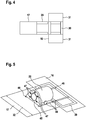
- Fig. 5 shows a transmission 22 with a gearbox 45; the transmission 22 is suspended via suspension elements 47 on the gearbox 45.
- the layouts of the machine support module 17 and the electric module 16 are shown; the Geretespant 45 does not extend over the entire transverse extent 32 of the machine frame module.
- the transmission can be pulled via a rail system 46 from the machine support module 17 in the electric module 16; in the electric module, the transmission can be positioned over the component carrier 39.
- Fig. 6 shows a perspective view of the wind turbine with a tower 15, a machine support module 17 and an electric module 16.
- the electric module 16 is half open and shown empty.
- the roof 38 of the electric module 16 consists of several segments; the middle segment is shifted against the outer segments and releases an opening.
- the generator 23 and the transformer 25 rest, shown schematically, on the component carrier 39.
- the component carrier 39 can be connected via four bolts 40 to the central frame 30; the central frame 30 has on each side two openings 37.
- the component carrier rests on a lifting platform 41, wherein the lifting platform 41 via ropes 42 with the central frame 30th of the electric module 16 is connected.
- the lifting platform 41 is part of the system for servicing the nacelle component according to the invention. With winches 43 of the lifting platform 41, the free length of the cables 42 can be changed, whereby a vertical method of the lifting platform 41 is effected. As a result, a transport of the component carrier 39 and the elements generator 23 and transformer 25 between the foot of the tower 15 and the electric module 16 is made possible.
- Fig. 7 shows a lifting platform 41 with winches 43, which carries a service crane 44.
- the component carrier 41 and the crane 44 are elements of the system for servicing a nacelle component according to the invention.
- the component carrier 41 loaded with the service crane 44 can be connected to the central frame 30 of the electric module 16 via the cables 42 of the winches 43.
- the in Fig. 7 shown component carrier 41 may instead of the in Fig. 6 shown component carrier are moved vertically relative to the nacelle component; the in Fig. 7 shown service crane 44 may instead of the in Fig. 6 shown elements generator 23 and transformer 25 are transported between the bottom of the tower 15 and the nacelle component.
- the service crane 44 When the service crane 44 is connected to the electric module 16, it can be used to move heavy components such as the transmission or generator within the nacelle.
- the service crane 44 can also be used to lift other components of the nacelle or tools needed for the maintenance of the wind turbine, for example from the base of the tower to the nacelle.
- the machine support module 17 and the electric module 16 can be brought into a preassembled state.
- the machine carrier module 17 is then equipped with the rotor shaft 20, the gear 22 and the turntable 12.
- the electric module 16 is connected to the generator 23, the inverter 24, the transformer 25 and the control cabinets 26 equipped.
- the generator 23, the inverter 24 and the transformer 25 are electrically connected to each other and connected to the control cabinets 26, that already in the factory a complete functional verification of the components of the electric module 16 can be performed.
- Both modules 16, 17 have a width of 4 m, a height of not more than 4 m and a length between 7 m and 10 m. Given these dimensions, a road-bound transport with manageable effort is possible.
- the machine support module 17 and the electric module 16 are connected to each other by screws and the input shaft 28 of the generator 23 is connected to the fast shaft of the transmission 22.
- the nacelle component is then in an assembled state. After attaching other elements, such as a housing, the finished nacelle 14 is raised and placed on top of the tower 15. Depending on the dimensions of the wind turbine and the availability of cranes, it may be more economical to lift the gondola separately in individual modules on the tower and connect there.
- the individual modules, machine carrier module 17 and electric module 16 can also be lifted piece by piece in elements on the tower and mounted there.
- An azimuth bearing is mounted between the nacelle 14 and the tower 15 so that the nacelle 14 can rotate relative to the tower 15.
- a medium voltage cable is fed from the transformer 25 via the machine support module 16 and the interior of the tower 15 to the tower base and connected there to a connection network.
- Fig. 8 a first deployment condition is shown in which the wind turbine component can be brought to the ground.
- the machine carrier 60 is raised with the side walls of the housing to the upper end of the tower 15.
- the electric module 63 is raised with the electrical components.
- the rotor is added as a whole or in components.
- a second set-up condition is shown in which the wind turbine component can be brought to the ground.
- the first transport unit is formed by the machine carrier 60 with the side walls of the housing and the electric module 63.
- the second transport unit is formed by the driveline 61 with the roof 62 of the enclosure. Subsequently, the rotor is added as a whole or in components.
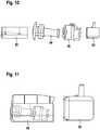
- the first transport unit is formed by the machine carrier 60 with the side walls of the housing.
- the second transport unit is formed by the majority driveline 64 without the transmission 65.
- the transmission 65 forms the third transport unit.
- the electric module 63 forms the fourth transport unit. Subsequently, the rotor is added as a whole or in components.
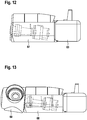
- FIG. 12 shows a fourth construction state in which the first transport unit 66 includes the machine frame 60, the driveline 61, and the enclosure.
- the electric module 63 forms the second transport unit. Subsequently, the rotor is added as a whole or in components.
- the first transport unit 67 comprises the entire nacelle with the machine carrier, the drive train, the housing and the electric module. Subsequently, the rotor is added as a whole or in components.
- the nacelle comprises the rotor hub 69.
- the rotor blades are successively connected to the rotor hub 69, wherein each of the rotor blades forms a further transport unit.
Landscapes
- Engineering & Computer Science (AREA)
- Life Sciences & Earth Sciences (AREA)
- Sustainable Development (AREA)
- Sustainable Energy (AREA)
- Chemical & Material Sciences (AREA)
- Combustion & Propulsion (AREA)
- Mechanical Engineering (AREA)
- General Engineering & Computer Science (AREA)
- Power Engineering (AREA)
- Wind Motors (AREA)
Applications Claiming Priority (1)
| Application Number | Priority Date | Filing Date | Title |
|---|---|---|---|
| DE102017004800.2A DE102017004800A1 (de) | 2017-05-18 | 2017-05-18 | Gondelkomponente für eine Windenergieanlage und Verfahren zum Montieren einer Gondelkomponente |
Publications (2)
| Publication Number | Publication Date |
|---|---|
| EP3406898A1 true EP3406898A1 (fr) | 2018-11-28 |
| EP3406898B1 EP3406898B1 (fr) | 2021-11-24 |
Family
ID=62196428
Family Applications (1)
| Application Number | Title | Priority Date | Filing Date |
|---|---|---|---|
| EP18172806.4A Active EP3406898B1 (fr) | 2017-05-18 | 2018-05-17 | Composant de nacelle pour une éolienne et procédé de montage d'un composant de nacelle |
Country Status (4)
| Country | Link |
|---|---|
| US (1) | US10781798B2 (fr) |
| EP (1) | EP3406898B1 (fr) |
| CN (1) | CN108953063B (fr) |
| DE (1) | DE102017004800A1 (fr) |
Cited By (4)
| Publication number | Priority date | Publication date | Assignee | Title |
|---|---|---|---|---|
| EP3786448A1 (fr) * | 2019-08-29 | 2021-03-03 | General Electric Company | Procédé de montage d'une nacelle d'une éolienne et d'assemblage d'un ensemble de pièces d'une éolienne |
| US11300105B2 (en) | 2017-08-29 | 2022-04-12 | Vestas Wind Systems A/S | Wind turbine with a movable container housing a hoisting mechanism |
| CN114837907A (zh) * | 2022-01-25 | 2022-08-02 | 北京三力新能科技有限公司 | 一种风力发电机组的机舱、机舱吊装方法及风力发电机组 |
| EP4060189B1 (fr) | 2021-03-18 | 2025-07-02 | Nordex Energy SE & Co. KG | Agencement de support de boîte de vitesses pour une éolienne et éolienne |
Families Citing this family (11)
| Publication number | Priority date | Publication date | Assignee | Title |
|---|---|---|---|---|
| EP3736441B1 (fr) * | 2019-05-09 | 2021-07-14 | Siemens Gamesa Renewable Energy A/S | Procédé de production d'une éolienne, structure de nacelle et éolienne |
| JP7546052B2 (ja) * | 2019-11-22 | 2024-09-05 | ヴェスタス ウィンド システムズ エー/エス | 風力タービン用ナセル |
| CN114945751B (zh) * | 2019-12-19 | 2025-07-22 | 维斯塔斯风力系统有限公司 | 用于安装或移除风力涡轮机部件的方法 |
| EP3875758B1 (fr) * | 2020-03-06 | 2024-01-03 | Siemens Gamesa Renewable Energy A/S | Éolienne comprenant un module fonctionnel amovible et procédé de couplage d'un module fonctionnel sur une éolienne |
| EP3896280A1 (fr) * | 2020-04-16 | 2021-10-20 | Siemens Gamesa Renewable Energy Innovation & Technology S.L. | Agencement de levage de turbine éolienne |
| EP4150204B1 (fr) * | 2020-05-15 | 2024-04-24 | Vestas Wind Systems A/S | Nacelle pour éolienne et procédé pour transférer des composants |
| CN112555106A (zh) * | 2020-11-23 | 2021-03-26 | 国网浙江省电力有限公司磐安县供电公司 | 一种方便拆装的风电机组塔筒散热结构 |
| DK181017B1 (en) | 2021-05-03 | 2022-09-26 | Liftra Ip Aps | Base for supporting a portable crane |
| ES3009723T3 (en) | 2021-05-26 | 2025-03-31 | Vestas Wind Sys As | Wind turbine with auxiliary units |
| DE102021208984A1 (de) * | 2021-08-17 | 2023-02-23 | Zf Friedrichshafen Ag | Montage- und Demontagevorrichtung |
| EP4431728A1 (fr) | 2023-03-16 | 2024-09-18 | Siemens Gamesa Renewable Energy Innovation & Technology S.L. | Nacelle comprenant une unité inférieure |
Citations (7)
| Publication number | Priority date | Publication date | Assignee | Title |
|---|---|---|---|---|
| DE10013442C1 (de) * | 2000-03-17 | 2001-10-31 | Tacke Windenergie Gmbh | Windkraftanlage |
| US20030071469A1 (en) * | 2001-04-20 | 2003-04-17 | Markus Becker | Wind power plant with a movable container |
| US20090129931A1 (en) * | 2007-11-21 | 2009-05-21 | Siemens Aktiengesellschaft | Module of a nacelle of a wind turbine, nacelle of a wind turbine, wind turbineand method for the assembly of a nacelle of a wind turbine |
| DE102007062622A1 (de) * | 2007-12-22 | 2009-06-25 | Nordex Energy Gmbh | Windenergieanlage mit einem Gehäusemodul zur Aufnahme elektrischer Betriebsmittel |
| US20130234443A1 (en) * | 2011-09-07 | 2013-09-12 | Wilic S.Ar.L. | Wind power turbine auxiliary unit |
| EP2759701A1 (fr) * | 2011-09-22 | 2014-07-30 | Mitsubishi Heavy Industries, Ltd. | Dispositif de génération d'énergie de type à énergie renouvelable |
| WO2016116112A1 (fr) * | 2015-01-22 | 2016-07-28 | Vestas Wind Systems A/S | Nacelle d'éolienne |
Family Cites Families (15)
| Publication number | Priority date | Publication date | Assignee | Title |
|---|---|---|---|---|
| DE19955516C1 (de) * | 1999-11-18 | 2001-12-20 | Tacke Windenergie Gmbh | Windkraftanlage und Verfahren zum Aus- und Einbau der Hauptkomponenten des Maschinengehäuses einer Windkraftanlage |
| CN101389855B (zh) * | 2006-02-27 | 2011-12-07 | 埃科泰克尼亚可再生能源有限公司 | 用于在风轮机上执行操作的方法和系统 |
| ES2318963B1 (es) * | 2006-05-30 | 2010-02-04 | GAMESA INNOVATION & TECHNOLOGY, S.L. | Utilizacion de laminacion de grano orientado en un generador de turbina eolica. |
| JP4959439B2 (ja) * | 2007-06-22 | 2012-06-20 | 三菱重工業株式会社 | 風力発電装置 |
| ES2566971T3 (es) * | 2009-02-05 | 2016-04-18 | Vestas Wind Systems A/S | Turbina eólica que tiene electrónica de potencia en la góndola |
| DK2372150T3 (da) * | 2010-03-29 | 2014-03-17 | Alstom Renovables Espana Sl | Vindmølle |
| US9309868B2 (en) * | 2010-10-18 | 2016-04-12 | Vestas Wind Systems A/S | Wind turbine power transmission system and method of installing a wind farm including same |
| US8147183B2 (en) * | 2010-12-30 | 2012-04-03 | General Electric Company | Drivetrain for generator in wind turbine |
| IN2012DN03058A (fr) * | 2011-04-05 | 2015-07-31 | Mitsubishi Heavy Ind Ltd | |
| US8500400B2 (en) * | 2011-09-20 | 2013-08-06 | General Electric Company | Component handling system for use in wind turbines and methods of positioning a drive train component |
| DK2573387T4 (da) | 2011-09-22 | 2020-04-27 | Siemens Gamesa Renewable Energy As | Nacelle til en vindmølle |
| ITMI20112323A1 (it) * | 2011-12-20 | 2013-06-21 | Wilic Sarl | Impianto eolico per la generazione di energia elettrica |
| US10519937B2 (en) * | 2013-10-14 | 2019-12-31 | Vestas Wind Systems A/S | Electrical connector for a wind turbine |
| CN104810942B (zh) * | 2015-04-15 | 2017-03-01 | 新疆金风科技股份有限公司 | 永磁直驱风力发电机、系统及其定子 |
| CN206000685U (zh) * | 2016-08-10 | 2017-03-08 | 青岛华创风能有限公司 | 机舱铸造底架 |
-
2017
- 2017-05-18 DE DE102017004800.2A patent/DE102017004800A1/de not_active Withdrawn
-
2018
- 2018-05-17 EP EP18172806.4A patent/EP3406898B1/fr active Active
- 2018-05-18 US US15/983,192 patent/US10781798B2/en active Active
- 2018-05-18 CN CN201810479294.9A patent/CN108953063B/zh active Active
Patent Citations (7)
| Publication number | Priority date | Publication date | Assignee | Title |
|---|---|---|---|---|
| DE10013442C1 (de) * | 2000-03-17 | 2001-10-31 | Tacke Windenergie Gmbh | Windkraftanlage |
| US20030071469A1 (en) * | 2001-04-20 | 2003-04-17 | Markus Becker | Wind power plant with a movable container |
| US20090129931A1 (en) * | 2007-11-21 | 2009-05-21 | Siemens Aktiengesellschaft | Module of a nacelle of a wind turbine, nacelle of a wind turbine, wind turbineand method for the assembly of a nacelle of a wind turbine |
| DE102007062622A1 (de) * | 2007-12-22 | 2009-06-25 | Nordex Energy Gmbh | Windenergieanlage mit einem Gehäusemodul zur Aufnahme elektrischer Betriebsmittel |
| US20130234443A1 (en) * | 2011-09-07 | 2013-09-12 | Wilic S.Ar.L. | Wind power turbine auxiliary unit |
| EP2759701A1 (fr) * | 2011-09-22 | 2014-07-30 | Mitsubishi Heavy Industries, Ltd. | Dispositif de génération d'énergie de type à énergie renouvelable |
| WO2016116112A1 (fr) * | 2015-01-22 | 2016-07-28 | Vestas Wind Systems A/S | Nacelle d'éolienne |
Cited By (6)
| Publication number | Priority date | Publication date | Assignee | Title |
|---|---|---|---|---|
| US11300105B2 (en) | 2017-08-29 | 2022-04-12 | Vestas Wind Systems A/S | Wind turbine with a movable container housing a hoisting mechanism |
| EP3676492B1 (fr) * | 2017-08-29 | 2024-02-14 | Vestas Wind Systems A/S | Éolienne dotée d'un contenant mobile logeant un mécanisme de levage |
| EP3786448A1 (fr) * | 2019-08-29 | 2021-03-03 | General Electric Company | Procédé de montage d'une nacelle d'une éolienne et d'assemblage d'un ensemble de pièces d'une éolienne |
| US11353007B2 (en) | 2019-08-29 | 2022-06-07 | General Electric Company | Method of mounting a nacelle of a wind turbine and assembling set of parts of a wind turbine |
| EP4060189B1 (fr) | 2021-03-18 | 2025-07-02 | Nordex Energy SE & Co. KG | Agencement de support de boîte de vitesses pour une éolienne et éolienne |
| CN114837907A (zh) * | 2022-01-25 | 2022-08-02 | 北京三力新能科技有限公司 | 一种风力发电机组的机舱、机舱吊装方法及风力发电机组 |
Also Published As
| Publication number | Publication date |
|---|---|
| DE102017004800A1 (de) | 2018-11-22 |
| EP3406898B1 (fr) | 2021-11-24 |
| US10781798B2 (en) | 2020-09-22 |
| CN108953063B (zh) | 2021-05-28 |
| US20180335023A1 (en) | 2018-11-22 |
| CN108953063A (zh) | 2018-12-07 |
Similar Documents
| Publication | Publication Date | Title |
|---|---|---|
| EP3406898B1 (fr) | Composant de nacelle pour une éolienne et procédé de montage d'un composant de nacelle | |
| DE10013442C1 (de) | Windkraftanlage | |
| EP1483526B1 (fr) | Aeronef comportant une pluralite de rotors de sustantation et de poussee | |
| DE60011737T3 (de) | Methode zum Montieren der Komponenten einer Windkraftanlage | |
| EP1134410B1 (fr) | Eolienne marine | |
| EP2764237B1 (fr) | Procédé et dispositif de montage d'un rotor d'une éolienne | |
| EP1251269A2 (fr) | Eolienne avec conteneur mobile | |
| DE102007062622A1 (de) | Windenergieanlage mit einem Gehäusemodul zur Aufnahme elektrischer Betriebsmittel | |
| EP2014912A2 (fr) | Eolienne dotée d'une nacelle et procédé de fabrication d'une telle éolienne | |
| DE102018005852A1 (de) | Montageverfahren und Montagesystem für einen Schwingungsdämpfer eines Windenergieanlagenturms | |
| EP3710694A1 (fr) | Cadre de bride et ensemble de montage pour le pré-montage et/ou le transport et/ou le montage d'un segment de tour destiné à une éolienne et procede | |
| DE4106976A1 (de) | Windkraftanlagen | |
| EP2740928A1 (fr) | Eolienne | |
| DE19636240A1 (de) | Maste für Windkraftanlagen | |
| WO1998009072A9 (fr) | Pylones pour eolienne | |
| DE102019109204A1 (de) | Traverse | |
| EP1577550B1 (fr) | Procédé pour rendre disponible un treuil sur une éolienne et dispositif pour réaliser ce procédé | |
| EP4230565A1 (fr) | Dispositif de libération pour un appareil de levage-inclinaison pour libérer l'appareil de levage-inclinaison d'un segment de générateur, appareil de levage-inclinaison pour levage et inclinaison d'un segment de générateur, procédé de levage et d'inclinaison d'un segment de générateur et procédé de montage d'un appareil de levage-inclinaison sur un segment générateur démonté | |
| DE202007019340U1 (de) | Windenergieanlage mit einem Gehäusemodul zur Aufnahme elektrischer Betriebsmittel | |
| WO2025003294A1 (fr) | Plate-forme et son procédé de montage | |
| EP3242013A1 (fr) | Éolienne comprenant un dispositif destine a faire tourner une nacelle de l'eolienne et procede de montage d'un dispositif destine a faire tourner une nacelle | |
| EP3581794B1 (fr) | Système de montage et procédé de montage d'un rotor en étoile pour une éolienne | |
| DE202020003848U1 (de) | Vorrichtung zur Gewinnung von elektrischer Energie sowohl aus Windkraft als auch aus Sonnenlicht | |
| EP3255227A1 (fr) | Construction d'aide au montage et procédé de changement d'un élément de structure porteuse | |
| EP0621228A1 (fr) | Procédé pour la production et le montage de grues ainsi que la grue, en particulier: grue de bord |
Legal Events
| Date | Code | Title | Description |
|---|---|---|---|
| PUAI | Public reference made under article 153(3) epc to a published international application that has entered the european phase |
Free format text: ORIGINAL CODE: 0009012 |
|
| STAA | Information on the status of an ep patent application or granted ep patent |
Free format text: STATUS: THE APPLICATION HAS BEEN PUBLISHED |
|
| AK | Designated contracting states |
Kind code of ref document: A1 Designated state(s): AL AT BE BG CH CY CZ DE DK EE ES FI FR GB GR HR HU IE IS IT LI LT LU LV MC MK MT NL NO PL PT RO RS SE SI SK SM TR |
|
| AX | Request for extension of the european patent |
Extension state: BA ME |
|
| STAA | Information on the status of an ep patent application or granted ep patent |
Free format text: STATUS: REQUEST FOR EXAMINATION WAS MADE |
|
| 17P | Request for examination filed |
Effective date: 20190527 |
|
| RBV | Designated contracting states (corrected) |
Designated state(s): AL AT BE BG CH CY CZ DE DK EE ES FI FR GB GR HR HU IE IS IT LI LT LU LV MC MK MT NL NO PL PT RO RS SE SI SK SM TR |
|
| STAA | Information on the status of an ep patent application or granted ep patent |
Free format text: STATUS: EXAMINATION IS IN PROGRESS |
|
| 17Q | First examination report despatched |
Effective date: 20200529 |
|
| REG | Reference to a national code |
Ref country code: DE Ref legal event code: R079 Ref document number: 502018007939 Country of ref document: DE Free format text: PREVIOUS MAIN CLASS: F03D0080000000 Ipc: F03D0080800000 |
|
| RIC1 | Information provided on ipc code assigned before grant |
Ipc: F03D 80/80 20160101AFI20210705BHEP Ipc: F03D 80/50 20160101ALI20210705BHEP Ipc: F03D 13/10 20160101ALI20210705BHEP |
|
| GRAP | Despatch of communication of intention to grant a patent |
Free format text: ORIGINAL CODE: EPIDOSNIGR1 |
|
| STAA | Information on the status of an ep patent application or granted ep patent |
Free format text: STATUS: GRANT OF PATENT IS INTENDED |
|
| INTG | Intention to grant announced |
Effective date: 20210813 |
|
| GRAS | Grant fee paid |
Free format text: ORIGINAL CODE: EPIDOSNIGR3 |
|
| GRAA | (expected) grant |
Free format text: ORIGINAL CODE: 0009210 |
|
| STAA | Information on the status of an ep patent application or granted ep patent |
Free format text: STATUS: THE PATENT HAS BEEN GRANTED |
|
| AK | Designated contracting states |
Kind code of ref document: B1 Designated state(s): AL AT BE BG CH CY CZ DE DK EE ES FI FR GB GR HR HU IE IS IT LI LT LU LV MC MK MT NL NO PL PT RO RS SE SI SK SM TR |
|
| REG | Reference to a national code |
Ref country code: GB Ref legal event code: FG4D Free format text: NOT ENGLISH |
|
| REG | Reference to a national code |
Ref country code: AT Ref legal event code: REF Ref document number: 1450062 Country of ref document: AT Kind code of ref document: T Effective date: 20211215 |
|
| REG | Reference to a national code |
Ref country code: DE Ref legal event code: R096 Ref document number: 502018007939 Country of ref document: DE |
|
| REG | Reference to a national code |
Ref country code: IE Ref legal event code: FG4D Free format text: LANGUAGE OF EP DOCUMENT: GERMAN |
|
| RAP2 | Party data changed (patent owner data changed or rights of a patent transferred) |
Owner name: SIEMENS GAMESA RENEWABLE ENERGY SERVICE GMBH |
|
| REG | Reference to a national code |
Ref country code: LT Ref legal event code: MG9D |
|
| REG | Reference to a national code |
Ref country code: NL Ref legal event code: MP Effective date: 20211124 |
|
| PG25 | Lapsed in a contracting state [announced via postgrant information from national office to epo] |
Ref country code: RS Free format text: LAPSE BECAUSE OF FAILURE TO SUBMIT A TRANSLATION OF THE DESCRIPTION OR TO PAY THE FEE WITHIN THE PRESCRIBED TIME-LIMIT Effective date: 20211124 Ref country code: LT Free format text: LAPSE BECAUSE OF FAILURE TO SUBMIT A TRANSLATION OF THE DESCRIPTION OR TO PAY THE FEE WITHIN THE PRESCRIBED TIME-LIMIT Effective date: 20211124 Ref country code: FI Free format text: LAPSE BECAUSE OF FAILURE TO SUBMIT A TRANSLATION OF THE DESCRIPTION OR TO PAY THE FEE WITHIN THE PRESCRIBED TIME-LIMIT Effective date: 20211124 Ref country code: BG Free format text: LAPSE BECAUSE OF FAILURE TO SUBMIT A TRANSLATION OF THE DESCRIPTION OR TO PAY THE FEE WITHIN THE PRESCRIBED TIME-LIMIT Effective date: 20220224 |
|
| REG | Reference to a national code |
Ref country code: GB Ref legal event code: 732E Free format text: REGISTERED BETWEEN 20220407 AND 20220413 |
|
| PG25 | Lapsed in a contracting state [announced via postgrant information from national office to epo] |
Ref country code: IS Free format text: LAPSE BECAUSE OF FAILURE TO SUBMIT A TRANSLATION OF THE DESCRIPTION OR TO PAY THE FEE WITHIN THE PRESCRIBED TIME-LIMIT Effective date: 20220324 Ref country code: SE Free format text: LAPSE BECAUSE OF FAILURE TO SUBMIT A TRANSLATION OF THE DESCRIPTION OR TO PAY THE FEE WITHIN THE PRESCRIBED TIME-LIMIT Effective date: 20211124 Ref country code: PT Free format text: LAPSE BECAUSE OF FAILURE TO SUBMIT A TRANSLATION OF THE DESCRIPTION OR TO PAY THE FEE WITHIN THE PRESCRIBED TIME-LIMIT Effective date: 20220324 Ref country code: PL Free format text: LAPSE BECAUSE OF FAILURE TO SUBMIT A TRANSLATION OF THE DESCRIPTION OR TO PAY THE FEE WITHIN THE PRESCRIBED TIME-LIMIT Effective date: 20211124 Ref country code: NO Free format text: LAPSE BECAUSE OF FAILURE TO SUBMIT A TRANSLATION OF THE DESCRIPTION OR TO PAY THE FEE WITHIN THE PRESCRIBED TIME-LIMIT Effective date: 20220224 Ref country code: NL Free format text: LAPSE BECAUSE OF FAILURE TO SUBMIT A TRANSLATION OF THE DESCRIPTION OR TO PAY THE FEE WITHIN THE PRESCRIBED TIME-LIMIT Effective date: 20211124 Ref country code: LV Free format text: LAPSE BECAUSE OF FAILURE TO SUBMIT A TRANSLATION OF THE DESCRIPTION OR TO PAY THE FEE WITHIN THE PRESCRIBED TIME-LIMIT Effective date: 20211124 Ref country code: HR Free format text: LAPSE BECAUSE OF FAILURE TO SUBMIT A TRANSLATION OF THE DESCRIPTION OR TO PAY THE FEE WITHIN THE PRESCRIBED TIME-LIMIT Effective date: 20211124 Ref country code: GR Free format text: LAPSE BECAUSE OF FAILURE TO SUBMIT A TRANSLATION OF THE DESCRIPTION OR TO PAY THE FEE WITHIN THE PRESCRIBED TIME-LIMIT Effective date: 20220225 Ref country code: ES Free format text: LAPSE BECAUSE OF FAILURE TO SUBMIT A TRANSLATION OF THE DESCRIPTION OR TO PAY THE FEE WITHIN THE PRESCRIBED TIME-LIMIT Effective date: 20211124 |
|
| REG | Reference to a national code |
Ref country code: DE Ref legal event code: R081 Ref document number: 502018007939 Country of ref document: DE Owner name: SIEMENS GAMESA RENEWABLE ENERGY SERVICE GMBH, DE Free format text: FORMER OWNER: SENVION GMBH, 22297 HAMBURG, DE |
|
| PG25 | Lapsed in a contracting state [announced via postgrant information from national office to epo] |
Ref country code: SM Free format text: LAPSE BECAUSE OF FAILURE TO SUBMIT A TRANSLATION OF THE DESCRIPTION OR TO PAY THE FEE WITHIN THE PRESCRIBED TIME-LIMIT Effective date: 20211124 Ref country code: SK Free format text: LAPSE BECAUSE OF FAILURE TO SUBMIT A TRANSLATION OF THE DESCRIPTION OR TO PAY THE FEE WITHIN THE PRESCRIBED TIME-LIMIT Effective date: 20211124 Ref country code: RO Free format text: LAPSE BECAUSE OF FAILURE TO SUBMIT A TRANSLATION OF THE DESCRIPTION OR TO PAY THE FEE WITHIN THE PRESCRIBED TIME-LIMIT Effective date: 20211124 Ref country code: EE Free format text: LAPSE BECAUSE OF FAILURE TO SUBMIT A TRANSLATION OF THE DESCRIPTION OR TO PAY THE FEE WITHIN THE PRESCRIBED TIME-LIMIT Effective date: 20211124 Ref country code: DK Free format text: LAPSE BECAUSE OF FAILURE TO SUBMIT A TRANSLATION OF THE DESCRIPTION OR TO PAY THE FEE WITHIN THE PRESCRIBED TIME-LIMIT Effective date: 20211124 Ref country code: CZ Free format text: LAPSE BECAUSE OF FAILURE TO SUBMIT A TRANSLATION OF THE DESCRIPTION OR TO PAY THE FEE WITHIN THE PRESCRIBED TIME-LIMIT Effective date: 20211124 |
|
| REG | Reference to a national code |
Ref country code: DE Ref legal event code: R097 Ref document number: 502018007939 Country of ref document: DE |
|
| PLBE | No opposition filed within time limit |
Free format text: ORIGINAL CODE: 0009261 |
|
| STAA | Information on the status of an ep patent application or granted ep patent |
Free format text: STATUS: NO OPPOSITION FILED WITHIN TIME LIMIT |
|
| PG25 | Lapsed in a contracting state [announced via postgrant information from national office to epo] |
Ref country code: AL Free format text: LAPSE BECAUSE OF FAILURE TO SUBMIT A TRANSLATION OF THE DESCRIPTION OR TO PAY THE FEE WITHIN THE PRESCRIBED TIME-LIMIT Effective date: 20211124 |
|
| 26N | No opposition filed |
Effective date: 20220825 |
|
| PG25 | Lapsed in a contracting state [announced via postgrant information from national office to epo] |
Ref country code: SI Free format text: LAPSE BECAUSE OF FAILURE TO SUBMIT A TRANSLATION OF THE DESCRIPTION OR TO PAY THE FEE WITHIN THE PRESCRIBED TIME-LIMIT Effective date: 20211124 |
|
| REG | Reference to a national code |
Ref country code: CH Ref legal event code: PL |
|
| REG | Reference to a national code |
Ref country code: BE Ref legal event code: MM Effective date: 20220531 |
|
| PG25 | Lapsed in a contracting state [announced via postgrant information from national office to epo] |
Ref country code: MC Free format text: LAPSE BECAUSE OF FAILURE TO SUBMIT A TRANSLATION OF THE DESCRIPTION OR TO PAY THE FEE WITHIN THE PRESCRIBED TIME-LIMIT Effective date: 20211124 Ref country code: LU Free format text: LAPSE BECAUSE OF NON-PAYMENT OF DUE FEES Effective date: 20220517 Ref country code: LI Free format text: LAPSE BECAUSE OF NON-PAYMENT OF DUE FEES Effective date: 20220531 Ref country code: CH Free format text: LAPSE BECAUSE OF NON-PAYMENT OF DUE FEES Effective date: 20220531 |
|
| PG25 | Lapsed in a contracting state [announced via postgrant information from national office to epo] |
Ref country code: IE Free format text: LAPSE BECAUSE OF NON-PAYMENT OF DUE FEES Effective date: 20220517 |
|
| PG25 | Lapsed in a contracting state [announced via postgrant information from national office to epo] |
Ref country code: IT Free format text: LAPSE BECAUSE OF FAILURE TO SUBMIT A TRANSLATION OF THE DESCRIPTION OR TO PAY THE FEE WITHIN THE PRESCRIBED TIME-LIMIT Effective date: 20211124 Ref country code: BE Free format text: LAPSE BECAUSE OF NON-PAYMENT OF DUE FEES Effective date: 20220531 |
|
| PG25 | Lapsed in a contracting state [announced via postgrant information from national office to epo] |
Ref country code: HU Free format text: LAPSE BECAUSE OF FAILURE TO SUBMIT A TRANSLATION OF THE DESCRIPTION OR TO PAY THE FEE WITHIN THE PRESCRIBED TIME-LIMIT; INVALID AB INITIO Effective date: 20180517 |
|
| PG25 | Lapsed in a contracting state [announced via postgrant information from national office to epo] |
Ref country code: MK Free format text: LAPSE BECAUSE OF FAILURE TO SUBMIT A TRANSLATION OF THE DESCRIPTION OR TO PAY THE FEE WITHIN THE PRESCRIBED TIME-LIMIT Effective date: 20211124 Ref country code: CY Free format text: LAPSE BECAUSE OF FAILURE TO SUBMIT A TRANSLATION OF THE DESCRIPTION OR TO PAY THE FEE WITHIN THE PRESCRIBED TIME-LIMIT Effective date: 20211124 |
|
| REG | Reference to a national code |
Ref country code: AT Ref legal event code: MM01 Ref document number: 1450062 Country of ref document: AT Kind code of ref document: T Effective date: 20230517 |
|
| PG25 | Lapsed in a contracting state [announced via postgrant information from national office to epo] |
Ref country code: AT Free format text: LAPSE BECAUSE OF NON-PAYMENT OF DUE FEES Effective date: 20230517 |
|
| PG25 | Lapsed in a contracting state [announced via postgrant information from national office to epo] |
Ref country code: AT Free format text: LAPSE BECAUSE OF NON-PAYMENT OF DUE FEES Effective date: 20230517 |
|
| PG25 | Lapsed in a contracting state [announced via postgrant information from national office to epo] |
Ref country code: MT Free format text: LAPSE BECAUSE OF FAILURE TO SUBMIT A TRANSLATION OF THE DESCRIPTION OR TO PAY THE FEE WITHIN THE PRESCRIBED TIME-LIMIT Effective date: 20211124 |
|
| PGFP | Annual fee paid to national office [announced via postgrant information from national office to epo] |
Ref country code: DE Payment date: 20250528 Year of fee payment: 8 |
|
| PGFP | Annual fee paid to national office [announced via postgrant information from national office to epo] |
Ref country code: FR Payment date: 20250526 Year of fee payment: 8 |
|
| PG25 | Lapsed in a contracting state [announced via postgrant information from national office to epo] |
Ref country code: TR Free format text: LAPSE BECAUSE OF FAILURE TO SUBMIT A TRANSLATION OF THE DESCRIPTION OR TO PAY THE FEE WITHIN THE PRESCRIBED TIME-LIMIT Effective date: 20211124 |
|
| PGFP | Annual fee paid to national office [announced via postgrant information from national office to epo] |
Ref country code: GB Payment date: 20260323 Year of fee payment: 9 |
|
| PGFP | Annual fee paid to national office [announced via postgrant information from national office to epo] |
Ref country code: AT Payment date: 20260410 Year of fee payment: 5 |