EP3406975B1 - Decken-klimatisierungsvorrichtung mit tragkonstruktion - Google Patents
Decken-klimatisierungsvorrichtung mit tragkonstruktion Download PDFInfo
- Publication number
- EP3406975B1 EP3406975B1 EP18171325.6A EP18171325A EP3406975B1 EP 3406975 B1 EP3406975 B1 EP 3406975B1 EP 18171325 A EP18171325 A EP 18171325A EP 3406975 B1 EP3406975 B1 EP 3406975B1
- Authority
- EP
- European Patent Office
- Prior art keywords
- profile
- air conditioning
- conditioning device
- ceiling air
- profile element
- Prior art date
- Legal status (The legal status is an assumption and is not a legal conclusion. Google has not performed a legal analysis and makes no representation as to the accuracy of the status listed.)
- Active
Links
Images



Classifications
-
- F—MECHANICAL ENGINEERING; LIGHTING; HEATING; WEAPONS; BLASTING
- F24—HEATING; RANGES; VENTILATING
- F24F—AIR-CONDITIONING; AIR-HUMIDIFICATION; VENTILATION; USE OF AIR CURRENTS FOR SCREENING
- F24F1/00—Room units for air-conditioning, e.g. separate or self-contained units or units receiving primary air from a central station
- F24F1/0007—Indoor units, e.g. fan coil units
-
- E—FIXED CONSTRUCTIONS
- E04—BUILDING
- E04B—GENERAL BUILDING CONSTRUCTIONS; WALLS, e.g. PARTITIONS; ROOFS; FLOORS; CEILINGS; INSULATION OR OTHER PROTECTION OF BUILDINGS
- E04B9/00—Ceilings; Construction of ceilings, e.g. false ceilings; Ceiling construction with regard to insulation
- E04B9/02—Ceilings; Construction of ceilings, e.g. false ceilings; Ceiling construction with regard to insulation having means for ventilation or vapour discharge
-
- F—MECHANICAL ENGINEERING; LIGHTING; HEATING; WEAPONS; BLASTING
- F24—HEATING; RANGES; VENTILATING
- F24F—AIR-CONDITIONING; AIR-HUMIDIFICATION; VENTILATION; USE OF AIR CURRENTS FOR SCREENING
- F24F1/00—Room units for air-conditioning, e.g. separate or self-contained units or units receiving primary air from a central station
-
- F—MECHANICAL ENGINEERING; LIGHTING; HEATING; WEAPONS; BLASTING
- F24—HEATING; RANGES; VENTILATING
- F24F—AIR-CONDITIONING; AIR-HUMIDIFICATION; VENTILATION; USE OF AIR CURRENTS FOR SCREENING
- F24F1/00—Room units for air-conditioning, e.g. separate or self-contained units or units receiving primary air from a central station
- F24F1/0007—Indoor units, e.g. fan coil units
- F24F1/00075—Indoor units, e.g. fan coil units receiving air from a central station
-
- F—MECHANICAL ENGINEERING; LIGHTING; HEATING; WEAPONS; BLASTING
- F24—HEATING; RANGES; VENTILATING
- F24F—AIR-CONDITIONING; AIR-HUMIDIFICATION; VENTILATION; USE OF AIR CURRENTS FOR SCREENING
- F24F13/00—Details common to, or for air-conditioning, air-humidification, ventilation or use of air currents for screening
- F24F13/02—Ducting arrangements
- F24F13/06—Outlets for directing or distributing air into rooms or spaces, e.g. ceiling air diffuser
- F24F13/072—Outlets for directing or distributing air into rooms or spaces, e.g. ceiling air diffuser of elongated shape, e.g. between ceiling panels
-
- F—MECHANICAL ENGINEERING; LIGHTING; HEATING; WEAPONS; BLASTING
- F24—HEATING; RANGES; VENTILATING
- F24F—AIR-CONDITIONING; AIR-HUMIDIFICATION; VENTILATION; USE OF AIR CURRENTS FOR SCREENING
- F24F13/00—Details common to, or for air-conditioning, air-humidification, ventilation or use of air currents for screening
- F24F13/30—Arrangement or mounting of heat-exchangers
-
- F—MECHANICAL ENGINEERING; LIGHTING; HEATING; WEAPONS; BLASTING
- F24—HEATING; RANGES; VENTILATING
- F24F—AIR-CONDITIONING; AIR-HUMIDIFICATION; VENTILATION; USE OF AIR CURRENTS FOR SCREENING
- F24F5/00—Air-conditioning systems or apparatus not covered by F24F1/00 or F24F3/00, e.g. using solar heat or combined with household units such as an oven or water heater
- F24F5/0089—Systems using radiation from walls or panels
- F24F5/0092—Systems using radiation from walls or panels ceilings, e.g. cool ceilings
Definitions
- the invention relates to a ceiling air conditioning device.
- a known type of air conditioning devices for arrangement on and in particular in a ceiling comprises both a supply for air and for water as an additional temperature control medium.
- an air duct runs in a longitudinal direction of the known arrangement.
- a profile element with ribs running in the transverse direction, which is tempered by lines for water as a temperature control medium arranged on the profile element for tempering the profile element.
- the air duct has a number of outlet openings arranged between the ribs, through which the air is blown out of the air duct.
- the ceiling air conditioning device according to the invention has at least one air duct running in a longitudinal direction for supplying air.
- a profile element with a number of ribs running in the transverse direction is arranged below the air duct.
- the profile element is preferably made of a highly thermally conductive material, in particular metal, particularly preferably aluminum.
- At least one line for a temperature control medium is provided on the profile element, through which the profile element can be cooled or heated. Water is preferably used as the temperature control medium.
- the line preferably has a plurality of connected line sections, which in particular can preferably run parallel, for example in the longitudinal direction.
- the air duct has a number of outlet openings arranged between the ribs of the profile element, so that air can be blown out through the outlet openings into the spaces between the ribs.
- the outlet openings are preferably designed in such a way that the air from the air duct flows at least essentially in the transverse direction, that is to say along the ribs. The blown-out air and, if applicable, the room air sucked in by the air flow is thus tempered by intensive contact with the profile element, i.e. usually chilled.
- At least one support profile is provided on the ceiling air conditioning device.
- the profile element For coupling to the support profile, the profile element has at least one groove running in the longitudinal direction.
- the support profile has at least one tongue for engaging in the groove.
- the support profile and thus preferably both tongue and groove extends in the longitudinal direction.
- the support profile thus offers a favorable possibility on the one hand for stabilizing the profile element and on the other hand for connecting the profile element to other parts of the device. But above all, the support profile can be used to suspend the entire ceiling air conditioning device.
- the support profile preferably extends at least substantially over the length of the profile element, which in the present case means a length of at least 80%, preferably 90% of the length, particularly preferably the entire length.
- the support profile is preferably formed in one piece, particularly preferably made of metal.
- the support profile has a constant cross-section, i.e. H. in particular the spring is preferably formed over its entire length.
- Tongue and groove have mutually fitting shapes, so that a positive connection is formed.
- each groove could be formed at various points on the profile element, for example also on its top or bottom, it is preferably on at least one of the long sides arranged; the two opposite longitudinal sides particularly preferably each have grooves.
- the depression of each groove preferably extends at least substantially in the horizontal direction, so that the load can be absorbed in the vertical direction by the engagement between the groove and the tongue.
- the cross section of the support profile has at least a first profile section which rests on the upper side of the profile element and a second profile section which rests on a side surface of the profile element.
- the support profile thus preferably overlaps a longitudinal edge, particularly preferably the upper longitudinal edge of the profile element.
- the tongue is preferably arranged on the second profile section, which rests on the side surface where, in accordance with the preferred embodiment, the associated groove is located.
- the first profile section can be attached to the top of the profile element in different ways.
- the first profile section is fastened on the upper side of the profile element by at least one screw, preferably by a plurality of screws spaced in the longitudinal direction.
- the screws When fastening the support profile to the profile element by screws, it is particularly preferred that the screws reach through the support profile and are anchored to the top of the profile element without a passage to the underside. This can be achieved, for example, by self-tapping screws or by a previously inserted thread on the top of the profile element.
- a screw connection only on the top without a passage to the bottom of the profile element offers the advantage on the one hand that the attachment from the bottom, i. H. is not visible on the ceiling.
- any work on the underside, in particular between the ribs, which could possibly lead to visible scratches, bends or other damage, is also avoided during the attachment.
- the profile element can have a wide variety of shapes in cross section.
- the top and bottom sides are preferably planar and parallel.
- the longitudinal side surfaces can run completely or partially perpendicular to the top. In a preferred embodiment, however, at least a portion of a side face of the profile element can form an angle of less than 90 ° with the upper side, ie, run obliquely outwards.
- the angle can be 45 ° or greater, for example, preferably 50 ° to 70 °.
- At least one holder for the line can be arranged on the profile element, preferably on the upper side thereof.
- the holder can have a line detection area which at least partially encompasses, for example, a round line and a, for example, flat contact area for contacting the top of the profile element.
- the bracket can, at least in part, be attached to the profile element by the support profile. E.g. can be a part of the bracket, preferably the flat contact area, clamped between the support profile and the profile element and thus attached. Good attachment and installation can be achieved in a simple manner.
- the support profile can have a rail area in which a suspension element or a connecting element can be received in a form-fitting manner.
- a rail area preferably has an undercut on opposite longitudinal sides, so that an element which is positively received therein is encompassed on opposite sides.
- the rail area and the matching suspension element or connecting element are thus preferably shaped in such a way that at least a part, for example a foot, can be pushed into the rail area in the longitudinal direction.
- the suspension element can be used in particular for hanging the profile element or the entire ceiling air conditioning device in the ceiling area.
- the suspension element can have an at least substantially vertically arranged threaded rod, with which a suspension can be achieved at an adjustable height.
- four suspension elements can be provided for a ceiling air conditioning device.
- Two support profiles can particularly preferably be provided in parallel at a distance from one another. It is possible to connect the support profiles to a frame by at least one cross strut, preferably by at least two cross struts arranged at a distance from one another. With such a frame, a particularly high stability of the entire ceiling air conditioning device can be achieved.
- the profile element can be formed in one piece or at least in one piece. It can preferably be composed of a plurality of partial profile elements, each of the partial profile elements preferably being formed in one piece with a plurality of ribs.
- partial profile elements can, for example, be provided next to one another in the longitudinal direction.
- a connection of the partial profile elements can be achieved in particular by the support profile.
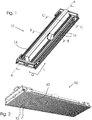
- FIG. Fig. 1 An embodiment of a ceiling air conditioning device 10 is shown in FIG Fig. 1, Fig.2 shown in perspective. How especially out Fig. 2 can be seen, a plurality of parallel ribs 12 are arranged on the underside. On the top are like in Fig. 1 an air duct 14 and line sections 16 of a cooling line are shown.
- the air duct 14 extends in a longitudinal direction L, while the ribs 12 run at right angles in a transverse direction Q.
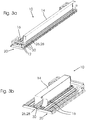
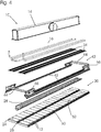
- the structure of the ceiling air conditioning device 10 is particularly from the cut perspective views 3a, 3b as well as from the exploded view Fig. 4 evident.
- the ribs 12 are formed on a profile element 20.
- the profile element 20 is composed of a plurality of partial profile elements 22, one of which is shown in FIG Fig. 6 is shown.
- the partial profile elements 22 are placed close together in the longitudinal direction L in order to form the profile element 20.
- Each of the partial profile elements 22 is formed as a one-piece, solid element made of metal, for example aluminum, and can be produced in particular by the extrusion process. It points like in Fig. 6 shown a base plate 24 with a flat, closed top 24 from which the ribs 12 extend. An opening 26 in the base plate 24 runs centrally in the longitudinal direction L.
- a distribution plate 28 is arranged in the opening 26 and has a row of outlet openings 30 on both sides in the longitudinal direction L.
- the distribution plate 28 forms the underside of the air duct 14.
- the outlet openings 30 are each arranged between the ribs 12, so that air supplied from the air duct 14 is discharged through the outlet openings 30 in the spaces between the ribs 12.
- the outlet openings 30 are arranged such that the air flows essentially horizontally into the spaces between the ribs 12. As a result, ambient air is drawn in and there is an intensive heat transfer between the air flow and the ribs 12 of the profile element 20.
- the profile element 20 is cooled by the cooling line 16.
- the cooling line 16 runs in parallel line sections in the longitudinal direction L meandering on the top 24 of the profile element 20.
- Fixing profiles 34 are provided for this ( 7a, 7b ) with a holding area 36 which partially encompasses the line 16 and a support surface 38 for support on the upper side 24 of the profile element 20 ( 9, 10 ).
- the ceiling air conditioning device 10 comprises a support frame 42 ( Fig. 4 ) with two support profiles 40 which extend over the entire length of the ceiling air conditioning device 10 and which are connected at the end to cross struts 44.
- the support frame 42 and in particular the support profiles 40 serve on the one hand to connect the individual partial profile elements 22 to the overall profile element 20 and on the other hand to connect the ceiling air conditioning device 10 to other parts, in particular for suspending the ceiling air conditioning device.
- Sections of the support profiles 40 are in 8a, 8b shown, where Fig. 8b shows the cross section.
- each of the support profiles 40 has a first profile section 46a and a second profile section 46b, which are arranged at an angle of approximately 60 ° to one another.
- the support profiles 40 are provided for arrangement along the upper longitudinal edges 52 on both sides of the profile element 20.
- the first profile section 46a rests on the upper side 24 of the profile element 20, while the second profile section 46b rests on a side surface 54 that is bevelled against it.
- the profile element 20 has in its side surface 54 a groove 50, the depression of which extends in the horizontal direction starting from the side surface 54.
- the groove 50 is arranged on the side surface 54 of the profile element 20 in the region of the ribs 12, just below the base plate 24 forming the upper side.
- a spring 60 of the support profile 40 can be seen.
- the tongue 60 is received in the groove 50 such that there is a contact surface over the entire length L on the top of the groove 50 and tongue 60.
- the support profile 40 can the weight of the solid profile element 20 well take up.
- the spring 60 is as in Fig. 8b shown formed on the inside of the second profile section 46b.
- the second profile section 46b also has on its opposite outer side a rail area 56 with hold-down devices 58a, 58b arranged opposite on both sides.
- a notch 62 is provided on the outside of the first profile section 46a.
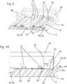
- the notch 62 is used to simply fix the support profile 40 to the profile element 20 by means of self-tapping screws 62 ( 9, 10 ). When assembled, the notch 62 is used for easy positioning of the screws 64 which are screwed through the first profile section 46a into the base plate 24 of the profile element 20. The screws 64 are anchored in the base plate 24 of the profile element 20 and do not penetrate them, ie do not protrude into the region of the ribs 12.
- the attachment of the support profile 40 to the profile element 20 takes place without the need to work in the space between the ribs 12; in addition, the attachment is not visible from the bottom.
- the support profile 40 also serves to fasten the holding plates 34 for the line sections 16 on the top of the profile element 20.
- a recess 64 is provided on the inside of the first profile section 46a of the support profile 20. How from Fig. 10 it can be seen, the first profile section 46a covers the edge of the holding plate 34 running next to it at this point and thus fixes this on the upper side of the profile element 20.
- the rail area 56 on the outside of the second profile area 46b serves for the positive reception of connecting elements 66 ( 9, 10 ) and / or suspension elements 70 ( 11, 12 ).
- the connecting elements 66 serve as in FIG Fig. 10 shown for connecting the support profiles 40 to the cross struts 44.
- a foot region 68 of the connecting elements 66 is received in a form-fitting manner in the rail region 56 and additionally fixed by screws.
- suspension elements 70 can be fastened to the rail area 56, in which case, as in FIG Fig. 12 each shown, a foot area 74 is positively received in the rail area 56.
- the suspension elements 70 are used to suspend the ceiling air conditioning device 10.
- they are designed as angled sheets, an upper angled region 76 having a bore for receiving a threaded rod 72.
- a single ceiling air conditioning device 10 as well as a composite of several ceiling air conditioning devices can be securely suspended.
- the required number of suspension elements 70 is inserted into the rail area 56 of the support profiles 40. It has been found that four suspension points are sufficient for each ceiling air conditioning device 10.
- a plurality of ceiling air conditioning devices 10a, 10b can also be arranged one behind the other in the longitudinal direction.
- the support profiles 40 can run continuously or can be connected to one another at the ends.
Landscapes
- Engineering & Computer Science (AREA)
- General Engineering & Computer Science (AREA)
- Chemical & Material Sciences (AREA)
- Combustion & Propulsion (AREA)
- Mechanical Engineering (AREA)
- Architecture (AREA)
- Sustainable Development (AREA)
- Life Sciences & Earth Sciences (AREA)
- Physics & Mathematics (AREA)
- Electromagnetism (AREA)
- Civil Engineering (AREA)
- Structural Engineering (AREA)
- Duct Arrangements (AREA)
Description
- Die Erfindung betrifft eine Decken-Klimatisierungsvorrichtung.
- Ein bekannter Typ von Klimatisierungsvorrichtungen zur Anordnung an und insbesondere in einer Raumdecke umfasst sowohl eine Zuführung für Luft als auch für Wasser als zusätzliches Temperiermedium. Zur Zuführung von Luft verläuft ein Luftkanal in einer Längsrichtung der bekannten Anordnung. Unterhalb des Luftkanals ist ein Profilelement mit in Querrichtung verlaufenden Rippen angeordnet, das durch am Profilelement angeordnete Leitungen für Wasser als Temperiermedium zum Temperieren des Profilelements temperiert wird. Der Luftkanal weist eine Anzahl von zwischen den Rippen angeordneten Auslassöffnungen auf, durch die die Luft aus dem Luftkanal ausgeblasen wird.
Eine Klimatisierungsvorrichtung gemäß dem Oberbegriff von Anspruch 1 ist aus dem PatentdokumentCH-A-707246 - Es kann als Aufgabe angesehen werden, bei einer Decken-Klimatisierungsvorrichtung mit Luftkanal und Profilelement eine Möglichkeit zur einfachen Befestigung vorzusehen. Die Aufgabe wird gelöst durch eine Decken-Klimatisierungsvorrichtung gemäß Anspruch 1. Abhängige Ansprüche beziehen sich auf vorteilhafte Ausführungsformen der Erfindung. Die erfindungsgemäße Decken-Klimatisierungsvorrichtung weist mindestens einen in einer Längsrichtung verlaufenden Luftkanal zum Zuführen von Luft auf. Unterhalb des Luftkanals ist ein Profilelement mit einer Anzahl von in Querrichtung verlaufenden Rippen angeordnet. Das Profilelement besteht bevorzugt aus gut wärmeleitfähigem Material, insbesondere Metall, besonders bevorzugt Aluminium.
- Am Profilelement ist mindestens eine Leitung für ein Temperiermedium vorgesehen, durch das das Profilelement gekühlt oder geheizt werden kann. Als Temperiermedium wird bevorzugt Wasser genutzt. Für eine gute thermische Kopplung der Leitung mit dem Profilelement weist die Leitung bevorzugt mehrere verbundene Leitungsabschnitte auf, die insbesondere bevorzugt parallel, bspw. in Längsrichtung verlaufen können.
- Der Luftkanal weist eine Anzahl von zwischen den Rippen des Profilelements angeordneten Auslassöffnungen auf, so dass Luft durch die Auslassöffnungen in die Zwischenräume zwischen den Rippen ausgeblasen werden kann. Dabei sind die Auslassöffnungen bevorzugt so gestaltet, dass die Luft aus dem Luftkanal mindestens im Wesentlichen in Querrichtung, also längs der Rippen strömt. Die ausgeblasene Luft sowie ggf. durch den Luftstrom angesaugte Raumluft wird somit durch intensiven Kontakt mit dem Profilelement temperiert, d.h. üblicherweise gekühlt.
- Erfindungsgemäß ist mindestens ein Tragprofil an der Decken-Klimatisierungsvorrichtung vorgesehen. Zur Kopplung mit dem Tragprofil weist das Profilelement mindestens eine in Längsrichtung verlaufende Nut auf. Das Tragprofil verfügt über mindestens eine Feder zum Eingriff in die Nut. Dabei erstreckt sich das Tragprofil und somit bevorzugt sowohl Nut als auch Feder in Längsrichtung.
- Das Tragprofil bietet somit eine günstige Möglichkeit einerseits zur Stabilisierung des Profilelements sowie andererseits zur Verbindung des Profilelements mit anderen Teilen der Vorrichtung. Vor allem aber kann das Tragprofil zur Aufhängung der gesamten Decken-Klimatisierungsvorrichtung dienen.
- Bevorzugt erstreckt sich das Tragprofil zumindest im Wesentlichen über die Länge des Profilelements, worunter vorliegend eine Länge von mindestens 80%, bevorzugt 90% der Länge, besonders bevorzugt die gesamte Länge verstanden wird. Das Tragprofil ist bevorzugt einstückig gebildet, insbesondere bevorzugt aus Metall. Bevorzugt hat das Tragprofil durchgehend gleichbleibenden Querschnitt, d. h. insbesondere die Feder ist bevorzugt über seine gesamte Länge ausgebildet.
- Nut und Feder weisen ineinander passende Formen auf, so dass eine formschlüssige Aufnahme gebildet wird.
- Während die Nut an verschiedenen Stellen des Profilelements, bspw. auch an dessen Ober- oder Unterseite gebildet sein könnte, ist sie bevorzugt an mindestens einer der Längsseiten angeordnet; besonders bevorzugt weisen die beiden gegenüberliegenden Längsseiten jeweils Nuten auf. Die Vertiefung jeder Nut erstreckt sich bevorzugt mindestens im Wesentlichen in horizontaler Richtung, so dass durch den Eingriff zwischen Nut und Feder die Traglast in vertikaler Richtung aufgenommen werden kann.
- Gemäß einer bevorzugten Ausführungsform weist das Tragprofil im Querschnitt mindestens einen ersten Profilabschnitt auf, der auf der Oberseite des Profilelements aufliegt und einen zweiten Profilabschnitt, der an einer Seitenfläche des Profilelements aufliegt. Das Tragprofil übergreift somit bevorzugt eine Längskante, besonders bevorzugt die obere Längskante des Profilelements. Dabei ist die Feder bevorzugt am zweiten Profilabschnitt angeordnet, der auf der Seitenfläche aufliegt, wo sich gemäß der bevorzugten Ausführungsform die zugehörige Nut befindet. Der erste Profilabschnitt kann hingegen auf der Oberseite des Profilelements auf verschiedene Weise befestigt sein. In einer bevorzugten Ausführungsform ist der erste Profilabschnitt auf der Oberseite des Profilelements durch mindestens eine Schraube, bevorzugt durch mehrere in Längsrichtung beabstandete Schrauben befestigt.
- Bei der Befestigung des Tragprofils am Profilelement durch Schrauben ist es besonders bevorzugt, dass die Schrauben durch das Tragprofil hindurch greifen und an der Oberseite des Profilelements ohne Durchgang zur Unterseite verankert sind. Dies kann bspw. durch selbst schneidende Schrauben erreicht werden oder durch ein zuvor eingebrachtes Gewinde an der Oberseite des Profilelements. Eine Verschraubung nur an der Oberseite ohne Durchgang zur Unterseite des Profilelements bietet einerseits den Vorteil, dass die Befestigung von der Unterseite, d. h. an der Raumdecke nicht sichtbar ist. Andererseits werden auch bei der Anbringung jegliche Arbeiten an der Unterseite, insbesondere zwischen den Rippen, vermieden, die ggf. zu sichtbaren Kratzern, Verbiegungen oder sonstigen Beschädigungen führen könnten.
- Das Profilelement kann im Querschnitt verschiedenste Formen aufweisen. Bevorzugt sind Ober- und Unterseite plan und parallel. Die längs verlaufenden Seitenflächen können ganz oder zum Teil senkrecht zur Oberseite verlaufen. In einer bevorzugten Ausführungsform kann jedoch mindestens ein Abschnitt einer Seitenfläche des Profilelements mit der Oberseite einen Winkel von weniger als 90° bilden, d. h. schräg nach außen verlaufen. Der Winkel kann bspw. 45° oder größer sein, bevorzugt bspw. 50° bis 70°.
- Am Profilelement, bevorzugt an dessen Oberseite, kann mindestens eine Halterung für die Leitung angeordnet sein. Die Halterung kann einen Leitungserfassungsbereich aufweisen, der eine bspw. runde Leitung mindestens teilweise umgreift sowie einen bspw. flachen Kontaktbereich zur Anlage an der Oberseite des Profilelements. Die Halterung kann, zumindest zum Teil, durch das Tragprofil am Profilelement befestigt sein. Bspw. kann ein Teil der Halterung, bevorzugt der flache Kontaktbereich, zwischen dem Tragprofil und dem Profilelement eingeklemmt und so befestigt sein. So kann auf einfache Weise eine gute Befestigung und Anlage erreicht werden.
- In einer bevorzugten Ausführungsform kann das Tragprofil einen Schienenbereich aufweisen, in dem ein Aufhängeelement oder ein Verbindungselement formschlüssig aufgenommen werden kann. Bevorzugt weist ein solcher Schienenbereich an gegenüberliegenden Längsseiten jeweils eine Hinterschneidung auf, so dass ein formschlüssig darin aufgenommenes Element an gegenüberliegenden Seiten umgriffen wird. Der Schienenbereich und das dazu passende Aufhängeelement oder Verbindungselement sind somit bevorzugt so geformt, dass mindestens ein Teil, bspw. ein Fuß, in Längsrichtung in den Schienenbereich eingeschoben werden kann. Das Aufhängeelement kann insbesondere zum Aufhängen des Profilelements bzw. der gesamten Decken-Klimatisierungsvorrichtung im Deckenbereich dienen. Hierzu kann das Aufhängeelement eine mindestens im Wesentlichen senkrecht angeordnete Gewindestange aufweisen, mit der eine Aufhängung in einstellbarer Höhe erreicht werden kann. Es können für eine Decken-Klimatisierungsvorrichtung bspw. vier Aufhängeelemente vorgesehen sein.
- Besonders bevorzugt können zwei Tragprofile parallel im Abstand voneinander vorgesehen sein. Dabei ist es möglich, die Tragprofile durch mindestens eine Querstrebe, bevorzugt durch mindestens zwei im Abstand voneinander angeordnete Querstreben zu einem Rahmen zu verbinden. Mit einem derartigen Rahmen kann eine besonders hohe Stabilität der gesamten Decken-Klimatisierungsvorrichtung erzielt werden.
- Das Profilelement kann es einstückig oder zumindest abschnittsweise einstückig gebildet sein. Bevorzugt kann aus mehreren Teilprofilelementen zusammengesetzt sein, wobei jedes der Teilprofilelemente bevorzugt einstückig mit einer Mehrzahl von Rippen ausgebildet ist.
- Mehrere Teilprofilelemente können bspw. in Längsrichtung nebeneinander vorgesehen sein. Eine Verbindung der Teilprofilelemente kann insbesondere durch das Tragprofil erreicht werden.
- Nachfolgend wird eine Ausführungsform der Erfindung anhand von Zeichnungen näher beschrieben. Dabei zeigen:
- Fig. 1
- in perspektivischer Ansicht von oben eine Ausführungsform einer Decken-Klimatisierungsvorrichtung;
- Fig. 2
- die Decken-Klimatisierungsvorrichtung aus
Fig. 1 in einer perspektivischen Ansicht von unten; - Fig. 3a
- in perspektivischer Ansicht die Decken-Klimatisierungsvorrichtung aus
Fig. 1, Fig. 2 geschnitten entlang der Linie A...A inFig. 1 ; - Fig. 3b
- in perspektivischer Ansicht die Decken-Klimatisierungsvorrichtung aus
Fig. 1, Fig. 2 geschnitten entlang der Linie B...B inFig. 1 ; - Fig. 4
- eine perspektivische Explosionsdarstellung der Decken-Klimatisierungsvorrichtung aus
Fig. 1, Fig. 2 ; - Fig. 5a, 5b
- perspektivische Darstellung und Seitenansicht eines Verteilblechs als Teil der Decken-Klimatisierungsvorrichtung;
- Fig. 6
- in perspektivischer Darstellung ein Teilprofilelement der Decken-Klimatisierungsvorrichtung;
- Fig. 7a, 7b
- in perspektivischer Darstellung und in Frontansicht ein Halteelement für eine Leitung als Teil der Decken-Klimatisierungsvorrichtung;
- Fig. 8a, 8b
- in perspektivischer Darstellung sowie in Frontansicht ein Tragprofil als Teil der Decken-Klimatisierungsvorrichtung;
- Fig. 9
- in perspektivischer Darstellung die Decken-Klimatisierungsvorrichtung geschnitten entlang der Linie C..C in
Fig. 1 ; - Fig. 10
- teilweise Darstellung eines Schnitts entlang der Linie C..C in
Fig. 1 ; - Fig. 11
- in perspektivischer Darstellung zwei Decken-Klimatisierungsvorrichtungen mit Aufhängung;
- Fig. 12
- in einer Querschnittsdarstellung eine Aufhängevorrichtung der Decken-Klimatisierungsvorrichtung aus
Fig. 11 . - Eine Ausführungsform einer Decken-Klimatisierungsvorrichtung 10 ist in
Fig. 1, Fig.2 in perspektivischen Darstellungen gezeigt. Wie insbesondere ausFig. 2 ersichtlich ist, sind an der Unterseite eine Vielzahl von parallelen Rippen 12 angeordnet. Auf der Oberseite sind wie inFig. 1 dargestellt ein Luftkanal 14 sowie Leitungsabschnitte 16 einer Kühlleitung angeordnet. Der Luftkanal 14 erstreckt sich in einer Längsrichtung L, während die Rippen 12 hierzu rechtwinklig in einer Querrichtung Q verlaufen. - Der Aufbau der Decken-Klimatisierungsvorrichtung 10 ist insbesondere aus den geschnittenen perspektivischen Darstellungen
Fig. 3a, 3b sowie aus der ExplosionsdarstellungFig. 4 ersichtlich. Die Rippen 12 sind gebildet an einem Profilelement 20. Das Profilelement 20 ist zusammengesetzt aus einer Mehrzahl von Teil-Profilelementen 22, von denen eines beispielhaft inFig. 6 dargestellt ist. Die Teil-Profilelemente 22 sind in Längsrichtung L dicht aneinandergesetzt, um so zusammengefasst das Profilelement 20 zu bilden. - Jedes der Teil-Profilelemente 22 ist als einstückiges, massives Element aus Metall, bspw. Aluminium gebildet und kann insbesondere im Strangpressverfahren hergestellt sein. Es weist wie in
Fig. 6 dargestellt eine Grundplatte 24 auf mit einer flachen, geschlossenen Oberseite 24, von der sich die Rippen 12 erstrecken. Mittig verläuft in Längsrichtung L eine Durchbrechung 26 der Grundplatte 24. - In der Durchbrechung 26 ist ein Verteilblech 28 angeordnet, das zu beiden Seiten in Längsrichtung L eine Reihe von Auslassöffnungen 30 aufweist. Das Verteilblech 28 bildet die Unterseite des Luftkanals 14.
- Die Auslassöffnungen 30 sind jeweils zwischen den Rippen 12 angeordnet, so dass zugeführte Luft aus dem Luftkanal 14 durch die Auslassöffnungen 30 in den Zwischenräumen zwischen den Rippen 12 abgegeben wird. Dabei sind die Auslassöffnungen 30 so angeordnet, dass die Luft im Wesentlichen horizontal in die Zwischenräume zwischen den Rippen 12 strömt. Hierdurch wird Raumluft angesaugt und es erfolgt ein intensiver Wärmeübergang zwischen dem Luftstrom und den Rippen 12 des Profilelements 20.
- Dabei wird das Profilelement 20 durch die Kühlleitung 16 gekühlt. Die Kühlleitung 16 verläuft in parallelen Leitungsabschnitten in Längsrichtung L mäanderförmig auf der Oberseite 24 des Profilelements 20. Hierfür sind Befestigungsprofile 34 vorgesehen (
Fig. 7a, 7b ) mit einem Haltebereich 36, der die Leitung 16 teilweise umfasst und einer Auflagefläche 38 zur Auflage auf der Oberseite 24 des Profilelements 20 (Fig. 9, 10 ). - Die Decken-Klimatisierungsvorrichtung 10 umfasst einen Tragrahmen 42 (
Fig. 4 ) mit zwei Tragprofilen 40, die sich über die gesamte Länge der Decken-Klimatisierungsvorrichtung 10 erstrecken und die endseitig mit Querstreben 44 verbunden sind. Der Tragrahmen 42 und insbesondere die Tragprofile 40 dienen einerseits zur Verbindung der einzelnen Teil-Profilelemente 22 zum Gesamt-Profilelement 20 und andererseits zur Verbindung der Decken-Klimatisierungsvorrichtung 10 mit anderen Teilen, insbesondere zur Aufhängung der Decken-Klimatisierungsvorrichtung. - Abschnitte der Tragprofile 40 sind in
Fig. 8a, 8b dargestellt, wobeiFig. 8b den Querschnitt zeigt. Jedes der Tragprofile 40 verfügt im Querschnitt über einen ersten Profilabschnitt 46a und einen zweiten Profilabschnitt 46b, die zueinander unter einem Winkel von etwa 60° angeordnet sind. - Wie insbesondere aus
Fig. 9, Fig. 10 ,Fig. 12 ersichtlich ist, sind die Tragprofile 40 zur Anordnung entlang der oberen Längskanten 52 auf beiden Seiten des Profilelements 20 vorgesehen. Dabei liegt der erste Profilabschnitt 46a auf der Oberseite 24 des Profilelements 20 auf, während der zweite Profilabschnitt 46b auf einer hiergegen abgeschrägten Seitenfläche 54 aufliegt. - Um eine tragende Verbindung zwischen dem Tragprofil 40 und dem Profilelement 20 zu ermöglichen, weist das Profilelement 20 in seiner Seitenfläche 54 eine Nut 50 auf, deren Vertiefung sich ausgehend von der Seitenfläche 54 in horizontaler Richtung erstreckt. Im dargestellten Beispiel ist die Nut 50 an der Seitenfläche 54 des Profilelements 20 im Bereich der Rippen 12 angeordnet, knapp unterhalb der die Oberseite bildenden Grundplatte 24.
- In die Nut 50 greift wie insbesondere aus
Fig. 9, Fig. 10 ,Fig. 12 ersichtlich ist eine Feder 60 des Tragprofils 40 ein. Die Feder 60 ist in der Nut 50 so aufgenommen, dass sich an der Oberseite von Nut 50 und Feder 60 eine Anlagefläche über die gesamte Länge L ergibt. So kann das Tragprofil 40 die Gewichtskraft des massiv ausgebildeten Profilelements 20 gut aufnehmen. - Die Feder 60 ist wie in
Fig. 8b dargestellt auf der Innenseite des zweiten Profilabschnitts 46b gebildet. Der zweite Profilabschnitt 46b weist auf seiner gegenüberliegenden Außenseite zudem einen Schienenbereich 56 mit auf beiden Seiten gegenüberliegend angeordneten Niederhaltern 58a, 58b auf. Auf der Außenseite des ersten Profilabschnitts 46a ist eine Kerbe 62 vorgesehen. - Die Kerbe 62 dient zum einfachen Fixieren des Tragprofils 40 am Profilelement 20 mittels selbstschneidender Schrauben 62 (
Fig. 9, 10 ). Beim Zusammenbau dient die Kerbe 62 zum einfachen Positionieren der Schrauben 64, die durch den ersten Profilabschnitt 46a hindurch in die Grundplatte 24 des Profilelements 20 eingeschraubt werden. Dabei sind die Schrauben 64 in der Grundplatte 24 des Profilelements 20 verankert und durchdringen diese nicht, d. h. ragen nicht bis in den Bereich der Rippen 12. - Somit erfolgt die Befestigung des Tragprofils 40 am Profilelement 20, ohne dass Arbeiten im Zwischenraum zwischen den Rippen 12 erforderlich sind; zudem ist die Befestigung von der Unterseite nicht sichtbar.
- Das Tragprofil 40 dient zusätzlich auch zur Befestigung der Haltebleche 34 für die Leitungsabschnitte 16 auf der Oberseite des Profilelements 20. Hierzu ist auf der Innenseite des ersten Profilabschnitts 46a des Tragprofils 20 eine Aussparung 64 vorgesehen. Wie aus
Fig. 10 ersichtlich ist, überdeckt der erste Profilabschnitt 46a an dieser Stelle die Kante des daneben verlaufenden Halteblechs 34 und fixiert dieses somit auf der Oberseite des Profilelements 20. - Der Schienenbereich 56 auf der Außenseite des zweiten Profilbereichs 46b dient zur formschlüssigen Aufnahme von Verbindungselementen 66 (
Fig. 9, 10 ) und/oder Aufhängeelementen 70 (Fig. 11, 12 ). - Die Verbindungselemente 66 dienen wie in
Fig. 10 gezeigt zur Verbindung der Tragprofile 40 mit den Querstreben 44. Ein Fußbereich 68 der Verbindungselemente 66 ist formschlüssig im Schienenbereich 56 aufgenommen und zusätzlich durch Schrauben fixiert. - Zusätzlich oder alternativ können am Schienenbereich 56 Aufhängeelemente 70 befestigt sein, bei denen wie in
Fig. 12 dargestellt jeweils ein Fußbereich 74 formschlüssig im Schienenbereich 56 aufgenommen ist. - Die Aufhängeelemente 70 dienen zur Aufhängung der Decken-Klimatisierungsvorrichtung 10. Im gezeigten Beispiel sind sie als Winkelbleche ausgebildet, wobei ein oberer abgewinkelter Bereich 76 eine Bohrung zur Aufnahme einer Gewindestange 72 aufweist.
- Auf diese Weise kann eine einzelne Decken-Klimatisierungsvorrichtung 10 ebenso wie ein Verbund aus mehreren Decken-Klimatisierungsvorrichtungen sicher aufgehängt werden. Hierfür wird die benötigte Anzahl an Aufhängeelementen 70 in den Schienenbereich 56 der Tragprofile 40 eingeschoben. Dabei hat sich erwiesen, dass vier Aufhängepunkte für jede Decken-Klimatisierungsvorrichtung 10 ausreichend sind.
- Wie in
Fig. 11 dargestellt können auch mehrere Decken-Klimatisierungsvorrichtungen 10a, 10b in Längsrichtung hintereinander angeordnet werden. Dabei können die Tragprofile 40 durchgängig verlaufen oder jeweils endseitig miteinander verbunden werden.
Claims (13)
- Decken-Klimatisierungsvorrichtung, mit- mindestens einem in einer Längsrichtung (L) verlaufenden Luftkanal (14) zum Zuführen von Luft- mindestens einem unterhalb des Luftkanals (14) angeordneten Profilelement (20) mit einer Anzahl von in Querrichtung (Q) verlaufenden Rippen (12),- und mindestens einer am Profilelement (20) angeordneten Leitung (16) für ein Temperiermedium zum Temperieren des Profilelements (20),- wobei der Luftkanal (14) eine Anzahl von zwischen den Rippen (12) angeordneten Auslassöffnungen (30) aufweist,
dadurch gekennzeichnet, dass- das Profilelement (20) mindestens eine in Längsrichtung verlaufende Nut (50) aufweist,- und mindestens ein in Längsrichtung (L) verlaufendes Tragprofil (40) vorgesehen ist, das mindestens eine Feder (60) zum Eingriff in die Nut (50) aufweist. - Decken-Klimatisierungsvorrichtung nach Anspruch 1, bei der- das Tragprofil (40) einen ersten Profilabschnitt (46a) aufweist, der auf der Oberseite des Profilelements (20) aufliegt und einen zweiten Profilabschnitt (46b), der an einer Seitenfläche (54) des Profilelements (20) aufliegt.
- Decken-Klimatisierungsvorrichtung nach Anspruch 2, bei der- die Feder (60) am zweiten Profilabschnitt (46b) angeordnet ist.
- Decken-Klimatisierungsvorrichtung nach Anspruch 2 oder 3, bei der- der erste Profilabschnitt (46a) auf der Oberseite des Profilelements (20) durch mindestens eine Schraube (64) befestigt ist.
- Decken-Klimatisierungsvorrichtung nach Anspruch 4, bei der- die Schraube (64) durch das Tragprofil (40) hindurchgreift und in der Oberseite (24) des Profilelements (20) ohne Durchgang zur Unterseite verankert ist.
- Decken-Klimatisierungsvorrichtung nach Anspruch 4 oder 5, bei der- am ersten Profilabschnitt (46a) mindestens eine Kerbe (62) vorgesehen ist,- und die Schraube (64) in der Kerbe (62) durch das Tragprofil (40) geschraubt ist.
- Decken-Klimatisierungsvorrichtung nach einem der vorangehenden Ansprüche, bei der- eine Seitenfläche (54) des Profilelements (20) mit der Oberseite des Profilelements (20) einen Winkel von weniger als 90° aufweist.
- Decken-Klimatisierungsvorrichtung nach einem der vorangehenden Ansprüche, bei der- am Profilelement (20) mindestens eine Halterung (34) für die Leitung (16) vorgesehen ist,- wobei die Halterung (34) durch das Tragprofil (40) am Profilelement (20) befestigt ist.
- Decken-Klimatisierungsvorrichtung nach einem der vorangehenden Ansprüche, bei der- ein Schienenbereich (56) des Tragprofils (40) an gegenüberliegenden Seiten jeweils eine Hinterschneidung (58a, 58b) aufweist,- und ein Aufhängelement (70) und/oder ein Verbindungselement (66) mindestens zum Teil formschlüssig im Schienenbereich (56) aufgenommen ist.
- Decken-Klimatisierungsvorrichtung nach Anspruch 9, bei der- das Aufhängeelement (70) einen Aufnahmebereich für eine Gewindestange (72) aufweist.
- Decken-Klimatisierungsvorrichtung nach Anspruch 9 oder 10, bei der- vier Aufhängeelemente (70) an der Decken-Klimatisierungsvorrichtung vorgesehen sind.
- Decken-Klimatisierungsvorrichtung nach einem der vorangehenden Ansprüche, bei der- mindestens zwei Tragprofile (40) im Abstand zueinander angeordnet und durch mindestens eine Querstrebe (44) zu einem Rahmen (42) verbunden sind.
- Decken-Klimatisierungsvorrichtung nach einem der vorangehenden Ansprüche, bei der- das Profilelement (20) mehrere Teil-Profilelemente (22) umfasst, die durch das Tragprofil (40) aneinander befestigt sind.
Applications Claiming Priority (1)
| Application Number | Priority Date | Filing Date | Title |
|---|---|---|---|
| DE202017103113.6U DE202017103113U1 (de) | 2017-05-23 | 2017-05-23 | Decken-Klimatisierungsvorrichtung mit Tragkonstruktion |
Publications (2)
| Publication Number | Publication Date |
|---|---|
| EP3406975A1 EP3406975A1 (de) | 2018-11-28 |
| EP3406975B1 true EP3406975B1 (de) | 2020-03-25 |
Family
ID=59650713
Family Applications (1)
| Application Number | Title | Priority Date | Filing Date |
|---|---|---|---|
| EP18171325.6A Active EP3406975B1 (de) | 2017-05-23 | 2018-05-08 | Decken-klimatisierungsvorrichtung mit tragkonstruktion |
Country Status (2)
| Country | Link |
|---|---|
| EP (1) | EP3406975B1 (de) |
| DE (1) | DE202017103113U1 (de) |
Family Cites Families (6)
| Publication number | Priority date | Publication date | Assignee | Title |
|---|---|---|---|---|
| NL1004187C2 (nl) * | 1996-10-03 | 1998-04-06 | Luchttechnisch Adviesbureau Ev | Convector. |
| DE102004018278B4 (de) * | 2004-04-13 | 2006-01-19 | Thermosoft Klimatechnik Gmbh | Decke, insbesondere Kühl-oder Heizdecke |
| JP2007127292A (ja) * | 2005-11-01 | 2007-05-24 | Showa Denko Kk | 輻射冷暖房ユニット |
| AU2010201383B9 (en) * | 2009-04-13 | 2011-06-02 | Kimura Kohki Co., Ltd. | Heating and cooling unit, and heating and cooling apparatus |
| CH707246A1 (de) * | 2012-11-29 | 2014-05-30 | Barcol Air | Deckenelement für eine Heiz- und Kühldecke sowie Heiz- und Kühldecke. |
| SE537916C2 (sv) * | 2014-04-08 | 2015-11-24 | Fläkt Woods AB | Anordning och förfarande för reglering av ett tilluftsflödevid ett luftbehandlingssystem |
-
2017
- 2017-05-23 DE DE202017103113.6U patent/DE202017103113U1/de not_active Expired - Lifetime
-
2018
- 2018-05-08 EP EP18171325.6A patent/EP3406975B1/de active Active
Non-Patent Citations (1)
| Title |
|---|
| None * |
Also Published As
| Publication number | Publication date |
|---|---|
| DE202017103113U1 (de) | 2017-07-31 |
| EP3406975A1 (de) | 2018-11-28 |
Similar Documents
| Publication | Publication Date | Title |
|---|---|---|
| EP0849541B1 (de) | Deckenelement für eine Heiz- und Kühldecke | |
| DE102010022415B4 (de) | Montagelasche für abgehängte Decken | |
| DE102018114621A1 (de) | Trägersystem zur Anordnung einer Photovoltaikeinheit aufweisend mindestens ein Photovoltaikmodul | |
| EP4113013A1 (de) | Verkleidungssystem mit einer heiz- und/oder kühleinrichtung | |
| EP4113014B1 (de) | Verkleidungssystem mit einer heiz- und/oder kühleinrichtung | |
| EP0733865B1 (de) | Konstruktion einer Heiz- und/oder Kühldecke | |
| EP3775702B1 (de) | Deckenstrahlplatten-anordnung | |
| DE8401528U1 (de) | Infrarotstrahlvorrichtung | |
| EP3406975A1 (de) | Decken-klimatisierungsvorrichtung mit tragkonstruktion | |
| AT527060A4 (de) | Halteschiene zur Befestigung an Trockenbauprofilen | |
| DE202004016002U1 (de) | Fassadenbefestigungssystem | |
| DE102014226713A1 (de) | Deckenradiatorprofil | |
| DE202022106450U1 (de) | Wärmestrahler | |
| DE102017102536A1 (de) | Halterung zur Befestigung einer Verkleidung an einer Gebäudewand oder -decke | |
| DE102016104405A1 (de) | Verfahren zur Montage einer Pfosten-Riegel-Konstruktion und Montagehilfe | |
| DE19500670C1 (de) | Kühlvorrichtung | |
| DE20014447U1 (de) | Plattenförmiges Wärmetauschelement | |
| DE3412631C2 (de) | Pflanzenkühlraum | |
| DE20300293U1 (de) | Fassade oder Lichtdach | |
| EP1406021A1 (de) | Befestigungsvorrichtung | |
| DE102016121953A1 (de) | Decken- und/oder Wandverkleidung und Herstellungsverfahren hierfür | |
| EP1606557A1 (de) | Strahlfl chenaufbau | |
| DE9114775U1 (de) | Wärmeaustauscher | |
| DE19835666C2 (de) | Temperierbares Rahmenelement | |
| DE3347227C2 (de) |
Legal Events
| Date | Code | Title | Description |
|---|---|---|---|
| PUAI | Public reference made under article 153(3) epc to a published international application that has entered the european phase |
Free format text: ORIGINAL CODE: 0009012 |
|
| STAA | Information on the status of an ep patent application or granted ep patent |
Free format text: STATUS: THE APPLICATION HAS BEEN PUBLISHED |
|
| AK | Designated contracting states |
Kind code of ref document: A1 Designated state(s): AL AT BE BG CH CY CZ DE DK EE ES FI FR GB GR HR HU IE IS IT LI LT LU LV MC MK MT NL NO PL PT RO RS SE SI SK SM TR |
|
| AX | Request for extension of the european patent |
Extension state: BA ME |
|
| STAA | Information on the status of an ep patent application or granted ep patent |
Free format text: STATUS: REQUEST FOR EXAMINATION WAS MADE |
|
| 17P | Request for examination filed |
Effective date: 20190325 |
|
| RBV | Designated contracting states (corrected) |
Designated state(s): AL AT BE BG CH CY CZ DE DK EE ES FI FR GB GR HR HU IE IS IT LI LT LU LV MC MK MT NL NO PL PT RO RS SE SI SK SM TR |
|
| RIC1 | Information provided on ipc code assigned before grant |
Ipc: F24F 13/072 20060101ALI20190710BHEP Ipc: F24F 1/0007 20190101ALI20190710BHEP Ipc: F24F 5/00 20060101ALI20190710BHEP Ipc: E04B 9/02 20060101ALI20190710BHEP Ipc: F24F 13/30 20060101ALI20190710BHEP Ipc: F24F 1/00 20190101AFI20190710BHEP |
|
| GRAP | Despatch of communication of intention to grant a patent |
Free format text: ORIGINAL CODE: EPIDOSNIGR1 |
|
| STAA | Information on the status of an ep patent application or granted ep patent |
Free format text: STATUS: GRANT OF PATENT IS INTENDED |
|
| INTG | Intention to grant announced |
Effective date: 20190821 |
|
| GRAS | Grant fee paid |
Free format text: ORIGINAL CODE: EPIDOSNIGR3 |
|
| GRAJ | Information related to disapproval of communication of intention to grant by the applicant or resumption of examination proceedings by the epo deleted |
Free format text: ORIGINAL CODE: EPIDOSDIGR1 |
|
| GRAL | Information related to payment of fee for publishing/printing deleted |
Free format text: ORIGINAL CODE: EPIDOSDIGR3 |
|
| STAA | Information on the status of an ep patent application or granted ep patent |
Free format text: STATUS: REQUEST FOR EXAMINATION WAS MADE |
|
| INTC | Intention to grant announced (deleted) | ||
| GRAR | Information related to intention to grant a patent recorded |
Free format text: ORIGINAL CODE: EPIDOSNIGR71 |
|
| STAA | Information on the status of an ep patent application or granted ep patent |
Free format text: STATUS: GRANT OF PATENT IS INTENDED |
|
| GRAA | (expected) grant |
Free format text: ORIGINAL CODE: 0009210 |
|
| STAA | Information on the status of an ep patent application or granted ep patent |
Free format text: STATUS: THE PATENT HAS BEEN GRANTED |
|
| INTG | Intention to grant announced |
Effective date: 20200213 |
|
| AK | Designated contracting states |
Kind code of ref document: B1 Designated state(s): AL AT BE BG CH CY CZ DE DK EE ES FI FR GB GR HR HU IE IS IT LI LT LU LV MC MK MT NL NO PL PT RO RS SE SI SK SM TR |
|
| REG | Reference to a national code |
Ref country code: GB Ref legal event code: FG4D Free format text: NOT ENGLISH |
|
| REG | Reference to a national code |
Ref country code: AT Ref legal event code: REF Ref document number: 1248989 Country of ref document: AT Kind code of ref document: T Effective date: 20200415 Ref country code: IE Ref legal event code: FG4D Free format text: LANGUAGE OF EP DOCUMENT: GERMAN |
|
| REG | Reference to a national code |
Ref country code: DE Ref legal event code: R096 Ref document number: 502018001009 Country of ref document: DE |
|
| PG25 | Lapsed in a contracting state [announced via postgrant information from national office to epo] |
Ref country code: RS Free format text: LAPSE BECAUSE OF FAILURE TO SUBMIT A TRANSLATION OF THE DESCRIPTION OR TO PAY THE FEE WITHIN THE PRESCRIBED TIME-LIMIT Effective date: 20200325 Ref country code: FI Free format text: LAPSE BECAUSE OF FAILURE TO SUBMIT A TRANSLATION OF THE DESCRIPTION OR TO PAY THE FEE WITHIN THE PRESCRIBED TIME-LIMIT Effective date: 20200325 Ref country code: NO Free format text: LAPSE BECAUSE OF FAILURE TO SUBMIT A TRANSLATION OF THE DESCRIPTION OR TO PAY THE FEE WITHIN THE PRESCRIBED TIME-LIMIT Effective date: 20200625 |
|
| PG25 | Lapsed in a contracting state [announced via postgrant information from national office to epo] |
Ref country code: GR Free format text: LAPSE BECAUSE OF FAILURE TO SUBMIT A TRANSLATION OF THE DESCRIPTION OR TO PAY THE FEE WITHIN THE PRESCRIBED TIME-LIMIT Effective date: 20200626 Ref country code: BG Free format text: LAPSE BECAUSE OF FAILURE TO SUBMIT A TRANSLATION OF THE DESCRIPTION OR TO PAY THE FEE WITHIN THE PRESCRIBED TIME-LIMIT Effective date: 20200625 Ref country code: SE Free format text: LAPSE BECAUSE OF FAILURE TO SUBMIT A TRANSLATION OF THE DESCRIPTION OR TO PAY THE FEE WITHIN THE PRESCRIBED TIME-LIMIT Effective date: 20200325 Ref country code: LV Free format text: LAPSE BECAUSE OF FAILURE TO SUBMIT A TRANSLATION OF THE DESCRIPTION OR TO PAY THE FEE WITHIN THE PRESCRIBED TIME-LIMIT Effective date: 20200325 Ref country code: HR Free format text: LAPSE BECAUSE OF FAILURE TO SUBMIT A TRANSLATION OF THE DESCRIPTION OR TO PAY THE FEE WITHIN THE PRESCRIBED TIME-LIMIT Effective date: 20200325 |
|
| REG | Reference to a national code |
Ref country code: NL Ref legal event code: MP Effective date: 20200325 |
|
| REG | Reference to a national code |
Ref country code: LT Ref legal event code: MG4D |
|
| PG25 | Lapsed in a contracting state [announced via postgrant information from national office to epo] |
Ref country code: NL Free format text: LAPSE BECAUSE OF FAILURE TO SUBMIT A TRANSLATION OF THE DESCRIPTION OR TO PAY THE FEE WITHIN THE PRESCRIBED TIME-LIMIT Effective date: 20200325 |
|
| PG25 | Lapsed in a contracting state [announced via postgrant information from national office to epo] |
Ref country code: SM Free format text: LAPSE BECAUSE OF FAILURE TO SUBMIT A TRANSLATION OF THE DESCRIPTION OR TO PAY THE FEE WITHIN THE PRESCRIBED TIME-LIMIT Effective date: 20200325 Ref country code: EE Free format text: LAPSE BECAUSE OF FAILURE TO SUBMIT A TRANSLATION OF THE DESCRIPTION OR TO PAY THE FEE WITHIN THE PRESCRIBED TIME-LIMIT Effective date: 20200325 Ref country code: IS Free format text: LAPSE BECAUSE OF FAILURE TO SUBMIT A TRANSLATION OF THE DESCRIPTION OR TO PAY THE FEE WITHIN THE PRESCRIBED TIME-LIMIT Effective date: 20200725 Ref country code: SK Free format text: LAPSE BECAUSE OF FAILURE TO SUBMIT A TRANSLATION OF THE DESCRIPTION OR TO PAY THE FEE WITHIN THE PRESCRIBED TIME-LIMIT Effective date: 20200325 Ref country code: RO Free format text: LAPSE BECAUSE OF FAILURE TO SUBMIT A TRANSLATION OF THE DESCRIPTION OR TO PAY THE FEE WITHIN THE PRESCRIBED TIME-LIMIT Effective date: 20200325 Ref country code: PT Free format text: LAPSE BECAUSE OF FAILURE TO SUBMIT A TRANSLATION OF THE DESCRIPTION OR TO PAY THE FEE WITHIN THE PRESCRIBED TIME-LIMIT Effective date: 20200818 Ref country code: CZ Free format text: LAPSE BECAUSE OF FAILURE TO SUBMIT A TRANSLATION OF THE DESCRIPTION OR TO PAY THE FEE WITHIN THE PRESCRIBED TIME-LIMIT Effective date: 20200325 Ref country code: LT Free format text: LAPSE BECAUSE OF FAILURE TO SUBMIT A TRANSLATION OF THE DESCRIPTION OR TO PAY THE FEE WITHIN THE PRESCRIBED TIME-LIMIT Effective date: 20200325 |
|
| REG | Reference to a national code |
Ref country code: DE Ref legal event code: R097 Ref document number: 502018001009 Country of ref document: DE |
|
| PG25 | Lapsed in a contracting state [announced via postgrant information from national office to epo] |
Ref country code: MC Free format text: LAPSE BECAUSE OF FAILURE TO SUBMIT A TRANSLATION OF THE DESCRIPTION OR TO PAY THE FEE WITHIN THE PRESCRIBED TIME-LIMIT Effective date: 20200325 Ref country code: IT Free format text: LAPSE BECAUSE OF FAILURE TO SUBMIT A TRANSLATION OF THE DESCRIPTION OR TO PAY THE FEE WITHIN THE PRESCRIBED TIME-LIMIT Effective date: 20200325 Ref country code: DK Free format text: LAPSE BECAUSE OF FAILURE TO SUBMIT A TRANSLATION OF THE DESCRIPTION OR TO PAY THE FEE WITHIN THE PRESCRIBED TIME-LIMIT Effective date: 20200325 Ref country code: ES Free format text: LAPSE BECAUSE OF FAILURE TO SUBMIT A TRANSLATION OF THE DESCRIPTION OR TO PAY THE FEE WITHIN THE PRESCRIBED TIME-LIMIT Effective date: 20200325 |
|
| PLBE | No opposition filed within time limit |
Free format text: ORIGINAL CODE: 0009261 |
|
| STAA | Information on the status of an ep patent application or granted ep patent |
Free format text: STATUS: NO OPPOSITION FILED WITHIN TIME LIMIT |
|
| PG25 | Lapsed in a contracting state [announced via postgrant information from national office to epo] |
Ref country code: PL Free format text: LAPSE BECAUSE OF FAILURE TO SUBMIT A TRANSLATION OF THE DESCRIPTION OR TO PAY THE FEE WITHIN THE PRESCRIBED TIME-LIMIT Effective date: 20200325 |
|
| 26N | No opposition filed |
Effective date: 20210112 |
|
| REG | Reference to a national code |
Ref country code: BE Ref legal event code: MM Effective date: 20200531 |
|
| PG25 | Lapsed in a contracting state [announced via postgrant information from national office to epo] |
Ref country code: FR Free format text: LAPSE BECAUSE OF NON-PAYMENT OF DUE FEES Effective date: 20200525 Ref country code: IE Free format text: LAPSE BECAUSE OF NON-PAYMENT OF DUE FEES Effective date: 20200508 |
|
| REG | Reference to a national code |
Ref country code: DE Ref legal event code: R082 Ref document number: 502018001009 Country of ref document: DE Representative=s name: MEISSNER BOLTE PATENTANWAELTE RECHTSANWAELTE P, DE Ref country code: DE Ref legal event code: R081 Ref document number: 502018001009 Country of ref document: DE Owner name: KAMPMANN GMBH & CO. KG, DE Free format text: FORMER OWNER: EMCO KLIMA GMBH, 49811 LINGEN, DE |
|
| PG25 | Lapsed in a contracting state [announced via postgrant information from national office to epo] |
Ref country code: SI Free format text: LAPSE BECAUSE OF FAILURE TO SUBMIT A TRANSLATION OF THE DESCRIPTION OR TO PAY THE FEE WITHIN THE PRESCRIBED TIME-LIMIT Effective date: 20200325 Ref country code: BE Free format text: LAPSE BECAUSE OF NON-PAYMENT OF DUE FEES Effective date: 20200531 |
|
| REG | Reference to a national code |
Ref country code: LU Ref legal event code: PD Owner name: KAMPMANN GMBH & CO. KG; DE Free format text: FORMER OWNER: EMCO KLIMA GMBH Effective date: 20210621 |
|
| REG | Reference to a national code |
Ref country code: AT Ref legal event code: PC Ref document number: 1248989 Country of ref document: AT Kind code of ref document: T Owner name: KAMPMANN GMBH & CO. KG, DE Effective date: 20210811 |
|
| REG | Reference to a national code |
Ref country code: CH Ref legal event code: PL |
|
| PG25 | Lapsed in a contracting state [announced via postgrant information from national office to epo] |
Ref country code: CH Free format text: LAPSE BECAUSE OF NON-PAYMENT OF DUE FEES Effective date: 20210531 Ref country code: LI Free format text: LAPSE BECAUSE OF NON-PAYMENT OF DUE FEES Effective date: 20210531 |
|
| PG25 | Lapsed in a contracting state [announced via postgrant information from national office to epo] |
Ref country code: TR Free format text: LAPSE BECAUSE OF FAILURE TO SUBMIT A TRANSLATION OF THE DESCRIPTION OR TO PAY THE FEE WITHIN THE PRESCRIBED TIME-LIMIT Effective date: 20200325 Ref country code: MT Free format text: LAPSE BECAUSE OF FAILURE TO SUBMIT A TRANSLATION OF THE DESCRIPTION OR TO PAY THE FEE WITHIN THE PRESCRIBED TIME-LIMIT Effective date: 20200325 Ref country code: CY Free format text: LAPSE BECAUSE OF FAILURE TO SUBMIT A TRANSLATION OF THE DESCRIPTION OR TO PAY THE FEE WITHIN THE PRESCRIBED TIME-LIMIT Effective date: 20200325 |
|
| PG25 | Lapsed in a contracting state [announced via postgrant information from national office to epo] |
Ref country code: MK Free format text: LAPSE BECAUSE OF FAILURE TO SUBMIT A TRANSLATION OF THE DESCRIPTION OR TO PAY THE FEE WITHIN THE PRESCRIBED TIME-LIMIT Effective date: 20200325 Ref country code: AL Free format text: LAPSE BECAUSE OF FAILURE TO SUBMIT A TRANSLATION OF THE DESCRIPTION OR TO PAY THE FEE WITHIN THE PRESCRIBED TIME-LIMIT Effective date: 20200325 |
|
| GBPC | Gb: european patent ceased through non-payment of renewal fee |
Effective date: 20220508 |
|
| PG25 | Lapsed in a contracting state [announced via postgrant information from national office to epo] |
Ref country code: GB Free format text: LAPSE BECAUSE OF NON-PAYMENT OF DUE FEES Effective date: 20220508 |
|
| P01 | Opt-out of the competence of the unified patent court (upc) registered |
Effective date: 20230529 |
|
| PGFP | Annual fee paid to national office [announced via postgrant information from national office to epo] |
Ref country code: LU Payment date: 20240426 Year of fee payment: 7 |
|
| PGFP | Annual fee paid to national office [announced via postgrant information from national office to epo] |
Ref country code: DE Payment date: 20240430 Year of fee payment: 7 |
|
| PGFP | Annual fee paid to national office [announced via postgrant information from national office to epo] |
Ref country code: AT Payment date: 20240425 Year of fee payment: 7 |
|
| REG | Reference to a national code |
Ref country code: DE Ref legal event code: R119 Ref document number: 502018001009 Country of ref document: DE |
|
| PG25 | Lapsed in a contracting state [announced via postgrant information from national office to epo] |
Ref country code: AT Free format text: LAPSE BECAUSE OF NON-PAYMENT OF DUE FEES Effective date: 20250508 |
|
| PG25 | Lapsed in a contracting state [announced via postgrant information from national office to epo] |
Ref country code: LU Free format text: LAPSE BECAUSE OF NON-PAYMENT OF DUE FEES Effective date: 20250508 |
|
| REG | Reference to a national code |
Ref country code: AT Ref legal event code: MM01 Ref document number: 1248989 Country of ref document: AT Kind code of ref document: T Effective date: 20250508 |
|
| PG25 | Lapsed in a contracting state [announced via postgrant information from national office to epo] |
Ref country code: DE Free format text: LAPSE BECAUSE OF NON-PAYMENT OF DUE FEES Effective date: 20251202 |