EP3406991B1 - Appareil de fabrication de glaçons et réfrigérateur comprenant un tel appareil - Google Patents
Appareil de fabrication de glaçons et réfrigérateur comprenant un tel appareil Download PDFInfo
- Publication number
- EP3406991B1 EP3406991B1 EP18177035.5A EP18177035A EP3406991B1 EP 3406991 B1 EP3406991 B1 EP 3406991B1 EP 18177035 A EP18177035 A EP 18177035A EP 3406991 B1 EP3406991 B1 EP 3406991B1
- Authority
- EP
- European Patent Office
- Prior art keywords
- ice
- tray
- ice tray
- rotates
- flood prevention
- Prior art date
- Legal status (The legal status is an assumption and is not a legal conclusion. Google has not performed a legal analysis and makes no representation as to the accuracy of the status listed.)
- Active
Links
Images



Classifications
-
- F—MECHANICAL ENGINEERING; LIGHTING; HEATING; WEAPONS; BLASTING
- F25—REFRIGERATION OR COOLING; COMBINED HEATING AND REFRIGERATION SYSTEMS; HEAT PUMP SYSTEMS; MANUFACTURE OR STORAGE OF ICE; LIQUEFACTION SOLIDIFICATION OF GASES
- F25C—PRODUCING, WORKING OR HANDLING ICE
- F25C1/00—Producing ice
- F25C1/22—Construction of moulds; Filling devices for moulds
- F25C1/24—Construction of moulds; Filling devices for moulds for refrigerators, e.g. freezing trays
-
- F—MECHANICAL ENGINEERING; LIGHTING; HEATING; WEAPONS; BLASTING
- F25—REFRIGERATION OR COOLING; COMBINED HEATING AND REFRIGERATION SYSTEMS; HEAT PUMP SYSTEMS; MANUFACTURE OR STORAGE OF ICE; LIQUEFACTION SOLIDIFICATION OF GASES
- F25C—PRODUCING, WORKING OR HANDLING ICE
- F25C5/00—Working or handling ice
-
- F—MECHANICAL ENGINEERING; LIGHTING; HEATING; WEAPONS; BLASTING
- F25—REFRIGERATION OR COOLING; COMBINED HEATING AND REFRIGERATION SYSTEMS; HEAT PUMP SYSTEMS; MANUFACTURE OR STORAGE OF ICE; LIQUEFACTION SOLIDIFICATION OF GASES
- F25D—REFRIGERATORS; COLD ROOMS; ICE-BOXES; COOLING OR FREEZING APPARATUS NOT OTHERWISE PROVIDED FOR
- F25D11/00—Self-contained movable devices, e.g. domestic refrigerators
- F25D11/02—Self-contained movable devices, e.g. domestic refrigerators with cooling compartments at different temperatures
-
- F—MECHANICAL ENGINEERING; LIGHTING; HEATING; WEAPONS; BLASTING
- F25—REFRIGERATION OR COOLING; COMBINED HEATING AND REFRIGERATION SYSTEMS; HEAT PUMP SYSTEMS; MANUFACTURE OR STORAGE OF ICE; LIQUEFACTION SOLIDIFICATION OF GASES
- F25D—REFRIGERATORS; COLD ROOMS; ICE-BOXES; COOLING OR FREEZING APPARATUS NOT OTHERWISE PROVIDED FOR
- F25D23/00—General constructional features
- F25D23/02—Doors; Covers
- F25D23/04—Doors; Covers with special compartments, e.g. butter conditioners
-
- F—MECHANICAL ENGINEERING; LIGHTING; HEATING; WEAPONS; BLASTING
- F25—REFRIGERATION OR COOLING; COMBINED HEATING AND REFRIGERATION SYSTEMS; HEAT PUMP SYSTEMS; MANUFACTURE OR STORAGE OF ICE; LIQUEFACTION SOLIDIFICATION OF GASES
- F25C—PRODUCING, WORKING OR HANDLING ICE
- F25C2305/00—Special arrangements or features for working or handling ice
- F25C2305/022—Harvesting ice including rotating or tilting or pivoting of a mould or tray
- F25C2305/0221—Harvesting ice including rotating or tilting or pivoting of a mould or tray rotating ice mould
-
- F—MECHANICAL ENGINEERING; LIGHTING; HEATING; WEAPONS; BLASTING
- F25—REFRIGERATION OR COOLING; COMBINED HEATING AND REFRIGERATION SYSTEMS; HEAT PUMP SYSTEMS; MANUFACTURE OR STORAGE OF ICE; LIQUEFACTION SOLIDIFICATION OF GASES
- F25C—PRODUCING, WORKING OR HANDLING ICE
- F25C2500/00—Problems to be solved
- F25C2500/06—Spillage or flooding of water
Definitions
- the present disclosure relates to a refrigerator, and more particularly, to an ice maker mounted on the rear side of a refrigerator door to make ice, and a refrigerator including the same.
- a refrigerator is a home appliance for maintaining food in a cooling state or a freezing state of low temperature to maintain fresh food for a long time.
- An ice maker for making ice is provided to a refrigerator brought to the market recently.
- a related art ice maker is installed inside a freezing chamber to make ice using cooling air circulating through the freezing chamber.
- the related art ice maker is installed inside the freezing chamber. Accordingly, the capacity of the freezing chamber where food can be stored substantially reduces by the volume of the ice maker.
- Ice makers having a rotatable ice tray and a tray cover selectively opening/closing the ice tray as the ice tray rotates are known for example from DE 41 13 767 A1 and from JP H05 94668 U .
- An object of the invention is to provide an ice maker configured to minimize reduction in a storage capacity of a refrigerator, and the refrigerator including the same.
- Another object of the invention is to provide an ice maker configured to minimize a phenomenon that water for making ice floods into an outside during a process of opening/closing a refrigerator door, and the refrigerator including the same.
- a further object of the invention is to provide an ice maker configured to allow made ice to be moved more simply, and a refrigerator including the same.
- the ice maker of the present invention and the refrigerator including the same, reduction in the storage capacity of the refrigerator is minimized, and simultaneously, a phenomenon that water for making ice floods into an outside is prevented, and the ice is simply made.
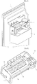
- Fig. 1 is a partial perspective view illustrating an ice maker according to an embodiment is mounted on a refrigerator door
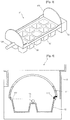
- Fig. 2 is a perspective view illustrating an ice maker according to an embodiment
- Fig. 3 is a perspective view illustrating an ice tray forming an ice maker according to an embodiment
- Fig. 4 is a vertical cross- sectional view illustrating a crucial portion of an embodiment
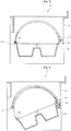
- Fig. 5 is a view illustrating a process in which an ice tray rotates according to an embodiment.
- the ice maker 10 is provided to a portion on the rear side of a refrigerator door 1. Also, an ice bank 2 is detachably installed on the rear side of the door 1 that corresponds to a lower portion blow the ice maker 10.
- the ice bank 2 stores ice made by the ice maker 10.
- the ice maker 10 can be provided to a freezing chamber door or a cooling chamber door.
- the ice maker 10 is preferably provided inside the freezing door.
- the ice maker 10 includes a frame 11 installed on the rear side of the door 1, an ice tray 12 rotatably installed to the frame 11, and a control box 13 in which various parts for rotating the ice tray 12 are mounted.
- the frame 11 rotatably supports the ice tray 12.
- a tray cover 111 for selectively opening/closing the ice tray 12 to prevent water stored in the ice tray 12 from flooding, and a twisting inducing part 1 1 2 for inducing twisting of the ice tray 12 are provided to the frame 11.
- the tray cover 111 is integrally formed with the frame 11.
- the tray cover 111 can be injection-molded integrally with the frame 11.
- the tray cover 111 may be separately manufactured and fixed to the frame 11.
- the tray cover 111 selectively opens/closes the ice tray 12 while the ice tray 12 rotates to move the ice. That is, during a process of storing water in the ice tray 12 or a process of making ice using the stored water, the tray cover 111 shields the ice tray 12. When the ice tray 12 rotates to move made ice, the tray cover 111 opens the ice tray 12.
- the tray cover 111 is formed in an about semi-cylindrical shape to prevent interference between the tray cover 111 and the ice tray 12 caused by rotation of the ice tray 12. This is because the ice tray 12 is formed in an about flat hexahedral shape, and rotates around a rotational shaft provided in a long side direction to a central portion on a side in a short side direction. Therefore, the shape of the tray cover 111 can change depending on the shape of the ice tray 12 and the location of the rotational shaft.
- a water supply opening 111A is formed in the tray cover 111.
- the water supply opening 111A is a portion through which water to be supplied to the ice tray 12 passes.
- the water supply opening 111A is formed by cutting a portion of the tray cover 111 in a predetermined shape.
- the twisting inducing part 112 protrudes such that a portion of the frame 11 is located on a rotation trace of the ice tray 12.
- the twisting inducing part 112 contacts one side of the ice tray 12 while the ice tray 12 rotates to separate the ice.
- the ice tray 12 is a portion where ice is substantially made.
- the ice tray 12 is twisted while it is rotated by a predetermined angle with respect to the frame 11 to separate the made ice.
- one side of the ice tray 12 contacts the twisting inducing part 112, so that the ice tray 12 is twisted.
- the twisting of the ice tray 12 allows the separated ice to fall down into the ice bank 2 and be stored therein.
- a motor (not shown) and a plurality of gears (not shown), and a controller (not shown) are provided inside the control box 13.
- the motor provides driving force for rotating the ice tray 12, and the gears deliver the driving force of the motor to the ice tray 12.
- the controller controls driving of the motor.
- a plurality of ice cubes 121 are provided to the ice tray 12.
- the ice cubes 121 substantially store water supplied through the water supply opening 111A.
- the water stored in the ice cubes 121 is frozen by cooling air circulating through the freezing chamber, so that ice is made.
- water flood prevention ribs 122 are provided to the ice tray 12.
- the water flood prevention ribs 1 22 extend upward to a predetermined height from the upper edge of the ice tray 12.
- the water flood prevention ribs 122 are designed for preventing water stored in the ice cubes 121 from flooding due to centrifugal force generated while the door 1 is opened/closed.
- the water flood prevention ribs 122 corresponding to the corners of the ice tray 12 may be formed to a height at least greater than a height of the water flood prevention ribs 122 corresponding to the other portions of the ice tray 12. This is because the water stored in the ice cubes 121 leans to the corner portions of the ice tray 12 by centrifugal force generated while the door 1 rotates.
- a rotation guide 123 is provided to the upper surface in the short side direction of the ice tray 1 2.
- the rotation guide 123 is intended for guiding rotation of the ice tray 12.
- the rotation guide 123 is formed in an about semicircular disk shape corresponding to the vertical cross-section of the tray cover 111 and extends to the upward direction of the ice tray 12.
- the rotation guide 123 moves along the inner surface of the tray cover 111 while the ice tray 12 rotates. Also, since the rotation guide 123 extends upward on the upper surface of the tray cover 111, it substantially prevents the water stored in the ice cubes 121 from flooding.
- Rotational shafts 124 are provided on side surfaces in the short side direction of the ice tray 121.
- the rotational shaft 124 serves as a rotational center of the ice tray 121 rotating to separate the ice.
- the rotational shaft 124 extends from the side surface in the short side direction to the long side direction, and is rotatably connected to the frame 11. Also, the gears for delivering driving force of the motor is connected to one of the rotational shafts 124.
- a sealing member 113 is provided to the lower end of the tray cover 111.
- the sealing member 113 is intended for preventing water stored in the ice cubes 121 from flooding.
- the scaling member 113 is closely attached on the upper end of the water flood prevention rib 1 22 provided to the upper one end of the ice tray 12 relatively rising while the ice tray 12 rotates.
- the sealing member 113 protrudes toward the ice tray 12 such that at least a portion of the sealing member 113 is located on a rotation trace of the ice tray 12 at the lower end of the tray cover 112.
- the sealing member 113 is formed of a material having predetermined elasticity, for example, silicon. Therefore, the sealing member 113 is elastically deformed by the ice tray 12 while the ice tray 12 rotates to separate ice. That is, the sealing member 113 is elastically deformed upward or downward by the ice tray 12 while the ice tray 12 rotates.
- the lower end of the tray cover 112 corresponding to the opposite side of the sealing member 113 that is, the lower end of the tray cover 112 corresponding to one end of the ice tray 12 that descends while the ice tray 12 rotates to separate the ice, is closely attached on the corresponding outer surface of the water flood prevention rib 1 22.
- Water supplied through the water supply opening 111A is stored in the ice cubes 121.
- the water stored in the ice cubes 121 does not flood due to contact between the tray cover 111 and the water flood prevention rib 122, and contact between the water flood prevention rib 122 and the sealing member 113 even when the door 1 rotates. Also, the water stored in the ice cubes 121 is frozen by cooling air circulating through the freezing chamber, so that ice is made.
- a controller drives a motor. Driving force of the motor is delivered to the ice tray 12 through gears. Therefore, rotation of the ice tray 12 is guided by the rotation guide 123 moving along the inner surface of the tray cover 111. [49] The ice tray 12 continues to rotate after it has rotated by a predetermined angle, and is twisted by the twisting inducing part 112. When the ice tray 12 is twisted, made ice is separated from the ice cubes 121 and stored in the ice bank 2. Description of the same construction as that of the previous embodiment is omitted.
- Fig. 6 is a perspective view illustrating an ice maker according to another embodiment
- Fig. 7 is a vertical cross-sectional view illustrating a crucial portion of another embodiment
- Fig. 8 is a view illustrating a process in which an ice tray rotates according to another embodiment. Descriptions for the same parts as those of the previous embodiment are omitted.
- a tray cover 211 and a water flood prevention rib 222 contact each other more solidly to prevent water stored in the ice tray 22 from flooding.
- a water flood prevention groove 214 is provided to the tray cover 211, and an elastic member 24 is provided between the frame 21 and the tray cover 211.
- the water flood prevention groove 214 is formed in a V shape by recessing a portion of the lower end of the tray cover 211 upward such that the portion is open approximately downward.
- the water flood prevention rib 222 is selectively inserted into the water flood prevention groove 214 as the ice tray 22 rotates.
- the water flood prevention groove 214 is provided to the lower end of the tray cover 211 that corresponds to one end of the ice tray 22 relatively descending while the ice tray 22 rotates to separate ice.
- the opposite side of the water flood prevention groove 214 that is, the lower end of the tray cover 211 that corresponds to one end of the ice tray 22 relatively rising while the ice tray 22 rotates to separate ice is closely attached on the outer surface of the water flood prevention rib 222.
- the elastic member 24 is provided between the tray cover 211 closely attached on the outer surface of the water flood prevention rib 222 and the frame 21.
- the upper end of the water flood prevention rib 222 is inserted into the water flood prevention groove 214 at one end of the tray cover 211.
- the other end of the tray cover 211 is closely attached on the outer surface of the water flood prevention rib 222 by elastic force of the elastic member 24. Therefore, flooding of water stored in the ice tray 22 can be more efficiently prevented while the refrigerator door is opened/closed.
- examples of the elastic member 24 include various types of springs. That is, for example, the elastic member 24 can be a torsion spring illustrated in Fig. 6 , or a coil spring illustrated in Fig. 8 .
- Fig. 9 is a vertical cross-sectional view illustrating a crucial portion of an ice maker according to still another embodiment
- Fig. 10 is a view illustrating a process in which an ice tray rotates according to still another embodiment. Descriptions for the same parts as those of the previous embodiment are omitted.
- a blocking rib 315 provided on the inner surface of the tray cover 311.
- the blocking rib 315 can be substantially formed integrally with the tray cover 311.
- the blocking rib 315 selectively contacts the upper surface of the ice tray 32, that is, the upper surface of the water flood prevention rib 322 as the ice tray 32 rotates.
- the blocking rib 315 protrudes from the inner surface of the tray cover 311 that corresponds to one end of the ice tray 32 relatively rising while the ice tray 32 rotates to separate ice. At least a portion of the blocking rib 315 is located on a rotation trace of the ice tray 32. Therefore, the ice tray 32 slides over the blocking rib 315 while the ice tray 32 rotates to separate the ice. At this point, the tray cover 311 may be elastically deformed by the projected length of the blocking rib 315.
- a water flood prevention groove 314 corresponding to the water flood prevention groove 214 of the previous embodiment can be formed at one end of the tray cover 311 that corresponds to the opposite side of the blocking rib 315, that is, one end of the tray cover 311 that corresponds to one end of the ice tray 32 relatively falling while the ice tray 32 rotates to separate the ice.
- Fig. 11 is a vertical cross-sectional view illustrating a crucial portion of an ice maker according to still another embodiment
- Fig. 12 is a view illustrating a process in which an ice tray rotates according to yet another embodiment. Descriptions for the same parts as those of the previous embodiment arc omitted.
- a contact area of the lower end of a tray cover 411 and the upper end of a water flood prevention rib 422 is increased, so that flooding of water stored in an ice tray 42 is more efficiently prevented.
- an inclined plane 416 formed at a predetermined angle is provided at the lower end of the tray cover 411.
- an inclined plane 423 formed in an angle matching with the inclined plane 416 of the tray cover 411 is provided at the upper end of the water flood prevention rib 422 that corresponds to the inclined plane 416 of the tray cover 411.
- the inclined planes 416 and 423 are provided, respectively, at the lower end of the tray cover 411 and the upper end of the water flood prevention rib 422 that correspond to one end of the ice tray 42 relatively rising while the ice tray 42 rotates to separate the ice.
- the inclined plane 423 of the water flood prevention rib 422 may slide along the inclined plane 416 of the tray cover 411 to prevent one end of the ice tray 42 from interfering with the inclined plane 416 of the tray cover 411 and the inclined plane 423 of the water flood prevention rib 422.
- the inclined plane 416 of the tray cover 411 may be inclined downward toward the outer side of the tray cover 411, and the inclined plane 423 of the water flood prevention rib 422 may be inclined upward toward the inner side of the water flood prevention rib 422 so that it matches with the inclined plane 416 of the tray cover 411.
- the lower end of the tray cover 411 that corresponds to the opposite side of the inclined planes 416 and 423, that is, the lower end of the tray cover 411 that corresponds to one end of the ice tray 42 relatively falling while the ice tray 42 rotates to separate the ice, is closely attached on the corresponding outer surface of the water flood prevention rib 422.
- the inclined planes 416 and 423 are provided, respectively, only at the lower end of the tray cover 411 and the upper end of the water flood prevention rib 422 that correspond to one end of the ice tray 42 relatively rising while the ice tray 42 rotates to separate the ice in the embodiment, an inclined plane can be provided also at the lower end of the tray cover 411 and the upper end of the water flood prevention rib 423 that correspond to the opposite side of the one end of the ice tray 42.
- the water flood prevention grooves 214 and 314 of the previous embodiments may be formed at the lower end of the tray cover 411 that corresponds to the opposite side of the inclined plane 416.
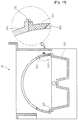
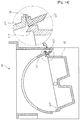
- Fig. 13 is a vertical cross-sectional view illustrating a crucial portion of an ice maker according to an embodiment of the invention
- Fig. 14 is a view illustrating a process in which an ice tray rotates according to still another embodiment.
- a rotation cooperating portion 517 rotating with respect to the tray cover 511 in cooperation with rotation of the ice tray 52.
- the rotation cooperating portion 517 is rotatably connected to the lower end of a tray cover 511 that corresponds to one end of an ice tray 52 relatively rising while the ice tray 52 rotates to separate ice.
- the lower end of the rotation cooperating portion 517 is closely attached on the upper end of a water flood prevention rib 522.
- the lower end of the rotation cooperating portion 517 and the upper end of the water flood prevention rib 522 may have the same inclined planes as the inclined planes 416 and 423 provided to the tray cover 411 and the water flood prevention rib 422 of the previous embodiment.
- An elastic member 55 is provided to give the rotation cooperating portion 517 elastic force in a direction contacting the water flood prevention rib 522.
- the elastic member 55 substantially connects the tray cover 511 and the rotation cooperating portion 517.
- the rotation cooperating portion 517 is closely attached on the water flood prevention rib 522 by elastic force of the elastic member 55. With this state, when the ice tray 52 rotates to separate ice, the rotation cooperating portion 517 rotates by the rotation of the ice tray 52, so that the rotation cooperating portion 517 is separated from the water flood prevention portion 522.
- the lower end of the tray cover 511 that corresponds to the opposite side of the rotation cooperating portion 517 can be closely attached on the outer surface of the water flood prevention rib 522 as in the previous embodiments.
- a water flood prevention groove for receiving the upper end of the water flood prevention rib 522 can be formed in the lower end of the tray cover 511 also in the embodiment.
- An ice maker and a refrigerator including the same according to the present invention provide the following effects.
- an ice maker is mounted in a refrigerator door. Accordingly, the ice maker prevents reduction in the storage capacity of a storage space of a refrigerator, so that a larger amount of food can be stored in the refrigerator.
- elements such as a tray cover and a water flood prevention rib are provided to prevent water stored in an ice tray from flooding. Accordingly, flooding of the water stored in the ice tray is prevented while a refrigerator door is opened/closed.
- rotation of an ice tray is guided by a rotation guide. Therefore, the operation of an ice maker is more efficiently performed, so that user utility increases.
Landscapes
- Engineering & Computer Science (AREA)
- Physics & Mathematics (AREA)
- Mechanical Engineering (AREA)
- Thermal Sciences (AREA)
- General Engineering & Computer Science (AREA)
- Chemical & Material Sciences (AREA)
- Combustion & Propulsion (AREA)
- Production, Working, Storing, Or Distribution Of Ice (AREA)
Claims (14)
- Machine à glaçons, comprenant :un cadre prévu sur une face arrière d'une porte de réfrigérateur ;un bac à glaçons (52) monté de manière rotative dans le cadre ;un couvercle de bac (511) prévu sur le cadre et ouvrant ou fermant sélectivement le bac à glaçons quand le bac à glaçons tourne, etune portion de coopération de rotation (517) raccordée de manière rotative au couvercle de bac (511) et touchant sélectivement une surface supérieure du bac à glaçons (52) ; etun élément élastique (55) pour donner une force élastique à la portion de coopération de rotation (517) de sorte que la portion de coopération de rotation (517) tourne dans une direction telle qu'elle touche la surface supérieure du bac à glaçons (52).
- Machine à glaçons selon la revendication 1, où la portion de coopération de rotation (517) tourne dans une direction en se séparant de la surface supérieure du bac à glaçons (52) lorsque le bac à glaçons (52) tourne, et tourne en utilisant la force élastique de l'élément élastique (55) pour toucher la surface supérieure du bac à glaçons (52) lorsque le bac à glaçons (52) est rétabli dans une position initiale.
- Machine à glaçons selon la revendication 2, où la surface supérieure du bac à glaçons (52) et une extrémité inférieure de la portion de coopération de rotation (517) présentent des portions inclinées respectivement, les portions inclinées correspondant les unes aux autres.
- Machine à glaçons selon l'une quelconque des revendications précédentes, comprenant en outre une nervure anti-débordement d'eau (522) s'étendant depuis un bord supérieur du bac à glaçons (52), et empêchant l'eau stockée dans le bac à glaçons (52) de déborder quand la porte du réfrigérateur tourne.
- Machine à glaçons selon la revendication 4, où une hauteur d'une partie de la nervure anti-débordement d'eau (522) qui correspond à une partie de bord du bac à glaçons est égale ou supérieure à celle de l'autre partie de la nervure anti-débordement d'eau (522) qui correspond à la partie restante du bac à glaçons.
- Machine à glaçons selon la revendication 5, où une d'une extrémité inférieure du couvercle de bac (511) et d'une extrémité supérieure correspondante de la nervure anti-débordement d'eau (522) est sélectivement insérée l'une dans l'autre quand le bac à glaçons tourne.
- Machine à glaçons selon la revendication 6, où l'extrémité supérieure de la nervure anti-débordement d'eau (522) qui correspond à un côté du bac à glaçons (52) tombant relativement quand le bac à glaçons tourne pour séparer la glace est insérée dans une nervure anti-débordement d'eau formée dans l'extrémité inférieure du couvercle de bac.
- Machine à glaçons selon la revendication 1, où au moins une portion du couvercle de bac est étroitement attachée sur une surface supérieure du bac à glaçons.
- Machine à glaçons selon la revendication 1, où le couvercle de bac (511) est formé pour correspondre à une trace de rotation du bac à glaçons (52) pour empêcher l'interférence avec le bac à glaçons rotatif.
- Machine à glaçons selon la revendication 4, où l'extrémité inférieure du couvercle de bac (511) et l'extrémité supérieure correspondante de la nervure anti-débordement d'eau (522) sont formées pour correspondre l'une à l'autre, et toucher sélectivement l'une l'autre lorsque le bac à glaçons (52) tourne.
- Machine à glaçons selon la revendication 10, où une portion inclinée sur l'extrémité supérieure de la nervure anti-débordement d'eau correspond à un côté du bac à glaçons (52) est étroitement attachée sur l'autre portion inclinée sur l'extrémité inférieure du couvercle de bac (511) à un angle correspondant.
- Machine à glaçons selon la revendication 1, où le couvercle de bac (511) est formé dans une forme semi-cylindrique correspondant à une trace de rotation du bac à glaçons (52), et un guidage de rotation (123) prévu sur le bac à glaçons et guidant la rotation du bac à glaçons est formé dans une forme correspondant à une section transversale verticale du couvercle de bac (511).
- Machine à glaçons selon la revendication 12, où le guidage de rotation (123) est prévu sur une surface supérieure du bac à glaçons (52) de sorte que le guidage de rotation (123) soit perpendiculaire à un arbre de rotation (124) du bac à glaçons (52) pour se déplacer le long d'une surface intérieure du couvercle de bac (511) lorsque le bac à glaçons (52) tourne.
- Réfrigérateur, comprenant :une carrosserie principale comprenant un espace de stockage ;une porte (1) pour l'ouverture/la fermeture sélectives de l'espace de stockage ; etune machine à glaçons (10) selon l'une des revendications 1 à 13.
Applications Claiming Priority (3)
| Application Number | Priority Date | Filing Date | Title |
|---|---|---|---|
| KR1020060080207A KR100863389B1 (ko) | 2006-08-24 | 2006-08-24 | 냉장고 및 냉장고의 제빙 장치 |
| EP07793577.3A EP2054681B1 (fr) | 2006-08-24 | 2007-08-20 | Appareil à fabriquer de la glace et réfrigérateur contenant ledit appareil |
| PCT/KR2007/003973 WO2008023911A1 (fr) | 2006-08-24 | 2007-08-20 | Appareil à fabriquer de la glace et réfrigérateur contenant ledit appareil |
Related Parent Applications (2)
| Application Number | Title | Priority Date | Filing Date |
|---|---|---|---|
| EP07793577.3A Division EP2054681B1 (fr) | 2006-08-24 | 2007-08-20 | Appareil à fabriquer de la glace et réfrigérateur contenant ledit appareil |
| EP07793577.3A Division-Into EP2054681B1 (fr) | 2006-08-24 | 2007-08-20 | Appareil à fabriquer de la glace et réfrigérateur contenant ledit appareil |
Publications (2)
| Publication Number | Publication Date |
|---|---|
| EP3406991A1 EP3406991A1 (fr) | 2018-11-28 |
| EP3406991B1 true EP3406991B1 (fr) | 2021-04-07 |
Family
ID=39106967
Family Applications (5)
| Application Number | Title | Priority Date | Filing Date |
|---|---|---|---|
| EP17192320.4A Active EP3296667B1 (fr) | 2006-08-24 | 2007-08-20 | Réfrigérateur comprenant un appareil de fabrication de glaçons |
| EP07793577.3A Active EP2054681B1 (fr) | 2006-08-24 | 2007-08-20 | Appareil à fabriquer de la glace et réfrigérateur contenant ledit appareil |
| EP23164007.9A Active EP4227613B1 (fr) | 2006-08-24 | 2007-08-20 | Réfrigérateur |
| EP17192322.0A Active EP3296668B1 (fr) | 2006-08-24 | 2007-08-20 | Porte de réfrigérateur avec un appareil de fabrication de glaçons et réfrigérateur comprenant une telle porte |
| EP18177035.5A Active EP3406991B1 (fr) | 2006-08-24 | 2007-08-20 | Appareil de fabrication de glaçons et réfrigérateur comprenant un tel appareil |
Family Applications Before (4)
| Application Number | Title | Priority Date | Filing Date |
|---|---|---|---|
| EP17192320.4A Active EP3296667B1 (fr) | 2006-08-24 | 2007-08-20 | Réfrigérateur comprenant un appareil de fabrication de glaçons |
| EP07793577.3A Active EP2054681B1 (fr) | 2006-08-24 | 2007-08-20 | Appareil à fabriquer de la glace et réfrigérateur contenant ledit appareil |
| EP23164007.9A Active EP4227613B1 (fr) | 2006-08-24 | 2007-08-20 | Réfrigérateur |
| EP17192322.0A Active EP3296668B1 (fr) | 2006-08-24 | 2007-08-20 | Porte de réfrigérateur avec un appareil de fabrication de glaçons et réfrigérateur comprenant une telle porte |
Country Status (5)
| Country | Link |
|---|---|
| US (1) | US8689578B2 (fr) |
| EP (5) | EP3296667B1 (fr) |
| KR (1) | KR100863389B1 (fr) |
| CN (1) | CN101490486B (fr) |
| WO (1) | WO2008023911A1 (fr) |
Families Citing this family (22)
| Publication number | Priority date | Publication date | Assignee | Title |
|---|---|---|---|---|
| CN101315240A (zh) * | 2008-06-26 | 2008-12-03 | 海尔集团公司 | 一种制冰机及包含该制冰机的冰箱 |
| KR101622595B1 (ko) * | 2008-11-19 | 2016-05-19 | 엘지전자 주식회사 | 제빙장치 및 이를 구비한 냉장고 및 이 냉장고의 제빙방법 |
| AU2009343710B2 (en) | 2009-04-01 | 2012-08-30 | Lg Electronics Inc. | Refrigerator having ice making device |
| KR101649631B1 (ko) * | 2009-10-26 | 2016-08-19 | 엘지전자 주식회사 | 냉장고의 제빙장치 및 이를 구비한 냉장고 |
| KR101659006B1 (ko) * | 2009-10-26 | 2016-09-30 | 엘지전자 주식회사 | 냉장고의 제빙장치 및 이를 구비한 냉장고 |
| CN102128530B (zh) * | 2010-01-14 | 2015-06-24 | 海尔集团公司 | 用于电冰箱的制冰机的挡水装置 |
| EP2539648B1 (fr) * | 2010-02-23 | 2019-05-01 | LG Electronics Inc. | Machine à glaçons, réfrigérateur ayant celle-ci, et procédé de distribution de glaçons de celui-ci |
| KR101690126B1 (ko) * | 2010-03-09 | 2016-12-27 | 엘지전자 주식회사 | 제빙장치 및 이를 구비한 냉장고 |
| KR101621568B1 (ko) * | 2010-08-19 | 2016-05-17 | 엘지전자 주식회사 | 제빙장치 |
| CN102914110B (zh) * | 2012-11-01 | 2016-03-30 | 合肥华凌股份有限公司 | 冰箱及其制冰机 |
| US9557087B2 (en) * | 2012-12-13 | 2017-01-31 | Whirlpool Corporation | Clear ice making apparatus having an oscillation frequency and angle |
| PL3175187T3 (pl) * | 2014-08-01 | 2020-05-18 | Arçelik Anonim Şirketi | Lodówka zawierająca jednostkę do wytwarzania lodu |
| JP6567978B2 (ja) * | 2016-01-18 | 2019-08-28 | 日立グローバルライフソリューションズ株式会社 | 冷蔵庫 |
| US20180245832A1 (en) * | 2016-07-28 | 2018-08-30 | Dae Chang Co., Ltd. | Ice maker and refrigerator including the same |
| JP7079780B2 (ja) * | 2017-07-14 | 2022-06-02 | シャープ株式会社 | 製氷ユニット |
| JP7085830B2 (ja) * | 2017-12-22 | 2022-06-17 | 日本電産サンキョー株式会社 | 製氷機 |
| WO2020071791A1 (fr) * | 2018-10-02 | 2020-04-09 | 엘지전자 주식회사 | Réfrigérateur et procédé de commande associé |
| WO2020101370A1 (fr) | 2018-11-16 | 2020-05-22 | 엘지전자 주식회사 | Machine à glaçons et réfrigérateur |
| CN109849254A (zh) * | 2018-11-21 | 2019-06-07 | 合肥雪祺电气有限公司 | 一种冰箱自动发泡堵漏装置 |
| US11002476B2 (en) * | 2019-04-01 | 2021-05-11 | Haier Us Appliance Solutions, Inc. | Ice maker having a splash cover |
| JP7373186B2 (ja) * | 2019-09-18 | 2023-11-02 | アクア株式会社 | 製氷装置及び製氷装置を備えた冷蔵庫 |
| US11846462B2 (en) | 2021-03-19 | 2023-12-19 | Electrolux Home Products, Inc. | Door mounted chilled component with direct cooling |
Family Cites Families (17)
| Publication number | Priority date | Publication date | Assignee | Title |
|---|---|---|---|---|
| JP2609741B2 (ja) * | 1990-04-26 | 1997-05-14 | 株式会社東芝 | 自動製氷装置付冷蔵庫 |
| JPH05296623A (ja) * | 1992-04-17 | 1993-11-09 | Hitachi Ltd | 自動製氷機付き冷蔵庫 |
| JPH0594668U (ja) * | 1992-05-26 | 1993-12-24 | シャープ株式会社 | 自動製氷装置 |
| JPH0611228A (ja) | 1992-06-29 | 1994-01-21 | Hitachi Ltd | 自動製氷機付き冷蔵庫 |
| JPH06185841A (ja) | 1992-12-15 | 1994-07-08 | Sharp Corp | 自動製氷装置 |
| JPH06241626A (ja) * | 1993-02-23 | 1994-09-02 | Sharp Corp | 自動製氷装置 |
| KR100202064B1 (ko) * | 1996-08-31 | 1999-06-15 | 전주범 | 제빙기의 제빙그릇 이빙장치 |
| DE10221897B4 (de) * | 2002-05-16 | 2005-03-10 | Bsh Bosch Siemens Hausgeraete | Kältegerät und Eisbereiter dafür |
| EP1482261B1 (fr) * | 2003-05-28 | 2014-01-01 | LG Electronics, Inc. | Système de distribution de glace |
| KR100693578B1 (ko) * | 2003-11-27 | 2007-03-14 | 엘지전자 주식회사 | 냉장고용 아이스 메이커 |
| KR20050110213A (ko) | 2004-05-18 | 2005-11-23 | 주식회사 대창 | 제빙기 |
| US7437885B2 (en) * | 2004-10-26 | 2008-10-21 | Whirlpool Corporation | Water spillage management for in the door ice maker |
| DE102005003238A1 (de) * | 2005-01-24 | 2006-07-27 | BSH Bosch und Siemens Hausgeräte GmbH | Eisbereiter |
| WO2007066958A1 (fr) * | 2005-12-06 | 2007-06-14 | Lg Electronics Inc. | Dispositif de fabrication de glace d'un refrigerateur, et refrigerateur possedant ce dispositif |
| DE202006008063U1 (de) * | 2006-05-19 | 2006-07-20 | BSH Bosch und Siemens Hausgeräte GmbH | Kältegerät mit Eisbereiter |
| US8104304B2 (en) * | 2006-06-29 | 2012-01-31 | Lg Electronics Inc. | Ice making device for refrigerator |
| KR100871269B1 (ko) * | 2006-08-25 | 2008-11-28 | 엘지전자 주식회사 | 제빙기 및 이를 포함하는 냉장고 |
-
2006
- 2006-08-24 KR KR1020060080207A patent/KR100863389B1/ko active Active
-
2007
- 2007-08-20 EP EP17192320.4A patent/EP3296667B1/fr active Active
- 2007-08-20 EP EP07793577.3A patent/EP2054681B1/fr active Active
- 2007-08-20 EP EP23164007.9A patent/EP4227613B1/fr active Active
- 2007-08-20 WO PCT/KR2007/003973 patent/WO2008023911A1/fr not_active Ceased
- 2007-08-20 CN CN2007800271919A patent/CN101490486B/zh active Active
- 2007-08-20 US US12/375,268 patent/US8689578B2/en active Active
- 2007-08-20 EP EP17192322.0A patent/EP3296668B1/fr active Active
- 2007-08-20 EP EP18177035.5A patent/EP3406991B1/fr active Active
Non-Patent Citations (1)
| Title |
|---|
| None * |
Also Published As
| Publication number | Publication date |
|---|---|
| KR20080018304A (ko) | 2008-02-28 |
| EP2054681B1 (fr) | 2018-08-08 |
| CN101490486A (zh) | 2009-07-22 |
| EP3296667A1 (fr) | 2018-03-21 |
| EP3296667B1 (fr) | 2023-03-01 |
| EP4227613A1 (fr) | 2023-08-16 |
| CN101490486B (zh) | 2011-04-13 |
| EP2054681A4 (fr) | 2014-10-01 |
| EP3296668A1 (fr) | 2018-03-21 |
| US8689578B2 (en) | 2014-04-08 |
| EP4227613B1 (fr) | 2024-07-10 |
| EP3296668B1 (fr) | 2023-04-19 |
| WO2008023911A1 (fr) | 2008-02-28 |
| KR100863389B1 (ko) | 2008-10-13 |
| US20100037646A1 (en) | 2010-02-18 |
| EP2054681A1 (fr) | 2009-05-06 |
| EP3406991A1 (fr) | 2018-11-28 |
Similar Documents
| Publication | Publication Date | Title |
|---|---|---|
| EP3406991B1 (fr) | Appareil de fabrication de glaçons et réfrigérateur comprenant un tel appareil | |
| EP2059734B1 (fr) | Réfrigérateur | |
| KR101504214B1 (ko) | 디스펜서를 구비한 냉장고 | |
| EP2054680B1 (fr) | Machine à fabriquer de la glace | |
| WO2008002023A1 (fr) | Dispositif de production de glace pour réfrigérateur | |
| EP2674703A1 (fr) | Réfrigérateur | |
| KR20080103350A (ko) | 냉장고용 아이스트레이와 제빙유닛 및 이를 포함하는제빙장치 | |
| CN103069227A (zh) | 冰箱 | |
| CN101384871A (zh) | 冰箱用的制冰装置 | |
| US20100275635A1 (en) | Ice making apparatus and refrigerator comprising the same | |
| WO2008100018A1 (fr) | Dispositif de fabrication de glace et réfrigérateur | |
| US11209200B2 (en) | Refrigerator and ice-making assembly | |
| KR101258437B1 (ko) | 제빙유닛 및 이를 구비하는 냉장고 | |
| KR101334958B1 (ko) | 냉장고용 물탱크 및 이를 포함하는 제빙장치 | |
| CN112771326A (zh) | 冰箱 | |
| KR101225974B1 (ko) | 냉장고용 물탱크 및 이를 포함하는 냉장고용 제빙장치 | |
| EP4603770A1 (fr) | Réfrigérateur | |
| EP4603771A1 (fr) | Réfrigérateur | |
| JP7076560B2 (ja) | 自動製氷機 | |
| KR20220060006A (ko) | 제빙기 및 이를 포함하는 냉장고 | |
| KR101183325B1 (ko) | 냉장고 및 냉장고의 제빙 장치 |
Legal Events
| Date | Code | Title | Description |
|---|---|---|---|
| PUAI | Public reference made under article 153(3) epc to a published international application that has entered the european phase |
Free format text: ORIGINAL CODE: 0009012 |
|
| STAA | Information on the status of an ep patent application or granted ep patent |
Free format text: STATUS: REQUEST FOR EXAMINATION WAS MADE |
|
| 17P | Request for examination filed |
Effective date: 20180711 |
|
| AC | Divisional application: reference to earlier application |
Ref document number: 2054681 Country of ref document: EP Kind code of ref document: P |
|
| AK | Designated contracting states |
Kind code of ref document: A1 Designated state(s): DE FR GB IT NL |
|
| RBV | Designated contracting states (corrected) |
Designated state(s): DE FR GB IT NL |
|
| GRAP | Despatch of communication of intention to grant a patent |
Free format text: ORIGINAL CODE: EPIDOSNIGR1 |
|
| STAA | Information on the status of an ep patent application or granted ep patent |
Free format text: STATUS: GRANT OF PATENT IS INTENDED |
|
| INTG | Intention to grant announced |
Effective date: 20201020 |
|
| GRAS | Grant fee paid |
Free format text: ORIGINAL CODE: EPIDOSNIGR3 |
|
| GRAA | (expected) grant |
Free format text: ORIGINAL CODE: 0009210 |
|
| STAA | Information on the status of an ep patent application or granted ep patent |
Free format text: STATUS: THE PATENT HAS BEEN GRANTED |
|
| AC | Divisional application: reference to earlier application |
Ref document number: 2054681 Country of ref document: EP Kind code of ref document: P |
|
| AK | Designated contracting states |
Kind code of ref document: B1 Designated state(s): DE FR GB IT NL |
|
| REG | Reference to a national code |
Ref country code: GB Ref legal event code: FG4D |
|
| REG | Reference to a national code |
Ref country code: DE Ref legal event code: R096 Ref document number: 602007061052 Country of ref document: DE |
|
| REG | Reference to a national code |
Ref country code: NL Ref legal event code: MP Effective date: 20210407 |
|
| PG25 | Lapsed in a contracting state [announced via postgrant information from national office to epo] |
Ref country code: NL Free format text: LAPSE BECAUSE OF FAILURE TO SUBMIT A TRANSLATION OF THE DESCRIPTION OR TO PAY THE FEE WITHIN THE PRESCRIBED TIME-LIMIT Effective date: 20210407 |
|
| REG | Reference to a national code |
Ref country code: DE Ref legal event code: R097 Ref document number: 602007061052 Country of ref document: DE |
|
| PLBE | No opposition filed within time limit |
Free format text: ORIGINAL CODE: 0009261 |
|
| STAA | Information on the status of an ep patent application or granted ep patent |
Free format text: STATUS: NO OPPOSITION FILED WITHIN TIME LIMIT |
|
| 26N | No opposition filed |
Effective date: 20220110 |
|
| P01 | Opt-out of the competence of the unified patent court (upc) registered |
Effective date: 20230527 |
|
| PGFP | Annual fee paid to national office [announced via postgrant information from national office to epo] |
Ref country code: DE Payment date: 20250707 Year of fee payment: 19 |
|
| PGFP | Annual fee paid to national office [announced via postgrant information from national office to epo] |
Ref country code: IT Payment date: 20250710 Year of fee payment: 19 |
|
| PGFP | Annual fee paid to national office [announced via postgrant information from national office to epo] |
Ref country code: GB Payment date: 20250707 Year of fee payment: 19 |
|
| PGFP | Annual fee paid to national office [announced via postgrant information from national office to epo] |
Ref country code: FR Payment date: 20250715 Year of fee payment: 19 |