EP3407062A1 - Système de détection d'hydrogène à guide d'ondes diélectrique - Google Patents
Système de détection d'hydrogène à guide d'ondes diélectrique Download PDFInfo
- Publication number
- EP3407062A1 EP3407062A1 EP17172215.0A EP17172215A EP3407062A1 EP 3407062 A1 EP3407062 A1 EP 3407062A1 EP 17172215 A EP17172215 A EP 17172215A EP 3407062 A1 EP3407062 A1 EP 3407062A1
- Authority
- EP
- European Patent Office
- Prior art keywords
- hydrogen
- sensing layer
- sensor
- hpwg
- layer
- Prior art date
- Legal status (The legal status is an assumption and is not a legal conclusion. Google has not performed a legal analysis and makes no representation as to the accuracy of the status listed.)
- Withdrawn
Links
- 239000001257 hydrogen Substances 0.000 title claims abstract description 165
- 229910052739 hydrogen Inorganic materials 0.000 title claims abstract description 165
- 125000004435 hydrogen atom Chemical class [H]* 0.000 title description 2
- UFHFLCQGNIYNRP-UHFFFAOYSA-N Hydrogen Chemical compound [H][H] UFHFLCQGNIYNRP-UHFFFAOYSA-N 0.000 claims abstract description 110
- 150000002431 hydrogen Chemical class 0.000 claims abstract description 57
- 238000010521 absorption reaction Methods 0.000 claims abstract description 36
- 238000001514 detection method Methods 0.000 claims abstract description 28
- 230000003197 catalytic effect Effects 0.000 claims abstract description 23
- 230000001902 propagating effect Effects 0.000 claims abstract description 20
- 230000008859 change Effects 0.000 claims abstract description 17
- 230000001419 dependent effect Effects 0.000 claims abstract description 15
- 238000000034 method Methods 0.000 claims abstract description 11
- 239000012466 permeate Substances 0.000 claims abstract description 6
- 230000005684 electric field Effects 0.000 claims description 20
- 230000008878 coupling Effects 0.000 claims description 18
- 238000010168 coupling process Methods 0.000 claims description 18
- 238000005859 coupling reaction Methods 0.000 claims description 18
- 239000000758 substrate Substances 0.000 claims description 18
- VYPSYNLAJGMNEJ-UHFFFAOYSA-N Silicium dioxide Chemical compound O=[Si]=O VYPSYNLAJGMNEJ-UHFFFAOYSA-N 0.000 claims description 10
- 229910052751 metal Inorganic materials 0.000 claims description 9
- 239000002184 metal Substances 0.000 claims description 9
- 229910052681 coesite Inorganic materials 0.000 claims description 5
- 229910052906 cristobalite Inorganic materials 0.000 claims description 5
- 238000005259 measurement Methods 0.000 claims description 5
- 229910052759 nickel Inorganic materials 0.000 claims description 5
- 229910052763 palladium Inorganic materials 0.000 claims description 5
- 239000000377 silicon dioxide Substances 0.000 claims description 5
- 229910052682 stishovite Inorganic materials 0.000 claims description 5
- 229910052905 tridymite Inorganic materials 0.000 claims description 5
- 229910052709 silver Inorganic materials 0.000 claims description 4
- 239000004332 silver Substances 0.000 claims description 4
- RYGMFSIKBFXOCR-UHFFFAOYSA-N Copper Chemical compound [Cu] RYGMFSIKBFXOCR-UHFFFAOYSA-N 0.000 claims description 3
- 238000006243 chemical reaction Methods 0.000 claims description 3
- 229910052802 copper Inorganic materials 0.000 claims description 3
- 239000010949 copper Substances 0.000 claims description 3
- PCHJSUWPFVWCPO-UHFFFAOYSA-N gold Chemical compound [Au] PCHJSUWPFVWCPO-UHFFFAOYSA-N 0.000 claims description 3
- 229910052737 gold Inorganic materials 0.000 claims description 3
- 239000010931 gold Substances 0.000 claims description 3
- 229910052697 platinum Inorganic materials 0.000 claims description 3
- 229910052723 transition metal Inorganic materials 0.000 claims description 3
- 229910052726 zirconium Inorganic materials 0.000 claims description 3
- 229910000980 Aluminium gallium arsenide Inorganic materials 0.000 claims description 2
- 229910001218 Gallium arsenide Inorganic materials 0.000 claims description 2
- BQCADISMDOOEFD-UHFFFAOYSA-N Silver Chemical compound [Ag] BQCADISMDOOEFD-UHFFFAOYSA-N 0.000 claims description 2
- 229910052782 aluminium Inorganic materials 0.000 claims description 2
- 239000004411 aluminium Substances 0.000 claims description 2
- XAGFODPZIPBFFR-UHFFFAOYSA-N aluminium Chemical compound [Al] XAGFODPZIPBFFR-UHFFFAOYSA-N 0.000 claims description 2
- 229910052715 tantalum Inorganic materials 0.000 claims description 2
- 229910052719 titanium Inorganic materials 0.000 claims description 2
- 150000003624 transition metals Chemical class 0.000 claims description 2
- 239000010410 layer Substances 0.000 description 134
- 239000003921 oil Substances 0.000 description 25
- 235000019198 oils Nutrition 0.000 description 25
- 230000003287 optical effect Effects 0.000 description 25
- 238000009413 insulation Methods 0.000 description 22
- 239000007788 liquid Substances 0.000 description 22
- 230000005540 biological transmission Effects 0.000 description 15
- 239000007789 gas Substances 0.000 description 15
- KDLHZDBZIXYQEI-UHFFFAOYSA-N Palladium Chemical compound [Pd] KDLHZDBZIXYQEI-UHFFFAOYSA-N 0.000 description 12
- 230000010287 polarization Effects 0.000 description 12
- 239000012530 fluid Substances 0.000 description 8
- PXHVJJICTQNCMI-UHFFFAOYSA-N nickel Substances [Ni] PXHVJJICTQNCMI-UHFFFAOYSA-N 0.000 description 7
- 238000009826 distribution Methods 0.000 description 6
- 230000006870 function Effects 0.000 description 6
- 239000000463 material Substances 0.000 description 6
- 230000035945 sensitivity Effects 0.000 description 6
- 230000008901 benefit Effects 0.000 description 4
- 230000001965 increasing effect Effects 0.000 description 4
- 239000012212 insulator Substances 0.000 description 4
- 229910001092 metal group alloy Inorganic materials 0.000 description 4
- 239000000203 mixture Substances 0.000 description 4
- 230000004044 response Effects 0.000 description 4
- 239000000126 substance Substances 0.000 description 4
- 239000011248 coating agent Substances 0.000 description 3
- 238000000576 coating method Methods 0.000 description 3
- 238000000354 decomposition reaction Methods 0.000 description 3
- 238000005984 hydrogenation reaction Methods 0.000 description 3
- BASFCYQUMIYNBI-UHFFFAOYSA-N platinum Substances [Pt] BASFCYQUMIYNBI-UHFFFAOYSA-N 0.000 description 3
- ZNOKGRXACCSDPY-UHFFFAOYSA-N tungsten(VI) oxide Inorganic materials O=[W](=O)=O ZNOKGRXACCSDPY-UHFFFAOYSA-N 0.000 description 3
- 229910045601 alloy Inorganic materials 0.000 description 2
- 239000000956 alloy Substances 0.000 description 2
- 230000015556 catabolic process Effects 0.000 description 2
- 238000004891 communication Methods 0.000 description 2
- 238000001816 cooling Methods 0.000 description 2
- 238000006731 degradation reaction Methods 0.000 description 2
- 238000012986 modification Methods 0.000 description 2
- 230000004048 modification Effects 0.000 description 2
- 239000013307 optical fiber Substances 0.000 description 2
- 230000008569 process Effects 0.000 description 2
- 239000011540 sensing material Substances 0.000 description 2
- 238000004088 simulation Methods 0.000 description 2
- 239000010409 thin film Substances 0.000 description 2
- YZCKVEUIGOORGS-UHFFFAOYSA-N Hydrogen atom Chemical compound [H] YZCKVEUIGOORGS-UHFFFAOYSA-N 0.000 description 1
- 235000019482 Palm oil Nutrition 0.000 description 1
- 230000002411 adverse Effects 0.000 description 1
- 125000004429 atom Chemical group 0.000 description 1
- QVGXLLKOCUKJST-UHFFFAOYSA-N atomic oxygen Chemical compound [O] QVGXLLKOCUKJST-UHFFFAOYSA-N 0.000 description 1
- 230000002238 attenuated effect Effects 0.000 description 1
- 230000004888 barrier function Effects 0.000 description 1
- 230000015572 biosynthetic process Effects 0.000 description 1
- 239000003054 catalyst Substances 0.000 description 1
- 238000006555 catalytic reaction Methods 0.000 description 1
- 229910052729 chemical element Inorganic materials 0.000 description 1
- 239000011247 coating layer Substances 0.000 description 1
- 230000007797 corrosion Effects 0.000 description 1
- 238000005260 corrosion Methods 0.000 description 1
- 230000007547 defect Effects 0.000 description 1
- 238000009792 diffusion process Methods 0.000 description 1
- 238000010616 electrical installation Methods 0.000 description 1
- 238000010292 electrical insulation Methods 0.000 description 1
- 230000002708 enhancing effect Effects 0.000 description 1
- 150000004678 hydrides Chemical class 0.000 description 1
- 230000006872 improvement Effects 0.000 description 1
- 230000000977 initiatory effect Effects 0.000 description 1
- 229910052500 inorganic mineral Inorganic materials 0.000 description 1
- 238000005468 ion implantation Methods 0.000 description 1
- 230000031700 light absorption Effects 0.000 description 1
- 238000001459 lithography Methods 0.000 description 1
- 230000007257 malfunction Effects 0.000 description 1
- 238000004519 manufacturing process Methods 0.000 description 1
- 230000007246 mechanism Effects 0.000 description 1
- 239000011707 mineral Substances 0.000 description 1
- 239000002480 mineral oil Substances 0.000 description 1
- 235000010446 mineral oil Nutrition 0.000 description 1
- 238000012806 monitoring device Methods 0.000 description 1
- 238000012544 monitoring process Methods 0.000 description 1
- 238000010397 one-hybrid screening Methods 0.000 description 1
- 230000001151 other effect Effects 0.000 description 1
- 238000013021 overheating Methods 0.000 description 1
- 239000001301 oxygen Substances 0.000 description 1
- 229910052760 oxygen Inorganic materials 0.000 description 1
- 239000002540 palm oil Substances 0.000 description 1
- 231100000572 poisoning Toxicity 0.000 description 1
- 230000000607 poisoning effect Effects 0.000 description 1
- 239000004810 polytetrafluoroethylene Substances 0.000 description 1
- 229920001343 polytetrafluoroethylene Polymers 0.000 description 1
- 238000007086 side reaction Methods 0.000 description 1
- 238000012360 testing method Methods 0.000 description 1
- XLYOFNOQVPJJNP-UHFFFAOYSA-N water Substances O XLYOFNOQVPJJNP-UHFFFAOYSA-N 0.000 description 1
- 238000004804 winding Methods 0.000 description 1
Images


Classifications
-
- G—PHYSICS
- G01—MEASURING; TESTING
- G01N—INVESTIGATING OR ANALYSING MATERIALS BY DETERMINING THEIR CHEMICAL OR PHYSICAL PROPERTIES
- G01N33/00—Investigating or analysing materials by specific methods not covered by groups G01N1/00 - G01N31/00
- G01N33/0004—Gaseous mixtures, e.g. polluted air
- G01N33/0009—General constructional details of gas analysers, e.g. portable test equipment
- G01N33/0027—General constructional details of gas analysers, e.g. portable test equipment concerning the detector
- G01N33/0036—General constructional details of gas analysers, e.g. portable test equipment concerning the detector specially adapted to detect a particular component
- G01N33/005—H2
-
- G—PHYSICS
- G01—MEASURING; TESTING
- G01N—INVESTIGATING OR ANALYSING MATERIALS BY DETERMINING THEIR CHEMICAL OR PHYSICAL PROPERTIES
- G01N21/00—Investigating or analysing materials by the use of optical means, i.e. using sub-millimetre waves, infrared, visible or ultraviolet light
- G01N21/75—Systems in which material is subjected to a chemical reaction, the progress or the result of the reaction being investigated
- G01N21/77—Systems in which material is subjected to a chemical reaction, the progress or the result of the reaction being investigated by observing the effect on a chemical indicator
- G01N21/7703—Systems in which material is subjected to a chemical reaction, the progress or the result of the reaction being investigated by observing the effect on a chemical indicator using reagent-clad optical fibres or optical waveguides
-
- G—PHYSICS
- G01—MEASURING; TESTING
- G01N—INVESTIGATING OR ANALYSING MATERIALS BY DETERMINING THEIR CHEMICAL OR PHYSICAL PROPERTIES
- G01N21/00—Investigating or analysing materials by the use of optical means, i.e. using sub-millimetre waves, infrared, visible or ultraviolet light
- G01N21/75—Systems in which material is subjected to a chemical reaction, the progress or the result of the reaction being investigated
- G01N21/77—Systems in which material is subjected to a chemical reaction, the progress or the result of the reaction being investigated by observing the effect on a chemical indicator
- G01N2021/7769—Measurement method of reaction-produced change in sensor
- G01N2021/7776—Index
-
- G—PHYSICS
- G01—MEASURING; TESTING
- G01N—INVESTIGATING OR ANALYSING MATERIALS BY DETERMINING THEIR CHEMICAL OR PHYSICAL PROPERTIES
- G01N21/00—Investigating or analysing materials by the use of optical means, i.e. using sub-millimetre waves, infrared, visible or ultraviolet light
- G01N21/75—Systems in which material is subjected to a chemical reaction, the progress or the result of the reaction being investigated
- G01N21/77—Systems in which material is subjected to a chemical reaction, the progress or the result of the reaction being investigated by observing the effect on a chemical indicator
- G01N2021/7769—Measurement method of reaction-produced change in sensor
- G01N2021/7783—Transmission, loss
Definitions
- aspects of the present disclosure relate to a hydrogen sensor, a hydrogen sensing system employing the same, and to an electrical device including such a sensing system, which is also suitable to detect gases other than hydrogen.
- aspects relate to a hydrogen sensor and a hydrogen sensing/detection system employing hybrid photonic-plasmonic waveguides, which is/are suitable for detecting hydrogen in liquid-filled electrical equipment.
- Insulation-liquid-filled electrical equipment such as oil-filled shunt reactors, bushings, and especially transformers such as power and distribution transformers, are filled with insulation liquid, in particular oil, for cooling and electrical insulation purposes. Faults inside the electrical equipment as well as degradation of the insulation liquid and of other insulation components such as insulation paper provided within the electrical equipment can form decomposition gasses which mainly dissolve into the liquid. This is valid for equipment employing both mineral oil and oil from natural sources.
- transformers are important components of the electrical grid, and their failure can be very costly.
- a transformer is supposed to operate continuously and as error-free as possible over many years or even decades.
- the quantity and composition of the decomposition gases is dependent on the underlying defect: A large fault with high energy content, such as rapid overheating or arcing, causes large amounts of gas produced in a short period of time, whereas the amount of gas produced by a small fault may be relatively smaller. Also, the relative concentrations of the different gasses dissolved might indicate the specific type of fault. Thus, if the nature and amount of individual gases dissolved in the insulation liquid are known, the occurrence of a change of the concentration of a specific gas in the oil can be used to identify an electrical fault in the equipment.
- on-line hydrogen monitoring devices which include thin-film based fiber-optic sensors, wherein a sensing material changes its optical properties upon an exposure to hydrogen dissolved in the oil.
- a sensing material changes its optical properties upon an exposure to hydrogen dissolved in the oil.
- One such system for detecting hydrogen gas is described as an optical switching device in WO 2007 049965 A1 .
- One of the sensing materials frequently used in hydrogen sensors is Palladium (Pd), which is reacting at too high a hydrogen partial pressure for application in an electrical transformer - where typically, a first warning level of about 100 ppm hydrogen in oil is desirable according to literature. Monitoring below this level can also be desirable, as healthy transformers exhibit hydrogen levels between about 50 ppm and 150 ppm, according to IEC 60599.
- WO 2016026803 A1 describes sensing layers comprising Mg-Ni-Zr. In most cases, the change of the optical reflectance or absorption of a thin film metal layer, depending on the varying hydrogen partial pressure in the transformer oil, is determined.
- a hydrogen sensor for detecting hydrogen in a medium to be monitored according to claim 1 and a method of detecting hydrogen in a medium to be monitored according to claim 14 are provided.
- a hydrogen sensor for detecting hydrogen in a medium to be monitored.
- the sensor comprises a hybrid photonic-plasmonic waveguide (HPWG), comprising a dielectric waveguide having a substantially rectangular cross-section; a buffer layer, stacked on top of the dielectric waveguide; a sensing layer stacked on the buffer layer, being metallic or semi-metallic and having a refractive index and/or absorption coefficient which is dependent on a hydrogen partial pressure at the sensing layer.
- HPWG hybrid photonic-plasmonic waveguide
- the hydrogen sensor is configured such that a medium to be monitored is in physical contact to the sensor, and configured such that hydrogen in the medium may permeate into the sensing layer, and wherein at least one mode of a propagating wave in the HPWG is affected by a change in the refractive index and/or absorption coefficient of the sensing layer due to a change in the hydrogen concentration in the medium to be monitored.
- a method of detecting hydrogen in a medium to be monitored comprises providing a hydrogen sensor according to the first aspect, which comprises a hybrid photonic-plasmonic waveguide (HPWG) with a sensing layer, wherein the hydrogen sensor is configured such that a medium to be monitored is in physical contact with the sensor; and coupling an electromagnetic wave into the HPWG.
- the hydrogen sensor is configured such that a medium to be monitored is in physical contact to the sensor, wherein hydrogen permeates into the sensing layer and influences at least one mode of a propagating wave in the HPWG via the refractive index and/or absorption coefficient of the sensing layer.
- a catalytic layer may optionally be stacked on the sensing layer, or the catalytic property is achieved via the choice of material of the sensing layer, which is per se known in the art. Further, generally different types of barrier / protection layers may be stacked on the sensing layer or catalytic layer in order to protect the sensor from sensor-poisonous or damaging components in the medium to be monitored, e.g., transformer oil.
- a HPWG structure comprises a dielectric waveguide, a buffer layer and a metallic or semi-metallic layer.
- the HPWG acts directly as a chemical sensor, wherein the signal is independent of intensity variations of the incoming light.
- the sensor is optically self-calibrated.
- the (semi-)metallic part is designed as a sensing layer stack that changes its effective light absorption coefficient and/or its refractive index upon chemical changes of the environment.
- the HPWG is generally, according to embodiments, used as polarization selector or as a ring resonator.
- optically self-calibrated HPWG structures may be used as sensors for hydrogen in transformer oil.
- optical sensor and detection system employing it, as well as the described methods for operation and uses thereof in electrical devices, all according to embodiments of the invention, allow for, amongst other advantages, an optically self-calibrated operation.
- fluid is intended to be both representative for gases and liquids. It is, however, mainly used to be representative of an insulation liquid, particularly an oil, which is part of the insulation and/or cooling system of an electrical device, more particularly of a power transformer.
- the term "calibration" is intended to mean that in a hydrogen sensing system according to embodiments, apparative and/or process-inherent measures are taken to minimize or ideally nullify an influence of - per se typically unknown - intensity fluctuations of the light source(s), as well as of light intensity fluctuations due to variations in the optical couplings or the like, from having an influence on the accuracy on the measurement results of the hydrogen sensing system.
- a continuous, or frequently carried out, calibration or self-calibration can be seen as advantageous, as this takes into account intensity variations or fluctuations in real time or at least nearly in real time, thus enhancing precision and reliability of the readings produced by the system.
- the expression "the ratio" in conjunction with the measured intensities of two polarization components of light means either the mathematical ratio between the intensities of the two components, or can as well mean to calculate a difference of the two intensities, divided by the sum of the two intensities, which by definition also yields "the ratio".
- both variants/meanings are equally applicable. It goes without saying that the skilled person may find other ways of calculating a "ratio", in the broadest possible sense, from and of the two measured intensities, without departing from the technical meaning and application of the process as described herein. Hence, such variations are regarded to also fall into the scope of the present disclosure.
- metal alloys defined by a formula with atomic percentage values typically adding to 100 percent are meant to also include substances with a composition deviating from that with the exact numbers provided.
- alloys having a composition wherein each number, independently from each other, has a tolerance of +/-15 percent are still regarded to fall under the metal alloy provided by provision of the exact formula, such as the example above, also if the single numbers do not add up to 100 in total.
- such alloys may comprise further, non-named substances such as chemical elements of smaller amounts, such as up to about 2 percent each, but not more than about 10 percent in total.
- the sensor is suitable and adapted for sensing a status condition of an insulation-liquid-filled electrical equipment.
- electrical equipment refers to any equipment such as shunt reactors, bushings and transformers.
- the invention is particularly suited for the insulation liquid being insulation oil, be it on a mineral basis, or from organic sources, such as e.g., palm oil.
- the invention is further particularly suited for the electrical equipment being a transformer, such as a power or distribution transformer, and even more particularly for an oil-filled/oil-insulated power transformer.
- the status condition of the electrical equipment is herein expressed by the hydrogen content (or hydrogen concentration) of the insulation liquid, which is a reliable indicator of various conditions, in particular fault conditions.
- the hydrogen content is defined as the amount of hydrogen dissolved in the insulation liquid (e.g., in ppm).
- a hydrogen sensitive layer (henceforth also called sensing layer) of an optical sensor is arranged in communication with the fluid (insulation liquid, oil), and is preferably immersed in the insulation liquid, so that the amount of hydrogen dissolved in the insulation liquid results in a characteristic partial pressure of hydrogen at the optical sensor, this partial pressure being a function of the hydrogen content (in ppm) in the insulation liquid.
- the term "hydrogen” may refer to hydrogen molecules or atoms (which may be radicals).
- the sensing layer "being in communication with a fluid” means that the gaseous components of interest present in the fluid, in particular hydrogen, may reach the sensing layer, even if other layers for catalysis, protection, or the like, are located/stacked between the sensing layer and the fluid.
- the metal alloy of the sensing layer reacts with the hydrogen from the fluid which diffuses through a protection layer (if present), and thereby builds a metal-alloy hydride system. The latter reaction is a reason for the change in dielectric/optical properties of the sensing layer when hydrogen is present, which is used for a hydrogen detection, or if desired the detection of other gases, in embodiments.
- the optical sensor for detecting hydrogen is optically coupled to a light source for receiving light from the light source, which is preferably in the visible range or in the infrared range.
- the optical sensor generally comprises at least one Hybrid (photonic-) plasmonic waveguide (HPWG).
- HPWG are structures that use a combination of both the following two structures/principles:
- HPWG photonic- plasmonic waveguide
- substrate is intended to mean a physical body having at least one, preferably substantially flat surface, on which the dielectric plasmonic-photonic waveguide (HPWG), and other elements stacked thereon, are provided according to embodiments.
- the substrate may typically comprise a dielectric such as SiO 2 .
- the optical sensor of embodiments has a sensing layer that changes its dielectric properties - predominantly, its absorption coefficient and/or its refractive index - with respect to the received light, depending on an amount of hydrogen present at the sensing layer, and thus with the hydrogenation level of the metal of the sensing layer. This means, a changing hydrogen partial pressure also leads to a change in dielectric properties of the sensing layer.
- the amount of hydrogen can qualitatively be defined in terms of a partial pressure of hydrogen at the optical sensor, which is directly related to an amount of hydrogen (in ppm) dissolved in the insulation liquid.
- the absorption coefficient and/or refractive index of the optical sensor expresses/reflects the amount of hydrogen present at the sensing layer, and can therefore be taken as a status indicator of the electrical equipment - as a growing hydrogen concentration is an early indication for potential fault of the electrical equipment, as described further above.
- a hydrogen sensor for detecting hydrogen in a medium to be monitored comprises a hybrid photonic-plasmonic waveguide (HPWG).
- HPWG comprises a dielectric waveguide with a substantially rectangular cross-section, and a buffer layer stacked on top of the dielectric waveguide.
- a sensing layer is stacked on the buffer layer. It is metallic or semi-metallic and has a refractive index and/or absorption coefficient which is dependent on a hydrogen partial pressure at the sensing layer.
- An optional catalytic layer is stacked on the sensing layer.
- the hydrogen sensor is configured such that a medium to be monitored is in physical contact with the sensor, and further configured such that hydrogen in the medium may permeate through the catalytic layer into the sensing layer. At least one mode of a propagating wave in the HPWG is affected by a change in the refractive index and/or absorption coefficient of the sensing layer in dependence of, or due to, a change in the hydrogen concentration in the medium to be monitored.
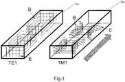
- the HPWG may be configured such that an incoming electromagnetic wave propagating in the HPGW has an electric field component of the TM1 mode in parallel to the sensing layer and an electric field component of the TE1 mode in a normal direction to the sensing layer.
- the TM1 mode is influenced by the effective refractive index and/or effective absorption coefficient of the sensing layer and catalytic layer stack.
- the TE1 mode much less or practically not influenced, may be used as a reference signal which typically remains mainly constant.
- the sensing layer comprises a metal or semi-metal, which undergoes a chemical reaction in the presence of hydrogen, typically a hydrogenation, wherein a metal-hydride-complex is formed.
- the sensing layer comprises at least one of Pd, WO 3 , Mg-M2, or Mg-M1-M2, wherein M1 and M2 are transition metals or aluminium, more preferably at least one of Ti, Ni, Zr, and Ta.
- the dielectric waveguide comprises at least one of Si, GaAs, and AlGaAs.
- the buffer layer may comprise, as a non-limiting example, SiO 2 .
- the catalytic layer may comprise at least one of Pd, Pt, and Ni, which may optionally be alloyed with at least one of gold, silver, and copper.
- the dielectric waveguide may have a closed configuration, which is chosen from at least one of: a ring, an oval, a closed spiral, and a switched-back configuration.
- a sensor configuration according to the switched-back type is, e.g., described in D.-X. Xu, A.D., A. Delpur, P. Waldron, R. McKinnon, S. Janz, J. Lapointe, G Lopinski, T. Mischki, E. Post, P. Caria and J.H. Schmid: "Folded cavity SOI microring sensors for high sensitivity and real time measurement of biomolecular binding", OPTICS EXPRESS, 2008. 16: p. 12.
- the dielectric waveguide may be straight and have the shape of a slab.
- the senor may be configured such that a ratio between the amplitudes of the TM1 electric field component and the TE1 electric field component of a propagating wave in the HPWG are dependent on the hydrogen partial pressure at the sensing layer.
- the ratio can hence be employed as a measure for the hydrogen concentration in the medium to be monitored.
- a resonance frequency in the HPWG having a ring-shape may be dependent on the refractive index of the sensing layer, and hence the resonance frequency may be taken as a measure for the hydrogen concentration in the medium to be monitored.
- the hydrogen concentration is proportional to the hydrogen partial pressure, which may thus be easily deduced from each other, as is known to the skilled person.
- the dielectric waveguide may generally have a width, in parallel to the plane of the sensing layer, from 100 nm to 4 ⁇ m, more preferably from 300 nm to 2 ⁇ m.
- the ratio between that width of the dielectric waveguide and the typically applied electromagnetic wavelength may be from about 0,24 to about 0,40.
- the HPWG may have a closed configuration, such as the shape of a ring, and a coupling waveguide is provided adjacent to a side face of the HPWG.
- a wave propagating in the coupling waveguide is at least partially coupled into the HPWG.
- the TM1 mode, or the TE1 mode, depending on the sensor configuration, of a propagating wave in the HPWG is then influenced primarily by the refractive index of the sensing layer of the HPWG. This leads to a dependency of the resonance frequency on the hydrogen partial pressure at the sensing layer, which may hence be used as an indicator for a hydrogen concentration in the medium.
- Light from a light source is coupled into the coupling waveguide, and is partially coupled into the HPWG through its sideface.
- the amount of light which is coupled into the HPWG is dependent on the condition if the resonance frequency of the HPWG ring is met by the coupled light - or on the deviation of the frequency of the light from the light source versus the resonance frequency of the ring.
- the resonance frequency of the HPWG ring changes due to a changing hydrogen level in the surrounding medium, leading to a changing refractive index of the sensing layer of the HPWG ring, this can be measured via a changing intensity of the light which passes the coupling waveguide without being coupled into the HPWG.
- a photodetector or spectrometer
- a control unit operatively coupled to the photodetector may then determine the hydrogen level in a surrounding medium based on, e.g., a look-up table with pre-stored photodetector readings versus the respective hydrogen partial pressure in the medium.
- the light source may, in a non-limiting example, be a laser diode.
- the light source may be a tunable laser, which is controlled by a control unit to continuously sweep a (narrow) frequency range around the resonance frequency of the HPWG, and wherein the photodetector detects the light intensity of the light which is not coupled into the HPWG.
- the HPWG may have the shape of a slab.
- the electromagnetic wave may be coupled into the dielectric waveguide of the slab at one of its ends, and the TM1 mode of the propagating wave is in this case influenced primarily by the absorption coefficient of the sensing layer. An attenuation of the TM1 mode in the slab may thus be used as an indicator for a hydrogen concentration in the medium.
- light from a light source is coupled into the slab.
- the light may preferably be unpolarised, or may also have a defined known polarization. While passing the sensor in form of the slab, the slab acts as a polarization selector.
- the TM1 mode is attenuated, as described, in dependency of the absorption coefficient of the sensing layer, and thus in dependency of the hydrogen partial pressure in a surrounding medium.
- a light detection device at the end of the slab opposite of the light source is configured to detect the intensity of the TM1 mode and of the TE1 mode after transmission, meaning the light detection device is suitable to detect intensities of light with different polarization.
- the light detection device may comprise a polarizing beam splitter, typically at least one of: a polarizing beam splitter cube, a Wollaston prism, a Glan-Thomson prism, a Glan-Laser prism, and any combination of the former.
- a polarizing beam splitter typically at least one of: a polarizing beam splitter cube, a Wollaston prism, a Glan-Thomson prism, a Glan-Laser prism, and any combination of the former.
- two photodetectors are provided for the two polarization components exiting the polarizing beam splitter, representing the TM1 mode and TE1 mode, respectively.
- the sensing system further comprises a control unit operatively coupled to the photodetectors.
- the ratio between the signals of the photodetectors is indicative of the hydrogen partial pressure (or concentration) in the medium surrounding the sensor (slab).
- the control unit is configured to determine/calculate the hydrogen partial pressure in the medium, based on stored values of the ratio of the intensities of the two polarization components of the TE1 mode and the TM1 mode, as measured by the two photodetectors after the polarizing beam splitter.
- the dielectric waveguide may be provided on a dielectric substrate.
- a buffer layer, and optionally the sensing layer, may be provided to extend over the side borders of the dielectric waveguide in a lateral direction.
- the dielectric waveguide is embedded between the dielectric substrate and the buffer layer.
- a hydrogen sensing system comprises a sensor according to any of the above aspects, a light source for coupling light into the sensor, and at least one light detection device.
- the hydrogen sensing system may be used in an electrical installation such as a power transformer.
- an optical gas/hydrogen sensing system in particular a control unit comprised therein operatively coupled to a light detection device, may further comprise a network interface for connecting the system to a data network, in particular a global data network.
- the data network may be a TCP/IP network such as the Internet.
- the system is operatively connected to the network interface for carrying out commands received from the data network.
- the commands may include a control command for controlling the system to carry out a task such as a measurement, a self-test, a calibration, or the like.
- the control unit is adapted for carrying out the task in response to the control command.
- the commands may include a status request.
- control unit may be adapted for sending measurement data and/or status information to the network interface, and the network interface is adapted for sending the information over the network, e.g., in response to a status request.
- the commands may include an update command including update data.
- control unit is adapted for initiating an update in response to the update command and using the update data.
- an electrical equipment with an insulation liquid wherein a hydrogen sensor of the optical hydrogen sensing system as described above is immersed in the insulation liquid, i.e. partially immersed, so that the optical sensor is at least in partial contact with the insulation liquid.
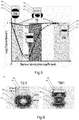
- Fig. 3 shows an exemplary hydrogen sensor 10 for detecting hydrogen in a medium 2 to be monitored according to embodiments.
- the sensor comprises a hybrid photonic-plasmonic waveguide (HPWG) 20. It comprises a dielectric waveguide 30 with a substantially rectangular cross-section, typically provided on a dielectric substrate 15.
- a buffer layer 35 is typically stacked on top of the dielectric waveguide 30.
- a sensing layer 40 is stacked on the buffer layer 35, wherein the sensing layer 40 may be metallic or semi-metallic.
- a catalytic layer 45 may be stacked on the sensing layer 40, or may in embodiments be integrated with the sensing layer 40.
- Fig. 4A a side view on the hydrogen sensor 10 of Fig.
- the sensor 10 is part of a hydrogen sensing system 100. Additionally to the sensor 10 of Fig. 3 , light from a light source 80 is coupled into one end of the dielectric waveguide 30 during operation and measured, after passing it, with a light detection device 90.
- the HPWG 20 has the elongated shape of a slab.
- a light detection device 90 at the end of the slab opposite of the light source 80 is configured to detect the intensity of the TM1 mode and of the TE1 mode after transmission, meaning the light detection device 90 is suitable to detect intensities of light with different polarization.
- the light detection device 90 may comprise a polarizing beam splitter (not shown), typically at least one of: a polarizing beam splitter cube, a Wollaston prism, a Glan-Thomson prism, a Glan-Laser prism, and any combination of the former.
- the light detection device 90 comprises two photodetectors (not shown) provided for the two polarization components exiting the polarizing beam splitter, and representing the TM1 mode and TE1 mode, respectively.
- the sensing system further comprises a control unit 91 operatively coupled to the photodetectors. The ratio between the signals of the photodetectors is indicative of the hydrogen partial pressure (or concentration) in the medium 2 surrounding the sensor (slab) 10.
- the control unit 91 is configured to determine/calculate the hydrogen partial pressure in the medium 2, based, e.g., on stored values of the ratio of the intensities of the two polarization components of the TE1 mode and the TM1 mode, as measured by the two photodetectors after the polarizing beam splitter of the light detection device 90.
- Fig. 4B shows examples of sensors according to embodiments, similar as shown in Fig. 3 , in a cross-sectional view (medium 2 not depicted for illustrational purposes).
- Variant (a) shows a (typically: Silicon-on-insulator) sensor 10 with a waveguide 30 with a top buffer layer 35 and a sensor layer 40, stacked.
- Variant (b) shows a (typically: Silicon-on-insulator) sensor 10 with a waveguide 30 with a fully covering buffer layer 35 and a top sensor layer 40.
- Variant (c) shows a (typically: Silicon-on-insulator) sensor 10 with a waveguide 30 with covering buffer layer 35 and a covering sensor layer 40.
- Variant (d) shows a sensor 10 with a waveguide 30 such as may typically be produced by ion implantation, with covering buffer layer 35 and a sensor layer 40 of variable width, which may typically be larger than the width of the waveguide.
- the buffer layer 35 and optionally the sensing layer 40 may be provided to extend over the side borders 31, 32 of the dielectric waveguide 30 in a lateral direction. This may result in the dielectric waveguide 30 being embedded between the dielectric substrate 15 and the buffer layer 35.
- an additional catalytic layer 45 and a coating layer may typically be provided similar to Fig. 3 .
- the buffer layer 35 and the substrate 15 typically have a lower refractive index than the dielectric waveguide 30 to ensure proper guiding of the light coupled into the HPWG 20.
- the sensor stack comprising the sensing layer 40 and optionally an extra dedicated catalytic layer 45, may have a higher refractive index (at the wavelength of the light used/coupled in) than the buffer layer 35. All layers typically have a higher refractive index than the environment/surroundings.
- the effective absorption coefficient of the sensor stack varies due to an external parameter present in the environment of the sensor, which is typically the hydrogen partial pressure or the partial pressure of a different gas in a surrounding medium 2.
- the TE1 mode is guided by the dielectric waveguide 30, and its intensity is relatively insensitive to the sensing layer 40 or sensing stack.
- the TE1 mode may typically be employed as a reference for the light intensity.
- the TM1 mode is mostly guided within the buffer layer 35 (buffer region), as was previously described. It is therefore in first order sensitive to a variation of the absorption coefficient of the sensing layer 40 or sensor stack.
- the attenuation per length of the HPWM 20 may be tuned by changing the thickness of the buffer layer 35 - whereby the shape of the function "transmission of the TM1 mode as a function of sensor absorption coefficient" remains unchanged.
- the TM1 mode is also in second order sensitive to the refractive index of the sensor stack. As is shown in Fig.
- the attenuation per length of HPWG 20 is always significantly lower for the transverse electric (TE1) propagation mode - and thus the transmission is higher - than for the transverse magnetic propagation mode, and this for all values of the absorption coefficient of the sensing layer/sensor stack.
- the transmission of the TE1 mode may be used in embodiments as an internal light intensity reference, and the transmission of the TM1 mode as the sensing signal.
- Fig. 5 further shows the principle of operation and sensing ranges of a HPWG sensor 10 according to embodiments.
- the transmitted light intensity is shown as a function of the optical absorption coefficient of the sensor stack (for constant refractive index), whereby the catalytic layer 45 is not shown.
- TE means transverse electric mode
- TM means transverse magnetic mode.
- both TE1 mode and TM1 mode are guided by the dielectric waveguide 30.
- the evanescent wave of the TM1 mode is situated above and below the waveguide 30, in the buffer layer 35, respectively in the substrate 15 (not shown in Fig. 5 ).
- a small part of the upper evanescent wave is within the sensing layer 40 / sensor stack, too. Therefore, a small increase of the absorption coefficient of the sensor stack absorbs the top part of the upper evanescent wave, resulting in a strong attenuation of the TM1 mode transmitted intensity.
- the TE1 mode is marginally affected, as it is situated within the dielectric waveguide 30. Its evanescent wave is left, respectively right of the dielectric waveguide, where the sensor stack according to embodiments is typically absent / not present.
- the transmission of the TM1 mode increases with increasing absorption coefficient due to the better confinement within the buffer layer 35: this is the hybrid waveguide operation, because transmission of the TE1 mode is controlled by the dielectric waveguide 30, while the TM1 transmission is controlled by the increasing metallicity of the sensor stack, thus acting partially as a metallic waveguide.
- the effective absorption coefficient of the sensing layer 40 / sensor stack varies with the hydrogen concentration - from a strong metallic character (no hydrogen content in the surroundings and in the sensing layer, high optical absorption) to a strong insulator character (fully hydrogenated sensing layer, low optical absorption).
- the sensor stack comprises a sensing layer 40, and typically, but not necessarily also a coating stack stacked on the sensing layer 40.
- the coating stack comprises the catalytic layer 45 deposited on the sensing layer 40 for catalytic splitting of the hydrogen molecules, and for fostering permeation of so-produced atomic hydrogen towards the sensing layer 40.
- Typical catalytic layers 45 comprise, as non-limiting examples, palladium, platinum or nickel, optionally further alloyed with gold, silver, and/or copper, to name a few options.
- the catalytic layer may be coated / overlayed further by other layers, such as PTFE. Their function may be to block diffusion of poisoning gases (e.g. CO, CH 4 , H 2 S) and to reduce the sensitivity to side reactions like a water formation from the hydrogen atoms in the presence of oxygen traces in the sensing layer 40 and catalytic layer 45.
- poisoning gases e.g. CO, CH 4 , H 2 S
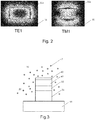
- Fig. 6 shows an exemplary sensor 10 with field distributions of the electric field for the TE1 mode and the TM1 mode. Different to other figures herein, a darker colour is representative to a stronger field strength.
- the sensor stack comprises a sensing layer 40 comprising Mg 70 Ti 30 H x , or alternatively Mg 52 Ni 20.5 Zr 27.5 H x .
- an insulation oil of a transformer may be provided as the medium 2 to be monitored.
- the dielectric waveguide operation a non-limiting example for a hydrogen sensitive material of the sensing layer 40 is proton-intercalated tungsten trioxide.
- examples of a sensing layer 40 that is sensitive to hydrogen are Mg-Ni-Zr or Mg-Ti, both coated/stacked with a catalyst layer 45 comprising Pd.
- Fig. 7 shows the waveguide 30 of a sensor 10 according to embodiments, such as shown in Fig. 3 and Fig. 4A/4B and as described above. Depicted are simulations for the decrease of the TE1 and the TM1 mode when light is coupled in the sensor 10, having the shape of a slab, from the right side.
- a sensing system employing a sensor 10 employing a sensor 10 according to embodiments as described above are the possibility to add as many protection layers on top of the sensor stack to ensure a robust sensor that is only sensitive to the desired species and resistant to adverse species and corrosion.
- the system is cost effective, as it is suitable to work at, in a non-limiting example, a telecom wavelength of 1550 nm, for which generally, low-cost components are available.
- the sensitivity is generally higher than with a Pd-based sensor, and it has a high suitability to detect hydrogen in oil of a transformer.
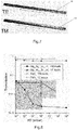
- Fig. 8 detection ranges and sensitivities for optical transmission and hydrogen pressure operation range are shown at room temperature (25°C) compared for Mg 52 Ni 20.5 Zr 27.5 Hx as a sensing layer 40 such as in embodiments, and for PdH x as a sensing layer 40.
- the transmission of the TE1 mode is hardly affected with hydrogen partial pressure for the Mg-based sensor, while the transmission of the TM1 mode is greatly varying with hydrogen partial pressure for the Mg-based sensor.
- the Mg-based sensor has generally a much better sensitivity at lower hydrogen partial pressures (left grey shaded area), whereas the Pd-based sensor shows hardly any sensitivity in this range and is only responsive at higher hydrogen partial pressures (upper right grey shaded area).
- a sensor 10a having a different shape and light path than in the previous embodiments.
- the sensor 10a is also shown as part of a sensing system 100a, which further comprises a light source 80, a light detection device 90a, and a control unit 91a.
- the HPWG 20 and thereby also the waveguide 30 have a closed configuration. That is, light in the HPWG 20 is travelling around in a ring 51, an oval, a closed spiral, or similar.
- a coupling waveguide 60 is provided on a side face of the HPWG 20.
- the ring 51 may exemplarily and non-limiting have a diameter of about 5 ⁇ m.
- alternating minima and maxima of the field along the ring 51 indicate the wave inside the sensor 10a. Further details on the structure of the waveguide 20 are provided with respect to Fig. 11 .
- closed- or ring configurations may have effective, meaning average diameters from about 2 ⁇ m to 50 ⁇ m, more particularly 3 ⁇ m to 15 ⁇ m. It is understood that these are no hard limits, as they are also dependent on the wavelength employed.
- This sensor 10a is typically employed for sensing variations of the refractive index as a ring resonator. With this closed configuration of, e.g., a ring 51 architecture, a frequency-dependent resonance of the transmitted light within the ring waveguide structure is obtained.
- a light wave propagating in the coupling waveguide 60 coming from the light source 80 being e.g. a LED, is at least partially coupled into the HPWG 20 of the sensor 10a.
- the TM1 mode, or the TE1 mode, depending on the sensor configuration, of a propagating wave in the HPWG is then influenced primarily by the refractive index of the sensing layer 40 of the HPWG. This leads to a dependency of the resonance frequency on the hydrogen partial pressure at the sensing layer, which may hence be used as an indicator for a hydrogen concentration in a surrounding medium.
- Light from the light source 80 is coupled into the coupling waveguide 60 and is partially coupled into the HPWG 20 through its sideface.
- the amount of light which is coupled into the HPWG is, inter alia, dependent on the condition, if the resonance frequency of the HPWG ring is met by the coupled light - or on the deviation of the (middle or main) frequency of the light from the light source versus the resonance frequency of the ring 51.
- the resonance frequency of the HPWG ring changes due to a changing hydrogen level in the surrounding medium, leading to a changing refractive index of the sensing layer 40 of the ring 51, this can be measured via a changing intensity of the light which passes the coupling waveguide 60 without being coupled into the HPWG 20.
- a light detection device 90a such as exemplarily a photodetector or spectrometer (both not shown in detail), is positioned at an end of the coupling waveguide 60 which is opposite to the light source 80 which emits preferably unpolarised light.
- a control unit 91a operatively coupled to the photodetector may then determine the hydrogen level in a surrounding medium based on, e.g., a look-up table with pre-stored photodetector readings versus the respective hydrogen partial pressure in the medium.
- the light source may, in a non-limiting example, be a laser diode.
- the light source may be a tunable laser, which is controlled by a control unit to continuously sweep a (narrow) frequency range around a resonance frequency (without hydrogen being present, or at a defined hydrogen partial pressure) of the HPWG 20 of the sensor 10a, and wherein the photodetector detects the light intensity of the light which is not coupled into the HPWG, by employing the readings from the light detection device 90.
- the control unit 91a may derive the current hydrogen partial pressure in the surrounding medium 2 using, e.g., a look-up-table.
- Fig. 10 changes of the resonance frequency are depicted for various changes in the refractive index of the sensing layer 40 of sensor 10a.
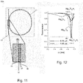
- FIG. 11 A more detailed view of a sensor 10a with closed configuration is shown in Fig. 11 .
- the coupling waveguide 60 is distanced by a small distance dx from the dielectric waveguide 30 of the HPWG 20.
- Fig. 12 the dependency of the shift of the transmission in the ring 51 from the change of the resonance wavelength is depicted. This configuration is mainly sensitive on the TE1 mode.
- Mg 70 Ti 30 may exemplarily be employed as material of the sensing layer 40.
- the shift of the resonance frequency can be tuned by the distance dx between the straight part of the coupling waveguide 60 and the ring 51 part of the resonator. If the sensing layer 40 is, in embodiments, inside of the loop formed by the ring 51 resonator as in Fig. 7 and 8 , it is sensitive to the TE-like propagation mode. Further embodiments include that the sensing layer 40 is on the outside of the dielectric waveguide 30 respectively the HPWG 20. In that case, the sensing layer 40 is predominantly sensitive to the TM1 mode.
- All sensors 10, 10a and sensing/detection systems 100, 100a may exhibit the properties and parameters as described in the aspects section further above, unless technically not feasible. It goes without saying that the embodiments described with respect to the figures may be greatly varied and modified, with some possible parameter ranges and constructional options being provided in the aspect section, and that such modifications are regarded to fall under the scope of this disclosure.
- the described sensors 10, 10a and detection systems 100, 100a have to be characterized prior to their use, or at least in prototype status, in order to obtain the data mentioned above about the relation between hydrogen partial pressure in a surrounding medium, and response of the optical sensor. As such optical sensors can be reproduced with high precision, this might only be necessary for a prototype. The obtained data then may be reused in the mass production process.
Landscapes
- Chemical & Material Sciences (AREA)
- Physics & Mathematics (AREA)
- Engineering & Computer Science (AREA)
- Health & Medical Sciences (AREA)
- Life Sciences & Earth Sciences (AREA)
- Analytical Chemistry (AREA)
- Biochemistry (AREA)
- General Health & Medical Sciences (AREA)
- General Physics & Mathematics (AREA)
- Immunology (AREA)
- Pathology (AREA)
- Medicinal Chemistry (AREA)
- Food Science & Technology (AREA)
- Combustion & Propulsion (AREA)
- Chemical Kinetics & Catalysis (AREA)
- Plasma & Fusion (AREA)
- Investigating Or Analysing Materials By Optical Means (AREA)
Priority Applications (1)
| Application Number | Priority Date | Filing Date | Title |
|---|---|---|---|
| EP17172215.0A EP3407062A1 (fr) | 2017-05-22 | 2017-05-22 | Système de détection d'hydrogène à guide d'ondes diélectrique |
Applications Claiming Priority (1)
| Application Number | Priority Date | Filing Date | Title |
|---|---|---|---|
| EP17172215.0A EP3407062A1 (fr) | 2017-05-22 | 2017-05-22 | Système de détection d'hydrogène à guide d'ondes diélectrique |
Publications (1)
| Publication Number | Publication Date |
|---|---|
| EP3407062A1 true EP3407062A1 (fr) | 2018-11-28 |
Family
ID=58765734
Family Applications (1)
| Application Number | Title | Priority Date | Filing Date |
|---|---|---|---|
| EP17172215.0A Withdrawn EP3407062A1 (fr) | 2017-05-22 | 2017-05-22 | Système de détection d'hydrogène à guide d'ondes diélectrique |
Country Status (1)
| Country | Link |
|---|---|
| EP (1) | EP3407062A1 (fr) |
Cited By (2)
| Publication number | Priority date | Publication date | Assignee | Title |
|---|---|---|---|---|
| CN112240903A (zh) * | 2019-07-19 | 2021-01-19 | 深圳大学 | 氢气传感器芯体及其制备方法 |
| WO2023163999A1 (fr) * | 2022-02-22 | 2023-08-31 | Giner, Inc. | Capteur d'hydrogène gazeux et procédés et systèmes l'utilisant |
Citations (4)
| Publication number | Priority date | Publication date | Assignee | Title |
|---|---|---|---|---|
| WO2007049965A1 (fr) | 2005-10-28 | 2007-05-03 | Advanced Chemical Technologies For Sustainability | Dispositif de commutation optique |
| US20080158563A1 (en) * | 2006-08-21 | 2008-07-03 | Pierre Simon Joseph Berini | Sensors |
| EP2778660A1 (fr) | 2013-03-15 | 2014-09-17 | ABB Research Ltd. | Ensemble capteur et procédé pour détecter un état de statut d'équipement électrique |
| WO2016026803A1 (fr) | 2014-08-19 | 2016-02-25 | Abb Technology Ag | Capteur d'hydrogène avec couche de protection |
-
2017
- 2017-05-22 EP EP17172215.0A patent/EP3407062A1/fr not_active Withdrawn
Patent Citations (4)
| Publication number | Priority date | Publication date | Assignee | Title |
|---|---|---|---|---|
| WO2007049965A1 (fr) | 2005-10-28 | 2007-05-03 | Advanced Chemical Technologies For Sustainability | Dispositif de commutation optique |
| US20080158563A1 (en) * | 2006-08-21 | 2008-07-03 | Pierre Simon Joseph Berini | Sensors |
| EP2778660A1 (fr) | 2013-03-15 | 2014-09-17 | ABB Research Ltd. | Ensemble capteur et procédé pour détecter un état de statut d'équipement électrique |
| WO2016026803A1 (fr) | 2014-08-19 | 2016-02-25 | Abb Technology Ag | Capteur d'hydrogène avec couche de protection |
Non-Patent Citations (5)
| Title |
|---|
| AYA O ZAKI ET AL: "Integrated optical sensor using hybrid plasmonics for lab on chip applications", JOURNAL OF OPTICS, INSTITUTE OF PHYSICS PUBLISHING, BRISTOL GB, vol. 18, no. 8, 7 July 2016 (2016-07-07), pages 85803, XP020307308, ISSN: 2040-8986, [retrieved on 20160707], DOI: 10.1088/2040-8978/18/8/085803 * |
| CÉDRIC PERROTTON ET AL: "A reliable, sensitive and fast optical fiber hydrogen sensor based on surface plasmon resonance References and links / OPTICS EXPRESS 382", OPT. EXPRESS OPT. LASERS ENG. MEAS. SCI. TECHNOL. IEEE PHOTON. TECHNOL. LETT. J. OPT. A, PURE APPL. OPT. OPT. LASERS ENG. APPL. SURF. SCI. MEAS. SCI. TECHNOL. OPT. LETT. NANO LETT. NANO LETT. NANO LETT. APPL. PHYS. LETT. SENS. ACT. B SENS. ACTUATORS, 1 January 2005 (2005-01-01), pages 5087 - 5092, XP055418510, Retrieved from the Internet <URL:https://www.osapublishing.org/DirectPDFAccess/0FD3E1B4-9143-3D81-6550CECEE0C941CD_247976/oe-21-1-382.pdf?da=1&id=247976&seq=0&mobile=no> * |
| D.-X. XU, A.D.; A. DELAGE; P. WALDRON; R. MCKINNON; S. JANZ; J. LAPOINTE; G. LOPINSKI; T. MISCHKI; E. POST; P. CHEBEN: "Folded cavity SOI microring sensors for high sensitivity and real time measurement of biomolecular binding", OPTICS EXPRESS, vol. 16, 2008, pages 12 |
| MERCEDES VICTORIA ET AL: "Amorphous Metal-Hydrides for Optical Hydrogen Sensing: The Effect of Adding Glassy Ni-Zr to Mg-Ni-H", ACS SENSORS, vol. 1, no. 3, 25 March 2016 (2016-03-25), pages 222 - 226, XP055418744, ISSN: 2379-3694, DOI: 10.1021/acssensors.5b00265 * |
| YA SHA YI ET AL: "Plasmonic hydrogen sensor based on integrated microring resonator", OPTICAL ENGINEERING., vol. 56, no. 12, 23 March 2017 (2017-03-23), BELLINGHAM, pages 121904, XP055419251, ISSN: 0091-3286, DOI: 10.1117/1.OE.56.12.121904 * |
Cited By (2)
| Publication number | Priority date | Publication date | Assignee | Title |
|---|---|---|---|---|
| CN112240903A (zh) * | 2019-07-19 | 2021-01-19 | 深圳大学 | 氢气传感器芯体及其制备方法 |
| WO2023163999A1 (fr) * | 2022-02-22 | 2023-08-31 | Giner, Inc. | Capteur d'hydrogène gazeux et procédés et systèmes l'utilisant |
Similar Documents
| Publication | Publication Date | Title |
|---|---|---|
| Chen et al. | Review of optical fibre sensors for electrical equipment characteristic state parameters detection | |
| US8547553B2 (en) | Fiber optic hydrogen purity sensor and system | |
| Hosoki et al. | A surface plasmon resonance hydrogen sensor using Au/Ta2O5/Pd multi-layers on hetero-core optical fiber structures | |
| Chen et al. | Wide range refractive index measurement using a multi-angle tilted fiber Bragg grating | |
| JP6344789B2 (ja) | 水素センサ、および、それを用いた検出装置 | |
| JP2012032398A (ja) | 光ファイバ二酸化炭素純度センサ・パッケージ及びシステム | |
| US7085452B1 (en) | Optical devices having WGM cavity coupled to side-polished port | |
| Liu et al. | High refractive index liquid level measurement via coreless multimode fiber | |
| US7060964B1 (en) | Reflection-mode fiber sensing devices | |
| Coelho et al. | Multiplexing of surface plasmon resonance sensing devices on etched single-mode fiber | |
| US9377451B2 (en) | Sensor assembly and method for sensing status condition of electrical equipment | |
| US10684229B2 (en) | Optical sensing system for determining hydrogen partial pressure | |
| EP3407062A1 (fr) | Système de détection d'hydrogène à guide d'ondes diélectrique | |
| EP1372006A1 (fr) | Dispositif comprenant un réseau de diffraction dans un guide d'onde optique et capteurs l'utilisant | |
| Dyshlyuk et al. | Numerical and experimental investigation of surface plasmon resonance excitation using whispering gallery modes in bent metal-clad single-mode optical fiber | |
| EP3399299A1 (fr) | Capteur de gaz utilisant la polarisation, système et procédé de détection de gaz l'utilisant | |
| US7087887B1 (en) | Optical multiphase flow sensor | |
| Ecke et al. | Chemical Bragg grating sensor network based on side-polished optical fiber | |
| Falate et al. | Petroleum hydrocarbon detection with long period gratings | |
| US20260104360A1 (en) | Detecting hydrogen by measuring amplified hydride crystallographic changes | |
| Srivastava et al. | Novel Long Period Gratings in Channeled Optical Fibers | |
| Wang et al. | In Situ Detection of Transformer Oil-dissolved Trace Hydrogen using a Composite Membrane-modified Fiber-optic Fabry-Pérot Probe | |
| Iadicicco et al. | Thinned fiber Bragg gratings for sensing applications | |
| Zhao et al. | Dual-parameter Cu2+ concentration and temperature sensor based on a wavelength-tunable fiber laser incorporating SNMNMS interferometer and FBG | |
| Falate et al. | Long period grating application for fuel quality control |
Legal Events
| Date | Code | Title | Description |
|---|---|---|---|
| PUAI | Public reference made under article 153(3) epc to a published international application that has entered the european phase |
Free format text: ORIGINAL CODE: 0009012 |
|
| STAA | Information on the status of an ep patent application or granted ep patent |
Free format text: STATUS: THE APPLICATION HAS BEEN PUBLISHED |
|
| AK | Designated contracting states |
Kind code of ref document: A1 Designated state(s): AL AT BE BG CH CY CZ DE DK EE ES FI FR GB GR HR HU IE IS IT LI LT LU LV MC MK MT NL NO PL PT RO RS SE SI SK SM TR |
|
| AX | Request for extension of the european patent |
Extension state: BA ME |
|
| STAA | Information on the status of an ep patent application or granted ep patent |
Free format text: STATUS: THE APPLICATION IS DEEMED TO BE WITHDRAWN |
|
| 18D | Application deemed to be withdrawn |
Effective date: 20190529 |