EP3407144A2 - Uhr, die eine verriegelungsvorrichtung für eine drucktaste umfasst - Google Patents
Uhr, die eine verriegelungsvorrichtung für eine drucktaste umfasst Download PDFInfo
- Publication number
- EP3407144A2 EP3407144A2 EP18172258.8A EP18172258A EP3407144A2 EP 3407144 A2 EP3407144 A2 EP 3407144A2 EP 18172258 A EP18172258 A EP 18172258A EP 3407144 A2 EP3407144 A2 EP 3407144A2
- Authority
- EP
- European Patent Office
- Prior art keywords
- locking
- pusher
- axis
- timepiece according
- locking member
- Prior art date
- Legal status (The legal status is an assumption and is not a legal conclusion. Google has not performed a legal analysis and makes no representation as to the accuracy of the status listed.)
- Granted
Links
Images

Classifications
-
- G—PHYSICS
- G04—HOROLOGY
- G04B—MECHANICALLY-DRIVEN CLOCKS OR WATCHES; MECHANICAL PARTS OF CLOCKS OR WATCHES IN GENERAL; TIME PIECES USING THE POSITION OF THE SUN, MOON OR STARS
- G04B37/00—Cases
- G04B37/0091—Cases for clock parts, e.g. for the escapement or the electric motor
-
- G—PHYSICS
- G04—HOROLOGY
- G04B—MECHANICALLY-DRIVEN CLOCKS OR WATCHES; MECHANICAL PARTS OF CLOCKS OR WATCHES IN GENERAL; TIME PIECES USING THE POSITION OF THE SUN, MOON OR STARS
- G04B3/00—Normal winding of clockworks by hand or mechanically; Winding up several mainsprings or driving weights simultaneously
- G04B3/04—Rigidly-mounted keys, knobs or crowns
- G04B3/043—Locking of the operating element, also by mounting in a concealed place
-
- G—PHYSICS
- G04—HOROLOGY
- G04B—MECHANICALLY-DRIVEN CLOCKS OR WATCHES; MECHANICAL PARTS OF CLOCKS OR WATCHES IN GENERAL; TIME PIECES USING THE POSITION OF THE SUN, MOON OR STARS
- G04B19/00—Indicating the time by visual means
- G04B19/06—Dials
- G04B19/18—Graduations on the crystal or glass, on the bezel, or on the rim
-
- G—PHYSICS
- G04—HOROLOGY
- G04B—MECHANICALLY-DRIVEN CLOCKS OR WATCHES; MECHANICAL PARTS OF CLOCKS OR WATCHES IN GENERAL; TIME PIECES USING THE POSITION OF THE SUN, MOON OR STARS
- G04B19/00—Indicating the time by visual means
- G04B19/28—Adjustable guide marks or pointers for indicating determined points of time
- G04B19/283—Adjustable guide marks or pointers for indicating determined points of time on rotatable rings, i.e. bezel
-
- G—PHYSICS
- G04—HOROLOGY
- G04B—MECHANICALLY-DRIVEN CLOCKS OR WATCHES; MECHANICAL PARTS OF CLOCKS OR WATCHES IN GENERAL; TIME PIECES USING THE POSITION OF THE SUN, MOON OR STARS
- G04B3/00—Normal winding of clockworks by hand or mechanically; Winding up several mainsprings or driving weights simultaneously
- G04B3/001—Normal winding of clockworks by hand or mechanically; Winding up several mainsprings or driving weights simultaneously by push button
-
- G—PHYSICS
- G04—HOROLOGY
- G04B—MECHANICALLY-DRIVEN CLOCKS OR WATCHES; MECHANICAL PARTS OF CLOCKS OR WATCHES IN GENERAL; TIME PIECES USING THE POSITION OF THE SUN, MOON OR STARS
- G04B3/00—Normal winding of clockworks by hand or mechanically; Winding up several mainsprings or driving weights simultaneously
- G04B3/04—Rigidly-mounted keys, knobs or crowns
- G04B3/045—Storing the operating element, also bringing it out of storage
-
- G—PHYSICS
- G04—HOROLOGY
- G04B—MECHANICALLY-DRIVEN CLOCKS OR WATCHES; MECHANICAL PARTS OF CLOCKS OR WATCHES IN GENERAL; TIME PIECES USING THE POSITION OF THE SUN, MOON OR STARS
- G04B3/00—Normal winding of clockworks by hand or mechanically; Winding up several mainsprings or driving weights simultaneously
- G04B3/04—Rigidly-mounted keys, knobs or crowns
- G04B3/046—Operation by rotation and axial movement with extra function of axial shift of operating element, e.g. crown combined with push button
-
- G—PHYSICS
- G04—HOROLOGY
- G04B—MECHANICALLY-DRIVEN CLOCKS OR WATCHES; MECHANICAL PARTS OF CLOCKS OR WATCHES IN GENERAL; TIME PIECES USING THE POSITION OF THE SUN, MOON OR STARS
- G04B3/00—Normal winding of clockworks by hand or mechanically; Winding up several mainsprings or driving weights simultaneously
- G04B3/04—Rigidly-mounted keys, knobs or crowns
- G04B3/048—Operation exclusively by axial movement of a push-button, e.g. for chronographs
-
- G—PHYSICS
- G04—HOROLOGY
- G04B—MECHANICALLY-DRIVEN CLOCKS OR WATCHES; MECHANICAL PARTS OF CLOCKS OR WATCHES IN GENERAL; TIME PIECES USING THE POSITION OF THE SUN, MOON OR STARS
- G04B37/00—Cases
- G04B37/0008—Cases for pocket watches and wrist watches
-
- G—PHYSICS
- G04—HOROLOGY
- G04B—MECHANICALLY-DRIVEN CLOCKS OR WATCHES; MECHANICAL PARTS OF CLOCKS OR WATCHES IN GENERAL; TIME PIECES USING THE POSITION OF THE SUN, MOON OR STARS
- G04B37/00—Cases
- G04B37/08—Hermetic sealing of openings, joints, passages or slits
- G04B37/10—Hermetic sealing of openings, joints, passages or slits of winding stems
- G04B37/106—Hermetic sealing of openings, joints, passages or slits of winding stems of push buttons
-
- G—PHYSICS
- G04—HOROLOGY
- G04B—MECHANICALLY-DRIVEN CLOCKS OR WATCHES; MECHANICAL PARTS OF CLOCKS OR WATCHES IN GENERAL; TIME PIECES USING THE POSITION OF THE SUN, MOON OR STARS
- G04B47/00—Time-pieces combined with other articles which do not interfere with the running or the time-keeping of the time-piece
- G04B47/06—Time-pieces combined with other articles which do not interfere with the running or the time-keeping of the time-piece with attached measuring instruments, e.g. pedometer, barometer, thermometer or compass
- G04B47/066—Time-pieces combined with other articles which do not interfere with the running or the time-keeping of the time-piece with attached measuring instruments, e.g. pedometer, barometer, thermometer or compass with a pressure sensor
-
- G—PHYSICS
- G04—HOROLOGY
- G04F—TIME-INTERVAL MEASURING
- G04F7/00—Apparatus for measuring unknown time intervals by non-electric means
- G04F7/04—Apparatus for measuring unknown time intervals by non-electric means using a mechanical oscillator
- G04F7/08—Watches or clocks with stop devices, e.g. chronograph
- G04F7/0866—Special arrangements
Definitions
- the present invention relates to the field of watchmaking. It relates more particularly to a timepiece comprising a locking device for a pusher operable by a user of the timepiece, including a push button.
- timepieces comprising a locking device that makes it possible to disable a push button.
- These devices are intended to prevent the accidental actuation of the push button or, for diving watches, to avoid actuation of the push button under the effect of external pressure.
- the demand CH678138 proposes a screwed pusher which can be immobilized by a threaded ring, coaxial with the pusher.
- the threaded ring is aimed at the pendant of the pusher and can bear under the head of the pusher to prevent its actuation.
- Requirement US9105413 describes a variant of this device.
- Requirement CH707595 has a lockable watch pusher with a rotary ring coaxial with the pusher and whose rotation causes the axial displacement of a socket capable of bearing under the head of the pusher.
- the push buttons provided with such a locking device have a massive appearance.
- the pitch of screw used to transform the rotational movement in translation must be small enough so that the transformation is not reversible accidentally, that is to say that the friction is sufficient to oppose a inadvertent unscrewing.
- a significant handling time due to the large number of rotations of the control ring, is necessary to switch the device between its locked and unlocked states.
- the locking operation can be particularly tedious because it must be performed successively for each of the pushers.
- Pusher locking devices are also known which partially provide a solution to the problem mentioned above.
- the document US 2010/014233 proposes to block the actuation of a pusher by a movable frame vertically, perpendicular to the axis of actuation of the pusher.
- This frame defines an upper stop for the pusher, which is placed behind the pusher head according to the position of a rotating bezel which serves as control member of the locking device.
- the frame and therefore the stop are arranged under the rotating bezel to be able to be actuated directly by a surface bottom of this rotating bezel.
- This embodiment has a first disadvantage in that the rear portion of the pusher head must be inserted into the watch case when the pusher is in its rest position (pusher not actuated).
- a second disadvantage comes from the fact that the pusher is locked by a small stop acting only against the upper part of the pusher head.
- a third drawback arises from the fact that the locking device is bulky, in particular the frame which moves vertically in the middle part, which must have an obvious for this purpose. In addition, the vertical movement of the frame requires a relatively high housing to allow this movement inside this housing.
- Document is also known EP 1 582 945 , figures 7.8 and 11, a device for locking a pusher in which a tube and a piston passing through this tube are integral with the head of the pusher, the tube being fixed to this head and the piston being arranged movable in the tube between two vertical positions, that is to say between two positions along an axis perpendicular to the axis of actuation of the pusher.
- a rotating bezel has a groove in its lower surface, one end of the piston being housed in this groove. This groove has a portion (45) with a depth which varies so as to allow actuation of the piston in the tube between two extreme positions which respectively define a locking position and an unlocking position of the pusher.
- the present invention aims to overcome the various disadvantages of the prior art by providing a timepiece provided with a locking device of at least one pusher which is less bulky, more discreet and easier to use.
- the present invention relates to a timepiece comprising a housing, a pusher mounted in a middle of the housing and a locking device adapted to lock the pusher, this pusher being arranged to be able to undergo a translation along an axis actuation of the pusher by a user.
- the locking device comprises a locking member and a control member arranged to control the movement of the locking member between a locking position and an unlocking position in which the pusher is respectively locked and free in translation.
- the control member extends in a general plane parallel to said actuating axis and is arranged movable in this general plane between a first position and a corresponding second position, for the locking member driven by the control member, respectively at the locking and unlocking positions.
- the locking member is arranged movable in translation along the axis of actuation and can be displaced by the control member along the axis of actuation between the position locking, where it forms an axial stop for the pusher, and the unlocking position set back from the locking position.
- the control member comprises means for driving the locking member along the axis of actuation.
- the timepiece comprises a telescope and the control member is formed by an intermediate ring mounted between the caseband and the bezel, this ring being able to rotate about an axis substantially perpendicular to the case. actuation axis.
- the timepiece comprises a rotating bezel forming the control member.
- the locking member is a cylindrical sleeve surrounding the pusher and arranged movable along the axis of actuation of the pusher.
- the locking member is a slider arranged movable along the axis of actuation of the pusher.
- the pusher comprises a head and the locking member is adapted to be positioned, to lock it, at a short distance from this head or against it.
- control member has a radial positioning cam of the locking member cooperating with a follower means that comprises the locking member.
- the timepiece comprises an elastic return means tending to maintain the follower means in contact with the cam.
- the cam is formed by a groove and the follower means is a lug inserted in this groove.
- the cam is formed by a rib / rail protruding under the control member and the follower means is a notch machined in the locking member.
- the locking device comprises a visual means facilitating the recognition of the position of the locking member.
- the locking device comprises a positioning means provided for holding in place the control member in its first and second positions which thus define two stable positions.
- each of the first and second positions of the control member is provided by a hard point, for example formed of a ball mounted on an elastic element.
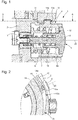
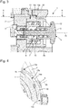
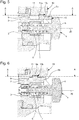
- the figures show partial sectional views of a timepiece revealing a pushbutton arranged in the middle part 2 of the housing 1 and its locking device.
- the push button forms in particular a control member of a chronograph mechanism.
- This pushbutton is composed of a pendant 3, screwed into a tapping that includes the middle part 2, and a pusher 4 extending partially outside the timepiece to be operable by a user .
- the pusher 4 comprises a head 5 and a rod 6 slidable in an opening that has the pendant 3 along an axis of actuation 20 through the middle parallel to the general plane of the housing.
- a first spring 7 tends to maintain the pusher 4 in distal position with reference to the middle part 2 (as shown in all the figures).
- the timepiece comprises a locking device comprising a locking member 8 movable in translation along the axis of actuation 20.
- the locking member 8 is formed by a cylindrical sleeve 8a surrounding the pusher 4, the sleeve having an inner shoulder defining a stop 12 for the head 5 of the pusher at least when the locking device is in its locking position.
- the locking device also comprises a control member 10 rotatably mounted with reference to the middle part 2, about an axis perpendicular to the general plane of the housing 1, and therefore perpendicular to the actuating axis 20.
- the organ control device extends in the general plane of the housing which is substantially parallel to the axis of actuation and is arranged movable in this general plane between a first position and a second position respectively corresponding to the locking and unlocking positions of the device locking.
- the control member 10 extends at least partially outside the housing so as to be easily operable by a user.
- the control member is a rotating ring 10 mounted between the middle part 2 and a bezel 11 that comprises the housing 1.
- the locking member 8 can be moved between a locking position shown in FIGS. Figures 1 and 2 and an unlock position shown at Figures 3 and 4 .
- a stop 12 of the locking member 8 is placed directly under the head 5 of the pusher 4 to substantially block the pusher 4 in translation and thus prevent its actuation to perform the function associated with this button.
- the unlocking position the locking member has been translated along the axis of actuation so as to release the pusher 4 in translation and to make it operational.
- control member 10 which is kinematically connected to the locking member 8.
- control member 10 comprises driving means cooperating with a follower means that comprises the locking member 8.
- the drive means are formed by a cam 13a and an elastic return means 15 while the follower means is formed by a lug 14a engaging the cam 13a and acting as follower cam.
- the elastic return means 15 (In particular a helical spring) makes it possible to maintain the lug 14a in contact with the cam 13a in the two actuating directions of the control member.
- the cam 13a is defined by a lateral surface of an internal recess of the rotating ring 10 whose profile has a monotonic radial variation between two angular positions respectively defining a first position and a second position corresponding to the locking positions. and unlocking.
- the locking device preferably comprises a positioning means arranged to hold the control member in place in the first and second positions mentioned above.
- the control member may be pivotally mounted with greasy friction, which may be sufficient to ensure its maintenance in said first and second positions.
- the positioning means shown in the figures is firstly formed by the slope of the cam 13a substantially zero at its two ends 13c which respectively define said first and second positions. The slope of the cam is considered in a circular reference, so that a zero slope corresponds to a circular path.
- the positioning can also be achieved or reinforced by the fact that the lug 14a is held radially in its two extreme radial positions, corresponding to the first and second positions, on the one hand by an inner tongue 16 formed in the rotating ring 10 and on the other hand by a bearing surface defined by the middle part 2.
- the slope of the cam in the central zone causes a relatively rapid displacement of the locking member in response to a small angular displacement of the control member, while that the substantially zero slope at the ends 13c of the cam prevents the transmission of a torque of the follower member to the control member.
- a rotation of about thirty degrees of rotating ring makes it possible to move the locking member in both directions between its locking and unlocking positions.
- the positioning means of the control member comprises hard points that must be exceeded just before reaching said first and second positions and therefore either the locking position or the unlocking position. This makes it possible to further secure the two functional positions of the control member.
- the passage of a hard point further provides a tactile indication of the locking or unlocking to the user.
- the locking member is a slider 8b slidable in the direction of the axis of actuation of the pusher in a radial slide 9 that includes the middle part.
- the slide 9 may have a dovetail shape or any other suitable profile.
- control member 10 is directly formed by a rotating bezel 11 that includes or supports the housing.
- the cam is formed by a groove 13b at least partially housing the lug 14a and having substantially the width of the diameter of the lug.
- This configuration corresponds to a desmodromic control for which the elastic return means of the drive means of the locking member can be eliminated in order to limit the size of the locking device. It can however be interesting to keep a low elastic return means in this case to make up the play between the parts and eliminate small parasitic translations of the locking member.
- the cam may equally well be a protruding rib and the follower means a notch machined in the locking member and receiving the rib, the sliding of the rib in the notch causing the radial displacement of the locking member.
- the locking device may also include a visual means facilitating recognition of the position of the locking member.
- This visual means typically a marking, can be located on the control member or directly on the locking member.
- the locking member is concealed in the unlocking position while it is visible in the locking position.
- the visibility of the locking member which can be enhanced by a bright color, is in this case the visual means that allows to know his position.
- control member 10 has a plurality of grooves 13b, respectively several cams 13a to lock simultaneously several pushers.
- the various proposed solutions allow for locking devices for one or more pushers that are easier and faster to use by locking with a single gesture.
- the fact that the locking member can be fully retracted into the middle part makes the locking device discrete.
- the actuation of a conventional pusher is not made less easy by the presence of the locking device when the latter is placed in the unlocking position.
- the fact of deporting the control member at the level of the telescope makes it possible to almost not increase the size of the pushers with the arrangement of the locking device according to the invention, which allows to keep a classic appearance to the watch case that may seem externally almost identical to a corresponding case without such a locking device.
Landscapes
- Physics & Mathematics (AREA)
- General Physics & Mathematics (AREA)
- Electric Clocks (AREA)
- Lock And Its Accessories (AREA)
Applications Claiming Priority (1)
| Application Number | Priority Date | Filing Date | Title |
|---|---|---|---|
| EP17172883 | 2017-05-24 |
Publications (3)
| Publication Number | Publication Date |
|---|---|
| EP3407144A2 true EP3407144A2 (de) | 2018-11-28 |
| EP3407144A3 EP3407144A3 (de) | 2019-01-23 |
| EP3407144B1 EP3407144B1 (de) | 2021-06-30 |
Family
ID=58772795
Family Applications (1)
| Application Number | Title | Priority Date | Filing Date |
|---|---|---|---|
| EP18172258.8A Active EP3407144B1 (de) | 2017-05-24 | 2018-05-15 | Uhr, die eine verriegelungsvorrichtung für eine drucktaste umfasst |
Country Status (6)
| Country | Link |
|---|---|
| US (1) | US10725429B2 (de) |
| EP (1) | EP3407144B1 (de) |
| JP (1) | JP6537672B2 (de) |
| KR (1) | KR102071790B1 (de) |
| CN (1) | CN108958001B (de) |
| CH (1) | CH713834A2 (de) |
Cited By (4)
| Publication number | Priority date | Publication date | Assignee | Title |
|---|---|---|---|---|
| EP3825777A1 (de) * | 2019-11-21 | 2021-05-26 | Meco S.A. | Korrekturvorrichtung einer armbanduhr und armbanduhrgehäuse |
| EP4047423A1 (de) * | 2021-02-17 | 2022-08-24 | Omega SA | Armbanduhr, die mit einer verriegelungsvorrichtung eines externen steuerorgans ausgestattet ist |
| US11809139B2 (en) | 2018-04-20 | 2023-11-07 | Rolex Sa | Locking system for a control element of a timepiece |
| EP3663866B1 (de) * | 2018-11-09 | 2025-11-26 | Omega SA | Uhr, die eine betätigungsvorrichtung einer krone oder eines ventils umfasst |
Families Citing this family (14)
| Publication number | Priority date | Publication date | Assignee | Title |
|---|---|---|---|---|
| EP3451071B1 (de) * | 2017-09-01 | 2020-07-22 | Omega SA | Vorrichtung mit drucktaste für uhr |
| JP7417852B2 (ja) | 2018-10-19 | 2024-01-19 | 三菱マテリアル株式会社 | 被覆電線の処理方法 |
| EP3650951B1 (de) * | 2018-11-09 | 2021-06-16 | Omega SA | Uhr, die eine verriegelungsvorrichtung eines ventils oder einer krone umfasst |
| EP3742235B1 (de) * | 2019-05-23 | 2022-01-26 | Meco S.A. | Druckknopfsystem und dieses umfassende uhr |
| EP3754434A1 (de) * | 2019-06-17 | 2020-12-23 | Omega SA | Uhr, insbesondere taschenuhr, die mit mindestens einem deckel ausgestattet ist |
| EP3770693B1 (de) * | 2019-07-23 | 2022-08-31 | Omega SA | Anschlagmechanismus für uhrenkäfig mit anschlagrad |
| TWI726555B (zh) * | 2019-12-27 | 2021-05-01 | 致茂電子股份有限公司 | 下壓頭鎖定機構、及具備該機構之電子元件檢測設備 |
| EP3923087A1 (de) * | 2020-06-10 | 2021-12-15 | Meco S.A. | Abdichtungsvorrichtung |
| EP4006647B1 (de) * | 2020-11-25 | 2023-05-10 | Meco S.A. | Drückerkrone für uhr |
| EP4092490B1 (de) * | 2021-05-19 | 2024-12-25 | Meco SA | Steuervorrichtung für ein uhrwerk mit taktiler rückmeldung und uhrwerk, insbesondere armbanduhr, mit einer solchen vorrichtung |
| EP4194967B1 (de) * | 2021-12-07 | 2025-05-28 | The Swatch Group Research and Development Ltd | Vorrichtung zur befestigung eines bodens auf einem gehäuserahmen einer uhr |
| FI4231100T3 (fi) * | 2022-02-22 | 2024-11-29 | Eta Sa Mft Horlogere Suisse | Kellon ohjauslaite |
| EP4455796A1 (de) * | 2023-04-27 | 2024-10-30 | Patek Philippe SA Genève | Uhr mit positionsauswahlvorrichtung |
| EP4567525A1 (de) * | 2023-12-07 | 2025-06-11 | Harry Winston SA | Verriegelungsvorrichtung für einen stössel eines armbanduhrgehäuses |
Citations (5)
| Publication number | Priority date | Publication date | Assignee | Title |
|---|---|---|---|---|
| CH678138A5 (en) | 1989-04-13 | 1991-08-15 | Screw operated watch pushbutton lock - prevents accidental resetting of watch functions by locking button in non-operating position | |
| EP1582945A2 (de) | 2004-03-31 | 2005-10-05 | Alfred Dunhill Limited | Uhr mit Druckknöpfen |
| US20100014233A1 (en) | 2008-07-16 | 2010-01-21 | International Business Machines Corporation | Apparatus for display movement of a laptop computer |
| CH707595A2 (fr) | 2013-02-13 | 2014-08-15 | Roland Prétat | Poussoir de montre chronographe vissable et blocable à l'aide d'un anneau rotatif et d'une douille télescopique se déplaçant axialement. |
| US9105413B2 (en) | 2012-02-07 | 2015-08-11 | Seiko Instruments Inc. | Portable apparatus and portable timepiece |
Family Cites Families (21)
| Publication number | Priority date | Publication date | Assignee | Title |
|---|---|---|---|---|
| CH1152567A4 (de) * | 1967-08-16 | 1969-09-15 | ||
| CH304969A4 (de) | 1969-02-28 | 1970-10-15 | ||
| KR800000142B1 (ko) * | 1974-01-01 | 1980-03-08 | 핫도리 이찌도오 | 손목시계 용두(龍頭)의 구조 |
| CH685901B5 (fr) * | 1993-11-25 | 1996-05-15 | Smh Management Services Ag | Couronne-poussoir pour piece d'horlogerie. |
| US5742565A (en) * | 1996-05-21 | 1998-04-21 | Timex Corporation | Crown setting device for a timepiece |
| KR19990088020A (ko) * | 1998-05-13 | 1999-12-27 | 에따 쏘시에떼 아노님 파브리끄 데보슈 | 시계,특히크로노그래프의누름단추 |
| JP5025855B2 (ja) * | 2001-04-27 | 2012-09-12 | セイコーインスツル株式会社 | 腕携帯用機器 |
| JP4506218B2 (ja) * | 2003-03-31 | 2010-07-21 | セイコーエプソン株式会社 | ボタン構造、およびこれを備えた携帯機器 |
| ATE400005T1 (de) * | 2006-04-25 | 2008-07-15 | Swatch Group Man Serv Ag | Uhr mit einem drehbaren teil |
| JP4745930B2 (ja) * | 2006-09-19 | 2011-08-10 | セイコーインスツル株式会社 | 携帯時計 |
| JP4874066B2 (ja) * | 2006-11-22 | 2012-02-08 | セイコーインスツル株式会社 | 時計 |
| EP1939699B1 (de) * | 2006-12-29 | 2012-05-30 | Montres Breguet S.A. | Multifunktionsvorrichtung zur koaxialen Korrektur |
| JP4937013B2 (ja) * | 2007-06-28 | 2012-05-23 | セイコーインスツル株式会社 | 携帯時計が備える竜頭の製造方法 |
| DE602007004674D1 (de) * | 2007-11-08 | 2010-03-25 | Meco Sa | Krone für Uhr |
| JP5315024B2 (ja) | 2008-11-26 | 2013-10-16 | セイコーインスツル株式会社 | 携帯機器及び携帯時計 |
| IT1392945B1 (it) * | 2009-02-23 | 2012-04-02 | Romano | Pulsanti stagni per orologi cronografi |
| CH700535A1 (fr) | 2009-03-11 | 2010-09-15 | Francoise Schuerch | Montre-bracelet comportant une lunette rotative. |
| CH705090A2 (fr) * | 2011-06-08 | 2012-12-14 | Omega Sa | Dispositif pour l'orientation d'une couronne vissée d'une pièce d'horlogerie. |
| US8783944B2 (en) * | 2011-07-22 | 2014-07-22 | Casio Computer Co., Ltd. | Switch device and wristwatch |
| JP5440886B2 (ja) * | 2011-12-19 | 2014-03-12 | カシオ計算機株式会社 | スイッチ装置及び腕時計 |
| US10018963B2 (en) * | 2014-03-26 | 2018-07-10 | The Swatch Group Management Services Ag | Control system for a timepiece |
-
2018
- 2018-05-07 US US15/972,280 patent/US10725429B2/en active Active
- 2018-05-14 CH CH00593/18A patent/CH713834A2/fr not_active Application Discontinuation
- 2018-05-15 EP EP18172258.8A patent/EP3407144B1/de active Active
- 2018-05-21 KR KR1020180057816A patent/KR102071790B1/ko active Active
- 2018-05-21 JP JP2018096929A patent/JP6537672B2/ja active Active
- 2018-05-22 CN CN201810493836.8A patent/CN108958001B/zh active Active
Patent Citations (5)
| Publication number | Priority date | Publication date | Assignee | Title |
|---|---|---|---|---|
| CH678138A5 (en) | 1989-04-13 | 1991-08-15 | Screw operated watch pushbutton lock - prevents accidental resetting of watch functions by locking button in non-operating position | |
| EP1582945A2 (de) | 2004-03-31 | 2005-10-05 | Alfred Dunhill Limited | Uhr mit Druckknöpfen |
| US20100014233A1 (en) | 2008-07-16 | 2010-01-21 | International Business Machines Corporation | Apparatus for display movement of a laptop computer |
| US9105413B2 (en) | 2012-02-07 | 2015-08-11 | Seiko Instruments Inc. | Portable apparatus and portable timepiece |
| CH707595A2 (fr) | 2013-02-13 | 2014-08-15 | Roland Prétat | Poussoir de montre chronographe vissable et blocable à l'aide d'un anneau rotatif et d'une douille télescopique se déplaçant axialement. |
Cited By (6)
| Publication number | Priority date | Publication date | Assignee | Title |
|---|---|---|---|---|
| US11809139B2 (en) | 2018-04-20 | 2023-11-07 | Rolex Sa | Locking system for a control element of a timepiece |
| EP3663866B1 (de) * | 2018-11-09 | 2025-11-26 | Omega SA | Uhr, die eine betätigungsvorrichtung einer krone oder eines ventils umfasst |
| EP3825777A1 (de) * | 2019-11-21 | 2021-05-26 | Meco S.A. | Korrekturvorrichtung einer armbanduhr und armbanduhrgehäuse |
| US11994831B2 (en) | 2019-11-21 | 2024-05-28 | Meco Sa | Watch corrector and watch middle |
| EP4047423A1 (de) * | 2021-02-17 | 2022-08-24 | Omega SA | Armbanduhr, die mit einer verriegelungsvorrichtung eines externen steuerorgans ausgestattet ist |
| US11822291B2 (en) | 2021-02-17 | 2023-11-21 | Omega Sa | Watch equipped with a device for locking an external control unit |
Also Published As
| Publication number | Publication date |
|---|---|
| JP6537672B2 (ja) | 2019-07-03 |
| EP3407144B1 (de) | 2021-06-30 |
| CN108958001B (zh) | 2020-11-13 |
| KR20180128852A (ko) | 2018-12-04 |
| KR102071790B1 (ko) | 2020-01-30 |
| US20180341228A1 (en) | 2018-11-29 |
| JP2018197748A (ja) | 2018-12-13 |
| CH713834A2 (fr) | 2018-11-30 |
| US10725429B2 (en) | 2020-07-28 |
| EP3407144A3 (de) | 2019-01-23 |
| CN108958001A (zh) | 2018-12-07 |
Similar Documents
| Publication | Publication Date | Title |
|---|---|---|
| EP3407144B1 (de) | Uhr, die eine verriegelungsvorrichtung für eine drucktaste umfasst | |
| EP3754436B1 (de) | Uhr, insbesondere taschenuhr, die mindestens mit einem deckel ausgestattet ist | |
| EP2365407B1 (de) | Vorrichtung zum Aufziehen und zur Zeiteinstellung für ein Uhrwerk | |
| EP1582945A2 (de) | Uhr mit Druckknöpfen | |
| EP2287682A1 (de) | Manuelle Regulier- und/oder Steuervorrichtung einer Uhrfunktion | |
| EP1748330B1 (de) | Vorrichtung mit Spindel zum Aufziehen und zur Zeiteinstellung von Uhren | |
| WO2009121851A1 (fr) | Piece d'horlogerie munie d'un cadran a index rotatif | |
| EP3588199A1 (de) | Uhr, insbesondere taschenuhr, die mindestens mit einem deckel ausgestattet ist | |
| EP4047423A1 (de) | Armbanduhr, die mit einer verriegelungsvorrichtung eines externen steuerorgans ausgestattet ist | |
| EP2244137A2 (de) | Steuerungsorgan einer Uhr | |
| EP2639656A1 (de) | Vorrichtung zur Betätigung einer Taucheruhr | |
| EP3650955B1 (de) | Uhr, die eine betätigungsvorrichtung eines ventils umfasst | |
| EP3245563B1 (de) | Uhrengehäuse | |
| EP1840678B1 (de) | Umkehrbare Uhr | |
| EP3650951B1 (de) | Uhr, die eine verriegelungsvorrichtung eines ventils oder einer krone umfasst | |
| EP2010972B1 (de) | Uhr mit einem durch einen drehbaren aussenring gesteurten zeigereinstellmechanismus | |
| EP1091269A1 (de) | Uhrengehäuse | |
| EP2477080B1 (de) | Uhr mit Zeitzonenanzeige entsprechend einer ausgewählten Uhrzeit | |
| CH715530A2 (fr) | Pièce d'horlogerie comportant un dispositif d'actionnement d'une couronne ou d'une soupape. | |
| EP1960848B1 (de) | Hammer einer uhr | |
| CH715532A2 (fr) | Pièce d'horlogerie comportant un dispositif de verrouillage d'une soupape ou d'une couronne. | |
| EP1558972B1 (de) | Vorrichtung zur kupplung eines zahnrades | |
| CH706711B1 (fr) | Mécanisme de sélection et de commande pour une pièce d'horlogerie. | |
| CH714534B1 (fr) | Pièce d’horlogerie, notamment montre de poche, équipée d’au moins un couvercle. | |
| WO2003085461A2 (fr) | Mecanisme de commande pour piece d'horlogerie |
Legal Events
| Date | Code | Title | Description |
|---|---|---|---|
| PUAI | Public reference made under article 153(3) epc to a published international application that has entered the european phase |
Free format text: ORIGINAL CODE: 0009012 |
|
| STAA | Information on the status of an ep patent application or granted ep patent |
Free format text: STATUS: THE APPLICATION HAS BEEN PUBLISHED |
|
| AK | Designated contracting states |
Kind code of ref document: A2 Designated state(s): AL AT BE BG CH CY CZ DE DK EE ES FI FR GB GR HR HU IE IS IT LI LT LU LV MC MK MT NL NO PL PT RO RS SE SI SK SM TR |
|
| AX | Request for extension of the european patent |
Extension state: BA ME |
|
| PUAL | Search report despatched |
Free format text: ORIGINAL CODE: 0009013 |
|
| AK | Designated contracting states |
Kind code of ref document: A3 Designated state(s): AL AT BE BG CH CY CZ DE DK EE ES FI FR GB GR HR HU IE IS IT LI LT LU LV MC MK MT NL NO PL PT RO RS SE SI SK SM TR |
|
| AX | Request for extension of the european patent |
Extension state: BA ME |
|
| RIC1 | Information provided on ipc code assigned before grant |
Ipc: G04B 37/10 20060101ALI20181218BHEP Ipc: G04B 47/06 20060101ALI20181218BHEP Ipc: G04B 3/04 20060101ALI20181218BHEP Ipc: G04F 7/08 20060101AFI20181218BHEP |
|
| STAA | Information on the status of an ep patent application or granted ep patent |
Free format text: STATUS: REQUEST FOR EXAMINATION WAS MADE |
|
| 17P | Request for examination filed |
Effective date: 20190726 |
|
| RBV | Designated contracting states (corrected) |
Designated state(s): AL AT BE BG CH CY CZ DE DK EE ES FI FR GB GR HR HU IE IS IT LI LT LU LV MC MK MT NL NO PL PT RO RS SE SI SK SM TR |
|
| GRAP | Despatch of communication of intention to grant a patent |
Free format text: ORIGINAL CODE: EPIDOSNIGR1 |
|
| STAA | Information on the status of an ep patent application or granted ep patent |
Free format text: STATUS: GRANT OF PATENT IS INTENDED |
|
| RIC1 | Information provided on ipc code assigned before grant |
Ipc: G04B 37/10 20060101ALI20210224BHEP Ipc: G04B 47/06 20060101ALI20210224BHEP Ipc: G04F 7/08 20060101AFI20210224BHEP Ipc: G04B 3/04 20060101ALI20210224BHEP Ipc: G04B 19/18 20060101ALI20210224BHEP |
|
| INTG | Intention to grant announced |
Effective date: 20210326 |
|
| GRAS | Grant fee paid |
Free format text: ORIGINAL CODE: EPIDOSNIGR3 |
|
| GRAA | (expected) grant |
Free format text: ORIGINAL CODE: 0009210 |
|
| STAA | Information on the status of an ep patent application or granted ep patent |
Free format text: STATUS: THE PATENT HAS BEEN GRANTED |
|
| AK | Designated contracting states |
Kind code of ref document: B1 Designated state(s): AL AT BE BG CH CY CZ DE DK EE ES FI FR GB GR HR HU IE IS IT LI LT LU LV MC MK MT NL NO PL PT RO RS SE SI SK SM TR |
|
| REG | Reference to a national code |
Ref country code: CH Ref legal event code: EP |
|
| REG | Reference to a national code |
Ref country code: DE Ref legal event code: R096 Ref document number: 602018019202 Country of ref document: DE Ref country code: AT Ref legal event code: REF Ref document number: 1406906 Country of ref document: AT Kind code of ref document: T Effective date: 20210715 |
|
| REG | Reference to a national code |
Ref country code: IE Ref legal event code: FG4D Free format text: LANGUAGE OF EP DOCUMENT: FRENCH |
|
| REG | Reference to a national code |
Ref country code: CH Ref legal event code: PK Free format text: RECTIFICATIONS |
|
| REG | Reference to a national code |
Ref country code: DE Ref legal event code: R083 Ref document number: 602018019202 Country of ref document: DE |
|
| RIN2 | Information on inventor provided after grant (corrected) |
Inventor name: KISSLING, GREGORY Inventor name: LOETSCHER, PHILIPPE |
|
| REG | Reference to a national code |
Ref country code: LT Ref legal event code: MG9D |
|
| PG25 | Lapsed in a contracting state [announced via postgrant information from national office to epo] |
Ref country code: BG Free format text: LAPSE BECAUSE OF FAILURE TO SUBMIT A TRANSLATION OF THE DESCRIPTION OR TO PAY THE FEE WITHIN THE PRESCRIBED TIME-LIMIT Effective date: 20210930 Ref country code: FI Free format text: LAPSE BECAUSE OF FAILURE TO SUBMIT A TRANSLATION OF THE DESCRIPTION OR TO PAY THE FEE WITHIN THE PRESCRIBED TIME-LIMIT Effective date: 20210630 Ref country code: HR Free format text: LAPSE BECAUSE OF FAILURE TO SUBMIT A TRANSLATION OF THE DESCRIPTION OR TO PAY THE FEE WITHIN THE PRESCRIBED TIME-LIMIT Effective date: 20210630 |
|
| REG | Reference to a national code |
Ref country code: NL Ref legal event code: MP Effective date: 20210630 |
|
| REG | Reference to a national code |
Ref country code: AT Ref legal event code: MK05 Ref document number: 1406906 Country of ref document: AT Kind code of ref document: T Effective date: 20210630 |
|
| PG25 | Lapsed in a contracting state [announced via postgrant information from national office to epo] |
Ref country code: GR Free format text: LAPSE BECAUSE OF FAILURE TO SUBMIT A TRANSLATION OF THE DESCRIPTION OR TO PAY THE FEE WITHIN THE PRESCRIBED TIME-LIMIT Effective date: 20211001 Ref country code: RS Free format text: LAPSE BECAUSE OF FAILURE TO SUBMIT A TRANSLATION OF THE DESCRIPTION OR TO PAY THE FEE WITHIN THE PRESCRIBED TIME-LIMIT Effective date: 20210630 Ref country code: SE Free format text: LAPSE BECAUSE OF FAILURE TO SUBMIT A TRANSLATION OF THE DESCRIPTION OR TO PAY THE FEE WITHIN THE PRESCRIBED TIME-LIMIT Effective date: 20210630 Ref country code: LV Free format text: LAPSE BECAUSE OF FAILURE TO SUBMIT A TRANSLATION OF THE DESCRIPTION OR TO PAY THE FEE WITHIN THE PRESCRIBED TIME-LIMIT Effective date: 20210630 Ref country code: NO Free format text: LAPSE BECAUSE OF FAILURE TO SUBMIT A TRANSLATION OF THE DESCRIPTION OR TO PAY THE FEE WITHIN THE PRESCRIBED TIME-LIMIT Effective date: 20210930 |
|
| PG25 | Lapsed in a contracting state [announced via postgrant information from national office to epo] |
Ref country code: SM Free format text: LAPSE BECAUSE OF FAILURE TO SUBMIT A TRANSLATION OF THE DESCRIPTION OR TO PAY THE FEE WITHIN THE PRESCRIBED TIME-LIMIT Effective date: 20210630 Ref country code: SK Free format text: LAPSE BECAUSE OF FAILURE TO SUBMIT A TRANSLATION OF THE DESCRIPTION OR TO PAY THE FEE WITHIN THE PRESCRIBED TIME-LIMIT Effective date: 20210630 Ref country code: ES Free format text: LAPSE BECAUSE OF FAILURE TO SUBMIT A TRANSLATION OF THE DESCRIPTION OR TO PAY THE FEE WITHIN THE PRESCRIBED TIME-LIMIT Effective date: 20210630 Ref country code: EE Free format text: LAPSE BECAUSE OF FAILURE TO SUBMIT A TRANSLATION OF THE DESCRIPTION OR TO PAY THE FEE WITHIN THE PRESCRIBED TIME-LIMIT Effective date: 20210630 Ref country code: RO Free format text: LAPSE BECAUSE OF FAILURE TO SUBMIT A TRANSLATION OF THE DESCRIPTION OR TO PAY THE FEE WITHIN THE PRESCRIBED TIME-LIMIT Effective date: 20210630 Ref country code: NL Free format text: LAPSE BECAUSE OF FAILURE TO SUBMIT A TRANSLATION OF THE DESCRIPTION OR TO PAY THE FEE WITHIN THE PRESCRIBED TIME-LIMIT Effective date: 20210630 Ref country code: PT Free format text: LAPSE BECAUSE OF FAILURE TO SUBMIT A TRANSLATION OF THE DESCRIPTION OR TO PAY THE FEE WITHIN THE PRESCRIBED TIME-LIMIT Effective date: 20211102 Ref country code: AT Free format text: LAPSE BECAUSE OF FAILURE TO SUBMIT A TRANSLATION OF THE DESCRIPTION OR TO PAY THE FEE WITHIN THE PRESCRIBED TIME-LIMIT Effective date: 20210630 Ref country code: CZ Free format text: LAPSE BECAUSE OF FAILURE TO SUBMIT A TRANSLATION OF THE DESCRIPTION OR TO PAY THE FEE WITHIN THE PRESCRIBED TIME-LIMIT Effective date: 20210630 |
|
| PG25 | Lapsed in a contracting state [announced via postgrant information from national office to epo] |
Ref country code: PL Free format text: LAPSE BECAUSE OF FAILURE TO SUBMIT A TRANSLATION OF THE DESCRIPTION OR TO PAY THE FEE WITHIN THE PRESCRIBED TIME-LIMIT Effective date: 20210630 |
|
| REG | Reference to a national code |
Ref country code: DE Ref legal event code: R097 Ref document number: 602018019202 Country of ref document: DE |
|
| PG25 | Lapsed in a contracting state [announced via postgrant information from national office to epo] |
Ref country code: DK Free format text: LAPSE BECAUSE OF FAILURE TO SUBMIT A TRANSLATION OF THE DESCRIPTION OR TO PAY THE FEE WITHIN THE PRESCRIBED TIME-LIMIT Effective date: 20210630 |
|
| PLBE | No opposition filed within time limit |
Free format text: ORIGINAL CODE: 0009261 |
|
| STAA | Information on the status of an ep patent application or granted ep patent |
Free format text: STATUS: NO OPPOSITION FILED WITHIN TIME LIMIT |
|
| PG25 | Lapsed in a contracting state [announced via postgrant information from national office to epo] |
Ref country code: AL Free format text: LAPSE BECAUSE OF FAILURE TO SUBMIT A TRANSLATION OF THE DESCRIPTION OR TO PAY THE FEE WITHIN THE PRESCRIBED TIME-LIMIT Effective date: 20210630 |
|
| 26N | No opposition filed |
Effective date: 20220331 |
|
| PG25 | Lapsed in a contracting state [announced via postgrant information from national office to epo] |
Ref country code: IT Free format text: LAPSE BECAUSE OF FAILURE TO SUBMIT A TRANSLATION OF THE DESCRIPTION OR TO PAY THE FEE WITHIN THE PRESCRIBED TIME-LIMIT Effective date: 20210630 |
|
| REG | Reference to a national code |
Ref country code: BE Ref legal event code: MM Effective date: 20220531 |
|
| PG25 | Lapsed in a contracting state [announced via postgrant information from national office to epo] |
Ref country code: MC Free format text: LAPSE BECAUSE OF FAILURE TO SUBMIT A TRANSLATION OF THE DESCRIPTION OR TO PAY THE FEE WITHIN THE PRESCRIBED TIME-LIMIT Effective date: 20210630 Ref country code: LU Free format text: LAPSE BECAUSE OF NON-PAYMENT OF DUE FEES Effective date: 20220515 |
|
| PG25 | Lapsed in a contracting state [announced via postgrant information from national office to epo] |
Ref country code: LT Free format text: LAPSE BECAUSE OF FAILURE TO SUBMIT A TRANSLATION OF THE DESCRIPTION OR TO PAY THE FEE WITHIN THE PRESCRIBED TIME-LIMIT Effective date: 20210630 Ref country code: IE Free format text: LAPSE BECAUSE OF NON-PAYMENT OF DUE FEES Effective date: 20220515 |
|
| PG25 | Lapsed in a contracting state [announced via postgrant information from national office to epo] |
Ref country code: BE Free format text: LAPSE BECAUSE OF NON-PAYMENT OF DUE FEES Effective date: 20220531 |
|
| P01 | Opt-out of the competence of the unified patent court (upc) registered |
Effective date: 20230701 |
|
| PG25 | Lapsed in a contracting state [announced via postgrant information from national office to epo] |
Ref country code: HU Free format text: LAPSE BECAUSE OF FAILURE TO SUBMIT A TRANSLATION OF THE DESCRIPTION OR TO PAY THE FEE WITHIN THE PRESCRIBED TIME-LIMIT; INVALID AB INITIO Effective date: 20180515 |
|
| PG25 | Lapsed in a contracting state [announced via postgrant information from national office to epo] |
Ref country code: MK Free format text: LAPSE BECAUSE OF FAILURE TO SUBMIT A TRANSLATION OF THE DESCRIPTION OR TO PAY THE FEE WITHIN THE PRESCRIBED TIME-LIMIT Effective date: 20210630 Ref country code: CY Free format text: LAPSE BECAUSE OF FAILURE TO SUBMIT A TRANSLATION OF THE DESCRIPTION OR TO PAY THE FEE WITHIN THE PRESCRIBED TIME-LIMIT Effective date: 20210630 |
|
| PG25 | Lapsed in a contracting state [announced via postgrant information from national office to epo] |
Ref country code: MT Free format text: LAPSE BECAUSE OF FAILURE TO SUBMIT A TRANSLATION OF THE DESCRIPTION OR TO PAY THE FEE WITHIN THE PRESCRIBED TIME-LIMIT Effective date: 20210630 |
|
| PG25 | Lapsed in a contracting state [announced via postgrant information from national office to epo] |
Ref country code: TR Free format text: LAPSE BECAUSE OF FAILURE TO SUBMIT A TRANSLATION OF THE DESCRIPTION OR TO PAY THE FEE WITHIN THE PRESCRIBED TIME-LIMIT Effective date: 20210630 |
|
| REG | Reference to a national code |
Ref country code: CH Ref legal event code: U11 Free format text: ST27 STATUS EVENT CODE: U-0-0-U10-U11 (AS PROVIDED BY THE NATIONAL OFFICE) Effective date: 20260601 |
|
| PGFP | Annual fee paid to national office [announced via postgrant information from national office to epo] |
Ref country code: GB Payment date: 20260421 Year of fee payment: 9 |
|
| PGFP | Annual fee paid to national office [announced via postgrant information from national office to epo] |
Ref country code: DE Payment date: 20260421 Year of fee payment: 9 |
|
| PGFP | Annual fee paid to national office [announced via postgrant information from national office to epo] |
Ref country code: CH Payment date: 20260601 Year of fee payment: 9 |
|
| PGFP | Annual fee paid to national office [announced via postgrant information from national office to epo] |
Ref country code: FR Payment date: 20260422 Year of fee payment: 9 |