EP3407245A1 - Procédé et dispositif pour déterminer l'angle de rotation d'un visage humain, et support de stockage informatique - Google Patents
Procédé et dispositif pour déterminer l'angle de rotation d'un visage humain, et support de stockage informatique Download PDFInfo
- Publication number
- EP3407245A1 EP3407245A1 EP17740960.4A EP17740960A EP3407245A1 EP 3407245 A1 EP3407245 A1 EP 3407245A1 EP 17740960 A EP17740960 A EP 17740960A EP 3407245 A1 EP3407245 A1 EP 3407245A1
- Authority
- EP
- European Patent Office
- Prior art keywords
- facial feature
- location information
- symmetrical
- feature points
- module
- Prior art date
- Legal status (The legal status is an assumption and is not a legal conclusion. Google has not performed a legal analysis and makes no representation as to the accuracy of the status listed.)
- Granted
Links
Images






Classifications
-
- G—PHYSICS
- G06—COMPUTING OR CALCULATING; COUNTING
- G06V—IMAGE OR VIDEO RECOGNITION OR UNDERSTANDING
- G06V40/00—Recognition of biometric, human-related or animal-related patterns in image or video data
- G06V40/10—Human or animal bodies, e.g. vehicle occupants or pedestrians; Body parts, e.g. hands
- G06V40/16—Human faces, e.g. facial parts, sketches or expressions
- G06V40/161—Detection; Localisation; Normalisation
- G06V40/166—Detection; Localisation; Normalisation using acquisition arrangements
-
- G—PHYSICS
- G06—COMPUTING OR CALCULATING; COUNTING
- G06T—IMAGE DATA PROCESSING OR GENERATION, IN GENERAL
- G06T7/00—Image analysis
- G06T7/70—Determining position or orientation of objects or cameras
- G06T7/73—Determining position or orientation of objects or cameras using feature-based methods
-
- G—PHYSICS
- G06—COMPUTING OR CALCULATING; COUNTING
- G06F—ELECTRIC DIGITAL DATA PROCESSING
- G06F3/00—Input arrangements for transferring data to be processed into a form capable of being handled by the computer; Output arrangements for transferring data from processing unit to output unit, e.g. interface arrangements
- G06F3/01—Input arrangements or combined input and output arrangements for interaction between user and computer
- G06F3/011—Arrangements for interaction with the human body, e.g. for user immersion in virtual reality
- G06F3/012—Head tracking input arrangements
-
- G—PHYSICS
- G06—COMPUTING OR CALCULATING; COUNTING
- G06V—IMAGE OR VIDEO RECOGNITION OR UNDERSTANDING
- G06V40/00—Recognition of biometric, human-related or animal-related patterns in image or video data
- G06V40/10—Human or animal bodies, e.g. vehicle occupants or pedestrians; Body parts, e.g. hands
- G06V40/16—Human faces, e.g. facial parts, sketches or expressions
- G06V40/161—Detection; Localisation; Normalisation
- G06V40/165—Detection; Localisation; Normalisation using facial parts and geometric relationships
-
- G—PHYSICS
- G06—COMPUTING OR CALCULATING; COUNTING
- G06V—IMAGE OR VIDEO RECOGNITION OR UNDERSTANDING
- G06V40/00—Recognition of biometric, human-related or animal-related patterns in image or video data
- G06V40/10—Human or animal bodies, e.g. vehicle occupants or pedestrians; Body parts, e.g. hands
- G06V40/16—Human faces, e.g. facial parts, sketches or expressions
- G06V40/168—Feature extraction; Face representation
-
- G—PHYSICS
- G06—COMPUTING OR CALCULATING; COUNTING
- G06V—IMAGE OR VIDEO RECOGNITION OR UNDERSTANDING
- G06V40/00—Recognition of biometric, human-related or animal-related patterns in image or video data
- G06V40/10—Human or animal bodies, e.g. vehicle occupants or pedestrians; Body parts, e.g. hands
- G06V40/16—Human faces, e.g. facial parts, sketches or expressions
- G06V40/168—Feature extraction; Face representation
- G06V40/169—Holistic features and representations, i.e. based on the facial image taken as a whole
-
- G—PHYSICS
- G06—COMPUTING OR CALCULATING; COUNTING
- G06V—IMAGE OR VIDEO RECOGNITION OR UNDERSTANDING
- G06V40/00—Recognition of biometric, human-related or animal-related patterns in image or video data
- G06V40/10—Human or animal bodies, e.g. vehicle occupants or pedestrians; Body parts, e.g. hands
- G06V40/16—Human faces, e.g. facial parts, sketches or expressions
- G06V40/168—Feature extraction; Face representation
- G06V40/171—Local features and components; Facial parts ; Occluding parts, e.g. glasses; Geometrical relationships
-
- G—PHYSICS
- G06—COMPUTING OR CALCULATING; COUNTING
- G06T—IMAGE DATA PROCESSING OR GENERATION, IN GENERAL
- G06T2207/00—Indexing scheme for image analysis or image enhancement
- G06T2207/20—Special algorithmic details
- G06T2207/20016—Hierarchical, coarse-to-fine, multiscale or multiresolution image processing; Pyramid transform
-
- G—PHYSICS
- G06—COMPUTING OR CALCULATING; COUNTING
- G06T—IMAGE DATA PROCESSING OR GENERATION, IN GENERAL
- G06T2207/00—Indexing scheme for image analysis or image enhancement
- G06T2207/30—Subject of image; Context of image processing
- G06T2207/30196—Human being; Person
- G06T2207/30201—Face
Definitions
- the present disclosure relates to the field of facial recognition technologies, and in particular, to a method and an apparatus for determining a face rotation angle, and a computer storage medium.
- a facial recognition technology is to recognize a face image from an image shot by a video camera.
- the face When the video camera is shooting a face, the face performs a head motion such as head raising, head lowering, rotating to left or rotating to right.
- a head motion such as head raising, head lowering, rotating to left or rotating to right.
- an angle exists between a face in an image shot by the video camera and a face of a frontal face image, the angle is a face rotation angle
- the facial recognition technology needs to determine the face rotation angle in the image, and can recognize a face image from the image only according to the face rotation angle.
- a face rotation angle is determined by using the following method: a face is made to perform head motions in different rotation directions in advance, face images in the different rotation directions are shot by using a video camera, a texture feature of a face image in each rotation direction is analyzed separately, and each rotation direction is made to correspond to the texture feature of the face image in each rotation direction to form a correspondence.
- a face rotation angle of a face image needs to be determined, a texture feature of the face image is analyzed, a correspondence is searched for a texture feature most similar to the texture feature, a face rotation direction corresponding to the most similar texture feature is obtained, and the face rotation angle of the face image is estimated according to the face rotation direction and the texture feature.
- embodiments of the present invention provide a method and an apparatus for determining a face rotation angle, and a computer storage medium.
- the technical solutions are as follows:
- the embodiments of the present invention provide a method for determining a face rotation angle, including:
- the embodiments of the present invention further provide an apparatus for determining a face rotation angle, including:
- the embodiments of the present invention further provide a computer storage medium, the computer storage medium storing a computer executable instruction, and the computer executable instruction being used to perform the method for determining a face rotation angle according to the embodiments of the present invention.
- preset multiple pairs of symmetrical facial feature points and one first facial feature point are obtained; according to first location information of facial feature points included in each pair of facial feature points of the multiple pairs of facial feature points, first location information of a symmetrical midpoint of each pair of facial feature points is obtained; and a preset line segment ratio is calculated according to the first location information of the symmetrical midpoint of each pair of facial feature points and first location information of the first facial feature point, a correspondence between the preset line segment ratio and a face rotation angle is queried according to the line segment ratio, and the face rotation angle of the to-be-determined face image is determined, so as to resolve the problem that the face rotation angle cannot be determined. Because the correspondence between the preset line segment ratio and the face rotation angle is a relatively precise correspondence between a line segment ratio and an angle, the method for determining a face rotation angle provided in the embodiment of the present invention greatly improves precision of determining a face rotation angle.
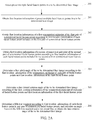
- FIG. 1 is a flowchart of a method for determining a face rotation angle according to an embodiment of the present invention. Referring to FIG. 1 , the method includes the following steps.
- step 101 Obtain first location information of preset multiple facial feature points in a to-be-determined face image, a quantity of the multiple facial feature points being an odd number, the multiple facial feature points including multiple pairs of symmetrical facial feature points and one first facial feature point, and the multiple facial feature points being not coplanar.
- step 102 Obtain, according to first location information of facial feature points included in each pair of facial feature points of the multiple pairs of facial feature points, first location information of a symmetrical midpoint of each pair of facial feature points.
- step 200 Detect preset multiple facial feature points in a to-be-determined face image.
- the preset multiple facial feature points are selected from points that are easily recognized in a face, and a preset facial feature point is located on a contour of a facial organ, and may be a turning point of the contour of the facial organ.
- a preset feature point may be an inner eye corner, an outer eye corner, a mouth corner, the tail of a brow, the head of a brow, or a nasal tip, both the inner eye corner and the outer eye corner are turning points of a contour of an eye
- the mouth corner is a turning point of a contour of a mouth
- the tail of the brow and the head of the brow are turning points of a contour of an eyebrow
- the nasal tip is a turning point of a contour of a nose.
- a quantity of the preset multiple facial feature points is an odd number.
- the quantity may be 5 or 7
- the preset multiple facial feature points include multiple pairs of symmetrical facial feature points and one remaining first facial feature point, and the multiple facial feature points are not coplanar.
- the multiple facial feature points may include five facial feature points, and the five facial feature points include a first pair of symmetrical facial feature points, a second pair of symmetrical facial feature points, and one remaining first facial feature point.
- the first pair of symmetrical facial feature points may be two inner eye corners
- the second pair of symmetrical facial feature points may be two mouth corners
- the remaining first facial feature point is a nasal tip.
- This step may be: first, a face in the to-be-determined face image is detected by using a face detection technology, and then the first pair of symmetrical facial feature points, that is, the two inner eye corners, the second pair of symmetrical facial feature points, that is, the two mouth corners, and the remaining first facial feature point, that is, the nasal tip are detected in the face by using a facial feature point detection technology.
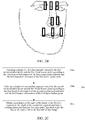
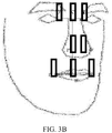
- FIG. 2B is a diagram of tagging feature points in a to-be-determined face image according to this embodiment (where the feature points in the figure not only include detected facial feature points, but also include a symmetrical midpoints formed by detected symmetrical facial feature points and another point, and are described in the following content). As shown in FIG.
- step 201 Obtain first location information of preset multiple facial feature points in a to-be-determined face image.
- a facial feature point After a facial feature point is detected, coordinates of the facial feature point are automatically obtained, where a coordinate form of the facial feature point is ( x, y ) , and coordinates after positioning are output to a terminal. In this way, the terminal may directly obtain a coordinate location of the facial feature point after positioning.
- coordinate locations obtained by the terminal of the preset first pair of symmetrical facial feature points are separately C' ( x 1 , y 1 ) and D' ( x 2 , y 2 )
- coordinate locations obtained by the terminal of the second pair of symmetrical facial feature points are separately E' ( x 3 , y 3 ) and F' ( x 4 , y 4 )
- a coordinate location obtained by the terminal of the remaining first facial feature point (the nasal tip) is N' ( x 5 , y 5 ).
- the obtained coordinate locations of the five facial feature points are separately: C' (0, 0), D' (2, 2), E' (1, -2), F' (2, -1), and N' (1.5, 0).
- the first location information of the first symmetrical midpoint of the first pair of symmetrical facial feature points is A' (1, 1).
- step 203 Obtain first location information of a second symmetrical midpoint of the second pair of symmetrical facial feature points according to first location information of each facial feature point included in the second pair of symmetrical facial feature points.
- the face rotation angle of the to-be-determined face image may be the face pitch angle or a face lateral rotation angle.
- a method for determining a face pitch angle and a method for determining a face lateral rotation angle are separately described below.
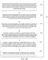
- the face pitch angle of the to-be-determined face image is determined according to the first location information of the symmetrical midpoint of each pair of facial feature points and first location information of the first facial feature point. Referring to FIG. 2C , the method may include the following steps.
- step 204a Calculate a length of a first line segment formed by the first symmetrical midpoint and the first facial feature point according to the first location information of the first symmetrical midpoint and the first location information of the first facial feature point.
- step 204b Calculate a length of a second line segment formed by the second symmetrical midpoint and the first facial feature point according to the first location information of the second symmetrical midpoint and the first location information of the first facial feature point.
- the first ratio of the length A'N' of the first line segment to the length B'N' of the second line segment is calculated, a pre-established correspondence between the first ratio and the face pitch angle is queried according to the first ratio (for a process of establishing the correspondence, refer to the following steps 302a to 302e), and the face pitch angle corresponding to the calculated first ratio is queried from the correspondence, and the face pitch angle is determined as the face pitch angle of the to-be-determined face image.
- a first ratio closest to the first ratio calculated in this step is determined from all the first ratios in the correspondence, and then a face pitch angle corresponding to the closest first ratio is used as the face pitch angle corresponding to the first ratio calculated in this step.
- Subtraction is performed on each first ratio included in the pre-established correspondence between the first ratio and the face pitch angle and the first ratio calculated in this step, to obtain a first ratio difference, then an absolute value operation is performed on each first ratio difference, values obtained after the absolute value operation are compared, to obtain a minimum absolute value, then a first ratio corresponding to the minimum absolute value (a a first ratio included in the correspondence between the first ratio and the face pitch angle) is obtained, and the first ratio is determined as the first ratio closest to the first ratio calculated in this step.
- step 205 Determine a face lateral rotation angle of the to-be-determined face image according to the first location information of the symmetrical midpoint of each pair of facial feature points and first location information of the first facial feature point.
- the face lateral rotation angle of the to-be-determined face image is determined according to the first location information of the symmetrical midpoint of each pair of facial feature points, the first location information of the first facial feature point, and the face pitch angle that is determined by using the foregoing process.
- the method may include the following steps.
- step 205a Calculate a first vertical distance from the first facial feature point to a third line segment and a length of the third line segment according to the first location information of the first symmetrical midpoint, the first location information of the second symmetrical midpoint, and the first location information of the first facial feature point.
- the first location information of the first symmetrical midpoint is A' ( x 6 , y 6 ). It can be learned from step 203 that, the first location information of the second symmetrical midpoint is B' ( x 7 , y 7 ). It can be learned from step 201 that, the first location information of the first facial feature point is N' ( x 5 , y 5 ).
- the third line segment is a line segment A'B' formed by the first symmetrical midpoint A' ( x 6 , y 6 ) and the second symmetrical midpoint B' ( x 7 , y 7 ), and the first vertical distance from the first facial feature point to the third line segment is calculated by using the following method: first, a straight line passing through the point A' and the point B' is tagged as a straight line c, a general straight-line equation of the straight line c is calculated according to the first location information of the point A' and the point B', and then a first vertical distance from the first facial feature point N' to the straight line c is calculated according to the first location information of the first facial feature point N'. Details are as follows:
- the straight line c passing through the point A' ( x 6 , y 6 ) and the point B' ( x 7 , y 7 ) may be further calculated by using another method, and details are not described herein.
- the straight line c is a straight line passing through the point A' ( x 6 , y 6 ) and the point B' ( x 7 , y 7 )
- the distance d from the first facial feature point N' ( x 5 , y 5 ) to the straight line c is a second vertical distance from the first facial feature point N' ( x 5 , y 5 ) to the third line segment A'B'. Therefore, the first vertical distance is the distance d.
- step 205b Obtain, according to the face pitch angle and from a correspondence between the face pitch angle and a third ratio, the corresponding third ratio.
- a pre-established correspondence between a third ratio and a face pitch angle is queried according to the face pitch angle determined in step 204 (for a process of establishing the correspondence, refer to subsequent steps 303a to 303f), a third ratio corresponding to a face pitch angle is queried from the correspondence, the face pitch angle is the face pitch angle determined in step 204, and the third ratio is tagged as e.
- a face pitch angle closest to the face pitch angle calculated in step 204 is determined from all the face pitch angles, and then a third ratio corresponding to the closest face pitch angle is used as the third ratio corresponding to the face pitch angle.
- Subtraction is performed on each face pitch angle included in the pre-established correspondence between the third ratio and the face pitch angle and the face pitch angle determined in step 204, to obtain a face pitch angle difference, then an absolute value operation is performed on each face pitch angle difference, values obtained after the absolute value operation are compared, to obtain a minimum absolute value, then a face pitch angle corresponding to the minimum absolute value (a face pitch angle included in the correspondence between the third ratio and the face pitch angle) is obtained, and the face pitch angle is determined as the face pitch angle closest to the face pitch angle calculated in step 204.
- step 205c Calculate the length of the fourth line segment according to the third ratio and the length of the third line segment.
- This step may be: The second ratio of the first vertical distance d to the length the fourth line segment AB is calculated, a pre-established correspondence between the second ratio and the face lateral rotation angle is queried according to the second ratio (for a process of establishing the correspondence, refer to subsequent steps 304a to 304b), and a face lateral rotation angle corresponding to a second ratio same as the calculated second ratio is queried from the correspondence, and the face lateral rotation angle is determined as the face lateral rotation angle of the to-be-determined face image.
- a second ratio closest to the second ratio calculated in this step is determined from all the second ratios in the correspondence, and then a face lateral rotation angle corresponding to the closest second ratio is used as the face lateral rotation angle corresponding to the second ratio calculated in this step.
- Subtraction is performed on each second ratio included in the pre-established correspondence between the second ratio and the face lateral rotation angle and the second ratio calculated in this step, to obtain a second ratio difference, then an absolute value operation is performed on each second ratio difference, values obtained after the absolute value operation are compared, to obtain a minimum absolute value, then a second ratio corresponding to the minimum absolute value (a a second ratio included in the correspondence between the second ratio and the face lateral rotation angle) is obtained, and the second ratio is determined as the second ratio closest to the second ratio calculated in this step.
- step 206 Determine a fifth line segment according to first location information of each facial feature point in any pair of symmetrical facial feature points, and calculate an angle between the fifth line segment and a horizontal line, to obtain the face rotation angle of the to-be-determined face image.
- the face rotation angle is an angle obtained by rotating the face horizontally when a frontal direction of the face is always forward.
- a cosine value of ⁇ is calculated.
- a first correspondence is a correspondence between a first ratio and a preset face pitch angle
- a second correspondence is a correspondence between a third ratio and a preset face pitch angle
- a third correspondence is a correspondence between a second ratio and a preset face lateral rotation angle.
- step 301 Obtain second location information of the preset multiple facial feature points in a first face image.
- the meaning of the preset multiple facial feature points is the same as that of the foregoing preset multiple facial feature points, and details are not described herein.
- the second location information is obtained by placing the face in a three-dimensional rectangular coordinate system (three coordinate axes are used and are separately an x axis, a y axis, and a z axis, and the x axis, the y axis, and the z axis are three axial directions perpendicular to each other, and are a method for denoting a space).
- the three-dimensional rectangular coordinate system may be any three-dimensional rectangular coordinate system. Therefore, a coordinate form of the second location information of the facial feature point obtained by using the three-dimensional rectangular coordinate system is (x, y, z).
- the second location information of the preset multiple facial feature points in the first face image may be obtained by using the following method: first, a face is placed as a frontal face, and the frontal face is rotated according to a preset angle difference between each two neighboring face rotation angles; after the frontal face is rotated by the preset angle difference each time, a face image is shot, and coordinate locations of preset multiple facial feature points of the shot face image are obtained, and are tagged as second location information.
- step 302 Establish a correspondence between a first ratio and the preset face pitch angle according to the second location information of the preset multiple facial feature points.
- the first correspondence is the correspondence between the first ratio and the preset face pitch angle.
- FIG. 3C is a method flowchart of a process of establishing a correspondence between a first ratio and a preset face pitch angle, and the method includes the following steps.
- step 302a Obtain second location information of a fifth symmetrical midpoint of the first pair of symmetrical facial feature points according to second location information of each facial feature point included in the first pair of symmetrical facial feature points.
- the second pair of symmetrical facial feature points are two mouth corners I' ( x 11 , y 11 , z 11 ) and J' ( x 12 , y 12 , z 12 ). Still referring to FIG.
- step 302d Calculate a length of a seventh line segment formed by the sixth symmetrical midpoint and the first facial feature point according to the second location information of the sixth symmetrical midpoint and the second location information of the first facial feature point.
- the second location information of the sixth symmetrical midpoint is L' ( x 15 , y 15 , z 15 )
- the first facial feature point is a nasal tip O' ( x 13 , y 13 , z 13 )
- the seventh line segment formed by the sixth symmetrical midpoint and the first facial feature point is a length of a line segment L'O' formed by L' ( x 15 , y 15 , z 15 ) and the point O' ( x 13 , y 13 , z 13 )
- the length of the seventh line segment is calculated by using a formula for a distance between two points, and specific calculation is shown in the following formula (27):
- L ′ O ′ x 15 ⁇ x 13 2 + y 15 ⁇ y 13 2 + z 15 ⁇ z 13 2
- step 302e Establish a correspondence between a first ratio of the sixth line segment to the seventh line segment and the preset face pitch angle.
- the sixth line segment is K'O'
- the seventh line segment is L'O'
- the first ratio is a ratio of K'O' to L'O'.
- a correspondence between the first ratio and the preset face pitch angle is obtained by using the following method: a face is rotated; when a face rotation angle is a preset first face pitch angle, the face is stopped from being rotating; in a case of the first face pitch angle, a ratio of K'O' to L'O' is calculated, to obtain a first first ratio, and a correspondence between the first first ratio and the preset first face pitch angle is stored; and the face continues to be rotated; when the face rotation angle is a preset second face pitch angle, in a case of the second face pitch angle, a ratio of K'O' to L'O' is calculated, to obtain a second first ratio, and a correspondence between the second first ratio and the preset second face pitch angle is stored; and the foregoing steps are repeated, until correspondences between all first ratios
- step 303 Establish a correspondence between a third ratio and the preset face pitch angle according to the second location information of the preset multiple facial feature points.
- FIG. 3D is a method flowchart of a process of establishing a correspondence between a third ratio and a preset face pitch angle, and the method includes the following steps.
- step 303a Obtain third location information of each facial feature point included in the first pair of symmetrical facial feature points in the frontal face image of the face, and third location information of each facial feature point included in the second pair of symmetrical facial feature points in the frontal face image.
- FIG. 3E includes multiple facial feature points in a frontal face image when a first face image shown this embodiment is the frontal face image.
- the first pair of symmetrical facial feature points are two inner eye corners and are separately tagged as G and H
- third location information of G and third location information of H in the frontal face image of the face are respectively G ( x 16 , y 16 , z 16 ) and H ( x 17 , y 17 , z 17 ).
- the second pair of symmetrical facial feature points are two mouth corners and are separately tagged as I' and J', and third location information of I' and third location information of J' in the frontal face image are respectively I' ( x 18 , y 18 , z 18 ) and J' ( x 19 , y 19 , z 19 ).
- step 303b Obtain third location information of a seventh symmetrical midpoint of the first pair of symmetrical facial feature points according to the third location information of each facial feature point included in the first pair of symmetrical facial feature points.
- step 303c Obtain third location information of an eighth symmetrical midpoint of the second pair of symmetrical facial feature points according to the third location information of each facial feature point included in the second pair of symmetrical facial feature points.
- the second pair of symmetrical facial feature points are two mouth corners I ( x 20 , y 20 , z 20 ) and J ( x 21 , y 21 , Z 21 )
- an eighth symmetrical midpoint of the second pair of symmetrical facial feature points is a midpoint of a line segment IJ formed by the points I ( x 20 , y 20 , z 20 ) and J ( x 21 , y 21 , z 21 ), the midpoint is tagged as L
- a coordinate location of L ( x 22 , y 22 , z 22 ) is obtained by using a midpoint calculation formula, and specific calculation is shown in the following formulas (31), (32) and (33):
- x 22 x 20 + x 21 2
- step 303d Calculate a length of an eighth line segment formed by the fifth symmetrical midpoint and the sixth symmetrical midpoint according to the second location information of the fifth symmetrical midpoint and the second location information of the sixth symmetrical midpoint.
- the second location information of the fifth symmetrical midpoint is K' ( x 14 , y 14 , z 14 )
- the second location information of the sixth symmetrical midpoint is L' ( x 15 , y 15 , z 15 )
- the length of the eighth line segment K'L' formed by the fifth symmetrical midpoint K' ( x 14 , y 14 , z 14 ) and the sixth symmetrical midpoint L' ( x 15 , y 15 , z 15 ) is a distance from the point K' ( x 14 , y 14 , z 14 ) to the point L' ( x 15 , y 15 , z 15 ), and is calculated by using a formula for a distance between two points, and specific calculation is shown in the following formula (34):
- K ′ L ′ x 15 ⁇ x 14 2 + y 15 ⁇ y 14 2 + z 15 ⁇ z 14 2
- step 303e Calculate a length of a ninth line segment formed by the seventh symmetrical midpoint and the eighth symmetrical midpoint according to the third location information of the seventh symmetrical midpoint and the third location information of the eighth symmetrical midpoint.
- step 303f Establish a correspondence between a third ratio of the eighth line segment to the ninth line segment and the preset face pitch angle.
- the eighth line segment is K'L'
- the ninth line segment is KL
- the third ratio is a ratio of K'L' to KL.
- a correspondence between the third ratio and the preset face pitch angle is obtained by using the following method: a face is rotated; when a face rotation angle is a preset first face pitch angle, the face is stopped from being rotating; in a case of the first face pitch angle, a ratio of K'L' to KL is calculated, to obtain a first third ratio, and a correspondence between the first third ratio and the preset first face pitch angle is stored; and the face continues to be rotated; when the face rotation angle is a preset second face pitch angle, in a case of the second face pitch angle, a ratio of K'L' to KL is calculated, to obtain a second third ratio, and a correspondence between the second third ratio and the preset second face pitch angle is stored; and the foregoing steps are repeated, until correspondences between all third ratios and preset face pitch angles are stored
- step 304 Establish a correspondence between a second ratio and the preset face lateral rotation angle according to the second location information of the preset multiple facial feature points.
- FIG. 3F is a method flowchart of a process of establishing a correspondence between a second ratio and a preset face lateral rotation angle, and the method includes the following steps.
- step 304a Calculate a second vertical distance from the first facial feature point to the eighth line segment according to the second location information of the fifth symmetrical midpoint, the second location information of the sixth symmetrical midpoint, and the second location information of the first facial feature point.
- the second location information of the fifth symmetrical midpoint is K' ( x 14 , y 14 , z 14 ). It can be learned from step 302b that, the second location information of the sixth symmetrical midpoint is L' ( x 15 , y 15 , z 15 ). It can be learned from step 205 that, the second location information of the first facial feature point is O' ( x 13 , y 13 , z 13 ), and the second vertical distance from the first facial feature point O' ( x 13 , y 13 , z 13 ) to the eighth line segment K'L' is calculated by using the following process:
- the straight line a passing through the point K' ( x 14 , y 14 , z 14 ) and the point L' ( x 15 , y 15 , z 15 ) may be further calculated by using another method, and details are not described herein.
- the straight line a is a straight line passing through the K' ( x 14 , y 14 , z 14 ) and the point L' ( x 15 , y 15 , z 15 )
- the distance b from the first facial feature point O' ( x 13 , y 13 , z 13 ) to the straight line a is a second vertical distance from the first facial feature point O' ( x 13 , y 13 , z 13 ) to the eighth line segment K'L'. Therefore, the second vertical distance is the distance b.
- step 304b Establish a correspondence between a second ratio of the second vertical distance to the ninth line segment and the preset face lateral rotation angle.
- the second vertical distance is b
- the ninth line segment is KL
- the second ratio is a ratio of b to KL.
- a correspondence between the second ratio and the preset face lateral rotation angle is obtained by using the following method: a face is rotated; when a face rotation angle is a preset first face lateral rotation angle, the face is stopped from being rotating; in a case of the first face lateral rotation angle, a ratio of b to KL is calculated, to obtain a first second ratio, and a correspondence between the first second ratio and the preset first face lateral rotation angle is stored; and the face continues to be rotated; when the face rotation angle is a preset second face lateral rotation angle, in a case of the second face lateral rotation angle, a ratio of b to KL is calculated, to obtain a second second ratio, and a correspondence between the second second ratio and the preset second face lateral rotation angle is stored; and the foregoing steps are repeated, until correspondences between all second ratios and prese
- a 3D model of a frontal face is rotated according to a preset angle
- coordinate information of a facial feature point is obtained each time the 3D model is rotated by a preset angle
- a correspondence between a line segment ratio and a preset face rotation angle is established according to the obtained coordinate information. Because the preset angle is relatively small, the line segment ratio or the face rotation angle in the correspondence is relatively precise.
- the line segment ratio or the face rotation angle may be directly obtained from the correspondence in a process of determining the face rotation angle, thereby reducing a time needed for determining the face rotation angle, and improving efficiency of determining the face rotation angle.
- the multiple facial feature points include five facial feature points, and the five facial feature points include a first pair of symmetrical facial feature points, a second pair of symmetrical facial feature points, and one remaining first facial feature point.
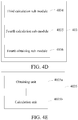
- the second obtaining sub-module 4022 is configured to obtain first location information of a second symmetrical midpoint of the second pair of symmetrical facial feature points according to first location information that is of each facial feature point included in the second pair of symmetrical facial feature points and that is obtained by the first obtaining module 401.
- the fourth obtaining sub-module 4036 is configured to obtain, according to a second ratio of the first vertical distance calculated by the third calculation sub-module 4034 to the length of the fourth line segment calculated by the fourth calculation sub-module 4035 and from a correspondence between the second ratio and a face lateral rotation angle, the face lateral rotation angle of the to-be-determined face image.
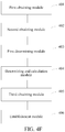
- the apparatus further includes:
- the preset face rotation angle includes a preset face pitch angle.
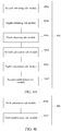
- FIG. 4G is a structural block diagram of an establishment module 406 for establishing a correspondence between a first ratio and a preset face pitch angle according to another embodiment of the present invention.
- the establishment module 406 includes but is not limited to including: a fifth obtaining sub-module 4061, a sixth obtaining sub-module 4062, a fifth calculation sub-module 4063, a sixth calculation sub-module 4064, and a first establishment sub-module 4065.
- the fifth obtaining sub-module 4061 is configured to obtain second location information of a fifth symmetrical midpoint of the first pair of symmetrical facial feature points according to second location information that is of each facial feature point included in the first pair of symmetrical facial feature points and that is obtained by the third obtaining module 405.
- the sixth obtaining sub-module 4062 is configured to obtain second location information of a sixth symmetrical midpoint of the second pair of symmetrical facial feature points according to first location information that is of each facial feature point included in the second pair of symmetrical facial feature points and that is obtained by the third obtaining module 405.
- the fifth calculation sub-module 4063 is configured to calculate a length of a sixth line segment formed by the fifth symmetrical midpoint and the first facial feature point according to the second location information that is of the fifth symmetrical midpoint and that is obtained by the fifth obtaining sub-module 4061 and the second location information that is of the first facial feature point and that is obtained by the third obtaining module 405.
- the first establishment sub-module 4065 is configured to establish a correspondence between a first ratio of the sixth line segment calculated by the fifth calculation sub-module 4063 to the seventh line segment calculated by the sixth calculation sub-module 4064 and the preset face pitch angle.
- FIG. 4H is a structural block diagram of an establishment module 406 for establishing a correspondence between a third ratio and a preset face pitch angle according to still another embodiment of the present invention.
- the establishment module 406 includes but is not limited to including: a seventh obtaining sub-module 406a, an eighth obtaining sub-module 406b, a ninth obtaining sub-module 406c, a seventh calculation sub-module 406d, an eighth calculation sub-module 406e, and a second establishment sub-module 406f.
- the ninth obtaining sub-module 406c is configured to obtain third location information of an eighth symmetrical midpoint of the second pair of symmetrical facial feature points according to the third location information that is of each facial feature point included in the second pair of symmetrical facial feature points and that is obtained by the seventh obtaining sub-module 406a.
- the seventh calculation sub-module 406d is configured to calculate a length of an eighth line segment formed by the fifth symmetrical midpoint and the sixth symmetrical midpoint according to the second location information that is of the fifth symmetrical midpoint and that is obtained by the fifth obtaining sub-module 4061 and the second location information that is of the sixth symmetrical midpoint and that is obtained by the sixth obtaining sub-module 4062.
- the eighth calculation sub-module 406e is configured to calculate a length of a ninth line segment formed by the seventh symmetrical midpoint and the eighth symmetrical midpoint according to the third location information that is of the seventh symmetrical midpoint and that is obtained by the eighth obtaining sub-module 406b and the third location information that is of the eighth symmetrical midpoint and that is obtained by the ninth obtaining sub-module 406c.
- the second establishment sub-module 406f is configured to establish a correspondence between a third ratio of the eighth line segment calculated by the seventh calculation sub-module 406d to the ninth line segment calculated by the eighth calculation sub-module 406e and the preset face pitch angle.
- FIG. 4I is a structural block diagram of an establishment module 406 for establishing a correspondence between a second ratio and a preset face lateral rotation angle according to yet another embodiment of the present invention.
- the establishment module 406 further includes but is not limited to including: a ninth calculation sub-module 4066, and a third establishment sub-module 4067.
- the wireless communication may use any communications standard or protocol, which includes, but is not limited to, Global System for Mobile communications (GSM), General Packet Radio Service (GPRS), Code Division Multiple Access (CDMA), Wideband Code Division Multiple Access (WCDMA), Long Term Evolution (LTE), e-mail, Short Messaging Service (SMS), and the like.
- GSM Global System for Mobile communications
- GPRS General Packet Radio Service
- CDMA Code Division Multiple Access
- WCDMA Wideband Code Division Multiple Access
- LTE Long Term Evolution
- SMS Short Messaging Service
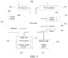
- the memory 520 may be configured to store a software program and module.
- the processor 580 runs the software program and module stored in the memory 520, to implement various functional applications and data processing of the electronic device 500.
- the memory 520 may mainly include a program storage area and a data storage area.
- the program storage area may store an operating system, an application program required by at least one function (such as a sound playback function and an image display function), and the like.
- the data storage area may store data (such as audio data and an address book) created according to use of the electronic device 500, and the like.
- the memory 520 may include a high speed random access memory, and may also include a non-volatile memory, such as at least one magnetic disk storage device, a flash memory, or another volatile solid storage device.
- the input unit 530 may be configured to receive input digit or character information, and generate key signal input related to the user setting and function control of the electronic device 500.
- the input unit 530 may include a touch panel 531 and another input device 532.
- the touch panel 531 may also be referred to as a touch screen, and may collect a touch operation of a user on or near the touch panel (such as an operation of a user on or near the touch panel 531 by using any suitable object or attachment, such as a finger or a touch pen), and drive a corresponding connection apparatus according to a preset program.
- the touch panel 531 may include two parts: a touch detection apparatus and a touch controller.
- the display unit 540 may be configured to display information input by the user or information provided for the user, and various menus of the electronic device 500.
- the display unit 540 may include a display panel 541.
- the display panel 541 may be configured by using a liquid crystal display (LCD), an organic light-emitting diode (OLED), or the like.
- the touch panel 531 may cover the display panel 541. After detecting a touch operation on or near the touch panel 531, the touch panel 531 transfers the touch operation to the processor 580, so as to determine a type of a touch event. Then, the processor 580 provides corresponding visual output on the display panel 541 according to the type of the touch event.
- the electronic device 500 may further include at least one sensor 550, such as a gyroscope sensor, a magnetic induction sensor, an optical sensor, a motion sensor and another sensor.
- the optical sensor may include an ambient light sensor and a proximity sensor.
- the ambient light sensor may adjust brightness of the display panel 541 according to brightness of ambient light.
- the proximity sensor may turn off the display panel 541 and/or backlight when the electronic device 500 is moved to an ear.
- an acceleration sensor may detect magnitude of accelerations at various directions (which generally are triaxial), may detect magnitude and a direction of the gravity when static, and may be configured to identify an application of an electronic device gesture (such as switchover between horizontal and vertical screens, a related game, and gesture calibration of a magnetometer), a related function of vibration identification (such as a pedometer and a knock).
- an electronic device gesture such as switchover between horizontal and vertical screens, a related game, and gesture calibration of a magnetometer
- a related function of vibration identification such as a pedometer and a knock.
- Other sensor such as a barometer, a hygrometer, a thermometer, and an infrared sensor, which may be configured in the electronic device 500 are not further described herein.
- the audio circuit 560, a loudspeaker 561, and a microphone 562 may provide audio interfaces between the user and the electronic device 500.
- the audio circuit 560 may transmit, to the loudspeaker 561, an electric signal converted from received audio data.
- the loudspeaker 561 converts the electric signal into a sound signal for output.
- the microphone 562 converts a collected sound signal into an electric signal.
- the audio circuit 560 receives the electric signal and converts the electric signal into audio data, and outputs the audio data to the processor 580 for processing. Then, the processor 580 sends the audio data to, for example, another terminal by using the RF circuit 510, or outputs the audio data to the memory 520 for further processing.
- Wi-Fi belongs to a short distance wireless transmission technology.
- the electronic device 500 may help, by using the Wi-Fi module 570, a user to receive and send an e-mail, browse a webpage, access stream media, and the like, which provides wireless broadband Internet access for the user.
- FIG. 5 shows the Wi-Fi module 570, it may be understood that, the Wi-Fi module 570 does not belong to a necessary constitution of the electronic device 500, and can be ignored according to demands without changing the scope of the essence of the present disclosure.
- the processor 580 is a control center of the electronic device 500, and connects to various parts of the entire electronic device by using various interfaces and lines. By running or executing the software program and/or module stored in the memory 520, and invoking data stored in the memory 520, the processor 180 performs various functions and data processing of the electronic device 500, thereby performing overall monitoring on the electronic device.
- the processor 580 may include one or more processing units.
- the processor 580 may integrate an application processor and a modem.
- the application processor mainly processes an operating system, a user interface, an application program, and the like.
- the modem mainly processes wireless communication. It may be understood that, the foregoing modem may also not be integrated into the processor 580.
- the electronic device 500 further includes the power supply 582 (such as a battery) for supplying power to the components.
- the power supply may logically connect to the processor 582 by using a power supply management system, thereby implementing functions, such as charging, discharging, and power consumption management, by using the power supply management system.
- the camera 590 is generally formed by a lens, an image sensor, an interface, a digital signal processor, a CPU, a display screen, and the like.
- the lens is fixed above the image sensor, and may change focusing by manually adjusting the lens.
- the image sensor is equivalent to a "film" of a conventional camera, and is the heart of the camera for collecting an image.
- the interface is configured to connect the camera to a mainboard of the electronic device by using a flat cable and a board-to-board connector and in a spring connection manner, and send the collected image to the memory 520.
- the digital signal processor processes the collected image by using a mathematical operation, converts a collected analog image into a digital image, and sends the digital image to the memory 520 by using the interface.
- the electronic device 500 may further include a Bluetooth module, and the like, which are not further described herein.
- the electronic device 500 further includes a memory, and one or more programs, where the one or more programs are stored in the memory, and are configured to be executed by the one or more processors.
- the one or more programs include an instruction used to execute the following operations:
- the memory of the electronic device 500 further includes an instruction used to execute the following operation: the multiple facial feature points include five facial feature points, and the five facial feature points include a first pair of symmetrical facial feature points, a second pair of symmetrical facial feature points, and one remaining first facial feature point.
- the memory of the electronic device 500 further includes an instruction used to execute the following operations: the obtaining, according to first location information of facial feature points included in each pair of facial feature points of the multiple pairs of facial feature points, first location information of a symmetrical midpoint of each pair of facial feature points includes:
- the memory of the electronic device 500 further includes an instruction used to execute the following operations: the determining a face rotation angle of the to-be-determined face image according to the first location information of the symmetrical midpoint of each pair of facial feature points and first location information of the first facial feature point includes:
- the memory of the electronic device 500 further includes an instruction used to execute the following operations:
- the memory of the electronic device 500 further includes an instruction used to execute the following operations: before the determining a face rotation angle of the to-be-determined face image, the method further includes:
- the memory of the electronic device 500 further includes an instruction used to execute the following operations:
- the units described as separate parts may or may not be physically separate, and the parts displayed as units may or may not be physical units, may be located in one position, or may be distributed on a plurality of network units. Some or all of the units may be selected according to actual needs to achieve the objectives of the solutions of the embodiments.
Landscapes
- Engineering & Computer Science (AREA)
- Health & Medical Sciences (AREA)
- Oral & Maxillofacial Surgery (AREA)
- Physics & Mathematics (AREA)
- Theoretical Computer Science (AREA)
- General Physics & Mathematics (AREA)
- General Health & Medical Sciences (AREA)
- Human Computer Interaction (AREA)
- Multimedia (AREA)
- Computer Vision & Pattern Recognition (AREA)
- Geometry (AREA)
- General Engineering & Computer Science (AREA)
- Image Analysis (AREA)
- Image Processing (AREA)
- Quality & Reliability (AREA)
Applications Claiming Priority (2)
| Application Number | Priority Date | Filing Date | Title |
|---|---|---|---|
| CN201610041938.7A CN106991367B (zh) | 2016-01-21 | 2016-01-21 | 确定人脸转动角度的方法和装置 |
| PCT/CN2017/070607 WO2017124929A1 (fr) | 2016-01-21 | 2017-01-09 | Procédé et dispositif pour déterminer l'angle de rotation d'un visage humain, et support de stockage informatique |
Publications (3)
| Publication Number | Publication Date |
|---|---|
| EP3407245A1 true EP3407245A1 (fr) | 2018-11-28 |
| EP3407245A4 EP3407245A4 (fr) | 2019-01-16 |
| EP3407245B1 EP3407245B1 (fr) | 2023-09-20 |
Family
ID=59361342
Family Applications (1)
| Application Number | Title | Priority Date | Filing Date |
|---|---|---|---|
| EP17740960.4A Active EP3407245B1 (fr) | 2016-01-21 | 2017-01-09 | Procédé et dispositif pour déterminer l'angle de rotation d'un visage humain, et moyen de stockage lisible par ordinateur |
Country Status (6)
| Country | Link |
|---|---|
| US (1) | US10713812B2 (fr) |
| EP (1) | EP3407245B1 (fr) |
| JP (1) | JP6668475B2 (fr) |
| KR (1) | KR102144489B1 (fr) |
| CN (1) | CN106991367B (fr) |
| WO (1) | WO2017124929A1 (fr) |
Families Citing this family (35)
| Publication number | Priority date | Publication date | Assignee | Title |
|---|---|---|---|---|
| JP6304999B2 (ja) * | 2013-10-09 | 2018-04-04 | アイシン精機株式会社 | 顔検出装置、方法およびプログラム |
| WO2018033137A1 (fr) * | 2016-08-19 | 2018-02-22 | 北京市商汤科技开发有限公司 | Procédé, appareil et dispositif électronique d'affichage d'un objet de service dans une image vidéo |
| CN109389018B (zh) * | 2017-08-14 | 2020-12-25 | 杭州海康威视数字技术股份有限公司 | 一种人脸角度识别方法、装置及设备 |
| CN107679446B (zh) * | 2017-08-17 | 2019-03-15 | 平安科技(深圳)有限公司 | 人脸姿态检测方法、装置及存储介质 |
| CN107679497B (zh) * | 2017-10-11 | 2023-06-27 | 山东新睿信息科技有限公司 | 视频面部贴图特效处理方法及生成系统 |
| CN107818305B (zh) | 2017-10-31 | 2020-09-22 | Oppo广东移动通信有限公司 | 图像处理方法、装置、电子设备和计算机可读存储介质 |
| JP6791108B2 (ja) * | 2017-12-11 | 2020-11-25 | オムロン株式会社 | 顔位置検出装置 |
| CN111033508B (zh) | 2018-04-25 | 2020-11-20 | 北京嘀嘀无限科技发展有限公司 | 一种识别身体运动的系统和方法 |
| CN109086727B (zh) * | 2018-08-10 | 2021-04-30 | 北京奇艺世纪科技有限公司 | 一种确定人体头部的运动角度的方法、装置及电子设备 |
| CN109165606B (zh) * | 2018-08-29 | 2019-12-17 | 腾讯科技(深圳)有限公司 | 一种车辆信息的获取方法、装置以及存储介质 |
| CN110909568A (zh) * | 2018-09-17 | 2020-03-24 | 北京京东尚科信息技术有限公司 | 用于面部识别的图像检测方法、装置、电子设备及介质 |
| CN111460871B (zh) * | 2019-01-18 | 2023-12-22 | 北京市商汤科技开发有限公司 | 图像处理方法及装置、存储介质 |
| CN109949237A (zh) * | 2019-03-06 | 2019-06-28 | 北京市商汤科技开发有限公司 | 图像处理方法及装置、图像设备及存储介质 |
| CN110032941B (zh) * | 2019-03-15 | 2022-06-17 | 深圳英飞拓科技股份有限公司 | 人脸图像检测方法、人脸图像检测装置及终端设备 |
| US11120569B2 (en) * | 2019-06-24 | 2021-09-14 | Synaptics Incorporated | Head pose estimation |
| CN110879986A (zh) * | 2019-11-21 | 2020-03-13 | 上海眼控科技股份有限公司 | 人脸识别的方法、设备和计算机可读存储介质 |
| CN113011230B (zh) * | 2019-12-20 | 2024-12-03 | 杭州萤石软件有限公司 | 一种人脸偏转角度的确定方法及装置 |
| CN111219940B (zh) * | 2019-12-26 | 2023-09-22 | 青岛海尔智能技术研发有限公司 | 冰箱内灯光控制的方法及装置、冰箱 |
| KR102301769B1 (ko) * | 2020-01-16 | 2021-09-16 | 디디에이치 주식회사 | 교정적 치아배열 형상 생성 방법 및 장치 |
| CN111444775B (zh) * | 2020-03-03 | 2023-10-27 | 平安科技(深圳)有限公司 | 人脸关键点修正方法、装置以及计算机设备 |
| DE102020206350A1 (de) * | 2020-05-20 | 2022-01-27 | Robert Bosch Gesellschaft mit beschränkter Haftung | Verfahren zur Detektion von Vergleichspersonen zu einer Suchperson, Überwachungsanordnung, insbesondere zur Umsetzung des Verfahrens, sowie Computerprogramm und computerlesbares Medium |
| CN113705280B (zh) * | 2020-05-21 | 2024-05-10 | 北京聚匠艺传媒有限公司 | 一种基于面部特征的人机交互方法及装置 |
| CN113703564B (zh) * | 2020-05-21 | 2024-08-23 | 北京聚匠艺传媒有限公司 | 一种基于面部特征的人机交互设备及系统 |
| WO2021251184A1 (fr) * | 2020-06-11 | 2021-12-16 | ソニーグループ株式会社 | Dispositif de traitement d'image, procédé de traitement d'image et support d'enregistrement |
| CN111914783B (zh) * | 2020-08-10 | 2024-10-01 | 深圳市视美泰技术股份有限公司 | 人脸偏转角度的确定方法、装置、计算机设备及介质 |
| CN112069954B (zh) * | 2020-08-26 | 2023-12-19 | 武汉普利商用机器有限公司 | 一种活体微表情检测方法及系统 |
| CN112183421B (zh) * | 2020-10-09 | 2024-07-26 | 江苏提米智能科技有限公司 | 一种人脸图像评估方法、装置、电子设备及存储介质 |
| CN112395949B (zh) * | 2020-10-21 | 2023-06-20 | 天津中科智能识别产业技术研究院有限公司 | 多目标人群的虹膜图像获取装置与方法 |
| CN112446347B (zh) * | 2020-12-10 | 2024-07-30 | 深圳地平线机器人科技有限公司 | 人脸方向确定方法和装置、存储介质、电子设备 |
| CN112932407B (zh) * | 2021-01-29 | 2022-11-15 | 上海市内分泌代谢病研究所 | 一种面部正面校准方法及系统 |
| CN114399800B (zh) * | 2021-11-30 | 2025-12-09 | 际络科技(上海)有限公司 | 人脸姿态估计方法及装置 |
| US20230206689A1 (en) * | 2021-12-29 | 2023-06-29 | The Nielsen Company (Us), Llc | Methods and apparatus to measure facial attention |
| JP7481398B2 (ja) * | 2022-07-04 | 2024-05-10 | ソフトバンク株式会社 | 判定装置、プログラム、及び判定方法 |
| TWI831582B (zh) * | 2023-01-18 | 2024-02-01 | 瑞昱半導體股份有限公司 | 偵測系統以及偵測方法 |
| CN117876494B (zh) * | 2024-03-13 | 2024-05-10 | 东莞莱姆森科技建材有限公司 | 一种基于镜面角度动态调节的目标区域观察方法及装置 |
Family Cites Families (13)
| Publication number | Priority date | Publication date | Assignee | Title |
|---|---|---|---|---|
| US20040070565A1 (en) * | 2001-12-05 | 2004-04-15 | Nayar Shree K | Method and apparatus for displaying images |
| US7050607B2 (en) * | 2001-12-08 | 2006-05-23 | Microsoft Corp. | System and method for multi-view face detection |
| JP4708948B2 (ja) * | 2005-10-03 | 2011-06-22 | 富士フイルム株式会社 | 顔向き特定方法、顔判別方法および装置並びにプログラム |
| JP2007241478A (ja) * | 2006-03-06 | 2007-09-20 | Fuji Xerox Co Ltd | 画像処理装置、画像処理装置の制御方法及びプログラム |
| JP4341696B2 (ja) * | 2007-05-18 | 2009-10-07 | カシオ計算機株式会社 | 撮像装置、顔領域検出プログラム、及び、顔領域検出方法 |
| US8064653B2 (en) * | 2007-11-29 | 2011-11-22 | Viewdle, Inc. | Method and system of person identification by facial image |
| JP2009245338A (ja) * | 2008-03-31 | 2009-10-22 | Secom Co Ltd | 顔画像照合装置 |
| CN102156537B (zh) * | 2010-02-11 | 2016-01-13 | 三星电子株式会社 | 一种头部姿态检测设备及方法 |
| KR101694820B1 (ko) * | 2010-05-07 | 2017-01-23 | 삼성전자주식회사 | 사용자 위치 인식 방법 및 장치 |
| CN103558910B (zh) * | 2013-10-17 | 2016-05-11 | 北京理工大学 | 一种自动跟踪头部姿态的智能显示器系统 |
| CN103605965A (zh) * | 2013-11-25 | 2014-02-26 | 苏州大学 | 一种多姿态人脸识别方法和装置 |
| US9619105B1 (en) * | 2014-01-30 | 2017-04-11 | Aquifi, Inc. | Systems and methods for gesture based interaction with viewpoint dependent user interfaces |
| US9928372B2 (en) * | 2015-10-23 | 2018-03-27 | Paypal, Inc. | Selective screen privacy |
-
2016
- 2016-01-21 CN CN201610041938.7A patent/CN106991367B/zh active Active
-
2017
- 2017-01-09 WO PCT/CN2017/070607 patent/WO2017124929A1/fr not_active Ceased
- 2017-01-09 KR KR1020187015392A patent/KR102144489B1/ko active Active
- 2017-01-09 EP EP17740960.4A patent/EP3407245B1/fr active Active
- 2017-01-09 JP JP2018527759A patent/JP6668475B2/ja active Active
-
2018
- 2018-04-03 US US15/944,656 patent/US10713812B2/en active Active
Also Published As
| Publication number | Publication date |
|---|---|
| JP2018537781A (ja) | 2018-12-20 |
| CN106991367A (zh) | 2017-07-28 |
| KR20180079399A (ko) | 2018-07-10 |
| EP3407245B1 (fr) | 2023-09-20 |
| KR102144489B1 (ko) | 2020-08-14 |
| JP6668475B2 (ja) | 2020-03-18 |
| US20180225842A1 (en) | 2018-08-09 |
| US10713812B2 (en) | 2020-07-14 |
| WO2017124929A1 (fr) | 2017-07-27 |
| CN106991367B (zh) | 2019-03-19 |
| EP3407245A4 (fr) | 2019-01-16 |
Similar Documents
| Publication | Publication Date | Title |
|---|---|---|
| EP3407245B1 (fr) | Procédé et dispositif pour déterminer l'angle de rotation d'un visage humain, et moyen de stockage lisible par ordinateur | |
| US11715224B2 (en) | Three-dimensional object reconstruction method and apparatus | |
| US11366528B2 (en) | Gesture movement recognition method, apparatus, and device | |
| US10055879B2 (en) | 3D human face reconstruction method, apparatus and server | |
| US11854310B2 (en) | Face liveness detection method and related apparatus | |
| CN108985220B (zh) | 一种人脸图像处理方法、装置及存储介质 | |
| CN108184050B (zh) | 一种拍照方法、移动终端 | |
| CN111652121A (zh) | 一种表情迁移模型的训练方法、表情迁移的方法及装置 | |
| US20170255767A1 (en) | Identity Authentication Method, Identity Authentication Device, And Terminal | |
| CN110210571A (zh) | 图像识别方法、装置、计算机设备及计算机可读存储介质 | |
| CN107770454A (zh) | 一种图像处理方法、终端及计算机可读存储介质 | |
| CN108156374A (zh) | 一种图像处理方法、终端及可读存储介质 | |
| CN109618055A (zh) | 一种位置共享方法及移动终端 | |
| WO2019192061A1 (fr) | Procédé, dispositif, support de stockage lisible par ordinateur pour identifier et générer un code graphique | |
| CN111091519B (zh) | 一种图像处理方法及装置 | |
| CN110347284A (zh) | 一种柔性显示屏操控方法、终端及计算机可读存储介质 | |
| CN109062485A (zh) | 双面屏的显示方法、双面屏终端及计算机可读存储介质 | |
| CN112449098B (zh) | 一种拍摄方法、装置、终端及存储介质 | |
| CN113240779A (zh) | 文字特效的生成方法、装置、电子设备及存储介质 | |
| CN107943360A (zh) | 一种多视图元素的展示方法及装置 | |
| CN110049181A (zh) | 应用显示控制方法、终端及计算机可读存储介质 | |
| CN107390900A (zh) | 书写记录方法、移动终端和计算机可读介质 | |
| CN110827344B (zh) | 一种图像构图分析方法及装置 | |
| CN110969085B (zh) | 脸部特征点定位方法及电子设备 | |
| CN116993972A (zh) | 实例分割模型的训练方法、装置、服务器及存储介质 |
Legal Events
| Date | Code | Title | Description |
|---|---|---|---|
| STAA | Information on the status of an ep patent application or granted ep patent |
Free format text: STATUS: THE INTERNATIONAL PUBLICATION HAS BEEN MADE |
|
| PUAI | Public reference made under article 153(3) epc to a published international application that has entered the european phase |
Free format text: ORIGINAL CODE: 0009012 |
|
| STAA | Information on the status of an ep patent application or granted ep patent |
Free format text: STATUS: REQUEST FOR EXAMINATION WAS MADE |
|
| 17P | Request for examination filed |
Effective date: 20180502 |
|
| AK | Designated contracting states |
Kind code of ref document: A1 Designated state(s): AL AT BE BG CH CY CZ DE DK EE ES FI FR GB GR HR HU IE IS IT LI LT LU LV MC MK MT NL NO PL PT RO RS SE SI SK SM TR |
|
| AX | Request for extension of the european patent |
Extension state: BA ME |
|
| A4 | Supplementary search report drawn up and despatched |
Effective date: 20181214 |
|
| RIC1 | Information provided on ipc code assigned before grant |
Ipc: G06K 9/00 20060101AFI20181210BHEP |
|
| DAV | Request for validation of the european patent (deleted) | ||
| DAX | Request for extension of the european patent (deleted) | ||
| STAA | Information on the status of an ep patent application or granted ep patent |
Free format text: STATUS: EXAMINATION IS IN PROGRESS |
|
| 17Q | First examination report despatched |
Effective date: 20200214 |
|
| RAP3 | Party data changed (applicant data changed or rights of an application transferred) |
Owner name: TENCENT TECHNOLOGY (SHENZHEN) COMPANY LIMITED |
|
| REG | Reference to a national code |
Ref country code: DE Ref legal event code: R079 Free format text: PREVIOUS MAIN CLASS: G06K0009000000 Ipc: G06V0040160000 Ref document number: 602017074412 Country of ref document: DE |
|
| GRAP | Despatch of communication of intention to grant a patent |
Free format text: ORIGINAL CODE: EPIDOSNIGR1 |
|
| STAA | Information on the status of an ep patent application or granted ep patent |
Free format text: STATUS: GRANT OF PATENT IS INTENDED |
|
| RIC1 | Information provided on ipc code assigned before grant |
Ipc: G06T 7/73 20170101ALI20230614BHEP Ipc: G06V 40/16 20220101AFI20230614BHEP |
|
| INTG | Intention to grant announced |
Effective date: 20230627 |
|
| GRAS | Grant fee paid |
Free format text: ORIGINAL CODE: EPIDOSNIGR3 |
|
| GRAA | (expected) grant |
Free format text: ORIGINAL CODE: 0009210 |
|
| STAA | Information on the status of an ep patent application or granted ep patent |
Free format text: STATUS: THE PATENT HAS BEEN GRANTED |
|
| AK | Designated contracting states |
Kind code of ref document: B1 Designated state(s): AL AT BE BG CH CY CZ DE DK EE ES FI FR GB GR HR HU IE IS IT LI LT LU LV MC MK MT NL NO PL PT RO RS SE SI SK SM TR |
|
| REG | Reference to a national code |
Ref country code: GB Ref legal event code: FG4D |
|
| REG | Reference to a national code |
Ref country code: CH Ref legal event code: EP |
|
| REG | Reference to a national code |
Ref country code: DE Ref legal event code: R096 Ref document number: 602017074412 Country of ref document: DE |
|
| REG | Reference to a national code |
Ref country code: IE Ref legal event code: FG4D |
|
| REG | Reference to a national code |
Ref country code: LT Ref legal event code: MG9D |
|
| PG25 | Lapsed in a contracting state [announced via postgrant information from national office to epo] |
Ref country code: GR Free format text: LAPSE BECAUSE OF FAILURE TO SUBMIT A TRANSLATION OF THE DESCRIPTION OR TO PAY THE FEE WITHIN THE PRESCRIBED TIME-LIMIT Effective date: 20231221 |
|
| REG | Reference to a national code |
Ref country code: NL Ref legal event code: MP Effective date: 20230920 |
|
| PG25 | Lapsed in a contracting state [announced via postgrant information from national office to epo] |
Ref country code: SE Free format text: LAPSE BECAUSE OF FAILURE TO SUBMIT A TRANSLATION OF THE DESCRIPTION OR TO PAY THE FEE WITHIN THE PRESCRIBED TIME-LIMIT Effective date: 20230920 Ref country code: RS Free format text: LAPSE BECAUSE OF FAILURE TO SUBMIT A TRANSLATION OF THE DESCRIPTION OR TO PAY THE FEE WITHIN THE PRESCRIBED TIME-LIMIT Effective date: 20230920 Ref country code: NO Free format text: LAPSE BECAUSE OF FAILURE TO SUBMIT A TRANSLATION OF THE DESCRIPTION OR TO PAY THE FEE WITHIN THE PRESCRIBED TIME-LIMIT Effective date: 20231220 Ref country code: LV Free format text: LAPSE BECAUSE OF FAILURE TO SUBMIT A TRANSLATION OF THE DESCRIPTION OR TO PAY THE FEE WITHIN THE PRESCRIBED TIME-LIMIT Effective date: 20230920 Ref country code: LT Free format text: LAPSE BECAUSE OF FAILURE TO SUBMIT A TRANSLATION OF THE DESCRIPTION OR TO PAY THE FEE WITHIN THE PRESCRIBED TIME-LIMIT Effective date: 20230920 Ref country code: HR Free format text: LAPSE BECAUSE OF FAILURE TO SUBMIT A TRANSLATION OF THE DESCRIPTION OR TO PAY THE FEE WITHIN THE PRESCRIBED TIME-LIMIT Effective date: 20230920 Ref country code: GR Free format text: LAPSE BECAUSE OF FAILURE TO SUBMIT A TRANSLATION OF THE DESCRIPTION OR TO PAY THE FEE WITHIN THE PRESCRIBED TIME-LIMIT Effective date: 20231221 Ref country code: FI Free format text: LAPSE BECAUSE OF FAILURE TO SUBMIT A TRANSLATION OF THE DESCRIPTION OR TO PAY THE FEE WITHIN THE PRESCRIBED TIME-LIMIT Effective date: 20230920 |
|
| REG | Reference to a national code |
Ref country code: AT Ref legal event code: MK05 Ref document number: 1614010 Country of ref document: AT Kind code of ref document: T Effective date: 20230920 |
|
| PG25 | Lapsed in a contracting state [announced via postgrant information from national office to epo] |
Ref country code: NL Free format text: LAPSE BECAUSE OF FAILURE TO SUBMIT A TRANSLATION OF THE DESCRIPTION OR TO PAY THE FEE WITHIN THE PRESCRIBED TIME-LIMIT Effective date: 20230920 |
|
| PG25 | Lapsed in a contracting state [announced via postgrant information from national office to epo] |
Ref country code: IS Free format text: LAPSE BECAUSE OF FAILURE TO SUBMIT A TRANSLATION OF THE DESCRIPTION OR TO PAY THE FEE WITHIN THE PRESCRIBED TIME-LIMIT Effective date: 20240120 |
|
| PG25 | Lapsed in a contracting state [announced via postgrant information from national office to epo] |
Ref country code: AT Free format text: LAPSE BECAUSE OF FAILURE TO SUBMIT A TRANSLATION OF THE DESCRIPTION OR TO PAY THE FEE WITHIN THE PRESCRIBED TIME-LIMIT Effective date: 20230920 |
|
| PG25 | Lapsed in a contracting state [announced via postgrant information from national office to epo] |
Ref country code: ES Free format text: LAPSE BECAUSE OF FAILURE TO SUBMIT A TRANSLATION OF THE DESCRIPTION OR TO PAY THE FEE WITHIN THE PRESCRIBED TIME-LIMIT Effective date: 20230920 |
|
| PG25 | Lapsed in a contracting state [announced via postgrant information from national office to epo] |
Ref country code: SM Free format text: LAPSE BECAUSE OF FAILURE TO SUBMIT A TRANSLATION OF THE DESCRIPTION OR TO PAY THE FEE WITHIN THE PRESCRIBED TIME-LIMIT Effective date: 20230920 Ref country code: RO Free format text: LAPSE BECAUSE OF FAILURE TO SUBMIT A TRANSLATION OF THE DESCRIPTION OR TO PAY THE FEE WITHIN THE PRESCRIBED TIME-LIMIT Effective date: 20230920 Ref country code: IS Free format text: LAPSE BECAUSE OF FAILURE TO SUBMIT A TRANSLATION OF THE DESCRIPTION OR TO PAY THE FEE WITHIN THE PRESCRIBED TIME-LIMIT Effective date: 20240120 Ref country code: ES Free format text: LAPSE BECAUSE OF FAILURE TO SUBMIT A TRANSLATION OF THE DESCRIPTION OR TO PAY THE FEE WITHIN THE PRESCRIBED TIME-LIMIT Effective date: 20230920 Ref country code: EE Free format text: LAPSE BECAUSE OF FAILURE TO SUBMIT A TRANSLATION OF THE DESCRIPTION OR TO PAY THE FEE WITHIN THE PRESCRIBED TIME-LIMIT Effective date: 20230920 Ref country code: CZ Free format text: LAPSE BECAUSE OF FAILURE TO SUBMIT A TRANSLATION OF THE DESCRIPTION OR TO PAY THE FEE WITHIN THE PRESCRIBED TIME-LIMIT Effective date: 20230920 Ref country code: AT Free format text: LAPSE BECAUSE OF FAILURE TO SUBMIT A TRANSLATION OF THE DESCRIPTION OR TO PAY THE FEE WITHIN THE PRESCRIBED TIME-LIMIT Effective date: 20230920 Ref country code: SK Free format text: LAPSE BECAUSE OF FAILURE TO SUBMIT A TRANSLATION OF THE DESCRIPTION OR TO PAY THE FEE WITHIN THE PRESCRIBED TIME-LIMIT Effective date: 20230920 Ref country code: PT Free format text: LAPSE BECAUSE OF FAILURE TO SUBMIT A TRANSLATION OF THE DESCRIPTION OR TO PAY THE FEE WITHIN THE PRESCRIBED TIME-LIMIT Effective date: 20240122 |
|
| PG25 | Lapsed in a contracting state [announced via postgrant information from national office to epo] |
Ref country code: PL Free format text: LAPSE BECAUSE OF FAILURE TO SUBMIT A TRANSLATION OF THE DESCRIPTION OR TO PAY THE FEE WITHIN THE PRESCRIBED TIME-LIMIT Effective date: 20230920 Ref country code: IT Free format text: LAPSE BECAUSE OF FAILURE TO SUBMIT A TRANSLATION OF THE DESCRIPTION OR TO PAY THE FEE WITHIN THE PRESCRIBED TIME-LIMIT Effective date: 20230920 |
|
| REG | Reference to a national code |
Ref country code: DE Ref legal event code: R097 Ref document number: 602017074412 Country of ref document: DE |
|
| PG25 | Lapsed in a contracting state [announced via postgrant information from national office to epo] |
Ref country code: DK Free format text: LAPSE BECAUSE OF FAILURE TO SUBMIT A TRANSLATION OF THE DESCRIPTION OR TO PAY THE FEE WITHIN THE PRESCRIBED TIME-LIMIT Effective date: 20230920 |
|
| PLBE | No opposition filed within time limit |
Free format text: ORIGINAL CODE: 0009261 |
|
| STAA | Information on the status of an ep patent application or granted ep patent |
Free format text: STATUS: NO OPPOSITION FILED WITHIN TIME LIMIT |
|
| PG25 | Lapsed in a contracting state [announced via postgrant information from national office to epo] |
Ref country code: DK Free format text: LAPSE BECAUSE OF FAILURE TO SUBMIT A TRANSLATION OF THE DESCRIPTION OR TO PAY THE FEE WITHIN THE PRESCRIBED TIME-LIMIT Effective date: 20230920 |
|
| PG25 | Lapsed in a contracting state [announced via postgrant information from national office to epo] |
Ref country code: MC Free format text: LAPSE BECAUSE OF FAILURE TO SUBMIT A TRANSLATION OF THE DESCRIPTION OR TO PAY THE FEE WITHIN THE PRESCRIBED TIME-LIMIT Effective date: 20230920 |
|
| 26N | No opposition filed |
Effective date: 20240621 |
|
| PG25 | Lapsed in a contracting state [announced via postgrant information from national office to epo] |
Ref country code: MC Free format text: LAPSE BECAUSE OF FAILURE TO SUBMIT A TRANSLATION OF THE DESCRIPTION OR TO PAY THE FEE WITHIN THE PRESCRIBED TIME-LIMIT Effective date: 20230920 |
|
| REG | Reference to a national code |
Ref country code: CH Ref legal event code: PL |
|
| PG25 | Lapsed in a contracting state [announced via postgrant information from national office to epo] |
Ref country code: LU Free format text: LAPSE BECAUSE OF NON-PAYMENT OF DUE FEES Effective date: 20240109 |
|
| PG25 | Lapsed in a contracting state [announced via postgrant information from national office to epo] |
Ref country code: LU Free format text: LAPSE BECAUSE OF NON-PAYMENT OF DUE FEES Effective date: 20240109 |
|
| PG25 | Lapsed in a contracting state [announced via postgrant information from national office to epo] |
Ref country code: BE Free format text: LAPSE BECAUSE OF NON-PAYMENT OF DUE FEES Effective date: 20240131 |
|
| PG25 | Lapsed in a contracting state [announced via postgrant information from national office to epo] |
Ref country code: CH Free format text: LAPSE BECAUSE OF NON-PAYMENT OF DUE FEES Effective date: 20240131 |
|
| PG25 | Lapsed in a contracting state [announced via postgrant information from national office to epo] |
Ref country code: SI Free format text: LAPSE BECAUSE OF FAILURE TO SUBMIT A TRANSLATION OF THE DESCRIPTION OR TO PAY THE FEE WITHIN THE PRESCRIBED TIME-LIMIT Effective date: 20230920 |
|
| PG25 | Lapsed in a contracting state [announced via postgrant information from national office to epo] |
Ref country code: SI Free format text: LAPSE BECAUSE OF FAILURE TO SUBMIT A TRANSLATION OF THE DESCRIPTION OR TO PAY THE FEE WITHIN THE PRESCRIBED TIME-LIMIT Effective date: 20230920 Ref country code: CH Free format text: LAPSE BECAUSE OF NON-PAYMENT OF DUE FEES Effective date: 20240131 Ref country code: BE Free format text: LAPSE BECAUSE OF NON-PAYMENT OF DUE FEES Effective date: 20240131 |
|
| REG | Reference to a national code |
Ref country code: BE Ref legal event code: MM Effective date: 20240131 |
|
| PG25 | Lapsed in a contracting state [announced via postgrant information from national office to epo] |
Ref country code: BG Free format text: LAPSE BECAUSE OF FAILURE TO SUBMIT A TRANSLATION OF THE DESCRIPTION OR TO PAY THE FEE WITHIN THE PRESCRIBED TIME-LIMIT Effective date: 20230920 |
|
| PG25 | Lapsed in a contracting state [announced via postgrant information from national office to epo] |
Ref country code: BG Free format text: LAPSE BECAUSE OF FAILURE TO SUBMIT A TRANSLATION OF THE DESCRIPTION OR TO PAY THE FEE WITHIN THE PRESCRIBED TIME-LIMIT Effective date: 20230920 |
|
| PG25 | Lapsed in a contracting state [announced via postgrant information from national office to epo] |
Ref country code: IE Free format text: LAPSE BECAUSE OF NON-PAYMENT OF DUE FEES Effective date: 20240109 |
|
| PG25 | Lapsed in a contracting state [announced via postgrant information from national office to epo] |
Ref country code: IE Free format text: LAPSE BECAUSE OF NON-PAYMENT OF DUE FEES Effective date: 20240109 |
|
| PG25 | Lapsed in a contracting state [announced via postgrant information from national office to epo] |
Ref country code: CY Free format text: LAPSE BECAUSE OF FAILURE TO SUBMIT A TRANSLATION OF THE DESCRIPTION OR TO PAY THE FEE WITHIN THE PRESCRIBED TIME-LIMIT; INVALID AB INITIO Effective date: 20170109 |
|
| PG25 | Lapsed in a contracting state [announced via postgrant information from national office to epo] |
Ref country code: HU Free format text: LAPSE BECAUSE OF FAILURE TO SUBMIT A TRANSLATION OF THE DESCRIPTION OR TO PAY THE FEE WITHIN THE PRESCRIBED TIME-LIMIT; INVALID AB INITIO Effective date: 20170109 |
|
| PG25 | Lapsed in a contracting state [announced via postgrant information from national office to epo] |
Ref country code: TR Free format text: LAPSE BECAUSE OF FAILURE TO SUBMIT A TRANSLATION OF THE DESCRIPTION OR TO PAY THE FEE WITHIN THE PRESCRIBED TIME-LIMIT Effective date: 20230920 |
|
| PGFP | Annual fee paid to national office [announced via postgrant information from national office to epo] |
Ref country code: GB Payment date: 20260122 Year of fee payment: 10 |
|
| PGFP | Annual fee paid to national office [announced via postgrant information from national office to epo] |
Ref country code: DE Payment date: 20260120 Year of fee payment: 10 |
|
| PGFP | Annual fee paid to national office [announced via postgrant information from national office to epo] |
Ref country code: FR Payment date: 20260121 Year of fee payment: 10 |