EP3407346A1 - Unité d'avertisseur et voyant d'indicateur de signal - Google Patents
Unité d'avertisseur et voyant d'indicateur de signal Download PDFInfo
- Publication number
- EP3407346A1 EP3407346A1 EP16886355.3A EP16886355A EP3407346A1 EP 3407346 A1 EP3407346 A1 EP 3407346A1 EP 16886355 A EP16886355 A EP 16886355A EP 3407346 A1 EP3407346 A1 EP 3407346A1
- Authority
- EP
- European Patent Office
- Prior art keywords
- vibrating
- plate
- vibrating element
- indicator light
- buzzer unit
- Prior art date
- Legal status (The legal status is an assumption and is not a legal conclusion. Google has not performed a legal analysis and makes no representation as to the accuracy of the status listed.)
- Granted
Links
Images
Classifications
-
- G—PHYSICS
- G10—MUSICAL INSTRUMENTS; ACOUSTICS
- G10K—SOUND-PRODUCING DEVICES; METHODS OR DEVICES FOR PROTECTING AGAINST, OR FOR DAMPING, NOISE OR OTHER ACOUSTIC WAVES IN GENERAL; ACOUSTICS NOT OTHERWISE PROVIDED FOR
- G10K9/00—Devices in which sound is produced by vibrating a diaphragm or analogous element, e.g. fog horns, vehicle hooters or buzzers
- G10K9/12—Devices in which sound is produced by vibrating a diaphragm or analogous element, e.g. fog horns, vehicle hooters or buzzers electrically operated
- G10K9/122—Devices in which sound is produced by vibrating a diaphragm or analogous element, e.g. fog horns, vehicle hooters or buzzers electrically operated using piezoelectric driving means
-
- B—PERFORMING OPERATIONS; TRANSPORTING
- B06—GENERATING OR TRANSMITTING MECHANICAL VIBRATIONS IN GENERAL
- B06B—METHODS OR APPARATUS FOR GENERATING OR TRANSMITTING MECHANICAL VIBRATIONS OF INFRASONIC, SONIC, OR ULTRASONIC FREQUENCY, e.g. FOR PERFORMING MECHANICAL WORK IN GENERAL
- B06B1/00—Methods or apparatus for generating mechanical vibrations of infrasonic, sonic, or ultrasonic frequency
- B06B1/02—Methods or apparatus for generating mechanical vibrations of infrasonic, sonic, or ultrasonic frequency making use of electrical energy
- B06B1/06—Methods or apparatus for generating mechanical vibrations of infrasonic, sonic, or ultrasonic frequency making use of electrical energy operating with piezoelectric effect or with electrostriction
- B06B1/0644—Methods or apparatus for generating mechanical vibrations of infrasonic, sonic, or ultrasonic frequency making use of electrical energy operating with piezoelectric effect or with electrostriction using a single piezoelectric element
- B06B1/0651—Methods or apparatus for generating mechanical vibrations of infrasonic, sonic, or ultrasonic frequency making use of electrical energy operating with piezoelectric effect or with electrostriction using a single piezoelectric element of circular shape
-
- G—PHYSICS
- G08—SIGNALLING
- G08B—SIGNALLING SYSTEMS, e.g. PERSONAL CALLING SYSTEMS; ORDER TELEGRAPHS; ALARM SYSTEMS
- G08B3/00—Audible signalling systems, e.g. audible personal calling systems
- G08B3/10—Audible signalling systems, e.g. audible personal calling systems using electric transmission; using electromagnetic transmission
-
- G—PHYSICS
- G08—SIGNALLING
- G08B—SIGNALLING SYSTEMS, e.g. PERSONAL CALLING SYSTEMS; ORDER TELEGRAPHS; ALARM SYSTEMS
- G08B7/00—Signalling systems according to two or more of groups G08B3/00 - G08B6/00
- G08B7/06—Signalling systems according to two or more of groups G08B3/00 - G08B6/00 using electric transmission, e.g. involving audible and visible signalling through the use of sound and light sources
-
- G—PHYSICS
- G10—MUSICAL INSTRUMENTS; ACOUSTICS
- G10K—SOUND-PRODUCING DEVICES; METHODS OR DEVICES FOR PROTECTING AGAINST, OR FOR DAMPING, NOISE OR OTHER ACOUSTIC WAVES IN GENERAL; ACOUSTICS NOT OTHERWISE PROVIDED FOR
- G10K9/00—Devices in which sound is produced by vibrating a diaphragm or analogous element, e.g. fog horns, vehicle hooters or buzzers
- G10K9/18—Details, e.g. bulbs, pumps, pistons, switches or casings
- G10K9/22—Mountings; Casings
-
- H—ELECTRICITY
- H02—GENERATION; CONVERSION OR DISTRIBUTION OF ELECTRIC POWER
- H02N—ELECTRIC MACHINES NOT OTHERWISE PROVIDED FOR
- H02N2/00—Electric machines in general using piezoelectric effect, electrostriction or magnetostriction
- H02N2/0005—Electric machines in general using piezoelectric effect, electrostriction or magnetostriction producing non-specific motion; Details common to machines covered by H02N2/02 - H02N2/16
- H02N2/001—Driving devices, e.g. vibrators
-
- H—ELECTRICITY
- H02—GENERATION; CONVERSION OR DISTRIBUTION OF ELECTRIC POWER
- H02N—ELECTRIC MACHINES NOT OTHERWISE PROVIDED FOR
- H02N2/00—Electric machines in general using piezoelectric effect, electrostriction or magnetostriction
- H02N2/0005—Electric machines in general using piezoelectric effect, electrostriction or magnetostriction producing non-specific motion; Details common to machines covered by H02N2/02 - H02N2/16
- H02N2/005—Mechanical details, e.g. housings
- H02N2/0055—Supports for driving or driven bodies; Means for pressing driving body against driven body
-
- H—ELECTRICITY
- H10—SEMICONDUCTOR DEVICES; ELECTRIC SOLID-STATE DEVICES NOT OTHERWISE PROVIDED FOR
- H10N—ELECTRIC SOLID-STATE DEVICES NOT OTHERWISE PROVIDED FOR
- H10N30/00—Piezoelectric or electrostrictive devices
- H10N30/704—Piezoelectric or electrostrictive devices based on piezoelectric or electrostrictive films or coatings
- H10N30/706—Piezoelectric or electrostrictive devices based on piezoelectric or electrostrictive films or coatings characterised by the underlying bases, e.g. substrates
-
- H—ELECTRICITY
- H10—SEMICONDUCTOR DEVICES; ELECTRIC SOLID-STATE DEVICES NOT OTHERWISE PROVIDED FOR
- H10N—ELECTRIC SOLID-STATE DEVICES NOT OTHERWISE PROVIDED FOR
- H10N30/00—Piezoelectric or electrostrictive devices
- H10N30/20—Piezoelectric or electrostrictive devices with electrical input and mechanical output, e.g. functioning as actuators or vibrators
- H10N30/204—Piezoelectric or electrostrictive devices with electrical input and mechanical output, e.g. functioning as actuators or vibrators using bending displacement, e.g. unimorph, bimorph or multimorph cantilever or membrane benders
- H10N30/2047—Membrane type
Definitions
- This invention relates to a buzzer unit and a signal indicator light including the buzzer unit.
- Patent literature 1 discloses a signal indicator light formed in a columnar shape which is long in a vertical direction.
- the signal indicator light includes a plurality of indicator units arranged along the vertical direction and a sound notification unit.
- An opening portion is formed in a side surface of a cylindrical case of the sound notification unit.
- a cylindrical portion extending in a horizontal direction is directed inside of the cylindrical case in the opening portion.
- a lid with an amplification throat portion is attached to this cylindrical portion.
- a communicating hole is formed vertically downward on an upper portion of an inner wall surface of the cylindrical portion.
- a sound source installation portion which is a space for housing a speaker and its mounting substrate is formed. Sound waves generated from the speaker advance from the communicating hole to the amplification throat portion and diffuse from the opening portion toward the outside of the sound notification unit.
- Patent literature 2 discloses an electric device including a housing with a substantially annular mounting portion for mounting a piezoelectric sounder on an inner surface of the housing.
- a sound emission hole penetrating the housing is formed at a substantially central position of the mounting portion.
- a piezoelectric vibrating plate constituting a piezoelectric sounder is attached to the mounting portion via an annular spacer.
- An empty chamber is formed by the piezoelectric vibrating plate, the spacer, the mounting portion, and the housing. Sound emitted by the piezoelectric vibrating plate is resonated in the empty chamber and is transmitted to the outside from the sound emission hole.
- This invention was done under such a background and this invention is intended to provide a buzzer unit capable of improving wide directivity, waterproofness and sound pressure, and having less contamination inside, and a signal indicator light including such a buzzer unit.
- This invention provides a buzzer unit (4) including: a case (10) including a vibrating plate (28) in which no through-holes are formed, the case including a storage space (22) formed therein on one surface side (X2) of the vibrating plate, a vibrating element (11) which faces the vibrating plate in a plate thickness direction (X) of the vibrating plate inside the storage space, the vibrating element which produces vibration as a result of voltage being applied thereto and causes the vibrating plate to vibrate, and a pressing member (14) stored in the storage space, the pressing member pressing the vibrating element against the vibrating plate.
- the vibrating element in the storage space of the case generates vibration by being applied with voltage, and vibrates the vibrating plate of the case.
- the pressing member in the storage space presses the vibrating element against the vibrating plate, the degree of adhesion between the vibrating element and the vibration plate can be increased. Accordingly, vibration of the vibrating element can be efficiently transmitted to the vibrating plate, and the vibrating plate can be effectively vibrated. Therefore, it is possible to improve strength of sound waves generated by vibration of the vibrating plate, that is, sound pressure.
- the sound waves generated by vibration of the vibrating plate provided in the case and exposed to the outside diffuse toward a wide range around the case, so that wide directivity can be improved.
- the vibrating element includes a piezoelectric element (36).
- the vibrating element can be easily constructed by using the piezoelectric element.
- the buzzer unit further includes an elastic member (12) disposed in a state sandwiched between the vibrating element and the pressing member in the storage space, the elastic member urging the vibrating element toward the vibrating plate.
- the degree of adhesion between the vibrating element and the vibrating plate can be further increased. Therefore, vibration of the vibrating element can be efficiently transmitted to the vibrating plate and the vibrating plate can be vibrated more effectively, so that sound pressure can be further improved.
- the vibrating element is in the shape of a flat plate with a plate thickness direction coinciding with a plate thickness direction of the vibrating plate
- the case includes a top plate (20) which includes a thick portion (24) opposed to an outer edge portion (11A) of the vibrating element from the plate thickness direction and a thin portion (25) opposed to an inner portion (11B) surrounded by the outer edge portion of the vibrating element from the plate thickness direction, the thick portion which the vibrating element is pressed against, the thin portion being thinner than the thick portion, at least the thin portion constitutes the vibrating plate, and a first space (26) surrounded by the thick portion and sandwiched between the thin portion and the vibrating element in the plate thickness direction is formed on one surface side of the vibrating plate.
- the vibrating plate since the vibrating plate includes at least the thin portion formed thinner than the thick portion in the top plate of the case, when vibration of the vibrating element is transmitted, the thin portion can vibrate with a large amplitude. Thereby, sound pressure can be further improved. Since the vibrating element trying to move toward the vibrating plate side in response to vibration can enter the first space formed on the one surface side of the vibrating plate, it is possible to prevent vibration of the vibrating element from being disturbed. Therefore, the vibrating element and the thin portion of the vibrating plate are not constrained to each other, so that each of them can vibrate with large amplitude. Sound waves generated by the vibrating element are transmitted to the thin portion of the vibrating plate through air in the first space and vibrates the thin portion with large amplitude.
- the vibrating element Since the vibrating element is brought into close contact with the thick portion by being pressed against the thick portion, vibration of the vibrating element is directly transmitted from the thick portion to the vibrating plate. Additionally, by pressing the vibrating element against the thick portion, it is possible to make the first space with constant narrowness so that the vibrating element and the thin portion come close to each other in a state of not constraining each other. Thereby, it is possible to effectively transmit sound waves generated by the vibrating element to the thin portion via air in the first space. Thereby of the above, vibration of the vibrating element can be more efficiently transmitted to the vibrating plate, and the vibrating plate can be more effectively vibrated.
- the buzzer unit further includes a bonding member (65) bonding at least an outer edge portion of the vibrating element and the thick portion.
- the vibrating element and the vibrating plate can be disposed close to each other by bonding the vibrating element to the thick portion. Therefore, vibration of the vibrating element can be efficiently transmitted to the vibrating plate and the vibrating plate can be vibrated more effectively, so that sound pressure can be further improved.
- the thick portion is formed in an annular shape, and a communicating portion (27) for communicating the first space with the outside of the thick portion is formed in the thick portion.
- the pressing member includes a pressing portion (53) opposed to the outer edge portion of the vibrating element in the plate thickness direction and pressing the vibrating element against the vibration plate, and a second space (66) surrounded by the pressing portion is formed on a side opposite to the vibrating plate with respect to the vibrating element.
- the vibrating element that tries to move to the side opposite to the vibrating plate in accordance with vibration can enter the second space surrounded by the pressing portion of the pressing member, vibration of the vibrating element can be prevented from being disturbed.
- the buzzer unit further includes: a first engagement portion (29) provided in the case, and a second engagement portion (55) provided in the pressing member and engaged with the first engagement portion.
- the pressing member since the case and the pressing member are coupled so as to be relatively immovable by engagement between the first engagement and the second engagement portion, the pressing member can reliably maintain a state that the pressing member presses the vibrating element against the vibrating plate .
- a preferred embodiment of this invention provides a signal indicator light (1) including the buzzer unit with features mentioned above.
- the signal indicator light can improve wide directivity, waterproofness and sound pressure of the buzzer unit, and it is possible to prevent the inside of the buzzer unit from being stained.
- the signal indicator light is formed in a columnar shape, and one end surface (1A) of the signal indicator light in an axial direction (X) thereof includes a surface (28A) of the vibrating plate.
- sound in the signal indicator light, sound can be emitted in all directions around a center axis line thereof.
- the one end surface is an upper end surface of the signal indicator light.
- sound can be emitted in all directions on an outer peripheral surface of the signal indicator light.
- water from an upper side can be prevented from entering into the signal indicator light.
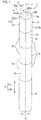
- FIG. 1 is a perspective view of a signal indicator light 1 according to a preferred embodiment of this invention as viewed from above.
- the signal indicator light 1 is installed at, for example, a manufacturing site and is used to inform surrounding people of a situation or the like of each place in the manufacturing site.
- the signal indicator light 1 is formed in, for example, a columnar shape.
- An attitude of the signal indicator light 1 at the time of use can be arbitrarily changed according to usage conditions.
- the following description will be made with reference to the signal indicator light 1 when a center axis line J of the signal indicator light 1 extends vertically. In this case, a vertical direction of a paper surface of FIG.
- the vertical direction X is also an axial direction in which the center axis line J extends in the signal indicator light 1.
- the signal indicator light 1 includes a base unit 2, an indicator unit 3 that emits light, and a buzzer unit 4 that emits buzzer sound.
- the base unit 2, the indicator unit 3 and the buzzer unit 4 are formed in a cylindrical shape having substantially the same outer diameter, and their center axis lines are coincident with the center axis line J.
- the base unit 2 is located at a lower end of the signal indicator light 1.
- a single indicator unit 3 or a plurality of the indicator units 3 is/are coupled to the base unit 2 from the upper side X1.
- the buzzer unit 4 is coupled to the indicator unit 3 from the upper side X1 so as to be located at an upper end of the signal indicator light 1.
- each of the base unit 2, the indicator unit 3, and the buzzer unit 4 will be described by using a radial direction R and a peripheral direction S centered on the center axis line J of the signal indicator light 1 and the vertical direction X.
- a radial direction R a direction approaching the center axis line J is referred to as a radial inside R1
- a direction away from the center axis line J is referred to as a radial outside R2.
- most of components other than electrical components such as a substrate or the like described later are made of resin, but materials of the signal indicator light 1 are not limited to resin.
- coupling two members means that one member is detachably attached to the other member by using an engaging structure or the like for engaging a projection of the one member with a groove in the other member, or that the one member is simply placed on the other member.
- the base unit 2 is fixed to an installation target such as a machine tool or the like at a manufacturing site.
- a power supply substrate (not shown) for supplying electric power to the indicator unit 3 and the buzzer unit 4, and a control substrate (not shown) for controlling operations of the indicator unit 3 and the buzzer unit 4 are built in the base unit 2.
- the indicator unit 3 includes a cylindrical case 5 having a light-transmitting property and a light-emitting unit 6 accommodated in the case 5.
- the light emitting unit 6 includes a substrate (not shown), a light source (not shown) such as an LED mounted on this substrate, and a lens (not shown).
- the light source When electric power is supplied to the indicator unit 3 from the power supply substrate (not shown) of the base unit 2, the light source emits light. This light passes through the lens and the case 5 and is emitted from entire area of the indicator unit 3 in the peripheral direction S toward the periphery of the indicator unit 3.
- a light emission pattern of the indicator unit 3 is controlled by the control substrate (not shown) of the base unit 2.
- each indicator unit 3 has the same form, but at least one of the case 5 and the lens in each indicator unit 3 may be colored with a different color from that of other indicator unit 3 so that emission color is different for each indicator unit 3.
- emission color of the light source may be different for each indicator unit 3.
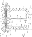
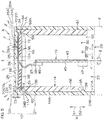
- FIG. 2 is a schematic longitudinal sectional view of the buzzer unit 4.
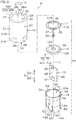
- FIG. 3 is an exploded perspective view of the buzzer unit 4.
- the buzzer unit 4 includes a cylindrical case 10, a disk-shaped vibrating element 11, an annular elastic member 12, a substrate 13, and a pressing member 14 that is cylindrical and smaller than the case 10 and accommodates the substrate 13.
- the vibrating element 11, the elastic member 12 and the pressing member 14 are accommodated in the case 10 in a state in which their center axis lines are coincident with a center axis line of the case 10. In this state, center axis lines of the case 10, the vibrating element 11, the elastic member 12 and the pressing member 14 respectively coincide with the center axis line J.
- the case 10 integrally includes a disk-shaped top plate 20 having a thickness direction which is coincident with the vertical direction X, and an annular wall 21 which is formed in a circularly annular shape and extends from entire regions in the peripheral direction S of an outer peripheral edge of the top plate 20 to the lower side X2.
- a substantially columnar storage space 22 surrounded by the top plate 20 and the annular wall 21 is formed.
- the storage space 22 is closed from the upper side X1 by the top plate 20.
- a portion surrounded by a lower end of the annular wall 21 is an opening portion 23 which exposes the storage space 22 from the case 10 to the lower side X2. Since there are no through-holes in whole regions of each of the top plate 20 and the annular wall 21, the storage space 22 is not exposed to the outside of the case 10 from portions other than the opening portion 23 of the case 10.
- the top plate 20 integrally includes a thick portion 24 formed in an annular shape (circularly annular shape in the present embodiment) extending in the peripheral direction S as an outer circumferential portion of the top plate 20, and a thin portion 25 formed in a substantially disk shape positioned radial inside R1 from the thick portion 24.
- a thickness T1 (about 1 mm, for example) of the thin portion 25 in the vertical direction X is thinner than a thickness T2 (about 2 mm, for example) of the thick portion 24 in the vertical direction X (see FIG. 2 ).
- An upper surface 24A of the thick portion 24 and an upper surface 25A of the thin portion 25 are flush with each other and constitute an outer surface 20A of the top plate 20, but a lower surface 24B of the thick portion 24 is located on the lower side X2 from a lower surface 25B of the thin portion 25. Therefore, a concave first space 26 depressed to the upper side X1 is formed in a region on a side of the center axis line J in the inner surface 20B formed by the lower surface 24B and the lower surface 25B of the top plate 20.
- the first space 26 is a part of the storage space 22 and is surrounded by the thick portion 24 from the radial outside R2.
- a communicating portion 27 is formed by cutting a part of the thick portion 24 along the radial direction R (see FIG. 3 ).
- An end portion of the radial outside R2 of the communicating portion 27 communicates with regions (the outside of the thick portion 24) other than the first space 26 in the storage space 22 from the upper side X1. Therefore, the communicating portion 27 communicates the first space 26 with the regions.
- An arbitrary configuration other than the groove shape can be adopted as the communicating portion 27.
- the communicating portion 27 may be a hole that allows the first space 26 to communicate with the regions.
- the thin portion 25 and a portion adjacent to the thin portion 25 in the thick portion 24 constitute a vibrating plate 28.
- the first space 26 is positioned on the lower side X2 which is one surface side of the vibrating plate 28 with respect to the vibrating plate 28.
- a claw-shaped first engagement portion 29 projecting to the radial inside R1 is provided at a position biased toward the lower side X2 on an inner peripheral surface 21A of the annular wall 21.
- a single first engagement portion 29 or a plurality of the first engagement portions 29 is/are present, and in the case where a plurality of the first engagement portions 29 are provided, the first engagement portions 29 are arranged with an interval in the peripheral direction S.
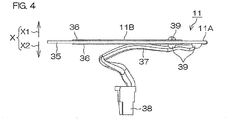
- the vibrating element 11 is formed in a flat-plate shape having a plate thickness direction coinciding with the vertical direction X.
- the vibrating element 11 has a simple configuration including a disk-shaped metal plate 35, a disk-shaped piezoelectric element 36 having a diameter which is smaller than that of the metal plate 35, an electric wire 37, and a connector 38.
- the metal plate 35 is made of iron and the piezoelectric element 36 is made of ceramics, but different materials may be used for the metal plate 35 and the piezoelectric element 36, respectively.
- a pair of the piezoelectric elements 36 are provided, and are bonded to the metal plate 35 so as to sandwich the metal plate 35 in the vertical direction X.
- One end portion of the electric wire 37 is connected to the connector 38 and the other end portion of the electric wire 37 is connected to an electrode 39 provided in each of the metal plate 35 and the piezoelectric element 36.
- An outer peripheral portion of the metal plate 35 constitutes an outer edge portion 11A of the vibrating element 11.
- the elastic member 12 is an annular sheet made of an elastic body such as urethane, sponge, rubber or the like. Therefore, the elastic member 12 has an insertion hole 12A penetrating the elastic member 12 through a central axis thereof.
- the substrate 13 has a pair of parallel main surfaces 45 extending in the vertical direction X.
- a first connector 46 is provided at an upper end portion of the substrate 13 and a second connector 47 is provided at a lower end portion of the substrate 13.
- the first connector 46 and the second connector 47 may be provided on the same main surface 45 of the substrate 13 or may be provided separately on separate main surfaces 45 respectively.
- the pressing member 14 is formed with an inner space 50 constituting a hollow portion of the pressing member 14, a first opening portion 51 opening the inner space 50 to the upper side X1, and a second opening portion 52 opening the inner space 50 to the lower side X2.
- the pressing member 14 includes an annular pressing portion 53 surrounding the first opening portion 51, and a projected line portion 54 protruding from an outer peripheral edge of an upper end surface 53A of the pressing portion 53 toward the upper side X1 and extending in the peripheral direction S.
- a plurality of the projected line portions 54 are arranged at intervals in the peripheral direction S.
- a single projected line portion 54 may be provided over entire regions of an outer peripheral edge of the pressing portion 53 in the peripheral direction S.
- claw-shaped second engagement portions 55 projecting to the radial outside R2 are provided at positions corresponding to the first engagement portions 29 in the peripheral direction S.
- the number of the second engagement portions 55 is same as the number of the first engagement portions 29.
- the pressing member 14 is formed with a notch 14B extending from a lower end edge of the pressing member 14 toward a midway portion of the pressing member 14 in the vertical direction X to the upper side X1 (see FIG. 3 ).
- the notch 14B cuts out a part of the pressing member 14 in the peripheral direction S.
- a pair of the notches 14B may be provided on both sides of the second engagement portion 55 in the peripheral direction S.
- a portion between the pair of notches 14B in the pressing member 14 constitutes an arm portion 56 extending to the lower side X2.
- the second engagement portion 55 is provided at a lower end portion of the arm portion 56.
- the arm portion 56 is elastically deformable so that the second engagement portion 55 can move along the radial direction R.
- the operator inserts the substrate 13 from the upper side X1 into the first opening portion 51 of the pressing member 14 so that a side of the second connector 47 becomes the head, and accommodates the substrate 13 in the inner space 50 of the pressing member 14.
- the outer peripheral portion 12B of the elastic member 12 is placed on the pressing portion 53 of the pressing member 14 and positioned by the projected line portion 54 from the radial outside R2, and the vibrating element 11 is placed on the elastic member 12.
- a bonding member 60 made of a double sided tape or an adhesive is provided on an upper surface and a lower surface of the outer peripheral portion 12B of the elastic member 12.
- the outer edge portion 11A of the vibrating element 11 is bonded to an upper surface of the outer peripheral portion 12B of the elastic member 12, and the upper end surface 53A of the pressing portion 53 is bonded to a lower surface of the outer peripheral portion 12B of the elastic member 12.
- the vibrating element 11, the elastic member 12, the substrate 13 and the pressing member 14 integrated in this way constitute an inner assembly 61.
- the substrate 13 is held in the inner space 50 by being engaged with an engagement portion (not shown) provided at the pressing member 14.
- the operator places the completed inner assembly 61 on the lower side X2 of the case 10 and inserts the inner assembly 61 from the lower side X2 with respect to the opening portion 23 of the case 10 so that the vibrating element 11 becomes the head.
- the entire inner assembly 61 is accommodated in the storage space 22 of the case 10.
- the second engagement portion 55 of the pressing member 14 climbs over the first engagement portion 29 of the case 10 to the upper side X1 and engages with the first engagement portion 29 from the upper side X1
- the inner assembly 61 in the storage space 22 is in a state of being fixed to the case 10.
- the buzzer unit 4 is completed.
- the vibrating element 11 in the storage space 22 is opposed to the top plate 20 of the case 10 from the lower side X2. More specifically, in the vibrating element 11, the outer edge portion 11A is opposed to the thick portion 24 of the top plate 20, that is, an outer edge portion of the vibrating plate 28 from the lower side X2, and an inner portion 11B surrounded by the outer edge portion 11A in the vibrating element 11 is opposed to the thin portion 25 of the top plate 20, that is, an inner portion of the vibrating plate 28 from the lower side X2.
- a bonding member 65 made of a double sided tape or an adhesive is provided on an upper surface of the outer edge portion 11A in advance. Thereby, at least the outer edge portion 11A is bonded to the thick portion 24.
- the vibrating element 11 can be easily fixed to the top plate 20 by the bonding member 65.
- the first space 26 provided on the inner surface 20B of the top plate 20 is sandwiched and closed from the vertical direction X by the thin portion 25 and the inner portion 11B, and is communicated with other regions (regions on the lower side X2 than the first space 26 in the inner space 50) from only the communicating portion 27.
- a gap 68 in the vertical direction X between the thick portion 24 and the pressing portion 53 of the pressing member 14 is one of communication paths for communicating the first space 26 with the other regions.
- the pressing portion 53 is opposed to the outer edge portion 11A of the vibrating element 11 from the lower side X2.
- the outer peripheral portion 12B of the elastic member 12 is disposed in a compressed state while being sandwiched from the vertical direction X by the outer edge portion 11A and the pressing portion 53.
- the outer peripheral portion 12B of the elastic member 12 tries to return to a state before being compressed, thereby is always urging the vibrating element 11 toward the vibrating plate 28 (more specifically, the thick portion 24) on the upper side X1. That is, the pressing portion 53 compresses the elastic member 12, thereby is pressing the vibrating element 11 against the thick portion 24 of the vibration plate 28.
- a second space 66 surrounded by the pressing portion 53 is formed on a lower side X2 which is an opposite side to the vibration plate 28 with respect to the vibrating element 11.
- the second space 66 is a part of the storage space 22 and adjoins the elastic member 12 from the lower side X2.
- the signal indicator light 1 is completed.
- An upper end surface 1A which is one end surface of the completed signal indicator light 1 in the vertical direction X is constituted by the outer surface 20A of the top plate 20 of the case 10 of the buzzer unit 4 (see FIG. 1 ). Therefore, the upper end surface 1A includes a surface 28A of the vibrating plate 28 exposed outside. Additionally, in the completed signal indicator light 1, since the opening portion 23 of the case 10 of the buzzer unit 4 is closed by the indicator unit 3 from the lower side X2, the storage space 22 of the case 10 is completely sealed.
- the second connector 47 of the substrate 13 of the buzzer unit 4 is connected to a connector (not shown) provided on a substrate (not shown) of the indicator unit 3.
- the substrate 13 is electrically connected to the power supply substrate (not shown) and the control substrate (not shown) in the base unit 2 via the substrate of the indicator unit 3.
- voltage is applied to the vibrating element 11.
- the piezoelectric element 36 expands and contracts, and expansion and contraction thereof is transmitted to the metal plate 35, whereby the metal plate 35 alternately bends to the upper side X1 and the lower side X2.
- the entire vibrating element 11 (in particular, the inner portion 11B) vibrates in the vertical direction X.
- This vibration is transmitted to the vibrating plate 28 at the thick portion 24 of the top plate 20 and/or is transmitted to the vibrating plate 28 via air in the first space 26 so that the entire vibrating plate 28 vibrates in the vertical direction X.
- sound waves are generated.
- the pressing member 14 presses the vibrating element 11 against the vibration plate 28, the degree of adhesion between the vibrating element 11 and the vibration plate 28 can be increased. Since the case 10 and the pressing member 14 are connected so as to be relatively immovable by engagement between the first engagement portion 29 and the second engagement portion 55, the pressing member 14 can reliably maintain a state that the pressing member 14 presses the vibrating element 11 against the vibration plate 28. Additionally, the vibrating element 11 is bonded to the thick portion 24 of the top plate 20 of the case 10 by the bonding member 65 and is urged toward the vibrating plate 28 by the elastic member 12. Thereby, the vibrating element 11 and the vibrating plate 28 can be disposed close to each other, and the degree of adhesion between them can be further increased.
- the vibrating plate 28 includes at least the thin portion 25 formed thinner than the thick portion 24 in the top plate 20 of the case 10, when vibration of the vibrating element 11 is transmitted, the thin portion 25 can vibrate with large amplitude. Thereby, sound pressure can be further improved.
- the value of voltage applied to the vibrating element 11 is controlled by the control substrate (not shown) of the base unit 2, whereby sound having a wide sound range from low tone to high tone can be generated.
- the buzzer unit 4 with wide directivity in particular substantially omnidirectional can be obtained. That is, the buzzer unit 4 can obtain directional characteristics which are suitable for a purpose of announcing sound over a wide range.
- there are no through-holes in the vibrating plate 28 and the storage space 22 is completely sealed it is possible to prevent intrusion of water and contaminations into the storage space 22.
- the signal indicator light 1 including such a buzzer unit 4 can improve wide directivity in the buzzer unit 4, the signal indicator light 1 can emit sound with high sound pressure to all directions (a full range of 360 degrees on the outer peripheral surface 1B) around the center axis line J (see Fig. 1 ). Additionally, since there are no through-holes in the vibrating plate 28 constituting the upper end surface 1A of the signal indicator light 1, entering of water from the upper side X1 into the signal indicator light 1 can be prevented. Therefore, the signal indicator light 1 can improve waterproofness and prevent contaminations from adhering to inside thereof.
- the vibrating element 11 which tries to move toward the vibrating plate 28 in accordance with vibration can enter the first space 26 formed on the lower side X2 of the vibrating plate 28.
- the vibrating element 11 which tries to move to the lower side X2 opposite to the vibration plate 28 according to vibration can enter the second space 66 surrounded by the pressing portion 53 of the pressing member 14. That is, a space for vibrating the vibrating element 11 is secured on both sides of the vibrating element 11 in the vertical direction X. Therefore, it is possible to prevent vibration of the vibrating element 11 in the vertical direction X from being disturbed.
- the elastic member 12 can be elastically deformed to the lower side X2 so as not to disturb movement of the vibrating element 11. Additionally, by releasing pressure in the first space 26 by the communicating portion 27 (see FIG. 3 ) formed in the thick portion 24, vibration of the vibrating element 11 and the vibration plate 28 is can be prevented from being disturbed by pressure in the first space 26.
- the vibrating element 11 only the outer edge portion 11A is pressed against the thick portion 24 of the top plate 20, but the inner portion 11B is separated from the thin portion 25 of the top plate 20. Therefore, since the inner portion 11B and the thin portion 25 of the vibrating plate 28 are not constrained to each other, each of them can vibrate with large amplitude. Sound waves generated by the vibrating element 11 are transmitted to the thin portion 25 via air in the first space 26 and vibrates the thin portion 25 with large amplitude. Since the vibrating element 11 is brought into close contact with the thick portion 24 by being pressed against the thick portion 24, vibration of the vibrating element 11 is directly transmitted from the thick portion 24 to the vibration plate 28.
- the first space 26 with constant narrowness in the vertical direction X so that the vibrating element 11 and the thin portion 25 can approach to each other in mutually non-constraint state by pressing the vibrating element 11 against the thick portion 24. Thereby, it is possible to effectively transmit sound waves generated by the vibrating element 11 to the thin portion 25. Thereby of the above, vibration of the vibrating element 11 can be transmitted to the vibrating plate 28 more efficiently so that the vibration plate 28 can be more effectively vibrated.
- a groove 70 extending in the peripheral direction S may be formed as a part of the communicating portion 27 between the thick portion 24 of the top plate 20 of the case 10 and the annular wall 21.
- the thick portion 24 may be separated from the annular wall 21 to the radial inside R1 by the groove 70. Thereby, free motion of the inner portion 11B of the vibrating element 11 can be promoted, so that the vibrating element 11 can be more effectively vibrated.
- target sound pressure of the buzzer unit 4 is set so as to exceed sound pressure of the environmental sound by about 10dB.
- the thickness T1 of the thin portion 25 of the top plate 20 of the case 10 is preferably about 0.75mm.
- the thickness T1 is preferably about 1mm.
- the buzzer unit 4 can emit large sound with high sound pressure.
- the signal indicator light 1 may be, for example, a quadrangular columnar shape instead of a cylindrical shape.
- the pressing member 14 may indirectly hold the substrate 13 by the substrate 13 engaged to another member disposed in the inner space 50 of the pressing member 14.
- an electric actuator such as a motor or a solenoid may be used as the vibrating element 11.
- the vibrating element 11 may have a unimorph type configuration in which the piezoelectric element 36 is attached only on one side surface of the metal plate 35, instead of a bimorph type configuration in which the metal plate 35 is sandwiched between the pair of piezoelectric elements 36 as described above, for example.
- the unimorph type vibrating element 11 in which the piezoelectric element 36 is attached only to a lower surface of the metal plate 35, upper surfaces of both the outer edge portion 11A and the inner portion 11B of the vibrating element 11 may be brought into close contact with the top plate 20. In this case, the first space 26 in the inner surface 20B of the top plate 20 is omitted.
- the signal indicator light 1 may include a communication unit with a communication function for communicating with an external device, in addition to the indicator unit 3.
- a rotating lamp may be used as the indicator unit 3.
Landscapes
- Physics & Mathematics (AREA)
- Engineering & Computer Science (AREA)
- General Physics & Mathematics (AREA)
- Acoustics & Sound (AREA)
- Multimedia (AREA)
- Electromagnetism (AREA)
- Mechanical Engineering (AREA)
- Piezo-Electric Transducers For Audible Bands (AREA)
Applications Claiming Priority (1)
| Application Number | Priority Date | Filing Date | Title |
|---|---|---|---|
| PCT/JP2016/051893 WO2017126114A1 (fr) | 2016-01-22 | 2016-01-22 | Unité d'avertisseur et voyant d'indicateur de signal |
Publications (3)
| Publication Number | Publication Date |
|---|---|
| EP3407346A1 true EP3407346A1 (fr) | 2018-11-28 |
| EP3407346A4 EP3407346A4 (fr) | 2019-08-21 |
| EP3407346B1 EP3407346B1 (fr) | 2020-09-02 |
Family
ID=59362514
Family Applications (1)
| Application Number | Title | Priority Date | Filing Date |
|---|---|---|---|
| EP16886355.3A Active EP3407346B1 (fr) | 2016-01-22 | 2016-01-22 | Unité d'avertisseur et voyant d'indicateur de signal |
Country Status (6)
| Country | Link |
|---|---|
| US (1) | US10297243B2 (fr) |
| EP (1) | EP3407346B1 (fr) |
| JP (1) | JP6548050B2 (fr) |
| KR (1) | KR102089999B1 (fr) |
| CN (1) | CN107851428B (fr) |
| WO (1) | WO2017126114A1 (fr) |
Families Citing this family (3)
| Publication number | Priority date | Publication date | Assignee | Title |
|---|---|---|---|---|
| CN111326133A (zh) * | 2018-12-17 | 2020-06-23 | 海湾安全技术有限公司 | 蜂鸣器、蜂鸣装置以及安防设备 |
| CN114267142A (zh) * | 2020-09-16 | 2022-04-01 | 青鸟消防股份有限公司 | 火灾声光警报器 |
| CN112581926B (zh) * | 2020-12-15 | 2022-03-11 | 新沂市承翔电子有限公司 | 一种防护性能高的电子蜂鸣器 |
Family Cites Families (20)
| Publication number | Priority date | Publication date | Assignee | Title |
|---|---|---|---|---|
| JPS5838719Y2 (ja) * | 1978-09-07 | 1983-09-01 | 株式会社村田製作所 | 圧電ブザ− |
| JPS6243360Y2 (fr) * | 1979-01-18 | 1987-11-10 | ||
| JPS5765092A (en) | 1980-10-09 | 1982-04-20 | Seiko Instr & Electronics Ltd | Microphone in common use with speaker |
| US4641054A (en) | 1984-08-09 | 1987-02-03 | Nippon Ceramic Company, Limited | Piezoelectric electro-acoustic transducer |
| JPS6137698U (ja) * | 1984-08-09 | 1986-03-08 | 株式会社 日東 | 圧電振動装置 |
| US4810997A (en) * | 1986-03-20 | 1989-03-07 | Kabushiki Kaisha Sankyo Seiki Seisakusho | Small sound generating device |
| JPS6484512A (en) * | 1987-09-28 | 1989-03-29 | Nippon Yakin Kogyo Co Ltd | Loudspeaker serving as lighting apparatus |
| DE68919100T2 (de) * | 1988-03-17 | 1995-03-09 | Tdk Corp | Piezoelektrischer Summer und Verfahren zu dessen Herstellung. |
| JPH05145983A (ja) | 1991-11-22 | 1993-06-11 | Karasawamakoto Kenchiku Onkyo Sekkei Jimusho:Kk | スピーカ装置 |
| US5378880A (en) * | 1993-08-20 | 1995-01-03 | Indala Corporation | Housing structure for an access control RFID reader |
| JP3311519B2 (ja) * | 1994-10-25 | 2002-08-05 | ティーディーケイ株式会社 | 圧電サウンダ |
| US5822403A (en) * | 1996-08-21 | 1998-10-13 | Rowan; James | Automated telephone hold device |
| JPH1152958A (ja) | 1997-08-05 | 1999-02-26 | Murata Mfg Co Ltd | 圧電型電気音響変換器 |
| JP4124770B2 (ja) | 2005-01-28 | 2008-07-23 | Tdk株式会社 | 圧電サウンダ |
| JP5152557B2 (ja) | 2007-07-03 | 2013-02-27 | 株式会社パトライト | 音響報知ユニット及びそれを用いた信号表示灯 |
| US7728716B2 (en) * | 2007-08-01 | 2010-06-01 | China Steel Corporation | Piezoelectric buzzer |
| JPWO2009110575A1 (ja) * | 2008-03-07 | 2011-07-14 | 日本電気株式会社 | 圧電アクチュエータ及び電子機器 |
| CN201643597U (zh) * | 2009-09-24 | 2010-11-24 | 展洪胜 | 声光互动的打击装置 |
| WO2013038343A1 (fr) * | 2011-09-13 | 2013-03-21 | University Of The Free State | Indicateur de haute tension |
| CN202598211U (zh) * | 2012-04-26 | 2012-12-12 | 浙江众谊达光电科技有限公司 | 一种新型多色彩led警示灯 |
-
2016
- 2016-01-22 KR KR1020177036433A patent/KR102089999B1/ko active Active
- 2016-01-22 CN CN201680040743.9A patent/CN107851428B/zh active Active
- 2016-01-22 US US15/740,642 patent/US10297243B2/en active Active
- 2016-01-22 WO PCT/JP2016/051893 patent/WO2017126114A1/fr not_active Ceased
- 2016-01-22 EP EP16886355.3A patent/EP3407346B1/fr active Active
- 2016-01-22 JP JP2017510922A patent/JP6548050B2/ja active Active
Also Published As
| Publication number | Publication date |
|---|---|
| US20180197521A1 (en) | 2018-07-12 |
| CN107851428B (zh) | 2022-08-19 |
| CN107851428A (zh) | 2018-03-27 |
| JPWO2017126114A1 (ja) | 2018-11-08 |
| EP3407346A4 (fr) | 2019-08-21 |
| EP3407346B1 (fr) | 2020-09-02 |
| JP6548050B2 (ja) | 2019-07-24 |
| KR102089999B1 (ko) | 2020-03-17 |
| WO2017126114A1 (fr) | 2017-07-27 |
| US10297243B2 (en) | 2019-05-21 |
| KR20180109044A (ko) | 2018-10-05 |
Similar Documents
| Publication | Publication Date | Title |
|---|---|---|
| US9503805B2 (en) | Piezoelectric ceramic dual-frequency earphone structure | |
| JP6883223B2 (ja) | スピーカー装置 | |
| US10297243B2 (en) | Buzzer unit and signal indicator light | |
| US10779077B2 (en) | Microphone cavity | |
| JPS60134700A (ja) | 発音装置 | |
| KR102010926B1 (ko) | 패널 가진형 스피커 | |
| WO2016067707A1 (fr) | Dispositif de production sonore | |
| JP2009278214A (ja) | 電気音響変換器 | |
| JP4124770B2 (ja) | 圧電サウンダ | |
| WO2016103930A1 (fr) | Dispositif de haut-parleur | |
| KR100427101B1 (ko) | 다기능형 발음체와 휴대 단말기 | |
| CN107305766B (zh) | 光与声信号装置 | |
| EP3407129A1 (fr) | Appareil électronique avec microphone et émetteur de lumière | |
| US4321699A (en) | Wrist watch with alarm | |
| KR100413603B1 (ko) | 이동통신 단말기의 마그네틱 버저 설치구조 | |
| JP3562383B2 (ja) | スピーカ | |
| KR102433620B1 (ko) | 선형 스피커 | |
| JP6692892B2 (ja) | ハウジングおよびこのハウジングに配置されたダイヤフラムエレメントを有する音響センサ | |
| JP2019164173A (ja) | 発音装置、及びそれを備えた感知器 | |
| CN222381792U (zh) | 振动发声装置、振动发声模组和电子终端 | |
| JP2021024323A (ja) | 発音器の取付構造および発音器を取り付けた車両 | |
| JPH10136481A (ja) | 電子機器の報音部構造 | |
| JP2005094572A (ja) | ピエゾスピーカー | |
| JP3868851B2 (ja) | 電気音響変換器 | |
| CN118574062A (zh) | 振动发声装置、振动发声模组、振动发声模组的装配方法和电子终端 |
Legal Events
| Date | Code | Title | Description |
|---|---|---|---|
| STAA | Information on the status of an ep patent application or granted ep patent |
Free format text: STATUS: THE INTERNATIONAL PUBLICATION HAS BEEN MADE |
|
| PUAI | Public reference made under article 153(3) epc to a published international application that has entered the european phase |
Free format text: ORIGINAL CODE: 0009012 |
|
| STAA | Information on the status of an ep patent application or granted ep patent |
Free format text: STATUS: REQUEST FOR EXAMINATION WAS MADE |
|
| 17P | Request for examination filed |
Effective date: 20180104 |
|
| AK | Designated contracting states |
Kind code of ref document: A1 Designated state(s): AL AT BE BG CH CY CZ DE DK EE ES FI FR GB GR HR HU IE IS IT LI LT LU LV MC MK MT NL NO PL PT RO RS SE SI SK SM TR |
|
| AX | Request for extension of the european patent |
Extension state: BA ME |
|
| DAV | Request for validation of the european patent (deleted) | ||
| DAX | Request for extension of the european patent (deleted) | ||
| A4 | Supplementary search report drawn up and despatched |
Effective date: 20190723 |
|
| RIC1 | Information provided on ipc code assigned before grant |
Ipc: G08B 3/10 20060101ALI20190717BHEP Ipc: G08B 7/06 20060101ALI20190717BHEP Ipc: H01L 41/08 20060101ALI20190717BHEP Ipc: B06B 1/06 20060101ALI20190717BHEP Ipc: H01L 41/09 20060101ALI20190717BHEP Ipc: G10K 9/22 20060101ALI20190717BHEP Ipc: G10K 9/122 20060101AFI20190717BHEP |
|
| REG | Reference to a national code |
Ref country code: DE Ref legal event code: R079 Ref document number: 602016043503 Country of ref document: DE Free format text: PREVIOUS MAIN CLASS: G10K0009122000 Ipc: B06B0001060000 |
|
| GRAP | Despatch of communication of intention to grant a patent |
Free format text: ORIGINAL CODE: EPIDOSNIGR1 |
|
| STAA | Information on the status of an ep patent application or granted ep patent |
Free format text: STATUS: GRANT OF PATENT IS INTENDED |
|
| RIC1 | Information provided on ipc code assigned before grant |
Ipc: G10K 9/122 20060101ALI20200303BHEP Ipc: G08B 7/06 20060101ALI20200303BHEP Ipc: G10K 9/22 20060101ALI20200303BHEP Ipc: H01L 41/09 20060101ALN20200303BHEP Ipc: B06B 1/06 20060101AFI20200303BHEP Ipc: G08B 3/10 20060101ALI20200303BHEP |
|
| RIC1 | Information provided on ipc code assigned before grant |
Ipc: G08B 7/06 20060101ALI20200306BHEP Ipc: G10K 9/122 20060101ALI20200306BHEP Ipc: B06B 1/06 20060101AFI20200306BHEP Ipc: H01L 41/09 20060101ALN20200306BHEP Ipc: G10K 9/22 20060101ALI20200306BHEP Ipc: G08B 3/10 20060101ALI20200306BHEP |
|
| INTG | Intention to grant announced |
Effective date: 20200326 |
|
| GRAS | Grant fee paid |
Free format text: ORIGINAL CODE: EPIDOSNIGR3 |
|
| GRAA | (expected) grant |
Free format text: ORIGINAL CODE: 0009210 |
|
| STAA | Information on the status of an ep patent application or granted ep patent |
Free format text: STATUS: THE PATENT HAS BEEN GRANTED |
|
| AK | Designated contracting states |
Kind code of ref document: B1 Designated state(s): AL AT BE BG CH CY CZ DE DK EE ES FI FR GB GR HR HU IE IS IT LI LT LU LV MC MK MT NL NO PL PT RO RS SE SI SK SM TR |
|
| REG | Reference to a national code |
Ref country code: GB Ref legal event code: FG4D |
|
| REG | Reference to a national code |
Ref country code: AT Ref legal event code: REF Ref document number: 1308230 Country of ref document: AT Kind code of ref document: T Effective date: 20200915 Ref country code: CH Ref legal event code: EP |
|
| REG | Reference to a national code |
Ref country code: DE Ref legal event code: R096 Ref document number: 602016043503 Country of ref document: DE |
|
| REG | Reference to a national code |
Ref country code: IE Ref legal event code: FG4D |
|
| REG | Reference to a national code |
Ref country code: LT Ref legal event code: MG4D |
|
| PG25 | Lapsed in a contracting state [announced via postgrant information from national office to epo] |
Ref country code: BG Free format text: LAPSE BECAUSE OF FAILURE TO SUBMIT A TRANSLATION OF THE DESCRIPTION OR TO PAY THE FEE WITHIN THE PRESCRIBED TIME-LIMIT Effective date: 20201202 Ref country code: NO Free format text: LAPSE BECAUSE OF FAILURE TO SUBMIT A TRANSLATION OF THE DESCRIPTION OR TO PAY THE FEE WITHIN THE PRESCRIBED TIME-LIMIT Effective date: 20201202 Ref country code: GR Free format text: LAPSE BECAUSE OF FAILURE TO SUBMIT A TRANSLATION OF THE DESCRIPTION OR TO PAY THE FEE WITHIN THE PRESCRIBED TIME-LIMIT Effective date: 20201203 Ref country code: HR Free format text: LAPSE BECAUSE OF FAILURE TO SUBMIT A TRANSLATION OF THE DESCRIPTION OR TO PAY THE FEE WITHIN THE PRESCRIBED TIME-LIMIT Effective date: 20200902 Ref country code: SE Free format text: LAPSE BECAUSE OF FAILURE TO SUBMIT A TRANSLATION OF THE DESCRIPTION OR TO PAY THE FEE WITHIN THE PRESCRIBED TIME-LIMIT Effective date: 20200902 Ref country code: FI Free format text: LAPSE BECAUSE OF FAILURE TO SUBMIT A TRANSLATION OF THE DESCRIPTION OR TO PAY THE FEE WITHIN THE PRESCRIBED TIME-LIMIT Effective date: 20200902 Ref country code: LT Free format text: LAPSE BECAUSE OF FAILURE TO SUBMIT A TRANSLATION OF THE DESCRIPTION OR TO PAY THE FEE WITHIN THE PRESCRIBED TIME-LIMIT Effective date: 20200902 |
|
| REG | Reference to a national code |
Ref country code: NL Ref legal event code: MP Effective date: 20200902 |
|
| REG | Reference to a national code |
Ref country code: AT Ref legal event code: MK05 Ref document number: 1308230 Country of ref document: AT Kind code of ref document: T Effective date: 20200902 |
|
| PG25 | Lapsed in a contracting state [announced via postgrant information from national office to epo] |
Ref country code: LV Free format text: LAPSE BECAUSE OF FAILURE TO SUBMIT A TRANSLATION OF THE DESCRIPTION OR TO PAY THE FEE WITHIN THE PRESCRIBED TIME-LIMIT Effective date: 20200902 Ref country code: RS Free format text: LAPSE BECAUSE OF FAILURE TO SUBMIT A TRANSLATION OF THE DESCRIPTION OR TO PAY THE FEE WITHIN THE PRESCRIBED TIME-LIMIT Effective date: 20200902 Ref country code: PL Free format text: LAPSE BECAUSE OF FAILURE TO SUBMIT A TRANSLATION OF THE DESCRIPTION OR TO PAY THE FEE WITHIN THE PRESCRIBED TIME-LIMIT Effective date: 20200902 |
|
| PG25 | Lapsed in a contracting state [announced via postgrant information from national office to epo] |
Ref country code: PT Free format text: LAPSE BECAUSE OF FAILURE TO SUBMIT A TRANSLATION OF THE DESCRIPTION OR TO PAY THE FEE WITHIN THE PRESCRIBED TIME-LIMIT Effective date: 20210104 Ref country code: RO Free format text: LAPSE BECAUSE OF FAILURE TO SUBMIT A TRANSLATION OF THE DESCRIPTION OR TO PAY THE FEE WITHIN THE PRESCRIBED TIME-LIMIT Effective date: 20200902 Ref country code: CZ Free format text: LAPSE BECAUSE OF FAILURE TO SUBMIT A TRANSLATION OF THE DESCRIPTION OR TO PAY THE FEE WITHIN THE PRESCRIBED TIME-LIMIT Effective date: 20200902 Ref country code: EE Free format text: LAPSE BECAUSE OF FAILURE TO SUBMIT A TRANSLATION OF THE DESCRIPTION OR TO PAY THE FEE WITHIN THE PRESCRIBED TIME-LIMIT Effective date: 20200902 Ref country code: SM Free format text: LAPSE BECAUSE OF FAILURE TO SUBMIT A TRANSLATION OF THE DESCRIPTION OR TO PAY THE FEE WITHIN THE PRESCRIBED TIME-LIMIT Effective date: 20200902 |
|
| PG25 | Lapsed in a contracting state [announced via postgrant information from national office to epo] |
Ref country code: ES Free format text: LAPSE BECAUSE OF FAILURE TO SUBMIT A TRANSLATION OF THE DESCRIPTION OR TO PAY THE FEE WITHIN THE PRESCRIBED TIME-LIMIT Effective date: 20200902 Ref country code: AT Free format text: LAPSE BECAUSE OF FAILURE TO SUBMIT A TRANSLATION OF THE DESCRIPTION OR TO PAY THE FEE WITHIN THE PRESCRIBED TIME-LIMIT Effective date: 20200902 Ref country code: AL Free format text: LAPSE BECAUSE OF FAILURE TO SUBMIT A TRANSLATION OF THE DESCRIPTION OR TO PAY THE FEE WITHIN THE PRESCRIBED TIME-LIMIT Effective date: 20200902 Ref country code: IS Free format text: LAPSE BECAUSE OF FAILURE TO SUBMIT A TRANSLATION OF THE DESCRIPTION OR TO PAY THE FEE WITHIN THE PRESCRIBED TIME-LIMIT Effective date: 20210102 |
|
| REG | Reference to a national code |
Ref country code: DE Ref legal event code: R097 Ref document number: 602016043503 Country of ref document: DE |
|
| PG25 | Lapsed in a contracting state [announced via postgrant information from national office to epo] |
Ref country code: SK Free format text: LAPSE BECAUSE OF FAILURE TO SUBMIT A TRANSLATION OF THE DESCRIPTION OR TO PAY THE FEE WITHIN THE PRESCRIBED TIME-LIMIT Effective date: 20200902 |
|
| PLBE | No opposition filed within time limit |
Free format text: ORIGINAL CODE: 0009261 |
|
| STAA | Information on the status of an ep patent application or granted ep patent |
Free format text: STATUS: NO OPPOSITION FILED WITHIN TIME LIMIT |
|
| 26N | No opposition filed |
Effective date: 20210603 |
|
| PG25 | Lapsed in a contracting state [announced via postgrant information from national office to epo] |
Ref country code: SI Free format text: LAPSE BECAUSE OF FAILURE TO SUBMIT A TRANSLATION OF THE DESCRIPTION OR TO PAY THE FEE WITHIN THE PRESCRIBED TIME-LIMIT Effective date: 20200902 Ref country code: DK Free format text: LAPSE BECAUSE OF FAILURE TO SUBMIT A TRANSLATION OF THE DESCRIPTION OR TO PAY THE FEE WITHIN THE PRESCRIBED TIME-LIMIT Effective date: 20200902 Ref country code: MC Free format text: LAPSE BECAUSE OF FAILURE TO SUBMIT A TRANSLATION OF THE DESCRIPTION OR TO PAY THE FEE WITHIN THE PRESCRIBED TIME-LIMIT Effective date: 20200902 |
|
| REG | Reference to a national code |
Ref country code: CH Ref legal event code: PL |
|
| GBPC | Gb: european patent ceased through non-payment of renewal fee |
Effective date: 20210122 |
|
| PG25 | Lapsed in a contracting state [announced via postgrant information from national office to epo] |
Ref country code: LU Free format text: LAPSE BECAUSE OF NON-PAYMENT OF DUE FEES Effective date: 20210122 |
|
| REG | Reference to a national code |
Ref country code: BE Ref legal event code: MM Effective date: 20210131 |
|
| PG25 | Lapsed in a contracting state [announced via postgrant information from national office to epo] |
Ref country code: IT Free format text: LAPSE BECAUSE OF FAILURE TO SUBMIT A TRANSLATION OF THE DESCRIPTION OR TO PAY THE FEE WITHIN THE PRESCRIBED TIME-LIMIT Effective date: 20200902 Ref country code: FR Free format text: LAPSE BECAUSE OF NON-PAYMENT OF DUE FEES Effective date: 20210131 |
|
| PG25 | Lapsed in a contracting state [announced via postgrant information from national office to epo] |
Ref country code: LI Free format text: LAPSE BECAUSE OF NON-PAYMENT OF DUE FEES Effective date: 20210131 Ref country code: GB Free format text: LAPSE BECAUSE OF NON-PAYMENT OF DUE FEES Effective date: 20210122 Ref country code: CH Free format text: LAPSE BECAUSE OF NON-PAYMENT OF DUE FEES Effective date: 20210131 |
|
| PG25 | Lapsed in a contracting state [announced via postgrant information from national office to epo] |
Ref country code: IE Free format text: LAPSE BECAUSE OF NON-PAYMENT OF DUE FEES Effective date: 20210122 |
|
| PG25 | Lapsed in a contracting state [announced via postgrant information from national office to epo] |
Ref country code: IS Free format text: LAPSE BECAUSE OF FAILURE TO SUBMIT A TRANSLATION OF THE DESCRIPTION OR TO PAY THE FEE WITHIN THE PRESCRIBED TIME-LIMIT Effective date: 20210102 |
|
| PG25 | Lapsed in a contracting state [announced via postgrant information from national office to epo] |
Ref country code: BE Free format text: LAPSE BECAUSE OF NON-PAYMENT OF DUE FEES Effective date: 20210131 |
|
| P01 | Opt-out of the competence of the unified patent court (upc) registered |
Effective date: 20230321 |
|
| PG25 | Lapsed in a contracting state [announced via postgrant information from national office to epo] |
Ref country code: NL Free format text: LAPSE BECAUSE OF NON-PAYMENT OF DUE FEES Effective date: 20200923 Ref country code: CY Free format text: LAPSE BECAUSE OF FAILURE TO SUBMIT A TRANSLATION OF THE DESCRIPTION OR TO PAY THE FEE WITHIN THE PRESCRIBED TIME-LIMIT Effective date: 20200902 |
|
| PG25 | Lapsed in a contracting state [announced via postgrant information from national office to epo] |
Ref country code: HU Free format text: LAPSE BECAUSE OF FAILURE TO SUBMIT A TRANSLATION OF THE DESCRIPTION OR TO PAY THE FEE WITHIN THE PRESCRIBED TIME-LIMIT; INVALID AB INITIO Effective date: 20160122 |
|
| PG25 | Lapsed in a contracting state [announced via postgrant information from national office to epo] |
Ref country code: MK Free format text: LAPSE BECAUSE OF FAILURE TO SUBMIT A TRANSLATION OF THE DESCRIPTION OR TO PAY THE FEE WITHIN THE PRESCRIBED TIME-LIMIT Effective date: 20200902 |
|
| PG25 | Lapsed in a contracting state [announced via postgrant information from national office to epo] |
Ref country code: TR Free format text: LAPSE BECAUSE OF FAILURE TO SUBMIT A TRANSLATION OF THE DESCRIPTION OR TO PAY THE FEE WITHIN THE PRESCRIBED TIME-LIMIT Effective date: 20200902 |
|
| PG25 | Lapsed in a contracting state [announced via postgrant information from national office to epo] |
Ref country code: MT Free format text: LAPSE BECAUSE OF FAILURE TO SUBMIT A TRANSLATION OF THE DESCRIPTION OR TO PAY THE FEE WITHIN THE PRESCRIBED TIME-LIMIT Effective date: 20200902 |
|
| PGFP | Annual fee paid to national office [announced via postgrant information from national office to epo] |
Ref country code: DE Payment date: 20260127 Year of fee payment: 11 |