EP3407372B1 - Dispositif de relais - Google Patents
Dispositif de relais Download PDFInfo
- Publication number
- EP3407372B1 EP3407372B1 EP16886608.5A EP16886608A EP3407372B1 EP 3407372 B1 EP3407372 B1 EP 3407372B1 EP 16886608 A EP16886608 A EP 16886608A EP 3407372 B1 EP3407372 B1 EP 3407372B1
- Authority
- EP
- European Patent Office
- Prior art keywords
- mover
- contact
- contact surface
- stator
- relay apparatus
- Prior art date
- Legal status (The legal status is an assumption and is not a legal conclusion. Google has not performed a legal analysis and makes no representation as to the accuracy of the status listed.)
- Active
Links
Images


Classifications
-
- H—ELECTRICITY
- H01—ELECTRIC ELEMENTS
- H01H—ELECTRIC SWITCHES; RELAYS; SELECTORS; EMERGENCY PROTECTIVE DEVICES
- H01H50/00—Details of electromagnetic relays
- H01H50/54—Contact arrangements
- H01H50/60—Contact arrangements moving contact being rigidly combined with movable part of magnetic circuit
-
- H—ELECTRICITY
- H01—ELECTRIC ELEMENTS
- H01H—ELECTRIC SWITCHES; RELAYS; SELECTORS; EMERGENCY PROTECTIVE DEVICES
- H01H1/00—Contacts
- H01H1/06—Contacts characterised by the shape or structure of the contact-making surface, e.g. grooved
-
- H—ELECTRICITY
- H01—ELECTRIC ELEMENTS
- H01H—ELECTRIC SWITCHES; RELAYS; SELECTORS; EMERGENCY PROTECTIVE DEVICES
- H01H1/00—Contacts
- H01H1/12—Contacts characterised by the manner in which co-operating contacts engage
- H01H1/14—Contacts characterised by the manner in which co-operating contacts engage by abutting
- H01H1/20—Bridging contacts
- H01H1/2083—Bridging contact surfaces directed at an oblique angle with respect to the movement of the bridge
-
- H—ELECTRICITY
- H01—ELECTRIC ELEMENTS
- H01H—ELECTRIC SWITCHES; RELAYS; SELECTORS; EMERGENCY PROTECTIVE DEVICES
- H01H50/00—Details of electromagnetic relays
- H01H50/16—Magnetic circuit arrangements
- H01H50/18—Movable parts of magnetic circuits, e.g. armature
-
- H—ELECTRICITY
- H01—ELECTRIC ELEMENTS
- H01H—ELECTRIC SWITCHES; RELAYS; SELECTORS; EMERGENCY PROTECTIVE DEVICES
- H01H50/00—Details of electromagnetic relays
- H01H50/16—Magnetic circuit arrangements
- H01H50/36—Stationary parts of magnetic circuit, e.g. yoke
-
- H—ELECTRICITY
- H01—ELECTRIC ELEMENTS
- H01H—ELECTRIC SWITCHES; RELAYS; SELECTORS; EMERGENCY PROTECTIVE DEVICES
- H01H50/00—Details of electromagnetic relays
- H01H50/64—Driving arrangements between movable part of magnetic circuit and contact
-
- H—ELECTRICITY
- H01—ELECTRIC ELEMENTS
- H01H—ELECTRIC SWITCHES; RELAYS; SELECTORS; EMERGENCY PROTECTIVE DEVICES
- H01H50/00—Details of electromagnetic relays
- H01H50/54—Contact arrangements
- H01H50/546—Contact arrangements for contactors having bridging contacts
-
- H—ELECTRICITY
- H01—ELECTRIC ELEMENTS
- H01H—ELECTRIC SWITCHES; RELAYS; SELECTORS; EMERGENCY PROTECTIVE DEVICES
- H01H51/00—Electromagnetic relays
- H01H51/02—Non-polarised relays
- H01H51/04—Non-polarised relays with single armature; with single set of ganged armatures
- H01H51/06—Armature is movable between two limit positions of rest and is moved in one direction due to energisation of an electromagnet and after the electromagnet is de-energised is returned by energy stored during the movement in the first direction, e.g. by using a spring, by using a permanent magnet, by gravity
- H01H51/065—Relays having a pair of normally open contacts rigidly fixed to a magnetic core movable along the axis of a solenoid, e.g. relays for starting automobiles
Definitions
- the present invention relates to a relay apparatus, and more particularly, to a relay apparatus used for opening or closing an electrical circuit.
- a relay apparatus is an apparatus with an electrical contact point configured to connect or disconnect a current, and is installed in various machines or vehicles to allow any device to be automatically controlled without requiring a person to operate the device as needed.
- Examples of such relay apparatuses include polar type relays and sliding type relays.
- the polar type relay is a relay apparatus which operates by switching vertically with respect to an electromagnet to provide switchable contact points.
- Polar type relay apparatuses include a unipolar type relay having only ON and OFF functions, and a bipolar type relay which allows a switching operation to be selectively performed.
- a relay apparatus which is mainly used in mechanical and electrical devices such as automobiles is a unipolar type relay.
- Such a relay apparatus basically includes an electromagnet, an electric armature, a mover operated in conjunction with the electric armature, a stator provided to be in contact with the mover, or the like, and is operated in such a way that when a current is supplied to a coil of the electromagnet, the electric armature is pulled to mechanically move the mover so that the mover comes into contact with the stator, which becomes an ON or OFF position of the relay apparatus.
- JP 2012 199117 A relates to a contact apparatus and an electromagnetic switch apparatus using the contact apparatus.
- the contact apparatus comprises stationary contacts and moveable contacts.
- the surface of the stationary contact (1A) corresponding to the moveable contact (3A) has a flat surface.
- the surface of the moveable contact (3A) is a convex curve which protrudes towards the corresponding stationary contact (1A).
- the present invention is directed to providing a relay apparatus with an improved structure to improve contact stability between a stator and a mover.
- the present invention provides a relay apparatus including: a stator having a first fixed contact point and a second fixed contact point provided to be spaced apart from each other; a mover movably provided in a first direction which is a direction close to the stator or in a second direction which is a direction far from the stator, and electrically connected to the stator by being brought into contact with the first fixed contact point and the second fixed contact point; and an actuator configured to move the mover in the first direction or the second direction, wherein the mover includes: a first mover portion on which a first contact surface provided to be in contact with the first fixed contact point is formed; and a second mover portion on which a second contact surface and a third contact surface provided to be in contact with the second fixed contact point are formed, and the second contact surface and the third contact surface are brought into contact with the second fixed contact point at different positions.
- the first contact surface is formed on the first mover portion to form a plane surface parallel to the first fixed contact point
- the second contact surface and the third contact surface is formed on the second mover portion to form an inclined oblique surface with respect to the second fixed contact point and a central boundary is formed at a boundary portion between the second contact surface and the third contact surface by a press manufacturing process, and the central boundary forms a plane surface connecting the second contact surface and the third contact surface.
- Each of the second contact surface and the third contact surface may be linearly symmetrical about an imaginary line separating the second contact surface and the third contact surface, and may be formed to be inclined upwardly toward an end of the mover in a width direction.
- the stator and the mover may be electrically connected to each other in a form of three-point contact in which the first contact surface is brought into contact with the first fixed contact point and each of the second contact surface and the third contact surface is brought into contact with the second fixed contact point
- contact stability between a stator and a mover can be effectively improved to reduce contact heat generation, and a shape of the mover can be processed through a press process for easy manufacturing of the apparatus by increasing the number of contact points between the stator and the mover by merely changing the shape of the mover without changing the shape of the stator.
- the present invention can effectively improve the contact stability between the stator and the mover by merely changing the shape of the mover without increasing sizes of the stator and the mover, so that a relay apparatus with high contact stability can be provided while a size of the apparatus can be reduced.
- the present invention easily manufacture the apparatus by processing the shape of the mover through the press process, but can also provide improved productivity by reducing a risk in which processing defects are generated in the press process.
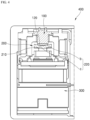
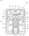
- FIG. 1 is a cross-sectional view illustrating an internal structure of a relay apparatus according to an example and FIG. 2 is a cross-sectional view taken along line "II-II" of FIG. 1 .
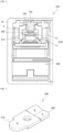
- FIG. 3 is a perspective view illustrating a mover shown in FIG. 2
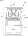
- FIG. 4 is a cross-sectional view illustrating a state in which the mover shown in FIG. 2 is moved in a first direction.
- a relay apparatus 400 includes a stator 100, a mover 200, and an actuator 300.
- the stator 100 is accommodated in a case 10 forming an exterior of the relay apparatus 400 and may be connected to a load such as a wiper motor or direction indicator of automobiles, to control the supply of power applied to the load.
- a load such as a wiper motor or direction indicator of automobiles
- a pair of stators 100 may be installed on an upper side of the case 10 to be separated from each other, and a first fixed contact point 110 and a second fixed contact point 120 are provided to be spaced apart from each other on the stators 100.
- the first fixed contact point 110 and the second fixed contact point 120 may be electrically connected to each other by being brought into contact with the mover 200, which will be described later, and may be provided in the form of an electrode made of a molybdenum (Mo) metal material.
- Mo molybdenum
- the mover 200 is provided inside the case 10 to be movable in a first direction which is a direction close to the stators 100, or in a second direction which is a direction far from the stators 100.
- the mover 200 moves in the first direction and may be electrically connected to the stators 100 by being brought into contact with the first fixed contact point 110 and the second fixed contact point 120 provided in the stators 100. Also, the mover 200 moves in the second direction and moves away from the stators 100 to allow the electrical connection with the stators 100 to be broken.
- the actuator 300 is provided inside the case 10 to move the mover 200 in the first direction or the second direction.
- the actuator 300 includes a coil 310, a fixed core 320, and a movable core 330.
- the coil 310 is installed inside the case 10 to generate a magnetic force, and the fixed core 320 is disposed inside the coil 310. Further, the movable core 330 is disposed so as to be close to and away from the fixed core 320.
- the coil 310 and the fixed core 320 are referred to as so-called electric armatures, and the movable core 330 is referred to as an armature.
- the movable core 330 and the fixed core 320 are disposed to be spaced apart from each other along a moving direction of the mover 200, that is, an axial direction which is a concept including the first direction and the second direction to which the mover 200 moves.
- the movable core 330 may be provided so as to be linearly reciprocable with respect to the fixed core 320.
- the actuator 300 may be configured so that the movable core 330 is rotatable with respect to the fixed core 320.
- the actuator 300 in which the movable core 330 is configured to be linearly reciprocable with respect to the fixed core 320 will be described.
- the above-described actuator 300 may further include a yoke 340 that forms a magnetic path together with the fixed core 320 and the movable core 330.
- the yoke 340 may include a first yoke 341 having a plate form and a second yoke 343 having an approximate U-shaped cross section.
- the fixed core 320 may be coupled to a central portion of the first yoke 341.
- the coil 310 is disposed inside the yoke 340 and typically wound around a circumference of a cylindrical bobbin 305.
- the coil 310 is connected to a coil terminal 20 for connection to a power source.
- the working rod 350 may be formed in the form of a rod having a length extending in an axial direction. Also, one end portion of the working rod 350 is connected to a center portion of the mover 200 and the other end portion of the working rod 350 is connected to the movable core 330.
- Such the working rod 350 is moved in the first direction or the second direction in conjunction with the movement of the movable core 330, and the mover 200 is moved in the first direction or the second direction by the movement of the working rod 350, and thus the stator 100 and the mover 200 may be connected or disconnected.
- the movable core 330 moves instantaneously toward the fixed core 320, that is, toward a direction in which magnetic resistance decreases, and comes into contact with the fixed core 320, and the working rod 350 moves in the first direction in conjunction with the movement of the movable core 330.
- the working rod 350 moves in the second direction to move the mover 200 in the second direction, and as a result, the mover 200 is separated from the stator 100 and the supply of the power to the load is stopped.
- the mover 200 which is provided to perform the above-described actions, has a length extending along a separation direction of the stators 100 disposed to be spaced apart from each other along a width direction of the relay apparatus 400, and may be formed in a form of a metal plate through which a current can flow.
- the mover 200 includes a first mover portion 210 and a second mover portion 220.
- a portion corresponding to a portion located on a side of the first fixed contact point 110 among the two divided portions of the mover 200 is exemplified as the first mover portion 210.
- a first contact surface a which is provided to be in contact with the first fixed contact point 110 is formed on the first mover portion 210.
- the first contact surface a is formed on a surface of the first mover portion 210 facing to the stator 100 to be a plane surface parallel to the first fixed contact point 110.
- the first mover portion 210 is electrically connected to the stator 100 by being brought into contact with the first fixed contact point 110 through the first contact surface a formed as described above.
- the second mover portion 220 corresponds to another portion except the portion corresponding to the first mover portion 210 among the two portions divided along the longitudinal direction of the mover 200.
- a portion corresponding to a portion located on the side of the second fixed contact point 120 among the two divided portions of the mover 200 is exemplified as the second mover portion 220.
- a second contact surface b and a third contact surface c which are provided to be in contact with the second fixed contact point 120 are formed on the second mover portion 220.
- the second contact surface b and the third contact surface c are each formed on a surface of the second mover portion 220 facing the stator 100 to be an inclined oblique surface with respect to the second fixed contact point 120.
- each of the second contact surface b and the third contact surface c formed on the second mover portion 220 is brought into contact with the second fixed contact point 120, and may be brought into contact with the second fixed contact point 120 at different positions.
- the second contact surface b is formed on one portion of the second mover portion 220 when the second mover portion 220 is divided in half along a width direction of the mover 200, and the third contact surface c is formed on the remaining portion of the second mover portion 220.
- Each of the second contact surface b and the third contact surface c which is provided on the second mover portion 220 as described above, is linearly symmetrical about an imaginary line separating the second contact surface b and the third contact surface c, and may be formed to be inclined upwardly toward an end of the mover 200 in a width direction.
- the second contact surface b and the third contact surface c are formed to be inclined to form a V-shape.
- the second mover portion 220 including the second contact surface b and the third contact surface c having such a shape may be formed by pressing a portion corresponding to the second mover portion 220 of the mover 200 provided in the form of a flat metal plate in a V- shape.
- the mover 200 having the first mover portion 210 and the second mover portion 220 includes three contact surfaces composed of the first contact surface a, the second contact surface b, and the third contact surface c.
- stator 100 and the mover 200 are electrically connected to each other in the form of a three-point contact in which the first contact surface a is brought into contact with the first fixed contact point 110 and each of the second contact surface b and the third contact surface c is brought into contact with the second fixed contact point 120.
- stator and the mover are brought into contact with each other in a two-point contact manner in which the stator is brought into contact with the mover at two points.
- the difference in the contact pressure may be caused by tolerances generated in the process of manufacturing or assembling components constituting the stator and the mover, or shape deformation of components constituting the stator and the mover while using the relay apparatus.
- the contact stability between the stator and the mover is lowered due to the influence of the current oscillation, thereby increasing contact heat generated at the contact point between the stator and the mover.
- stator 100 and the mover 200 are electrically connected to each other in the form of the three-point contact in which the first contact surface a in the form of the plane surface is brought into contact with the first fixed contact point 110 and each of the second contact surface b and the third contact surface c in the form of the oblique surface is in contact with the second fixed contact point 120.
- a relay apparatus 400a according to the embodiment of the present invention includes a stator 100, a mover 200a, and an actuator 300.
- the mover 200a of the present embodiment includes a first mover portion 210 provided with a first contact surface a and a second mover portion 220a provided with a second contact surface b and a third contact surface c like the mover 200 (see FIG. 3 ) exemplified in the above-described embodiment.
- a plane surface connecting the second contact surface b and the third contact surface c is formed by the central boundary d by making a width of the central boundary d, which is a section in which a direction of the oblique surface is changed over, at the boundary portion between the second contact surface b and the third contact surface c wider.
- a shape of the second mover portion 220a is determined such that the direction of the oblique surface at the boundary portion between the second contact surface b and the third contact surface c is not changed too rapidly by the central boundary d formed as described above.
- the mover 200a of the present embodiment including the second mover portion 220a formed as described above may reduce a risk in which processing defects are generated in the processing process, thereby providing improved productivity.
- the contact stability between the stator 100 and the mover 200a may be effectively improved, the shape of the mover 200a may be easily manufactured by processing through the press process, and improved productivity may be provided due to less risk of processing defects in the press process.
- the relay apparatus may be provided in a four-contact configuration in which the stator and the mover are in contact at four points by providing the second mover portion 220 shown in FIG. 3 or the second mover portion 220a shown in FIG. 7 on both sides of the mover 200a.
- the relay apparatus of the present embodiment may be modified in various ways such as being provided in a form in which the stator and the mover are brought into contact with each other at a plurality of points that are more than five points.
Landscapes
- Physics & Mathematics (AREA)
- Electromagnetism (AREA)
- Electromagnets (AREA)
- Linear Motors (AREA)
Claims (5)
- Appareil relais comprenant un stator (100), et un élément mobile (200) fourni de manière mobile, l'appareil relais comprenant :le stator (100) ayant un premier point de contact fixe (110) et un deuxième point de contact fixe (120) prévus pour être espacés l'un de l'autre ;l'élément mobile (200) fourni de manière mobile dans une première direction qui est une direction proche du stator (100) ou dans une deuxième direction qui est une direction éloignée du stator (100), et connecté électriquement au stator (100) en étant amené en contact avec le premier point de contact fixe (110) et le deuxième point de contact fixe (120) ; etun actionneur (300) configuré pour déplacer l'élément mobile (200) dans la première direction ou la deuxième direction,dans lequel l'élément mobile (200) comprend :une première portion d'élément mobile (210) sur laquelle une première surface de contact (a) prévue pour être en contact avec le premier point de contact fixe (110) est formée ; etune deuxième portion d'élément mobile (220) sur laquelle une deuxième surface de contact (b) et une troisième surface de contact (c) prévues pour être en contact avec le deuxième point de contact fixe (120) sont formées,dans lequel la première surface de contact (a) est formée sur la première portion d'élément mobile (210) pour former une surface plane parallèle au premier point de contact fixe (110),dans lequel la deuxième surface de contact (b) et la troisième surface de contact (c) sont formées sur la deuxième portion d'élément mobile (220) pour former une surface oblique inclinée par rapport au deuxième point de contact fixe (120), caractérisé en ce qu'une limite centrale (d) est formée au niveau d'une portion de limite entre la deuxième surface de contact (b) et la troisième surface de contact (c) par un procédé de fabrication par presse, et la limite centrale (d) forme une surface plane reliant la deuxième surface de contact (b) et la troisième surface de contact (c).
- Appareil relais selon la revendication 1, dans lequel la deuxième surface de contact (b) et la troisième surface de contact (c) sont amenées en contact avec le deuxième point de contact fixe (120) à des positions différentes.
- Appareil relais selon l'une quelconque des revendications précédentes, dans lequel chacune de la deuxième surface de contact (b) et de la troisième surface de contact (c) est linéairement symétrique autour d'une ligne imaginaire séparant la deuxième surface de contact (b) et la troisième surface de contact (c), et est formée pour être inclinée par rapport à une extrémité de l'élément mobile (200) dans une direction de largeur.
- Appareil relais selon l'une quelconque des revendications précédentes, dans lequel la deuxième surface de contact (b) et la troisième surface de contact (c) sont formées pour être inclinées afin de former une forme en V.
- Appareil relais selon l'une quelconque des revendications précédentes, dans lequel le stator (100) et l'élément mobile (200) sont raccordés électriquement l'un à l'autre sous la forme d'un contact à trois points dans lequel la première surface de contact (a) est amenée en contact avec le premier point de contact fixe (110) et chacune de la deuxième surface de contact (b) et de la troisième surface de contact (c) est amenée en contact avec le deuxième point de contact fixe (120).
Applications Claiming Priority (2)
| Application Number | Priority Date | Filing Date | Title |
|---|---|---|---|
| KR1020160007236A KR101776455B1 (ko) | 2016-01-20 | 2016-01-20 | 릴레이 장치 |
| PCT/KR2016/010125 WO2017126765A1 (fr) | 2016-01-20 | 2016-09-08 | Dispositif de relais |
Publications (3)
| Publication Number | Publication Date |
|---|---|
| EP3407372A1 EP3407372A1 (fr) | 2018-11-28 |
| EP3407372A4 EP3407372A4 (fr) | 2019-01-23 |
| EP3407372B1 true EP3407372B1 (fr) | 2025-03-26 |
Family
ID=59361909
Family Applications (1)
| Application Number | Title | Priority Date | Filing Date |
|---|---|---|---|
| EP16886608.5A Active EP3407372B1 (fr) | 2016-01-20 | 2016-09-08 | Dispositif de relais |
Country Status (7)
| Country | Link |
|---|---|
| US (1) | US10790106B2 (fr) |
| EP (1) | EP3407372B1 (fr) |
| JP (1) | JP6847964B2 (fr) |
| KR (1) | KR101776455B1 (fr) |
| CN (1) | CN108475604B (fr) |
| ES (1) | ES3016707T3 (fr) |
| WO (1) | WO2017126765A1 (fr) |
Families Citing this family (3)
| Publication number | Priority date | Publication date | Assignee | Title |
|---|---|---|---|---|
| US11610750B2 (en) * | 2018-08-10 | 2023-03-21 | Te Connectivity Solutions Gmbh | Electromechanical switch with stabilized engagement between contacts |
| US11195680B2 (en) * | 2019-03-20 | 2021-12-07 | TE Connectivity Services Gmbh | Electrical assembly with contacts with modified mating surfaces |
| KR102945400B1 (ko) * | 2022-04-19 | 2026-03-27 | 샤먼 홍파 일렉트릭 파워 컨트롤즈 컴퍼니 리미티드 | 릴레이 |
Citations (1)
| Publication number | Priority date | Publication date | Assignee | Title |
|---|---|---|---|---|
| JP2012199117A (ja) * | 2011-03-22 | 2012-10-18 | Panasonic Corp | 接点装置及びそれを用いた電磁開閉装置 |
Family Cites Families (18)
| Publication number | Priority date | Publication date | Assignee | Title |
|---|---|---|---|---|
| DE3717031A1 (de) | 1987-05-21 | 1988-12-15 | Asea Brown Boveri | Elektrisches schaltgeraet |
| FR2697370B1 (fr) * | 1992-10-26 | 1994-12-02 | Valeo Equip Electr Moteur | Contacteur pour démarreur de moteur à combustion interne de véhicules automobiles. |
| JP2005209484A (ja) * | 2004-01-22 | 2005-08-04 | Sumitomo Electric Ind Ltd | 直流リレー |
| JP2010003663A (ja) * | 2008-05-23 | 2010-01-07 | Fuji Electric Fa Components & Systems Co Ltd | 熱動形過負荷継電器 |
| KR20130124503A (ko) * | 2010-11-01 | 2013-11-14 | 니뽄 도쿠슈 도교 가부시키가이샤 | 계전기 |
| JP6193566B2 (ja) * | 2012-01-25 | 2017-09-06 | 日本特殊陶業株式会社 | 継電器 |
| JP2013196923A (ja) * | 2012-03-21 | 2013-09-30 | Nec Tokin Corp | 電磁継電器およびその接点構造 |
| KR101926864B1 (ko) | 2012-06-26 | 2018-12-07 | 현대자동차주식회사 | 차량 배터리시스템의 릴레이모듈 |
| JP5938745B2 (ja) * | 2012-07-06 | 2016-06-22 | パナソニックIpマネジメント株式会社 | 接点装置および当該接点装置を搭載した電磁継電器 |
| US10153116B2 (en) | 2012-12-10 | 2018-12-11 | Tesla, Inc. | Electromagnetic switch with stable moveable contact |
| KR101545893B1 (ko) * | 2014-01-28 | 2015-08-20 | 엘에스산전 주식회사 | 릴레이 |
| CN203966842U (zh) | 2014-02-18 | 2014-11-26 | 浙江科耐达按钮有限公司 | 开关按钮触头结构 |
| KR200488063Y1 (ko) * | 2014-06-30 | 2018-12-10 | 엘에스산전 주식회사 | 릴레이 |
| KR101869719B1 (ko) * | 2014-09-15 | 2018-06-21 | 엘에스산전 주식회사 | 전자접촉기 |
| KR200486468Y1 (ko) * | 2014-09-29 | 2018-07-05 | 엘에스산전 주식회사 | 직류 릴레이 |
| US9548174B2 (en) * | 2015-04-23 | 2017-01-17 | Tyco Electronics Corporation | Contractor assembly which counteracts electromagnetic repulsion of contacts |
| US9865419B2 (en) * | 2015-06-12 | 2018-01-09 | Te Connectivity Corporation | Pressure-controlled electrical relay device |
| KR101943366B1 (ko) * | 2015-12-30 | 2019-01-29 | 엘에스산전 주식회사 | 직류 릴레이 |
-
2016
- 2016-01-20 KR KR1020160007236A patent/KR101776455B1/ko active Active
- 2016-09-08 WO PCT/KR2016/010125 patent/WO2017126765A1/fr not_active Ceased
- 2016-09-08 ES ES16886608T patent/ES3016707T3/es active Active
- 2016-09-08 CN CN201680079339.2A patent/CN108475604B/zh active Active
- 2016-09-08 US US16/070,711 patent/US10790106B2/en active Active
- 2016-09-08 EP EP16886608.5A patent/EP3407372B1/fr active Active
- 2016-09-08 JP JP2018536730A patent/JP6847964B2/ja active Active
Patent Citations (1)
| Publication number | Priority date | Publication date | Assignee | Title |
|---|---|---|---|---|
| JP2012199117A (ja) * | 2011-03-22 | 2012-10-18 | Panasonic Corp | 接点装置及びそれを用いた電磁開閉装置 |
Also Published As
| Publication number | Publication date |
|---|---|
| US20190019645A1 (en) | 2019-01-17 |
| KR20170087348A (ko) | 2017-07-28 |
| ES3016707T3 (en) | 2025-05-09 |
| JP6847964B2 (ja) | 2021-03-24 |
| WO2017126765A1 (fr) | 2017-07-27 |
| KR101776455B1 (ko) | 2017-09-07 |
| US10790106B2 (en) | 2020-09-29 |
| JP2019503053A (ja) | 2019-01-31 |
| EP3407372A4 (fr) | 2019-01-23 |
| CN108475604A (zh) | 2018-08-31 |
| CN108475604B (zh) | 2020-06-16 |
| EP3407372A1 (fr) | 2018-11-28 |
Similar Documents
| Publication | Publication Date | Title |
|---|---|---|
| EP2221846B1 (fr) | Relais électromagnétique | |
| JP5585550B2 (ja) | 継電器 | |
| EP2822011B1 (fr) | Relais électromagnétique | |
| CN106887365B (zh) | 直流继电器 | |
| EP2856489B1 (fr) | Système de contacts entièrement assignés comportant un contact normalement ouvert et des contacts normalement fermés | |
| EP2442342B1 (fr) | Dispositif de commutation électromagnétique | |
| EP2963668B1 (fr) | Relais | |
| US9704683B2 (en) | Double-break relay | |
| JP2012199117A (ja) | 接点装置及びそれを用いた電磁開閉装置 | |
| EP3407372B1 (fr) | Dispositif de relais | |
| TWI751493B (zh) | 繼電器 | |
| EP2704173A1 (fr) | Actionneur électromagnétique destiné à un disjoncteur sous vide à moyenne tension | |
| CN110520957B (zh) | 触点装置和电磁继电器 | |
| JP2021144957A (ja) | 電磁継電器 | |
| KR20250087653A (ko) | 릴레이 | |
| CN112041962B (zh) | 开关装置 | |
| JP2008084807A (ja) | 電磁継電器 | |
| JP7107169B2 (ja) | リレー | |
| JP2014102945A (ja) | 電磁継電器 | |
| JP2017135050A (ja) | 電磁継電器 | |
| JP2026049489A (ja) | リレー | |
| CN109716471B (zh) | 具有电磁式接触负载支持的低压开关设备 | |
| KR20180045360A (ko) | 직류 릴레이 | |
| JP2024171584A (ja) | リレー | |
| CN120457514A (zh) | 电磁继电器 |
Legal Events
| Date | Code | Title | Description |
|---|---|---|---|
| STAA | Information on the status of an ep patent application or granted ep patent |
Free format text: STATUS: THE INTERNATIONAL PUBLICATION HAS BEEN MADE |
|
| PUAI | Public reference made under article 153(3) epc to a published international application that has entered the european phase |
Free format text: ORIGINAL CODE: 0009012 |
|
| STAA | Information on the status of an ep patent application or granted ep patent |
Free format text: STATUS: REQUEST FOR EXAMINATION WAS MADE |
|
| 17P | Request for examination filed |
Effective date: 20180724 |
|
| AK | Designated contracting states |
Kind code of ref document: A1 Designated state(s): AL AT BE BG CH CY CZ DE DK EE ES FI FR GB GR HR HU IE IS IT LI LT LU LV MC MK MT NL NO PL PT RO RS SE SI SK SM TR |
|
| AX | Request for extension of the european patent |
Extension state: BA ME |
|
| A4 | Supplementary search report drawn up and despatched |
Effective date: 20190104 |
|
| RIC1 | Information provided on ipc code assigned before grant |
Ipc: H01H 51/06 20060101ALN20181220BHEP Ipc: H01H 50/54 20060101ALN20181220BHEP Ipc: H01H 1/20 20060101AFI20181220BHEP |
|
| DAV | Request for validation of the european patent (deleted) | ||
| DAX | Request for extension of the european patent (deleted) | ||
| STAA | Information on the status of an ep patent application or granted ep patent |
Free format text: STATUS: EXAMINATION IS IN PROGRESS |
|
| 17Q | First examination report despatched |
Effective date: 20201208 |
|
| REG | Reference to a national code |
Ref country code: DE Ref legal event code: R079 Free format text: PREVIOUS MAIN CLASS: H01H0050600000 Ipc: H01H0001200000 Ref country code: DE Ref legal event code: R079 Ref document number: 602016091713 Country of ref document: DE Free format text: PREVIOUS MAIN CLASS: H01H0050600000 Ipc: H01H0001200000 |
|
| GRAP | Despatch of communication of intention to grant a patent |
Free format text: ORIGINAL CODE: EPIDOSNIGR1 |
|
| STAA | Information on the status of an ep patent application or granted ep patent |
Free format text: STATUS: GRANT OF PATENT IS INTENDED |
|
| RIC1 | Information provided on ipc code assigned before grant |
Ipc: H01H 51/06 20060101ALN20241108BHEP Ipc: H01H 50/54 20060101ALN20241108BHEP Ipc: H01H 1/06 20060101ALI20241108BHEP Ipc: H01H 1/20 20060101AFI20241108BHEP |
|
| INTG | Intention to grant announced |
Effective date: 20241126 |
|
| GRAS | Grant fee paid |
Free format text: ORIGINAL CODE: EPIDOSNIGR3 |
|
| GRAA | (expected) grant |
Free format text: ORIGINAL CODE: 0009210 |
|
| STAA | Information on the status of an ep patent application or granted ep patent |
Free format text: STATUS: THE PATENT HAS BEEN GRANTED |
|
| AK | Designated contracting states |
Kind code of ref document: B1 Designated state(s): AL AT BE BG CH CY CZ DE DK EE ES FI FR GB GR HR HU IE IS IT LI LT LU LV MC MK MT NL NO PL PT RO RS SE SI SK SM TR |
|
| REG | Reference to a national code |
Ref country code: GB Ref legal event code: FG4D |
|
| REG | Reference to a national code |
Ref country code: CH Ref legal event code: EP |
|
| REG | Reference to a national code |
Ref country code: DE Ref legal event code: R096 Ref document number: 602016091713 Country of ref document: DE |
|
| REG | Reference to a national code |
Ref country code: IE Ref legal event code: FG4D |
|
| REG | Reference to a national code |
Ref country code: ES Ref legal event code: FG2A Ref document number: 3016707 Country of ref document: ES Kind code of ref document: T3 Effective date: 20250509 |
|
| PG25 | Lapsed in a contracting state [announced via postgrant information from national office to epo] |
Ref country code: RS Free format text: LAPSE BECAUSE OF FAILURE TO SUBMIT A TRANSLATION OF THE DESCRIPTION OR TO PAY THE FEE WITHIN THE PRESCRIBED TIME-LIMIT Effective date: 20250626 |
|
| PG25 | Lapsed in a contracting state [announced via postgrant information from national office to epo] |
Ref country code: FI Free format text: LAPSE BECAUSE OF FAILURE TO SUBMIT A TRANSLATION OF THE DESCRIPTION OR TO PAY THE FEE WITHIN THE PRESCRIBED TIME-LIMIT Effective date: 20250326 |
|
| REG | Reference to a national code |
Ref country code: LT Ref legal event code: MG9D |
|
| PG25 | Lapsed in a contracting state [announced via postgrant information from national office to epo] |
Ref country code: NO Free format text: LAPSE BECAUSE OF FAILURE TO SUBMIT A TRANSLATION OF THE DESCRIPTION OR TO PAY THE FEE WITHIN THE PRESCRIBED TIME-LIMIT Effective date: 20250626 |
|
| PG25 | Lapsed in a contracting state [announced via postgrant information from national office to epo] |
Ref country code: HR Free format text: LAPSE BECAUSE OF FAILURE TO SUBMIT A TRANSLATION OF THE DESCRIPTION OR TO PAY THE FEE WITHIN THE PRESCRIBED TIME-LIMIT Effective date: 20250326 |
|
| PG25 | Lapsed in a contracting state [announced via postgrant information from national office to epo] |
Ref country code: LV Free format text: LAPSE BECAUSE OF FAILURE TO SUBMIT A TRANSLATION OF THE DESCRIPTION OR TO PAY THE FEE WITHIN THE PRESCRIBED TIME-LIMIT Effective date: 20250326 |
|
| PG25 | Lapsed in a contracting state [announced via postgrant information from national office to epo] |
Ref country code: GR Free format text: LAPSE BECAUSE OF FAILURE TO SUBMIT A TRANSLATION OF THE DESCRIPTION OR TO PAY THE FEE WITHIN THE PRESCRIBED TIME-LIMIT Effective date: 20250627 Ref country code: BG Free format text: LAPSE BECAUSE OF FAILURE TO SUBMIT A TRANSLATION OF THE DESCRIPTION OR TO PAY THE FEE WITHIN THE PRESCRIBED TIME-LIMIT Effective date: 20250326 |
|
| REG | Reference to a national code |
Ref country code: NL Ref legal event code: MP Effective date: 20250326 |
|
| PG25 | Lapsed in a contracting state [announced via postgrant information from national office to epo] |
Ref country code: NL Free format text: LAPSE BECAUSE OF FAILURE TO SUBMIT A TRANSLATION OF THE DESCRIPTION OR TO PAY THE FEE WITHIN THE PRESCRIBED TIME-LIMIT Effective date: 20250326 |
|
| PG25 | Lapsed in a contracting state [announced via postgrant information from national office to epo] |
Ref country code: SE Free format text: LAPSE BECAUSE OF FAILURE TO SUBMIT A TRANSLATION OF THE DESCRIPTION OR TO PAY THE FEE WITHIN THE PRESCRIBED TIME-LIMIT Effective date: 20250326 |
|
| REG | Reference to a national code |
Ref country code: AT Ref legal event code: MK05 Ref document number: 1779820 Country of ref document: AT Kind code of ref document: T Effective date: 20250326 |
|
| PG25 | Lapsed in a contracting state [announced via postgrant information from national office to epo] |
Ref country code: SM Free format text: LAPSE BECAUSE OF FAILURE TO SUBMIT A TRANSLATION OF THE DESCRIPTION OR TO PAY THE FEE WITHIN THE PRESCRIBED TIME-LIMIT Effective date: 20250326 |
|
| PG25 | Lapsed in a contracting state [announced via postgrant information from national office to epo] |
Ref country code: PT Free format text: LAPSE BECAUSE OF FAILURE TO SUBMIT A TRANSLATION OF THE DESCRIPTION OR TO PAY THE FEE WITHIN THE PRESCRIBED TIME-LIMIT Effective date: 20250728 |
|
| PGFP | Annual fee paid to national office [announced via postgrant information from national office to epo] |
Ref country code: DE Payment date: 20250721 Year of fee payment: 10 |
|
| PG25 | Lapsed in a contracting state [announced via postgrant information from national office to epo] |
Ref country code: PL Free format text: LAPSE BECAUSE OF FAILURE TO SUBMIT A TRANSLATION OF THE DESCRIPTION OR TO PAY THE FEE WITHIN THE PRESCRIBED TIME-LIMIT Effective date: 20250326 |
|
| PGFP | Annual fee paid to national office [announced via postgrant information from national office to epo] |
Ref country code: IT Payment date: 20250722 Year of fee payment: 10 |
|
| PGFP | Annual fee paid to national office [announced via postgrant information from national office to epo] |
Ref country code: GB Payment date: 20250722 Year of fee payment: 10 |
|
| PG25 | Lapsed in a contracting state [announced via postgrant information from national office to epo] |
Ref country code: AT Free format text: LAPSE BECAUSE OF FAILURE TO SUBMIT A TRANSLATION OF THE DESCRIPTION OR TO PAY THE FEE WITHIN THE PRESCRIBED TIME-LIMIT Effective date: 20250326 |
|
| PGFP | Annual fee paid to national office [announced via postgrant information from national office to epo] |
Ref country code: FR Payment date: 20250725 Year of fee payment: 10 |
|
| PG25 | Lapsed in a contracting state [announced via postgrant information from national office to epo] |
Ref country code: EE Free format text: LAPSE BECAUSE OF FAILURE TO SUBMIT A TRANSLATION OF THE DESCRIPTION OR TO PAY THE FEE WITHIN THE PRESCRIBED TIME-LIMIT Effective date: 20250326 |
|
| PG25 | Lapsed in a contracting state [announced via postgrant information from national office to epo] |
Ref country code: RO Free format text: LAPSE BECAUSE OF FAILURE TO SUBMIT A TRANSLATION OF THE DESCRIPTION OR TO PAY THE FEE WITHIN THE PRESCRIBED TIME-LIMIT Effective date: 20250326 |
|
| PG25 | Lapsed in a contracting state [announced via postgrant information from national office to epo] |
Ref country code: SK Free format text: LAPSE BECAUSE OF FAILURE TO SUBMIT A TRANSLATION OF THE DESCRIPTION OR TO PAY THE FEE WITHIN THE PRESCRIBED TIME-LIMIT Effective date: 20250326 |
|
| PG25 | Lapsed in a contracting state [announced via postgrant information from national office to epo] |
Ref country code: IS Free format text: LAPSE BECAUSE OF FAILURE TO SUBMIT A TRANSLATION OF THE DESCRIPTION OR TO PAY THE FEE WITHIN THE PRESCRIBED TIME-LIMIT Effective date: 20250726 |
|
| REG | Reference to a national code |
Ref country code: DE Ref legal event code: R097 Ref document number: 602016091713 Country of ref document: DE |
|
| PG25 | Lapsed in a contracting state [announced via postgrant information from national office to epo] |
Ref country code: DK Free format text: LAPSE BECAUSE OF FAILURE TO SUBMIT A TRANSLATION OF THE DESCRIPTION OR TO PAY THE FEE WITHIN THE PRESCRIBED TIME-LIMIT Effective date: 20250326 |
|
| PG25 | Lapsed in a contracting state [announced via postgrant information from national office to epo] |
Ref country code: CZ Free format text: LAPSE BECAUSE OF FAILURE TO SUBMIT A TRANSLATION OF THE DESCRIPTION OR TO PAY THE FEE WITHIN THE PRESCRIBED TIME-LIMIT Effective date: 20250326 |
|
| PGFP | Annual fee paid to national office [announced via postgrant information from national office to epo] |
Ref country code: ES Payment date: 20251008 Year of fee payment: 10 |
|
| PLBE | No opposition filed within time limit |
Free format text: ORIGINAL CODE: 0009261 |
|
| STAA | Information on the status of an ep patent application or granted ep patent |
Free format text: STATUS: NO OPPOSITION FILED WITHIN TIME LIMIT |
|
| REG | Reference to a national code |
Ref country code: CH Ref legal event code: L10 Free format text: ST27 STATUS EVENT CODE: U-0-0-L10-L00 (AS PROVIDED BY THE NATIONAL OFFICE) Effective date: 20260211 |
|
| 26N | No opposition filed |
Effective date: 20260105 |