EP3407421A1 - Véhicule aérien sans pilote - Google Patents
Véhicule aérien sans pilote Download PDFInfo
- Publication number
- EP3407421A1 EP3407421A1 EP16900063.5A EP16900063A EP3407421A1 EP 3407421 A1 EP3407421 A1 EP 3407421A1 EP 16900063 A EP16900063 A EP 16900063A EP 3407421 A1 EP3407421 A1 EP 3407421A1
- Authority
- EP
- European Patent Office
- Prior art keywords
- dual
- unmanned aerial
- aerial vehicle
- radio frequency
- polarized antenna
- Prior art date
- Legal status (The legal status is an assumption and is not a legal conclusion. Google has not performed a legal analysis and makes no representation as to the accuracy of the status listed.)
- Granted
Links
Images


Classifications
-
- H—ELECTRICITY
- H01—ELECTRIC ELEMENTS
- H01Q—ANTENNAS, i.e. RADIO AERIALS
- H01Q1/00—Details of, or arrangements associated with, antennas
- H01Q1/27—Adaptation for use in or on movable bodies
- H01Q1/28—Adaptation for use in or on aircraft, missiles, satellites, or balloons
-
- B—PERFORMING OPERATIONS; TRANSPORTING
- B64—AIRCRAFT; AVIATION; COSMONAUTICS
- B64U—UNMANNED AERIAL VEHICLES [UAV]; EQUIPMENT THEREFOR
- B64U20/00—Constructional aspects of UAVs
- B64U20/80—Arrangement of on-board electronics, e.g. avionics systems or wiring
- B64U20/83—Electronic components structurally integrated with aircraft elements, e.g. circuit boards carrying loads
-
- H—ELECTRICITY
- H01—ELECTRIC ELEMENTS
- H01Q—ANTENNAS, i.e. RADIO AERIALS
- H01Q21/00—Antenna arrays or systems
- H01Q21/24—Combinations of antenna units polarised in different directions for transmitting or receiving circularly and elliptically polarised waves or waves linearly polarised in any direction
-
- B—PERFORMING OPERATIONS; TRANSPORTING
- B64—AIRCRAFT; AVIATION; COSMONAUTICS
- B64U—UNMANNED AERIAL VEHICLES [UAV]; EQUIPMENT THEREFOR
- B64U10/00—Type of UAV
- B64U10/10—Rotorcrafts
- B64U10/13—Flying platforms
- B64U10/14—Flying platforms with four distinct rotor axes, e.g. quadcopters
-
- B—PERFORMING OPERATIONS; TRANSPORTING
- B64—AIRCRAFT; AVIATION; COSMONAUTICS
- B64U—UNMANNED AERIAL VEHICLES [UAV]; EQUIPMENT THEREFOR
- B64U2201/00—UAVs characterised by their flight controls
- B64U2201/20—Remote controls
-
- B—PERFORMING OPERATIONS; TRANSPORTING
- B64—AIRCRAFT; AVIATION; COSMONAUTICS
- B64U—UNMANNED AERIAL VEHICLES [UAV]; EQUIPMENT THEREFOR
- B64U60/00—Undercarriages
- B64U60/50—Undercarriages with landing legs
Definitions
- the present application relates to the technical field of unmanned aerial vehicles, and in particular, to an unmanned aerial vehicle.
- An unmanned aerial vehicle is an unmanned airplane that is controlled by a radio remote device.
- the unmanned aerial vehicle is remotely controlled, since one antenna of the unmanned aerial vehicle is used at a source end, and another antenna of the unmanned aerial vehicle is used in a remote device, in some cases, such design causes a problem of a multipath effect.
- an electromagnetic field runs into an obstacle such as a mountain peak, a canyon, a building, or a facility lines, the wavefront of the electromagnetic is dispersed, and consequently the electromagnetic wave would reach the destination along multiple paths.
- the latecomers among the scattered signals cause problems such as attenuation, patterns (cliff effect), intermittent reception (picket fence) and so on. In a digital communications system such as wireless Internet, this would reduce the speed of data transmission and increases errors in data transmission.
- an objective of the present application is to provide an unmanned aerial vehicle, to resolve the problem that a flight height of an existing unmanned aerial vehicle is excessively low in a vertical direction.
- an unmanned aerial vehicle including at least a first dual-polarized antenna and a second dual-polarized antenna.
- the first dual-polarized antenna is provided in a horizontal direction of the unmanned aerial vehicle, and the second dual-polarized antenna is provided in a vertical direction of the unmanned aerial vehicle.
- the unmanned aerial vehicle includes a body, and a first foot stand and a second foot stand disposed on two sides of the body, oppositely to each other; the first dual-polarized antenna is horizontally provided in the first foot stand; and the second dual-polarized antenna is vertically provided in the second foot stand.
- the unmanned aerial vehicle includes a body, and a first foot stand and a second foot stand disposed below the body, oppositely to each other; and the first foot stand includes a first connection rack, a second connection rack, and a third connection rack, wherein the first connection rack, the second connection rack, and the third connection rack are sequentially connected, and wherein the first dual-polarized antenna is horizontally provided in the second connection rack, and the second dual-polarized antenna is vertically provided in the first connection rack or the third connection rack.
- first limit columns are provided inside the first foot stand at intervals along an outline that defines the shape of the first foot stand, so as to limit the first dual-polarized antenna.
- the first dual-polarized antenna includes a first copper pipe and a first radio frequency cable; one end of the first radio frequency cable is provided with a first radio frequency connector, and the other end of the first radio frequency cable is provided inside the first copper pipe; and one end of the first copper pipe is provided with a first soldering tin pad, and the other end of the first radio frequency cable is provided with a second soldering tin pad; wherein a core cable of the first radio frequency cable passes through one end of the first copper pipe, and connects the core cable of the first radio frequency cable and the first copper pipe by the welding between the first soldering tin pad and the second soldering tin pad.
- the first dual-polarized antenna further includes a first heat-shrinkable sleeve, wherein the first copper pipe and the first radio frequency cable are both provided inside the first heat-shrinkable sleeve.
- the diameter of the core cable of the first radio frequency cable is 1.37 mm.
- several second limit columns are provided inside the second foot stand at intervals along an outline that defines the shape of the second foot stand, so as tolimit the second dual-polarized antenna.
- the second dual-polarized antenna includes a second copper pipe and a second radio frequency cable; one end of the second radio frequency cable is provided with a second radio frequency connector, and the other end of the second radio frequency cable is provided inside the second copper pipe; and one end of the second copper pipe is provided with a third soldering tin pad, and the other end of the second radio frequency cable is provided with a fourth soldering tin pad; wherein a core cable of the second radio frequency cable passes through one end of the second copper pipe, and connects the core cable of the second radio frequency cable and the first copper pipe by the welding between the third soldering tin pad and the fourth soldering tin pad.
- the second dual-polarized antenna further includes a second heat-shrinkable sleeve, wherein the second copper pipe and the second radio frequency cable are both provided inside the second heat-shrinkable sleeve.
- the unmanned aerial vehicle of this embodiment by providing at least one first dual-polarized antenna in a direction parallel of the horizontal plane, and providing at least one second dual-polarized antenna in a direction perpendicular of the horizontal plane.
- a weak signal in a vertical polarization direction is compensated by a strong electromagnetic signal in a horizontal polarization direction, and therefore an image transmission height of the unmanned aerial vehicle is increased in the vertical direction.
- the unmanned aerial vehicle includes an unmanned fixed wing vehicle, an unmanned vertical takeoff and landing aircraft, an unmanned multi-rotor aerial vehicle, and an unmanned paraplane.
- the unmanned aerial vehicle may preferably include an unmanned airship and an unmanned helicopter.
- the unmanned aerial vehicle may include only a rotor wing, and a body that generates power and receives or sends a control signal, or may include a rotor wing, a body that generates power and receives or sends a control signal, and a foot stand.
- the unmanned aerial vehicle of this embodiment is provided with at least one first dual-polarized antenna.
- the unmanned aerial vehicle of this embodiment is provided with at least one second dual-polarized antenna.
- positions at which the first dual-polarized antenna and the second dual-polarized antenna are provided in the unmanned aerial vehicle are not specifically limited, as long as the position of the first dual-polarized antenna is in the horizontal direction of the unmanned aerial vehicle, and the second dual-polarized antenna is in the vertical direction of the unmanned aerial vehicle.
- the first dual-polarized antenna and the second dual-polarized antenna may be provided inside the body of the unmanned aerial vehicle, may be provided in an additional device for providing a dual-polarized antenna in the unmanned aerial vehicle, or may be provided in another flying device for assisting the unmanned aerial vehicle.
- quantities of the first dual-polarized antennas and the second dual-polarized antennas provided in the unmanned aerial vehicle are not limited to one, and a designer may provide multiple first dual-polarized antennas and multiple second dual-polarized antennas according to the size, a performance requirement, and an operation objective and environment of the unmanned aerial vehicle.
- the multiple first dual-polarized antennas and the multiple second dual-polarized antennas provided help increase a horizontal flight distance and a vertical flight height of the unmanned aerial vehicle.
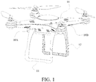
- FIG. 1 is a schematic structural diagram of an unmanned aerial vehicle according to Embodiment 1 of the present application.
- the unmanned aerial vehicle is a four-rotor unmanned aerial vehicle, and works in a MIMO mode.
- a MIMO antenna indicates multiple-input and multiple-output, and is usually used in IEEE 802.11n but is also applicable to other 802.11 technologies.
- MIMO technologies may be approximately divided into two types: transmit/receive diversity and spatial multiplexing.
- a MIMO antenna is sometimes referred to as spatial diversity because the MIMO antenna transmits and receives data by using multiple spatial paths, and MIMO technologies can improve a channel capacity. Therefore, in this embodiment, channels and capacities of signals received or sent by the unmanned aerial vehicle are large, which helps increase a flight height of the unmanned aerial vehicle and conveniently control the unmanned aerial vehicle.
- the unmanned aerial vehicle includes a body 10, a first foot stand 11, and a second foot stand 12.
- the first foot stand 11 is provided on a first side surface 10A of the body 10, and the second foot stand 12 is provided in a second side surface 10B of the body 10.
- FIG. 2 is a structural solid diagram of a first foot stand according to Embodiment 1 of the present application.
- the first foot stand 11 includes three connection racks.
- a first connection rack 111 is connected to the body 10
- one end of a third connection rack 113 is connected to the body 10
- the other end of the first connection rack 111 is connected to one end of a second connection rack 112
- the other end of the second connection rack 112 is connected to the other end of the third connection rack 113.
- Each connection rack is made of a highly hard material.
- connection racks are integrally connected, and the first foot stand is formed by die casting each connection rack once.
- integral connection the unmanned aerial vehicle can land on the ground more stably.
- connection racks may alternatively be separately connected, and are not limited to integral connection.
- the second foot stand includes a fourth connection rack, a fifth connection rack, and a sixth connection rack, and the fourth connection rack, the fifth connection rack, and the sixth connection rack are sequentially connected.
- the second foot stand and the first foot stand have the same overall structures, and details are not described herein.
- FIG. 3 is a schematic structural diagram in which a first dual-polarized antenna is provided inside a first foot stand according to Embodiment 1 of the present application
- FIG. 4 is a schematic structural diagram in which a second dual-polarized antenna is provided inside a second foot stand according to Embodiment 1 of the present application.
- the first dual-polarized antenna 31 is provided in the first foot stand 11, and in a direction perpendicular to the horizontal plane, the second dual-polarized antenna 32 is provided in the second foot stand 12.
- the dual-polarized antenna is respectively provided in the first foot stand 11 or the second foot stand 12. On one hand, this can fully use unoccupied space of the foot stand, and on the other hand, this can avoid a problem that because the dual-polarized antenna is provided in the body, aesthetic appeal of an external structure design of the body is reduced.
- the body 10 includes a signal receiving circuit and a signal sending circuit. Each dual-polarized antenna is respectively electrically connected to the signal receiving circuit and the signal sending circuit.
- the signal receiving circuit receives a signal fed by the antenna and processes the signal, and the signal sending circuit sends the signal by using the antenna.
- first limit columns 114 are provided inside the first foot stand 11 at intervals along an outline that defines the shape of the first foot stand 11. After the first dual-polarized antenna 31 is assembled in the first foot stand 11, the first limit column 114 limits the first dual-polarized antenna 31, to avoid a problem that in a flight process of the unmanned aerial vehicle, the first foot stand 11 shakes and consequently the first dual-polarized antenna 31 moves.
- FIG. 5 is a schematic structural diagram in which a first dual-polarized antenna is hidden behind a heat-shrinkable sleeve according to an embodiment of the present application
- FIG. 6 is a schematic structural diagram in which a first dual-polarized antenna is sleeved behind a heat-shrinkable sleeve according to an embodiment of the present application.
- the first dual-polarized antenna 31 includes a first copper pipe 311, a first radio frequency cable 312, and a first heat-shrinkable sleeve 313.
- the first radio frequency cable 312 includes a core cable 3121 and an external shield layer enclosing the core cable.
- the diameter of the core cable 3121 of the first radio frequency cable 312 is 1.37 mm.
- the core cable 3121 of the first radio frequency cable 312 passes through one end 311A of the first copper pipe 311, and a welding portion 50 is formed by the welding between the first soldering tin pad and the second soldering tin pad.
- the core cable 3121 of the first radio frequency cable 312 and the first copper pipe 311 are connected by the welding herein.
- an MMCX radio frequency connector is used as the first radio frequency connector 314.
- another radio frequency connector may be also used as the first radio frequency connector 314 herein.
- the first copper pipe 311 and the first radio frequency cable 312 are both provided in the first heat-shrinkable sleeve 313.
- the first heat-shrinkable sleeve 313 is used to protect the first dual-polarized antenna 31 and avoid that the unmanned aerial vehicle shakes in a flight process and consequently the first dual-polarized antenna 31 is damaged.
- second limit columns 121 are provided inside the second foot stand 12 at intervals along an outline that defines the shape of the second foot stand 12. After the second dual-polarized antenna 32 is assembled in the second foot stand 12, the second limit column 121 limits the second dual-polarized antenna 32, to avoid a problem that in a flight process of the unmanned aerial vehicle, the second foot stand 12 shakes and the second dual-polarized antenna 32 moves.
- FIG. 7 is a schematic structural diagram in which a second dual-polarized antenna is hidden behind a heat-shrinkable sleeve according to an embodiment of the present application
- FIG. 8 is a schematic structural diagram in which a second dual-polarized antenna is sleeved behind a heat-shrinkable sleeve according to an embodiment of the present application.
- the second dual-polarized antenna 32 includes a second copper pipe 321, a second radio frequency cable 322, and a second heat-shrinkable sleeve 323.
- the second radio frequency cable 322 includes a core cable 3221 and an external shield layer enclosing the core cable.
- the diameter of the core cable 3221 of the second radio frequency cable 322 is 1.37 mm.
- the core cable 3221 of the second radio frequency cable 322 passes through one end 321A of the second copper pipe 321, and a solder portion 60 is formed by welding between the third soldering tin pad and the fourth soldering tin pad.
- the core cable 3221 of the second radio frequency cable 322 and the second copper pipe 321 are connected by welding herein.
- an MMCX radio frequency connector is used as the second radio frequency connector 324.
- another radio frequency connector may be also used as the second radio frequency connector 324 herein.
- the second copper pipe 321 and the second radio frequency cable 322 are both provided in the second heat-shrinkable sleeve 323.
- the second heat-shrinkable sleeve 323 is used to protect the second dual-polarized antenna 32 and avoid that the unmanned aerial vehicle shakes in a flight process and consequently the second dual-polarized antenna 32 is damaged.
- coaxial antennas are used as the first dual-polarized antenna 31 and the second dual-polarized antenna 32, and are characterized by small sizes, light weights, simple structures, low costs, easy integration, and the like.
- a difference between this embodiment and Embodiment 1 is as follows: referring to FIG. 2 again, the first dual-polarized antenna 31 is horizontally provided in the second connection rack 112 of the first foot stand 11, and the second dual-polarized antenna 32 is vertically provided in the first connection rack 111 or the third connection rack 113 of the first foot stand 11.
- this structural design helps increase a horizontal flight distance and a vertical flight height of the unmanned aerial vehicle, and on the other hand, can save design space.
- a difference between this embodiment and Embodiment 1 or Embodiment 2 is as follows:
- the first dual-polarized antenna 31 is horizontally provided in a fifth connection rack of the second foot stand, and the second dual-polarized antenna 31 is vertically provided in a fourth connection rack or a sixth connection rack of the second foot stand.
- this structural design helps increase a horizontal flight distance and a vertical flight height of the unmanned aerial vehicle, and on the other hand, can save design space.
Landscapes
- Engineering & Computer Science (AREA)
- Aviation & Aerospace Engineering (AREA)
- Remote Sensing (AREA)
- Physics & Mathematics (AREA)
- Astronomy & Astrophysics (AREA)
- General Physics & Mathematics (AREA)
- Microelectronics & Electronic Packaging (AREA)
- Mechanical Engineering (AREA)
- Variable-Direction Aerials And Aerial Arrays (AREA)
- Details Of Aerials (AREA)
- Support Of Aerials (AREA)
Applications Claiming Priority (2)
| Application Number | Priority Date | Filing Date | Title |
|---|---|---|---|
| CN201620374088.8U CN205583125U (zh) | 2016-04-28 | 2016-04-28 | 一种无人机 |
| PCT/CN2016/093082 WO2017185554A1 (fr) | 2016-04-28 | 2016-08-03 | Véhicule aérien sans pilote |
Publications (3)
| Publication Number | Publication Date |
|---|---|
| EP3407421A1 true EP3407421A1 (fr) | 2018-11-28 |
| EP3407421A4 EP3407421A4 (fr) | 2019-02-20 |
| EP3407421B1 EP3407421B1 (fr) | 2020-10-28 |
Family
ID=56857732
Family Applications (1)
| Application Number | Title | Priority Date | Filing Date |
|---|---|---|---|
| EP16900063.5A Active EP3407421B1 (fr) | 2016-04-28 | 2016-08-03 | Véhicule aérien sans pilote |
Country Status (4)
| Country | Link |
|---|---|
| US (1) | US10707564B2 (fr) |
| EP (1) | EP3407421B1 (fr) |
| CN (1) | CN205583125U (fr) |
| WO (1) | WO2017185554A1 (fr) |
Families Citing this family (5)
| Publication number | Priority date | Publication date | Assignee | Title |
|---|---|---|---|---|
| CN206907920U (zh) * | 2016-12-14 | 2018-01-19 | 深圳市道通智能航空技术有限公司 | 一种双频段微带天线及应用该天线的无人机 |
| CN110277631B (zh) * | 2019-06-14 | 2024-11-01 | 深圳市道通智能航空技术股份有限公司 | 一种双频天线及飞行器 |
| CN210864418U (zh) * | 2019-12-19 | 2020-06-26 | 广州极飞科技有限公司 | 自驾控制装置及具有其的无人驾驶装置 |
| CN112249303A (zh) * | 2020-10-26 | 2021-01-22 | 东莞理工学院 | 一种扑翼微型飞行机器人的尾翼平衡器 |
| CN114586236B (zh) * | 2020-11-13 | 2025-03-18 | 深圳市大疆创新科技有限公司 | 无人机 |
Family Cites Families (9)
| Publication number | Priority date | Publication date | Assignee | Title |
|---|---|---|---|---|
| US5315309A (en) * | 1991-09-06 | 1994-05-24 | Mcdonnell Douglas Helicopter Company | Dual polarization antenna |
| US20090069957A1 (en) * | 2005-03-28 | 2009-03-12 | Yamaha Hatsudoki Kabushiki Kaisha | Unmanned helicopter |
| CN102331575B (zh) * | 2011-06-23 | 2013-01-30 | 中国电子科技集团公司第三十八研究所 | 一种单航过全极化干涉合成孔径雷达 |
| CN202221473U (zh) * | 2011-06-23 | 2012-05-16 | 中国电子科技集团公司第三十八研究所 | 一种单航过全极化干涉合成孔径雷达 |
| CN103165984B (zh) * | 2011-12-08 | 2016-10-05 | 京信通信系统(中国)有限公司 | 一种移动通信系统及其多波束天线装置 |
| CN202405421U (zh) * | 2011-12-08 | 2012-08-29 | 京信通信系统(中国)有限公司 | 一种移动通信系统及其多波束天线装置 |
| CN103490842B (zh) * | 2013-09-26 | 2016-09-28 | 深圳市大疆创新科技有限公司 | 数据传输系统及方法 |
| CN203921192U (zh) * | 2014-06-26 | 2014-11-05 | 深圳市大疆创新科技有限公司 | 一种飞行器及其信号线保护组件 |
| CN104134861A (zh) * | 2014-07-23 | 2014-11-05 | 深圳市视晶无线技术有限公司 | Mimo天线系统、近似全向的天线装置及其高增益微型天线 |
-
2016
- 2016-04-28 CN CN201620374088.8U patent/CN205583125U/zh not_active Expired - Lifetime
- 2016-08-03 EP EP16900063.5A patent/EP3407421B1/fr active Active
- 2016-08-03 WO PCT/CN2016/093082 patent/WO2017185554A1/fr not_active Ceased
-
2018
- 2018-09-26 US US16/142,619 patent/US10707564B2/en active Active
Also Published As
| Publication number | Publication date |
|---|---|
| WO2017185554A1 (fr) | 2017-11-02 |
| US20190036203A1 (en) | 2019-01-31 |
| CN205583125U (zh) | 2016-09-14 |
| EP3407421B1 (fr) | 2020-10-28 |
| EP3407421A4 (fr) | 2019-02-20 |
| US10707564B2 (en) | 2020-07-07 |
Similar Documents
| Publication | Publication Date | Title |
|---|---|---|
| US10707564B2 (en) | Unmanned aerial vehicle | |
| US12476351B2 (en) | Integrated antenna in an aerial vehicle | |
| EP3120411B1 (fr) | Antenne dirigée mécaniquement et à polarisation horizontale pour véhicule aérien, et systèmes et procédés associés | |
| CN106056875A (zh) | 一种多天线无人机系统的实现方法 | |
| US10468758B1 (en) | Zero weight airborne antenna with near perfect radiation efficiency utilizing conductive airframe elements and method | |
| US8493278B2 (en) | Antennas and methods to provide adaptable omnidirectional ground nulls | |
| US10644384B1 (en) | Zero weight airborne antenna with near perfect radiation efficiency utilizing conductive airframe elements and method | |
| US10476174B2 (en) | Patch antennas configuration for an unmanned aerial vehicle | |
| EP3939116B1 (fr) | Systèmes d'antenne air-sol directe pour aéronef | |
| CN111869121A (zh) | 包括天线元件面板的无人驾驶的飞行器 | |
| US20170317415A1 (en) | Compact steerable transmit antenna system | |
| CN205788719U (zh) | 一种多天线无人机系统 | |
| CN109075432A (zh) | 一种天线及无人机 | |
| US10187029B1 (en) | Phase shifter | |
| Dweik et al. | A planar antenna array with integrated feed network for UAV applications | |
| US8604985B1 (en) | Dual polarization antenna with high port isolation | |
| CN207517894U (zh) | 一种四阵元共口径多频段复合阵列天线 | |
| US11038273B1 (en) | Electronically scanning antenna assembly | |
| Ozman et al. | Gain enhancement of axial mode helical antenna for UAV applications | |
| CN106487927A (zh) | 一种多旋翼无人机的通信控制系统 | |
| CN207442848U (zh) | 可移动设备 | |
| US12620709B2 (en) | Full-duplex circular parasitic array assembly | |
| EP4496121A1 (fr) | Ensemble de réseau parasite circulaire en duplex intégral | |
| CN213584168U (zh) | 天线组件及无人机 | |
| KR20250057479A (ko) | 회전체를 활용한 안테나의 급전 데이터 전송방식 |
Legal Events
| Date | Code | Title | Description |
|---|---|---|---|
| STAA | Information on the status of an ep patent application or granted ep patent |
Free format text: STATUS: THE INTERNATIONAL PUBLICATION HAS BEEN MADE |
|
| PUAI | Public reference made under article 153(3) epc to a published international application that has entered the european phase |
Free format text: ORIGINAL CODE: 0009012 |
|
| STAA | Information on the status of an ep patent application or granted ep patent |
Free format text: STATUS: REQUEST FOR EXAMINATION WAS MADE |
|
| 17P | Request for examination filed |
Effective date: 20180823 |
|
| AK | Designated contracting states |
Kind code of ref document: A1 Designated state(s): AL AT BE BG CH CY CZ DE DK EE ES FI FR GB GR HR HU IE IS IT LI LT LU LV MC MK MT NL NO PL PT RO RS SE SI SK SM TR |
|
| AX | Request for extension of the european patent |
Extension state: BA ME |
|
| A4 | Supplementary search report drawn up and despatched |
Effective date: 20190123 |
|
| RIC1 | Information provided on ipc code assigned before grant |
Ipc: H01Q 21/24 20060101ALI20190117BHEP Ipc: H01Q 1/28 20060101AFI20190117BHEP |
|
| DAV | Request for validation of the european patent (deleted) | ||
| DAX | Request for extension of the european patent (deleted) | ||
| GRAP | Despatch of communication of intention to grant a patent |
Free format text: ORIGINAL CODE: EPIDOSNIGR1 |
|
| STAA | Information on the status of an ep patent application or granted ep patent |
Free format text: STATUS: GRANT OF PATENT IS INTENDED |
|
| INTG | Intention to grant announced |
Effective date: 20200515 |
|
| GRAS | Grant fee paid |
Free format text: ORIGINAL CODE: EPIDOSNIGR3 |
|
| GRAA | (expected) grant |
Free format text: ORIGINAL CODE: 0009210 |
|
| STAA | Information on the status of an ep patent application or granted ep patent |
Free format text: STATUS: THE PATENT HAS BEEN GRANTED |
|
| AK | Designated contracting states |
Kind code of ref document: B1 Designated state(s): AL AT BE BG CH CY CZ DE DK EE ES FI FR GB GR HR HU IE IS IT LI LT LU LV MC MK MT NL NO PL PT RO RS SE SI SK SM TR |
|
| REG | Reference to a national code |
Ref country code: GB Ref legal event code: FG4D |
|
| REG | Reference to a national code |
Ref country code: CH Ref legal event code: EP |
|
| REG | Reference to a national code |
Ref country code: AT Ref legal event code: REF Ref document number: 1329156 Country of ref document: AT Kind code of ref document: T Effective date: 20201115 |
|
| REG | Reference to a national code |
Ref country code: DE Ref legal event code: R096 Ref document number: 602016046933 Country of ref document: DE |
|
| REG | Reference to a national code |
Ref country code: IE Ref legal event code: FG4D |
|
| REG | Reference to a national code |
Ref country code: AT Ref legal event code: MK05 Ref document number: 1329156 Country of ref document: AT Kind code of ref document: T Effective date: 20201028 |
|
| REG | Reference to a national code |
Ref country code: NL Ref legal event code: MP Effective date: 20201028 |
|
| PG25 | Lapsed in a contracting state [announced via postgrant information from national office to epo] |
Ref country code: NO Free format text: LAPSE BECAUSE OF FAILURE TO SUBMIT A TRANSLATION OF THE DESCRIPTION OR TO PAY THE FEE WITHIN THE PRESCRIBED TIME-LIMIT Effective date: 20210128 Ref country code: PT Free format text: LAPSE BECAUSE OF FAILURE TO SUBMIT A TRANSLATION OF THE DESCRIPTION OR TO PAY THE FEE WITHIN THE PRESCRIBED TIME-LIMIT Effective date: 20210301 Ref country code: RS Free format text: LAPSE BECAUSE OF FAILURE TO SUBMIT A TRANSLATION OF THE DESCRIPTION OR TO PAY THE FEE WITHIN THE PRESCRIBED TIME-LIMIT Effective date: 20201028 Ref country code: FI Free format text: LAPSE BECAUSE OF FAILURE TO SUBMIT A TRANSLATION OF THE DESCRIPTION OR TO PAY THE FEE WITHIN THE PRESCRIBED TIME-LIMIT Effective date: 20201028 Ref country code: GR Free format text: LAPSE BECAUSE OF FAILURE TO SUBMIT A TRANSLATION OF THE DESCRIPTION OR TO PAY THE FEE WITHIN THE PRESCRIBED TIME-LIMIT Effective date: 20210129 |
|
| REG | Reference to a national code |
Ref country code: LT Ref legal event code: MG4D |
|
| PG25 | Lapsed in a contracting state [announced via postgrant information from national office to epo] |
Ref country code: AT Free format text: LAPSE BECAUSE OF FAILURE TO SUBMIT A TRANSLATION OF THE DESCRIPTION OR TO PAY THE FEE WITHIN THE PRESCRIBED TIME-LIMIT Effective date: 20201028 Ref country code: ES Free format text: LAPSE BECAUSE OF FAILURE TO SUBMIT A TRANSLATION OF THE DESCRIPTION OR TO PAY THE FEE WITHIN THE PRESCRIBED TIME-LIMIT Effective date: 20201028 Ref country code: IS Free format text: LAPSE BECAUSE OF FAILURE TO SUBMIT A TRANSLATION OF THE DESCRIPTION OR TO PAY THE FEE WITHIN THE PRESCRIBED TIME-LIMIT Effective date: 20210228 Ref country code: LV Free format text: LAPSE BECAUSE OF FAILURE TO SUBMIT A TRANSLATION OF THE DESCRIPTION OR TO PAY THE FEE WITHIN THE PRESCRIBED TIME-LIMIT Effective date: 20201028 Ref country code: PL Free format text: LAPSE BECAUSE OF FAILURE TO SUBMIT A TRANSLATION OF THE DESCRIPTION OR TO PAY THE FEE WITHIN THE PRESCRIBED TIME-LIMIT Effective date: 20201028 Ref country code: BG Free format text: LAPSE BECAUSE OF FAILURE TO SUBMIT A TRANSLATION OF THE DESCRIPTION OR TO PAY THE FEE WITHIN THE PRESCRIBED TIME-LIMIT Effective date: 20210128 Ref country code: SE Free format text: LAPSE BECAUSE OF FAILURE TO SUBMIT A TRANSLATION OF THE DESCRIPTION OR TO PAY THE FEE WITHIN THE PRESCRIBED TIME-LIMIT Effective date: 20201028 |
|
| PG25 | Lapsed in a contracting state [announced via postgrant information from national office to epo] |
Ref country code: HR Free format text: LAPSE BECAUSE OF FAILURE TO SUBMIT A TRANSLATION OF THE DESCRIPTION OR TO PAY THE FEE WITHIN THE PRESCRIBED TIME-LIMIT Effective date: 20201028 Ref country code: NL Free format text: LAPSE BECAUSE OF FAILURE TO SUBMIT A TRANSLATION OF THE DESCRIPTION OR TO PAY THE FEE WITHIN THE PRESCRIBED TIME-LIMIT Effective date: 20201028 |
|
| REG | Reference to a national code |
Ref country code: DE Ref legal event code: R097 Ref document number: 602016046933 Country of ref document: DE |
|
| PG25 | Lapsed in a contracting state [announced via postgrant information from national office to epo] |
Ref country code: SK Free format text: LAPSE BECAUSE OF FAILURE TO SUBMIT A TRANSLATION OF THE DESCRIPTION OR TO PAY THE FEE WITHIN THE PRESCRIBED TIME-LIMIT Effective date: 20201028 Ref country code: RO Free format text: LAPSE BECAUSE OF FAILURE TO SUBMIT A TRANSLATION OF THE DESCRIPTION OR TO PAY THE FEE WITHIN THE PRESCRIBED TIME-LIMIT Effective date: 20201028 Ref country code: CZ Free format text: LAPSE BECAUSE OF FAILURE TO SUBMIT A TRANSLATION OF THE DESCRIPTION OR TO PAY THE FEE WITHIN THE PRESCRIBED TIME-LIMIT Effective date: 20201028 Ref country code: EE Free format text: LAPSE BECAUSE OF FAILURE TO SUBMIT A TRANSLATION OF THE DESCRIPTION OR TO PAY THE FEE WITHIN THE PRESCRIBED TIME-LIMIT Effective date: 20201028 Ref country code: LT Free format text: LAPSE BECAUSE OF FAILURE TO SUBMIT A TRANSLATION OF THE DESCRIPTION OR TO PAY THE FEE WITHIN THE PRESCRIBED TIME-LIMIT Effective date: 20201028 Ref country code: SM Free format text: LAPSE BECAUSE OF FAILURE TO SUBMIT A TRANSLATION OF THE DESCRIPTION OR TO PAY THE FEE WITHIN THE PRESCRIBED TIME-LIMIT Effective date: 20201028 |
|
| PG25 | Lapsed in a contracting state [announced via postgrant information from national office to epo] |
Ref country code: DK Free format text: LAPSE BECAUSE OF FAILURE TO SUBMIT A TRANSLATION OF THE DESCRIPTION OR TO PAY THE FEE WITHIN THE PRESCRIBED TIME-LIMIT Effective date: 20201028 |
|
| PLBE | No opposition filed within time limit |
Free format text: ORIGINAL CODE: 0009261 |
|
| STAA | Information on the status of an ep patent application or granted ep patent |
Free format text: STATUS: NO OPPOSITION FILED WITHIN TIME LIMIT |
|
| 26N | No opposition filed |
Effective date: 20210729 |
|
| PG25 | Lapsed in a contracting state [announced via postgrant information from national office to epo] |
Ref country code: AL Free format text: LAPSE BECAUSE OF FAILURE TO SUBMIT A TRANSLATION OF THE DESCRIPTION OR TO PAY THE FEE WITHIN THE PRESCRIBED TIME-LIMIT Effective date: 20201028 Ref country code: IT Free format text: LAPSE BECAUSE OF FAILURE TO SUBMIT A TRANSLATION OF THE DESCRIPTION OR TO PAY THE FEE WITHIN THE PRESCRIBED TIME-LIMIT Effective date: 20201028 |
|
| PG25 | Lapsed in a contracting state [announced via postgrant information from national office to epo] |
Ref country code: SI Free format text: LAPSE BECAUSE OF FAILURE TO SUBMIT A TRANSLATION OF THE DESCRIPTION OR TO PAY THE FEE WITHIN THE PRESCRIBED TIME-LIMIT Effective date: 20201028 |
|
| REG | Reference to a national code |
Ref country code: CH Ref legal event code: PL |
|
| PG25 | Lapsed in a contracting state [announced via postgrant information from national office to epo] |
Ref country code: MC Free format text: LAPSE BECAUSE OF FAILURE TO SUBMIT A TRANSLATION OF THE DESCRIPTION OR TO PAY THE FEE WITHIN THE PRESCRIBED TIME-LIMIT Effective date: 20201028 |
|
| REG | Reference to a national code |
Ref country code: BE Ref legal event code: MM Effective date: 20210831 |
|
| PG25 | Lapsed in a contracting state [announced via postgrant information from national office to epo] |
Ref country code: LI Free format text: LAPSE BECAUSE OF NON-PAYMENT OF DUE FEES Effective date: 20210831 Ref country code: CH Free format text: LAPSE BECAUSE OF NON-PAYMENT OF DUE FEES Effective date: 20210831 |
|
| PG25 | Lapsed in a contracting state [announced via postgrant information from national office to epo] |
Ref country code: IS Free format text: LAPSE BECAUSE OF FAILURE TO SUBMIT A TRANSLATION OF THE DESCRIPTION OR TO PAY THE FEE WITHIN THE PRESCRIBED TIME-LIMIT Effective date: 20210228 Ref country code: LU Free format text: LAPSE BECAUSE OF NON-PAYMENT OF DUE FEES Effective date: 20210803 |
|
| PG25 | Lapsed in a contracting state [announced via postgrant information from national office to epo] |
Ref country code: IE Free format text: LAPSE BECAUSE OF NON-PAYMENT OF DUE FEES Effective date: 20210803 Ref country code: BE Free format text: LAPSE BECAUSE OF NON-PAYMENT OF DUE FEES Effective date: 20210831 |
|
| PG25 | Lapsed in a contracting state [announced via postgrant information from national office to epo] |
Ref country code: CY Free format text: LAPSE BECAUSE OF FAILURE TO SUBMIT A TRANSLATION OF THE DESCRIPTION OR TO PAY THE FEE WITHIN THE PRESCRIBED TIME-LIMIT Effective date: 20201028 |
|
| PG25 | Lapsed in a contracting state [announced via postgrant information from national office to epo] |
Ref country code: HU Free format text: LAPSE BECAUSE OF FAILURE TO SUBMIT A TRANSLATION OF THE DESCRIPTION OR TO PAY THE FEE WITHIN THE PRESCRIBED TIME-LIMIT; INVALID AB INITIO Effective date: 20160803 |
|
| PG25 | Lapsed in a contracting state [announced via postgrant information from national office to epo] |
Ref country code: MK Free format text: LAPSE BECAUSE OF FAILURE TO SUBMIT A TRANSLATION OF THE DESCRIPTION OR TO PAY THE FEE WITHIN THE PRESCRIBED TIME-LIMIT Effective date: 20201028 |
|
| PG25 | Lapsed in a contracting state [announced via postgrant information from national office to epo] |
Ref country code: MT Free format text: LAPSE BECAUSE OF FAILURE TO SUBMIT A TRANSLATION OF THE DESCRIPTION OR TO PAY THE FEE WITHIN THE PRESCRIBED TIME-LIMIT Effective date: 20201028 |
|
| PGFP | Annual fee paid to national office [announced via postgrant information from national office to epo] |
Ref country code: GB Payment date: 20240826 Year of fee payment: 9 |
|
| PGFP | Annual fee paid to national office [announced via postgrant information from national office to epo] |
Ref country code: DE Payment date: 20250820 Year of fee payment: 10 |
|
| PGFP | Annual fee paid to national office [announced via postgrant information from national office to epo] |
Ref country code: FR Payment date: 20250828 Year of fee payment: 10 |
|
| PG25 | Lapsed in a contracting state [announced via postgrant information from national office to epo] |
Ref country code: TR Free format text: LAPSE BECAUSE OF FAILURE TO SUBMIT A TRANSLATION OF THE DESCRIPTION OR TO PAY THE FEE WITHIN THE PRESCRIBED TIME-LIMIT Effective date: 20201028 |