EP3407428B1 - Structure de ressort en feuille métallique de borne de connexion électrique - Google Patents
Structure de ressort en feuille métallique de borne de connexion électrique Download PDFInfo
- Publication number
- EP3407428B1 EP3407428B1 EP18173947.5A EP18173947A EP3407428B1 EP 3407428 B1 EP3407428 B1 EP 3407428B1 EP 18173947 A EP18173947 A EP 18173947A EP 3407428 B1 EP3407428 B1 EP 3407428B1
- Authority
- EP
- European Patent Office
- Prior art keywords
- section
- electrical connection
- locating
- leaf spring
- metal leaf
- Prior art date
- Legal status (The legal status is an assumption and is not a legal conclusion. Google has not performed a legal analysis and makes no representation as to the accuracy of the status listed.)
- Active
Links
Images


Classifications
-
- H—ELECTRICITY
- H01—ELECTRIC ELEMENTS
- H01R—ELECTRICALLY-CONDUCTIVE CONNECTIONS; STRUCTURAL ASSOCIATIONS OF A PLURALITY OF MUTUALLY-INSULATED ELECTRICAL CONNECTING ELEMENTS; COUPLING DEVICES; CURRENT COLLECTORS
- H01R12/00—Structural associations of a plurality of mutually-insulated electrical connecting elements, specially adapted for printed circuits, e.g. printed circuit boards [PCB], flat or ribbon cables, or like generally planar structures, e.g. terminal strips, terminal blocks; Coupling devices specially adapted for printed circuits, flat or ribbon cables, or like generally planar structures; Terminals specially adapted for contact with, or insertion into, printed circuits, flat or ribbon cables, or like generally planar structures
- H01R12/50—Fixed connections
- H01R12/51—Fixed connections for rigid printed circuits or like structures
- H01R12/515—Terminal blocks providing connections to wires or cables
-
- H—ELECTRICITY
- H01—ELECTRIC ELEMENTS
- H01R—ELECTRICALLY-CONDUCTIVE CONNECTIONS; STRUCTURAL ASSOCIATIONS OF A PLURALITY OF MUTUALLY-INSULATED ELECTRICAL CONNECTING ELEMENTS; COUPLING DEVICES; CURRENT COLLECTORS
- H01R4/00—Electrically-conductive connections between two or more conductive members in direct contact, i.e. touching one another; Means for effecting or maintaining such contact; Electrically-conductive connections having two or more spaced connecting locations for conductors and using contact members penetrating insulation
- H01R4/28—Clamped connections, spring connections
- H01R4/48—Clamped connections, spring connections utilising a spring, clip, or other resilient member
- H01R4/4809—Clamped connections, spring connections utilising a spring, clip, or other resilient member using a leaf spring to bias the conductor toward the busbar
- H01R4/48185—Clamped connections, spring connections utilising a spring, clip, or other resilient member using a leaf spring to bias the conductor toward the busbar adapted for axial insertion of a wire end
- H01R4/4819—Clamped connections, spring connections utilising a spring, clip, or other resilient member using a leaf spring to bias the conductor toward the busbar adapted for axial insertion of a wire end the spring shape allowing insertion of the conductor end when the spring is unbiased
- H01R4/4821—Single-blade spring
-
- H—ELECTRICITY
- H01—ELECTRIC ELEMENTS
- H01R—ELECTRICALLY-CONDUCTIVE CONNECTIONS; STRUCTURAL ASSOCIATIONS OF A PLURALITY OF MUTUALLY-INSULATED ELECTRICAL CONNECTING ELEMENTS; COUPLING DEVICES; CURRENT COLLECTORS
- H01R4/00—Electrically-conductive connections between two or more conductive members in direct contact, i.e. touching one another; Means for effecting or maintaining such contact; Electrically-conductive connections having two or more spaced connecting locations for conductors and using contact members penetrating insulation
- H01R4/28—Clamped connections, spring connections
- H01R4/48—Clamped connections, spring connections utilising a spring, clip, or other resilient member
- H01R4/4809—Clamped connections, spring connections utilising a spring, clip, or other resilient member using a leaf spring to bias the conductor toward the busbar
- H01R4/4846—Busbar details
Definitions
- the present invention relates to a metal leaf spring structure of electrical connection terminal.
- a conventional terminal device or wire pressing terminal has an insulation case (generally made of plastic material) and an electrical connector or metal member (or metal leaf spring).
- the metal leaf spring is enclosed in the insulation case to press and electrically connect with or release a conductive wire plugged into the terminal device.
- Such electrical connection terminal devices include two types.
- the first type of electrical connection terminal device is inserted on a circuit board such as printed circuit board (PCB).
- the second type of electrical connection terminal device is latched with a grounding rail (or conductive rail) in a row to set up a common grounding device of an electrical apparatus or mechanical equipment.
- the aforesaid electrical connection terminal is inserted on a circuit board such as printed circuit board (PCB) or a grounding rail and includes an insulation case having a perforation or a wire plug-in hole for the conductive wire to plug into the interior of the case.
- the case defines a chamber in which the electrical connector (or the metal leaf spring) is mounted.
- the metal leaf spring serves to contact or electrically connect with the conductive wire plugged into the case.
- the electrical connector has an elastic free end. After the conductive wire is plugged into the case, the free end of the electrical connector will bite the conductive wire to prevent the conductive wire from easily detaching from the electrical connector out of contact with the electrical connector. Unless an operator uses a tool to extend into the case and push/press the free end, the conductive wire cannot be released from the contact of the electrical connector.
- the metal leaf spring of the conventional electrical connection terminal device has some shortcomings in structural design and application. For example, when plugging the conductive wire into the terminal device, due to human operation factor, it often takes place that the conductive wire cannot enter the terminal device by a precise angle to push/press the free end of the metal leaf spring. In this case, the elastic free end of the metal leaf spring can hardly securely press and restrict the conductive wire or the metal leaf spring will be over-bent. Especially, after a long period of high-frequency assembling operation of the conductive wire, elastic fatigue is apt to happen to the structure of the metal leaf spring.
- the conventional clamping spring (or metal leaf spring) is assembled with a reception member (or frame body).
- a protrusion section is formed on one side of the reception member in the moving path of the clamping leg (or free end) of the clamping spring to prevent the clamping leg from being over-biased.
- the structure of the additional protrusion section of the reception member (or frame body) in cooperation with the clamping spring is relatively complicated.
- the conductive wire when the conductive wire is plugged into the electrical connection terminal by an imprecise angle, the conductive wire also will push/press the clamping leg of the clamping spring to deflect the clamping leg and make the clamping leg pass over the protrusion section. This deteriorates the effect that the protrusion section prevents the clamping leg from being over-biased. This is not what we expect.
- V-shaped metal leaf spring having a clamping arm and mounted in the terminal case for securely holding the conductive wire.
- the metal leaf spring has a support arm for preventing the metal leaf spring from being over-bent.
- JP 2-117671 discloses an assembling structure of a metal leaf spring and an electrical connection assembly, including a plate section 14. One end of the plate section 14 is arched and bent to form a bending section and a clamping arm SB2 connected with the bending section. The other end of the plate section 14 is bent to extend and form an assistant plate SB1 (or locating section).
- the assistant plate SB1 is elastically deformable to enhance the clamping force of the clamping arm SB2.
- US 2003/0017754 A1 discloses an ⁇ -shaped metal leaf spring structure including a fixing leg. One end of the fixing leg is bent to form a bending section and a base section connected with the bending section. The other end of the fixing leg is formed with an arched protrusion section and assistant section connected with the protrusion section. The assistant section is formed with an arched structure and assistant section along the bending section and the base section (so as to enhance the clamping force of the metal leaf spring and prevent the metal leaf spring from being over-bent).
- US 2011/0312228 A1 discloses an assembling structure of a metal leaf spring and an electrical connection member, including a V-shaped metal leaf spring having a clamping arm and mounted in the electrical connection member to securely clamp the conductive wire.
- US 8579651 B2 discloses an assembling structure of a metal leaf spring and a terminal (or electrical connector). It includes a V-shaped metal leaf spring having a clamping arm in cooperation with an actuating button mounted in the insulating material housing to securely clamp the conductive wire. The tail end of the contact leg is directed to the clamping leg. Such structural form is different from the structural feature of the present invention. US 8579651 B2 cannot solve or improve the problem that the metal leaf spring is over-bent to affect the life time.
- EP 3116065 A1 discloses a push-in clamp retainer for an electric connector. Two ends of the second bend region of the spring member are respectively connected with the first bend region and the second end of the spring member. The first end of the spring member is securely inserted in the receiving member and the slit of the push-in clamp retainer, whereby the second end of the spring member can cooperate with the push-in clamp retainer to press the conductive wire.
- the metal leaf spring structure includes a main body.
- the main body has a base section defined with a first end and a second end.
- the first end is connected with a first section and a locating section.
- the second end is connected with a bight section and a reciprocally movable second section.
- the locating section is positioned in the reciprocally moving path of the second section to set up a moving end point of the second section.
- a bent section is formed between the first end of the base section and the first section.
- the bent section contains an angle.
- the first section is bent toward the second end of the base section and obliquely extends to connect with the locating section, whereby a subsidiary bent section is formed between the first section and the locating section.
- the subsidiary bent section contains an angle.
- the bight section between the second end and the second section of the base section contains an angle, whereby the second section obliquely extends in a direction to the first end of the base section.
- a protrusion section is formed on the locating section.
- the (insulation) case or the electrical connection member is formed with a recess.
- the protrusion section can be fixed in the recess to help in fixing the locating section.
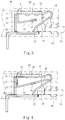
- the metal leaf spring structure of electrical connection terminal of the present invention includes a main body 100.
- the main body 100 is selectively made of elastic metal sheet or the like material by means of pressing in the form of a plate body.
- the main body 100 is mounted on a case 90 made of insulation material.
- the main body 100 is assembled with an electrical connection member 80 and the main body 100 and the electrical connection member 80 are together assembled and mounted on the case 90.
- the main body 100 includes a base section 30 defined with a first end 31 and a second end 32.
- the first end 31 is connected with a first section 10 and a locating section 40.
- the second end 32 is connected with a bight section 50 and a reciprocally movable second section 20.
- the locating section 40 is positioned in a reciprocally moving path of the second section 20 to set up a moving end point or moving range of the second section 20.
- a bent section 11 is formed between the first end 31 of the base section and the first section 10.
- the bent section 11 contains an angle, which is an acute angle, a right angle or an obtuse angle.
- the first section 31 is bent toward the second end 32 of the base section and extends to connect with the locating section 40, whereby a subsidiary bent section 12 is formed between the first section 10 and the locating section 40.
- the subsidiary bent section 12 contains an angle, which is an acute angle, a right angle or an obtuse angle.
- the locating section 40 obliquely extends in a direction to the upper side of the drawing, whereby the angle contained between the first section 10 and the locating section 40 (or the subsidiary bent section 12) is an acute angle.
- the second section 20 obliquely extends in a direction to the lower side of the drawing, whereby the angle contained between the second section 20 and the base section 30 is an acute angle.
- the bight section 50 between the second end 32 and the second section 20 of the base section contains an angle, whereby the second section 20 extends in a direction to the first end 31 of the base section. At this time, it is defined that the second section 20 is positioned in an initial position.
- the subsidiary bent section 12 enables the locating section 40 to provide an elastic action force for helping the second section 20 to move backward toward the initial position. Accordingly, the second section 20 is prevented from being over-biased.
- a protrusion section 41 is formed on an edge or a lateral side of the locating section 40.
- the (insulation) case 90 or the electrical connection member 80 is formed with a recess.
- the protrusion section 41 can be fixed in the recess to help in fixing the locating section 40.
- the electrical connection member 80 is formed as a frame body for receiving the main body 100.
- the electrical connection member 80 is formed with a recess 81 in which the protrusion section 41 of the locating section 40 is securely assembled.
- the lateral side of the base section 30 is formed with finger sections 33 and the electrical connection member 80 is formed with mouth sections 83.
- the finger sections 33 can be inserted in the mouth sections 83 to securely assemble the main body 100 with the electrical connection member 80 with the second section 20 freely reciprocally movable.
- the case 90 has a wire plug-in hole 92.
- the conductive wire 70 can be plugged through the wire plug-in hole 92 into the case 90 to be pressed and restricted by the main body 100 and electrically connected with the electrical connection member 80.
- the conductive wire 70 pushes the second section 20 to move in a direction to the locating section 40. Also, in cooperation with the structure of the bight section 50, the second section 20 or the tail end 22 of the second section 20 swings toward the lower side of the drawing to securely press and restrict the conductive wire 70 entering the case 90 or the electrical connection member 80.
- the locating section 40 of the main body 100 serves as a moving end point structure of the second section 20. This ensures that when the second section 20 is pushed/pressed and biased by the conductive wire 70, the second section 20 is prevented from being over-biased as the clamping leg of the conventional terminal that passes over the stop point (or the protrusion section).
- the locating section 40 has the form of an (entirely) plane structure, whereby the second section 20 can snugly attach to the locating section 40 without deflecting.
- Fig. 4 shows a modified embodiment of the main body 100 of the present invention.
- the locating section 40 of the main body has a tail section 42 extending to a position close to the bight section 50. Therefore, when the conductive wire 70 pushes the second section 20 to move toward the locating section 40, in case the second section 20 reaches or contacts the tail section 42, the tail section 42 can prevent the second section 20 from being over-biased. Also, with the position where the protrusion section 41 is assembled with the recess 81 serving as a fulcrum, the tail section 42 will provide an elastic action force to help the bight section 50 to increase the pressing force of the second section 20 against the conductive wire 70.
- Fig. 4 also shows a preferred embodiment in which the first section 10 is attached to the sidewall 82 of the electrical connection member 80, whereby the electrical connection member 80 provides a support effect for the main body 100 so that the main body 100 and the electrical connection member 80 can be more securely assembled with each other.
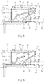
- Fig. 5 shows a modified embodiment of the main body 100 of the present invention.
- a connection section 13 is disposed between the subsidiary bent section 12 and the locating section 40.
- connection section 13 obliquely extends in a direction to the base section 30 and the second end 32 to form a reverse bent section 14 connected with the locating section 40.
- the angle contained between the first section 10 and the connection section 13 (or the subsidiary bent section 12) is an acute angle smaller than the obtuse angle contained between the connection section 13 and the locating section 40 (or the reverse bent section 14).
- Fig. 6 shows the structure of the subsidiary bent section 12 between the first section 10 and the locating section 40.
- the subsidiary bent section 12 is formed with an arched structure as the connection section 13.
- the connection section 13 obliquely extends in a direction to the base section 30 and the second end 32 to form the reverse bent section 14 connected with the locating section 40.
- first section 10 the structural form of the first section 10, the subsidiary bent section 12 and the connection section 13 as shown in Figs. 5 and 6 increases the length of the first section 10.
- attachment length or area of the first section 10 to the sidewall 82 of the electrical connection member is increased so that the electrical connection member 80 can provide greater support effect for the main body 100 and the main body 100 and the electrical connection member 80 can be more securely assembled with each other.
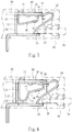
- Fig. 7 shows a modified embodiment of the main body 100 of the present invention.
- the tail section 42 of the locating section 40 of the main body is bent toward the base section 30 into contact with the base section 30 to form a locating portion structure and set up an auxiliary locating support point to enhance the effect that the locating section 40 prevents the second section 20 from being over-biased and the securing system of the assembly of the protrusion section 41 and the recess 81.
- Fig. 8 shows the structures of the subsidiary bent section 12 between the first section 10 and the locating section 40 of the main body and the head section 41 and the locating portion formed on the locating section 40.
- the subsidiary bent section 12 is formed with an arched structure as the connection section 13.
- the connection section 13 obliquely extends in a direction to the base section 30 and the second end 32 to form the reverse bent section 14 connected with the locating section 40.
- Fig. 9 is a view of a modified embodiment of the main body 100, showing the structures of the subsidiary bent section 12 between the first section 10 and the locating section 40 and the locating section 40 extending to the bight section 50.
- the subsidiary bent section 12 is formed with an arched structure as the connection section 13.
- the connection section 13 obliquely extends in a direction to the base section 30 and the second end 32 to form the reverse bent section 14 connected with the locating section 40.
- Fig. 9 also shows that the tail section 42 of the locating section 40 extends to a position close to the bight section 50 to form a hook structure along the curvature of the bight section 50. Therefore, when the conductive wire 70 pushes the second section 20 to move toward the locating sect ion 40, in case the second sect ion 20 reaches or contacts the tail section 42, the hook structure of the tail section 42 will prevent the second section 20 from being over-biased. Also, the tail section 42 will provide an elastic action force to push/press the second section 20 to increase the pressing force of the second section 20 against the conductive wire 70.
- Fig. 10 shows a preferred embodiment of the main body 100 of the present invention.
- the length of the first section 10 is as minimized as possible.
- the first section 10 is bent toward the second end 32 of the base section and extends to form the locating section 40.
- the locating section 40 is parallel to the base section 30.
- the tail section 42 of the locating section 40 extends to a position close to the bight section 50.
- the metal leaf spring structure of electrical connection terminal of the present invention is different from the conventional electrical connection terminal in space form and is advantageous over the conventional electrical connection terminal.
Landscapes
- Coupling Device And Connection With Printed Circuit (AREA)
- Details Of Connecting Devices For Male And Female Coupling (AREA)
Claims (9)
- Structure de ressort à lame métallique de borne de connexion électrique, comprenant un corps principal (100), le corps principal (100) ayant une section de base (30) définie avec une première extrémité (31) et une seconde extrémité (32), la première extrémité (31) étant reliée à une première section (10) et une section de positionnement (40), la seconde extrémité (32) étant reliée à une section recourbée (50) et une seconde section mobile en va-et-vient (20), une section pliée (11) étant formée entre la première extrémité (31) de la section de base (30) et la première section (10), la section pliée (11) contenant un angle, la première section (10) étant pliée vers la seconde extrémité (32) de la section de base (30) et s'étendant pour se relier à la section de positionnement (40), ce par quoi une section pliée secondaire (12) est formée entre la première section (10) et la section de positionnement (40), la section pliée secondaire (12) contenant un angle, la section recourbée (50) entre la seconde extrémité (32) et la seconde section (20) de la section de base (30) contenant un angle, ce par quoi la seconde section (20) s'étend de manière oblique dans une direction vers la première extrémité (31) de la section de base (30), la section de positionnement (40) étant positionnée dans un trajet de déplacement en va-et-vient de la seconde section (20) pour définir un point de fin de déplacement de la seconde section (20),
caractérisée par le fait qu'une section en saillie (41) est formée sur un côté latéral de la section de positionnement (40), la section en saillie étant apte à être fixée dans un évidement (81) formé sur un boîtier (90) ou un élément de connexion électrique (80). - Structure de ressort à lame métallique de borne de connexion électrique selon la revendication 1, la structure de ressort à lame métallique comprenant l'élément de connexion électrique (80), dans laquelle un côté latéral de la section de base (30) comporte des sections doigts (33) et l'élément de connexion électrique (80) comporte des sections embouts (83), les sections doigts (33) étant introduites dans les sections embouts (83) pour assembler solidement le corps principal (100) avec l'élément de connexion électrique (80), la première section (10) étant fixée à une paroi latérale (82) de l'élément de connexion électrique (80).
- Structure de ressort à lame métallique de borne de connexion électrique selon la revendication 1 ou 2, dans laquelle l'angle contenu par la section pliée (11) est choisi parmi un groupe constitué d'un angle aigu, d'un angle droit et d'un angle obtus, et l'angle contenu par la section pliée secondaire (12) est choisi parmi un groupe constitué d'un angle aigu, d'un angle droit et d'un angle obtus.
- Structure de ressort à lame métallique de borne de connexion électrique selon l'une quelconque des revendications 1 à 3, dans laquelle la section de positionnement (40) du corps principal (100) a la forme d'une structure plane, la section de positionnement (40) ayant une section arrière (42), la section arrière (42) s'étendant jusqu'à une position de la section recourbée (50) pour fournir une force d'action élastique.
- Structure de ressort à lame métallique de borne de connexion électrique selon l'une quelconque des revendications 1 à 4, dans laquelle une section de connexion (13) est disposée entre la section pliée secondaire (12) et la section de positionnement (40) du corps principal (100), la section de connexion (13) s'étendant de manière oblique dans une direction vers la section de base (30) et la seconde extrémité (32) pour former une section pliée inverse (14) reliée à la section de positionnement (40), un angle contenu entre la première section (10) et la section de connexion (13) étant un angle aigu plus petit qu'un angle obtus contenu par la section pliée inverse (14) entre la section de connexion (13) et la section de positionnement (40).
- Structure de ressort à lame métallique de borne de connexion électrique selon l'une quelconque des revendications 1 à 5, dans laquelle la section pliée secondaire (12) est formée avec une structure en arc.
- Structure de ressort à lame métallique de borne de connexion électrique selon l'une quelconque des revendications 1 à 6, dans laquelle la section de positionnement (40) du corps principal (100) a une section arrière (42), la section arrière (42) étant pliée vers la section de base (30) jusqu'à être en contact avec la section de base (30).
- Structure de ressort à lame métallique de borne de connexion électrique selon l'une quelconque des revendications 1 à 6, dans laquelle la section de positionnement (40) du corps principal (100) a une section arrière (42), la section arrière (42) s'étendant jusqu'à une position de la section recourbée (50) pour former une structure de crochet le long de la courbure de la section recourbée (50), ce par quoi la section arrière (42) peut fournir une force d'action élastique.
- Structure de ressort à lame métallique de borne de connexion électrique selon l'une quelconque des revendications 1 à 6, dans laquelle, par l'intermédiaire de la section pliée secondaire (12), la première section (10) du corps principal (100) est pliée vers la seconde extrémité (32) de la section de base (30) et s'étend pour former la section de positionnement (40), la section de positionnement (40) étant parallèle à la section de base (30), la section de positionnement (40) ayant une section arrière (42) s'étendant jusqu'à une position de la section recourbée (50).
Applications Claiming Priority (1)
| Application Number | Priority Date | Filing Date | Title |
|---|---|---|---|
| TW106207567U TWM550924U (zh) | 2017-05-26 | 2017-05-26 | 用於電聯接端子之金屬彈片結構 |
Publications (2)
| Publication Number | Publication Date |
|---|---|
| EP3407428A1 EP3407428A1 (fr) | 2018-11-28 |
| EP3407428B1 true EP3407428B1 (fr) | 2021-10-06 |
Family
ID=61013715
Family Applications (1)
| Application Number | Title | Priority Date | Filing Date |
|---|---|---|---|
| EP18173947.5A Active EP3407428B1 (fr) | 2017-05-26 | 2018-05-24 | Structure de ressort en feuille métallique de borne de connexion électrique |
Country Status (3)
| Country | Link |
|---|---|
| US (1) | US10622730B2 (fr) |
| EP (1) | EP3407428B1 (fr) |
| TW (1) | TWM550924U (fr) |
Families Citing this family (6)
| Publication number | Priority date | Publication date | Assignee | Title |
|---|---|---|---|---|
| TWI619317B (zh) * | 2016-06-20 | 2018-03-21 | Improved structure of the connector head limiter of the wire connection terminal | |
| TWM553505U (zh) * | 2017-05-26 | 2017-12-21 | Switchlab Inc | 用於電聯接端子之金屬彈片改良結構 |
| TWI666836B (zh) * | 2018-03-16 | 2019-07-21 | 進聯工業股份有限公司 | 電性接線裝置之導電組件結構 |
| DE102018117508B4 (de) * | 2018-07-19 | 2024-01-18 | Wago Verwaltungsgesellschaft Mbh | Leiteranschlussklemme |
| CN115693138A (zh) * | 2021-07-28 | 2023-02-03 | 华为技术有限公司 | 穿戴式电子设备机芯、外壳及穿戴式电子设备 |
| BE1029961B1 (de) * | 2021-11-25 | 2023-06-26 | Phoenix Contact Gmbh & Co | Anschlussanordnung und Anschlussklemme |
Citations (2)
| Publication number | Priority date | Publication date | Assignee | Title |
|---|---|---|---|---|
| US8579651B2 (en) * | 2009-07-18 | 2013-11-12 | Weidmueller Interface Gmbh & Co. Kg | Connection device for conductors |
| EP3116065A1 (fr) * | 2015-07-07 | 2017-01-11 | TE Connectivity Germany GmbH | Dispositif de retenue à emmanchement, ensemble de serrage et élément de connecteur électrique |
Family Cites Families (14)
| Publication number | Priority date | Publication date | Assignee | Title |
|---|---|---|---|---|
| US4637677A (en) * | 1984-12-18 | 1987-01-20 | Amp Incorporated | Electrical connector |
| JPH0548371Y2 (fr) * | 1989-03-06 | 1993-12-24 | ||
| US6062918A (en) * | 1996-07-01 | 2000-05-16 | The Whitaker Corporation | Electrical receptacle contact assembly |
| FR2815177B1 (fr) * | 2000-10-10 | 2005-02-11 | Entrelec Sa | Ressort de connexion et bloc de raccordement mettant en oeuvre un tel ressort |
| DE10135597B4 (de) * | 2001-07-20 | 2008-01-10 | Wieland Electric Gmbh | Klemmfeder |
| DE10315668B4 (de) * | 2002-08-28 | 2007-06-06 | Conrad Stanztechnik Gmbh | Anschlußklemme |
| US7249963B2 (en) * | 2005-07-11 | 2007-07-31 | Bals Elektrotechnik Gmbh & Co. Kg | Screwless connection frame terminal |
| DE102006005260A1 (de) * | 2006-02-02 | 2007-08-16 | Phoenix Contact Gmbh & Co. Kg | Elektrische Anschlußklemme |
| DE202006015363U1 (de) * | 2006-10-05 | 2008-02-21 | Wieland Electric Gmbh | Federkraftklemmstelle |
| DE102009004513A1 (de) * | 2009-01-09 | 2010-07-22 | Phoenix Contact Gmbh & Co. Kg | Klemmfeder für eine Federkraftklemme |
| DE102010010262B9 (de) * | 2010-03-03 | 2014-10-23 | Wago Verwaltungsgesellschaft Mbh | Steckverbinder |
| DE102010024809B4 (de) * | 2010-06-23 | 2013-07-18 | Wago Verwaltungsgesellschaft Mbh | Anschlussklemme |
| DE202014101915U1 (de) * | 2014-04-23 | 2015-07-24 | Wago Verwaltungsgesellschaft Mbh | Leiteranschlussklemme |
| TWM502983U (zh) * | 2014-12-04 | 2015-06-11 | Switchlab Inc | 軌道型電聯接端子之導電接線結構 |
-
2017
- 2017-05-26 TW TW106207567U patent/TWM550924U/zh unknown
-
2018
- 2018-05-23 US US15/987,200 patent/US10622730B2/en active Active
- 2018-05-24 EP EP18173947.5A patent/EP3407428B1/fr active Active
Patent Citations (2)
| Publication number | Priority date | Publication date | Assignee | Title |
|---|---|---|---|---|
| US8579651B2 (en) * | 2009-07-18 | 2013-11-12 | Weidmueller Interface Gmbh & Co. Kg | Connection device for conductors |
| EP3116065A1 (fr) * | 2015-07-07 | 2017-01-11 | TE Connectivity Germany GmbH | Dispositif de retenue à emmanchement, ensemble de serrage et élément de connecteur électrique |
Also Published As
| Publication number | Publication date |
|---|---|
| US10622730B2 (en) | 2020-04-14 |
| EP3407428A1 (fr) | 2018-11-28 |
| TWM550924U (zh) | 2017-10-21 |
| US20180342817A1 (en) | 2018-11-29 |
Similar Documents
| Publication | Publication Date | Title |
|---|---|---|
| EP3407428B1 (fr) | Structure de ressort en feuille métallique de borne de connexion électrique | |
| US7344422B2 (en) | Electrical component, in particular relay socket, having spring clamps, and method for the manufacture thereof | |
| TWI604675B (zh) | 電子連接終端 | |
| KR102071000B1 (ko) | 포크-인 와이어 컨택트를 갖는 전기 커넥터 | |
| US4129351A (en) | Connector assembly for printed circuit board | |
| JP6317164B2 (ja) | 導体接続端子 | |
| US7762834B2 (en) | Pluggable conductor terminal | |
| JP4885320B1 (ja) | 電線対基板コネクタ | |
| US10367276B2 (en) | Conductive component structure of wire connection terminal | |
| EP3425740B1 (fr) | Structure de composant conducteur de borne de connexion de fil | |
| EP3591766B1 (fr) | Structure de protection de ressort en feuille métallique de borne de connexion électrique | |
| US9385443B2 (en) | Connection or connecting terminal comprising a pushbutton for actuating a spring element | |
| US10374337B2 (en) | Terminal block | |
| KR20150034102A (ko) | 선형상 도체 접속용 단자 | |
| US9673542B1 (en) | Poke-in electrical connector having a contact with a base extending through an opening in a bottom of a housing | |
| EP3407427B1 (fr) | Structure de ressort en feuille métallique de borne de connexion électrique | |
| CN117223173A (zh) | 具有过度伸展保护装置的夹紧弹簧接触装置和具有至少一个这种夹紧弹簧接触装置的插接连接器嵌件 | |
| EP3293830B1 (fr) | Élément de protection et structure de montage de plaques conductrices d'un terminal de rail | |
| US9614296B2 (en) | Conductive terminal for electrically connecting a circuit conductor and another connection terminal | |
| JP2019079719A (ja) | 端子 | |
| US11101599B2 (en) | Plug connector assembly | |
| CN102543496A (zh) | 具有插入式端子设备的装备开关装置 | |
| WO2012096407A1 (fr) | Boîtier de protection d'une prise | |
| JPH11354181A (ja) | 配線接続装置 |
Legal Events
| Date | Code | Title | Description |
|---|---|---|---|
| PUAI | Public reference made under article 153(3) epc to a published international application that has entered the european phase |
Free format text: ORIGINAL CODE: 0009012 |
|
| STAA | Information on the status of an ep patent application or granted ep patent |
Free format text: STATUS: THE APPLICATION HAS BEEN PUBLISHED |
|
| AK | Designated contracting states |
Kind code of ref document: A1 Designated state(s): AL AT BE BG CH CY CZ DE DK EE ES FI FR GB GR HR HU IE IS IT LI LT LU LV MC MK MT NL NO PL PT RO RS SE SI SK SM TR |
|
| AX | Request for extension of the european patent |
Extension state: BA ME |
|
| STAA | Information on the status of an ep patent application or granted ep patent |
Free format text: STATUS: REQUEST FOR EXAMINATION WAS MADE |
|
| 17P | Request for examination filed |
Effective date: 20190528 |
|
| RBV | Designated contracting states (corrected) |
Designated state(s): AL AT BE BG CH CY CZ DE DK EE ES FI FR GB GR HR HU IE IS IT LI LT LU LV MC MK MT NL NO PL PT RO RS SE SI SK SM TR |
|
| STAA | Information on the status of an ep patent application or granted ep patent |
Free format text: STATUS: EXAMINATION IS IN PROGRESS |
|
| 17Q | First examination report despatched |
Effective date: 20200406 |
|
| GRAP | Despatch of communication of intention to grant a patent |
Free format text: ORIGINAL CODE: EPIDOSNIGR1 |
|
| STAA | Information on the status of an ep patent application or granted ep patent |
Free format text: STATUS: GRANT OF PATENT IS INTENDED |
|
| INTG | Intention to grant announced |
Effective date: 20210426 |
|
| GRAS | Grant fee paid |
Free format text: ORIGINAL CODE: EPIDOSNIGR3 |
|
| GRAA | (expected) grant |
Free format text: ORIGINAL CODE: 0009210 |
|
| STAA | Information on the status of an ep patent application or granted ep patent |
Free format text: STATUS: THE PATENT HAS BEEN GRANTED |
|
| AK | Designated contracting states |
Kind code of ref document: B1 Designated state(s): AL AT BE BG CH CY CZ DE DK EE ES FI FR GB GR HR HU IE IS IT LI LT LU LV MC MK MT NL NO PL PT RO RS SE SI SK SM TR |
|
| REG | Reference to a national code |
Ref country code: GB Ref legal event code: FG4D |
|
| REG | Reference to a national code |
Ref country code: CH Ref legal event code: EP Ref country code: AT Ref legal event code: REF Ref document number: 1437005 Country of ref document: AT Kind code of ref document: T Effective date: 20211015 |
|
| REG | Reference to a national code |
Ref country code: IE Ref legal event code: FG4D |
|
| REG | Reference to a national code |
Ref country code: DE Ref legal event code: R096 Ref document number: 602018024503 Country of ref document: DE |
|
| REG | Reference to a national code |
Ref country code: LT Ref legal event code: MG9D |
|
| REG | Reference to a national code |
Ref country code: NL Ref legal event code: MP Effective date: 20211006 |
|
| REG | Reference to a national code |
Ref country code: AT Ref legal event code: MK05 Ref document number: 1437005 Country of ref document: AT Kind code of ref document: T Effective date: 20211006 |
|
| PG25 | Lapsed in a contracting state [announced via postgrant information from national office to epo] |
Ref country code: RS Free format text: LAPSE BECAUSE OF FAILURE TO SUBMIT A TRANSLATION OF THE DESCRIPTION OR TO PAY THE FEE WITHIN THE PRESCRIBED TIME-LIMIT Effective date: 20211006 Ref country code: LT Free format text: LAPSE BECAUSE OF FAILURE TO SUBMIT A TRANSLATION OF THE DESCRIPTION OR TO PAY THE FEE WITHIN THE PRESCRIBED TIME-LIMIT Effective date: 20211006 Ref country code: FI Free format text: LAPSE BECAUSE OF FAILURE TO SUBMIT A TRANSLATION OF THE DESCRIPTION OR TO PAY THE FEE WITHIN THE PRESCRIBED TIME-LIMIT Effective date: 20211006 Ref country code: BG Free format text: LAPSE BECAUSE OF FAILURE TO SUBMIT A TRANSLATION OF THE DESCRIPTION OR TO PAY THE FEE WITHIN THE PRESCRIBED TIME-LIMIT Effective date: 20220106 Ref country code: AT Free format text: LAPSE BECAUSE OF FAILURE TO SUBMIT A TRANSLATION OF THE DESCRIPTION OR TO PAY THE FEE WITHIN THE PRESCRIBED TIME-LIMIT Effective date: 20211006 |
|
| PG25 | Lapsed in a contracting state [announced via postgrant information from national office to epo] |
Ref country code: IS Free format text: LAPSE BECAUSE OF FAILURE TO SUBMIT A TRANSLATION OF THE DESCRIPTION OR TO PAY THE FEE WITHIN THE PRESCRIBED TIME-LIMIT Effective date: 20220206 Ref country code: SE Free format text: LAPSE BECAUSE OF FAILURE TO SUBMIT A TRANSLATION OF THE DESCRIPTION OR TO PAY THE FEE WITHIN THE PRESCRIBED TIME-LIMIT Effective date: 20211006 Ref country code: PT Free format text: LAPSE BECAUSE OF FAILURE TO SUBMIT A TRANSLATION OF THE DESCRIPTION OR TO PAY THE FEE WITHIN THE PRESCRIBED TIME-LIMIT Effective date: 20220207 Ref country code: PL Free format text: LAPSE BECAUSE OF FAILURE TO SUBMIT A TRANSLATION OF THE DESCRIPTION OR TO PAY THE FEE WITHIN THE PRESCRIBED TIME-LIMIT Effective date: 20211006 Ref country code: NO Free format text: LAPSE BECAUSE OF FAILURE TO SUBMIT A TRANSLATION OF THE DESCRIPTION OR TO PAY THE FEE WITHIN THE PRESCRIBED TIME-LIMIT Effective date: 20220106 Ref country code: NL Free format text: LAPSE BECAUSE OF FAILURE TO SUBMIT A TRANSLATION OF THE DESCRIPTION OR TO PAY THE FEE WITHIN THE PRESCRIBED TIME-LIMIT Effective date: 20211006 Ref country code: LV Free format text: LAPSE BECAUSE OF FAILURE TO SUBMIT A TRANSLATION OF THE DESCRIPTION OR TO PAY THE FEE WITHIN THE PRESCRIBED TIME-LIMIT Effective date: 20211006 Ref country code: HR Free format text: LAPSE BECAUSE OF FAILURE TO SUBMIT A TRANSLATION OF THE DESCRIPTION OR TO PAY THE FEE WITHIN THE PRESCRIBED TIME-LIMIT Effective date: 20211006 Ref country code: GR Free format text: LAPSE BECAUSE OF FAILURE TO SUBMIT A TRANSLATION OF THE DESCRIPTION OR TO PAY THE FEE WITHIN THE PRESCRIBED TIME-LIMIT Effective date: 20220107 Ref country code: ES Free format text: LAPSE BECAUSE OF FAILURE TO SUBMIT A TRANSLATION OF THE DESCRIPTION OR TO PAY THE FEE WITHIN THE PRESCRIBED TIME-LIMIT Effective date: 20211006 |
|
| REG | Reference to a national code |
Ref country code: DE Ref legal event code: R097 Ref document number: 602018024503 Country of ref document: DE |
|
| PG25 | Lapsed in a contracting state [announced via postgrant information from national office to epo] |
Ref country code: SM Free format text: LAPSE BECAUSE OF FAILURE TO SUBMIT A TRANSLATION OF THE DESCRIPTION OR TO PAY THE FEE WITHIN THE PRESCRIBED TIME-LIMIT Effective date: 20211006 Ref country code: SK Free format text: LAPSE BECAUSE OF FAILURE TO SUBMIT A TRANSLATION OF THE DESCRIPTION OR TO PAY THE FEE WITHIN THE PRESCRIBED TIME-LIMIT Effective date: 20211006 Ref country code: RO Free format text: LAPSE BECAUSE OF FAILURE TO SUBMIT A TRANSLATION OF THE DESCRIPTION OR TO PAY THE FEE WITHIN THE PRESCRIBED TIME-LIMIT Effective date: 20211006 Ref country code: EE Free format text: LAPSE BECAUSE OF FAILURE TO SUBMIT A TRANSLATION OF THE DESCRIPTION OR TO PAY THE FEE WITHIN THE PRESCRIBED TIME-LIMIT Effective date: 20211006 Ref country code: DK Free format text: LAPSE BECAUSE OF FAILURE TO SUBMIT A TRANSLATION OF THE DESCRIPTION OR TO PAY THE FEE WITHIN THE PRESCRIBED TIME-LIMIT Effective date: 20211006 Ref country code: CZ Free format text: LAPSE BECAUSE OF FAILURE TO SUBMIT A TRANSLATION OF THE DESCRIPTION OR TO PAY THE FEE WITHIN THE PRESCRIBED TIME-LIMIT Effective date: 20211006 |
|
| PLBE | No opposition filed within time limit |
Free format text: ORIGINAL CODE: 0009261 |
|
| STAA | Information on the status of an ep patent application or granted ep patent |
Free format text: STATUS: NO OPPOSITION FILED WITHIN TIME LIMIT |
|
| 26N | No opposition filed |
Effective date: 20220707 |
|
| PG25 | Lapsed in a contracting state [announced via postgrant information from national office to epo] |
Ref country code: AL Free format text: LAPSE BECAUSE OF FAILURE TO SUBMIT A TRANSLATION OF THE DESCRIPTION OR TO PAY THE FEE WITHIN THE PRESCRIBED TIME-LIMIT Effective date: 20211006 |
|
| PG25 | Lapsed in a contracting state [announced via postgrant information from national office to epo] |
Ref country code: SI Free format text: LAPSE BECAUSE OF FAILURE TO SUBMIT A TRANSLATION OF THE DESCRIPTION OR TO PAY THE FEE WITHIN THE PRESCRIBED TIME-LIMIT Effective date: 20211006 |
|
| REG | Reference to a national code |
Ref country code: BE Ref legal event code: MM Effective date: 20220531 |
|
| PG25 | Lapsed in a contracting state [announced via postgrant information from national office to epo] |
Ref country code: MC Free format text: LAPSE BECAUSE OF FAILURE TO SUBMIT A TRANSLATION OF THE DESCRIPTION OR TO PAY THE FEE WITHIN THE PRESCRIBED TIME-LIMIT Effective date: 20211006 Ref country code: LU Free format text: LAPSE BECAUSE OF NON-PAYMENT OF DUE FEES Effective date: 20220524 |
|
| PG25 | Lapsed in a contracting state [announced via postgrant information from national office to epo] |
Ref country code: IE Free format text: LAPSE BECAUSE OF NON-PAYMENT OF DUE FEES Effective date: 20220524 |
|
| PG25 | Lapsed in a contracting state [announced via postgrant information from national office to epo] |
Ref country code: IT Free format text: LAPSE BECAUSE OF FAILURE TO SUBMIT A TRANSLATION OF THE DESCRIPTION OR TO PAY THE FEE WITHIN THE PRESCRIBED TIME-LIMIT Effective date: 20211006 Ref country code: BE Free format text: LAPSE BECAUSE OF NON-PAYMENT OF DUE FEES Effective date: 20220531 |
|
| PG25 | Lapsed in a contracting state [announced via postgrant information from national office to epo] |
Ref country code: HU Free format text: LAPSE BECAUSE OF FAILURE TO SUBMIT A TRANSLATION OF THE DESCRIPTION OR TO PAY THE FEE WITHIN THE PRESCRIBED TIME-LIMIT; INVALID AB INITIO Effective date: 20180524 |
|
| PG25 | Lapsed in a contracting state [announced via postgrant information from national office to epo] |
Ref country code: MK Free format text: LAPSE BECAUSE OF FAILURE TO SUBMIT A TRANSLATION OF THE DESCRIPTION OR TO PAY THE FEE WITHIN THE PRESCRIBED TIME-LIMIT Effective date: 20211006 Ref country code: CY Free format text: LAPSE BECAUSE OF FAILURE TO SUBMIT A TRANSLATION OF THE DESCRIPTION OR TO PAY THE FEE WITHIN THE PRESCRIBED TIME-LIMIT Effective date: 20211006 |
|
| PG25 | Lapsed in a contracting state [announced via postgrant information from national office to epo] |
Ref country code: TR Free format text: LAPSE BECAUSE OF FAILURE TO SUBMIT A TRANSLATION OF THE DESCRIPTION OR TO PAY THE FEE WITHIN THE PRESCRIBED TIME-LIMIT Effective date: 20211006 |
|
| PG25 | Lapsed in a contracting state [announced via postgrant information from national office to epo] |
Ref country code: MT Free format text: LAPSE BECAUSE OF FAILURE TO SUBMIT A TRANSLATION OF THE DESCRIPTION OR TO PAY THE FEE WITHIN THE PRESCRIBED TIME-LIMIT Effective date: 20211006 |
|
| PGFP | Annual fee paid to national office [announced via postgrant information from national office to epo] |
Ref country code: DE Payment date: 20250528 Year of fee payment: 8 |
|
| PGFP | Annual fee paid to national office [announced via postgrant information from national office to epo] |
Ref country code: GB Payment date: 20250528 Year of fee payment: 8 |
|
| PGFP | Annual fee paid to national office [announced via postgrant information from national office to epo] |
Ref country code: FR Payment date: 20250523 Year of fee payment: 8 |
|
| PGFP | Annual fee paid to national office [announced via postgrant information from national office to epo] |
Ref country code: CH Payment date: 20250601 Year of fee payment: 8 |