EP3407437A1 - Dispositif de contact à fiche pour un attelage - Google Patents
Dispositif de contact à fiche pour un attelage Download PDFInfo
- Publication number
- EP3407437A1 EP3407437A1 EP18181574.7A EP18181574A EP3407437A1 EP 3407437 A1 EP3407437 A1 EP 3407437A1 EP 18181574 A EP18181574 A EP 18181574A EP 3407437 A1 EP3407437 A1 EP 3407437A1
- Authority
- EP
- European Patent Office
- Prior art keywords
- trailer
- contact
- electrical
- plug
- contacts
- Prior art date
- Legal status (The legal status is an assumption and is not a legal conclusion. Google has not performed a legal analysis and makes no representation as to the accuracy of the status listed.)
- Granted
Links
Images


Classifications
-
- H—ELECTRICITY
- H01—ELECTRIC ELEMENTS
- H01R—ELECTRICALLY-CONDUCTIVE CONNECTIONS; STRUCTURAL ASSOCIATIONS OF A PLURALITY OF MUTUALLY-INSULATED ELECTRICAL CONNECTING ELEMENTS; COUPLING DEVICES; CURRENT COLLECTORS
- H01R13/00—Details of coupling devices of the kinds covered by groups H01R12/70 or H01R24/00 - H01R33/00
- H01R13/66—Structural association with built-in electrical component
- H01R13/665—Structural association with built-in electrical component with built-in electronic circuit
- H01R13/6666—Structural association with built-in electrical component with built-in electronic circuit with built-in overvoltage protection
-
- H—ELECTRICITY
- H01—ELECTRIC ELEMENTS
- H01R—ELECTRICALLY-CONDUCTIVE CONNECTIONS; STRUCTURAL ASSOCIATIONS OF A PLURALITY OF MUTUALLY-INSULATED ELECTRICAL CONNECTING ELEMENTS; COUPLING DEVICES; CURRENT COLLECTORS
- H01R2201/00—Connectors or connections adapted for particular applications
- H01R2201/26—Connectors or connections adapted for particular applications for vehicles
Definitions
- the invention relates to a plug-in contact device, in particular trailer socket, for a towing hitch for a motor vehicle, with a trailer contact arrangement, the electrical connection contacts for making an electrical connection with a trailer connector of an attachable to the trailer hitch trailer, which is electrically connected to an electrical vehicle interface is, wherein the vehicle interface for connection to an electrical system of the motor vehicle has a vehicle contact arrangement and / or a connection cable.
- Such a plug-in contact device is, for example, a trailer socket, ie the interface between trailer and motor vehicle.
- a trailer plug of the trailer can be plugged into the socket or plug contact device, so that a connection between the electrical system of the trailer and the electrical system of the motor vehicle is possible.
- the plug contact device Towards the electrical system, for example, to a control unit, the plug contact device has a vehicle interface.
- a cable is firmly connected to the plug-in contact device or there are electrical contacts to which such a cable for connection to the electrical system can be connected.
- the vehicle electrical system of the motor vehicle or towing vehicle and the electric net of the trailer which in principle likewise represents a vehicle electrical system, can have potential differences such that a load, in extreme cases also damage, to the electrical system of the towing vehicle. For example, if spikes in the on-board network of the motor vehicle sprinkle, for example, the aforementioned control unit for the trailer can be damaged, in extreme cases, for example, the electrical system of the motor vehicle itself, for example a data bus.
- a plug contact device of the type mentioned has a switched between the trailer contact arrangement and the vehicle interface protection circuit with at least one voltage reduction component for the reduction of received via the trailer contact arrangement electrostatic voltage.
- the advantage of this design is that electrostatic problems are rectified directly at the interface between the trailer and the motor vehicle electrical system, ie that the vehicle electrical system is not burdened by the possible electrostatic charges on the trailer. It does not even happen that peak loads, for example, get to a control unit for the trailer, so that this could be damaged and in extreme cases would affect the electrical system of the motor vehicle.
- a present on board the controller bus controller for example, a so-called CAN-bus controller is spared by electrostatic charges, so that thereby eliminates the risk that a data bus of the Vehicle electrical system of the motor vehicle is loaded with overvoltage.
- Electrostatic stress can also be caused, for example, by electrostatic charging of the trailer in the area of, in particular, plastic components, for example cover tarpaulins.
- plastic components for example cover tarpaulins.
- these voltages are transmitted to the ground potential of the towing vehicle or motor vehicle, so that thereby the electrostatic discharge is possible.
- the plug contact device according to the invention provides a remedy.
- a reduction of the electrostatic voltage can for example also serve to completely dissipate these.
- reduction should also be understood as meaning a complete dissipation of the electrostatic voltage.
- a signal potential or supply potential is usually in the range of a few volts, for example 5-16 V or in trucks also up to 30 volts
- the electrostatic voltage is significantly higher, usually several 100 V, even up to the range of kilovolts ,
- the motor vehicle is, for example, a passenger car, a transporter or truck, a tractor or the like.
- the motor vehicle has e.g. an internal combustion engine and / or an electric motor.
- the protection circuitry may be associated with one or more non-ground potentials, i. that they can derive there occurring overvoltages or electrostatic voltages.
- the at least one non-ground potential is, for example, a signal potential or a supply potential. With the signal potential, for example, functions of the trailer can be monitored or controlled. With the supply potential, the trailer is supplied with power, for example for purposes of lighting, for a heater (in a caravan) or the like.
- the protective circuit is electrically connected to at least one ground potential of the vehicle interface via the at least one electrical voltage reduction component.
- the ground potential is provided, for example, at an electrical line or a corresponding electrical contact connected or connectable to the electrical system of the motor vehicle or traction vehicle.
- the socket or plug-in contact device is connected in use to the vehicle electrical system of the motor vehicle, the at least one ground potential via the aforementioned electrical line or the corresponding ground contact with the electrical system is connected, so that there the corresponding derivation of electrostatic voltage is possible.
- the protective circuit is expediently connected not only to one but to a plurality of, for example two or three electrical contacts or lines of the vehicle interface having the ground potential. As a result, a particularly reliable dissipation of the electrical voltage is possible.
- first and second ground potentials of the vehicle interface prefferably be electrically connected to one another in the region of the protective circuit, in any case in the case of the plug-in contact device.
- a first potential of the trailer contact arrangement is connected via a first voltage reduction component to a first ground potential of the vehicle interface and a second potential of the trailer contact arrangement via a second voltage reduction component to a second ground potential of the vehicle interface. Discrete voltage reductions for different first, second and further potentials of the trailer contact arrangement are thus possible in this way.
- the at least one voltage reduction component for example the entire protective circuit, is expediently arranged on an electrical conductor body, in particular an electrical printed circuit board.
- the conductor body or the printed circuit board may have a flat shape.
- the conductor body such as the circuit board or board
- the at least one voltage reduction component expediently also electrical lines, plug contacts or connection contacts or the like are arranged.
- the conductor body such as the circuit board or board
- the at least one voltage reduction component expediently also electrical lines, plug contacts or connection contacts or the like are arranged.
- several voltage reduction components may be provided, it being advantageous if a voltage reduction component is provided individually per signal contact or supply contact or potential.
- the conductor body for example the printed circuit board, expediently has connection lines or electrical contacts or both for connection to the vehicle interface or to the trailer contact arrangement or both.
- connection lines or electrical contacts or both for connection to the vehicle interface or to the trailer contact arrangement or both.
- the protective circuit according to the invention is arranged, for example, on a contact carrier carrying at least one electrical connection contact.
- a carrier body is present, on which one or more electrical connection contacts, for example contact pins or contact sockets, are held.
- At this carrier body can be provided directly in one or more of the voltage reduction component.
- the stress reduction component can be adhesively bonded to the conductor body, latched thereto or the like. It is also possible, for example, for the voltage reduction component to be soldered to or otherwise electrically connected to one of the electrical connection contacts, and then an electrical line leads to the potential of another connection contact, for example the ground potential.
- the conductor body for example the printed circuit board, preferably has plug-in contacts for inserting or passing through electrical contact elements, for example plug-in projections, Sockets or the like, the vehicle interface and / or the trailer contact arrangement.
- electrical contact elements for example plug-in projections, Sockets or the like, the vehicle interface and / or the trailer contact arrangement.
- a particularly preferred and in the drawing still clear arrangement provides that the conductor body, for example, the circuit board, is arranged in the manner of a sandwich between the vehicle interface and the trailer contact arrangement, wherein the plug contacts to passages of the conductor body or the printed circuit board are provided and are penetrated by electrical contact elements.
- the electrical contact elements are available, for example, from a contact carrier of the vehicle interface or a contact carrier of the trailer contact arrangement. It is also possible that the contact elements of contact carrier of the vehicle interface and the trailer contact arrangement can be brought into a plug connection with each other, i. are inserted into each other and at the same time enforce the circuit board.
- the electrical connection to the protective circuit of the plug-in contact device is produced by the already existing contact elements, which are provided for connecting the trailer contact arrangement with the vehicle interface.
- the respective contact elements are in electrical contact with respectively associated contacts of the other side, namely the trailer contact arrangement or the vehicle interface.
- the trailer contact arrangement for example, has a contact carrier whose contacts are the printed circuit board or the Pass through conductor body, and on the other side, namely, for example, the vehicle interface, individual contacts are provided, which are arranged for example on cores of the connection cable with which the connection to the electrical system of the towing vehicle or motor vehicle is made.
- the trailer contact arrangement expediently has a trailer contact carrier and the vehicle interface has a vehicle contact carrier.
- both sides are configured with a contact carrier or have such.
- One or both contact carriers have plug contacts which can pass through the conductor body or the printed circuit board and in this way can be connected to one another. At the same time make the plug contacts with the push-through plug contacts of the conductor body or the circuit board an electrical connection, namely, for example, an electrical contact is present.
- electrical contact surfaces in particular resilient electrical contact surfaces for the production of electrical connections to the respective contact elements are provided at the passage openings or plug contacts of the circuit board, which are provided for insertion or insertion of contact elements of the vehicle interface or the trailer contact arrangement.
- these contact surfaces or contact elements are each electrically insulated from each other.
- the electrical connection between the protective circuit on the one hand and the vehicle interface and / or the trailer contact arrangement with lines is made. It is also possible that these Leads are then soldered, for example, with the trailer contact arrangement or the vehicle interface. But also releasable connectors with electrical plug contacts are possible with which the lines are connected to the trailer contact arrangement and / or the vehicle interface.
- the connecting cable can also be described as a connecting cable.
- the protective circuit can, as explained above, so to speak be a separate module that can be connected between the trailer contact arrangement and the vehicle interface.
- a protective circuit component or Schutzbescharisadapter can be retrofitted with such a protective circuit component or Schutzbescharisadapter.
- Ladder body for a plug-in contact device in particular trailer socket of a trailer hitch for a motor vehicle, preferably a passenger car or truck, wherein the plug contact device comprises a trailer contact arrangement, the electrical connection contacts for making an electrical connection with a trailer connector of an appendable to the trailer trailer, which with a electrical vehicle interface is electrically connected, wherein the vehicle interface for connection to a vehicle electrical system of the motor vehicle has a vehicle contact arrangement and / or a connection cable.
- the conductor body is provided with a protective circuit connected between the trailer contact arrangement and the vehicle interface has at least one voltage reduction component for reducing electrostatic voltage obtained via the trailer contact arrangement.
- the protective circuit is provided, for example, a part of a trailer contact carrier of the trailer contact arrangement or the vehicle contacts or the connection cable or both having vehicle contact carrier for connection to the electrical system of the motor vehicle or the vehicle interface.
- the protective circuit can be integrally provided on such a contact carrier.
- the at least one voltage reduction component expediently comprises a diode, for example a so-called ESD diode or a suppression diode.
- a diode for example a so-called ESD diode or a suppression diode.
- other voltage reducing components such as resistors, a wiring with one or more transistors, or the like may be provided.
- the protective circuit may also comprise at least one electrical fuse, in particular an electrical fuse.
- the protective circuit is preferably a separate, preferably retrofittable component. It is advantageous if the protective circuit is connected upstream of a control device or monitoring device. It is also possible that the protective circuit forms part of a control device and / or monitoring device for controlling and / or monitoring at least one electrical trailer component of the trailer connectable to the socket. Thus, for example, the function of a lighting of the trailer can be monitored by the monitoring device. It is also possible, so to speak, a control device on board the plug contact device to control functions of the trailer, for example to start a lighting test. It is advantageous if the protective circuit is also provided on board such a circuit at the same time. The plug contact device thus has an integrated control unit.
- a further advantageous embodiment provides that the protective circuit is arranged in an inner space of a socket housing of the plug-in contact device, in particular protected against splashing water. It is preferred if sealing elements are provided, for example, on the aforementioned trailer contact carrier or the vehicle contact carrier or both, in order to produce a sealed connection to the socket housing.
- the protective circuit for example, the aforementioned conductor body, then located in an interior space between the two Contact carriers and yet it is protected from environmental influences.
- the two contact carriers form at least as it were front and back cover of the socket housing and the protective circuit is protected by these two components arranged in the interior of the socket housing.
- the aforementioned seal arrangement is advantageous, but not essential. It is also possible, for example, that sealing arrangements which emerge on the inner circumference of the socket housing are provided.
- the protective circuit in particular the conductor body or the printed circuit board, can also be protected against environmental influences by means of an encapsulation with plastic material. It is for example possible to connect them integrally with a contact carrier or a housing, for example the aforementioned socket housing, by making the plastic encapsulation.
- the contact device is suitably standard-compliant, that is, it has, for example, 7 secondary contacts according to DIN 1724 or 13 secondary contacts to ISO 11446 for the trailer connector of the trailer.
- the secondary contacts are, for example, sockets.
- the plug-in contact device is designed as an adapter, ie that it can be switched between a known per se trailer plug and a per se known trailer socket.
- it is thus configured as an adapter which can be plugged into a trailer socket connected to the electrical system of the motor vehicle, in particular 7 primary contacts according to DIN 1724 or 13 primary contacts according to ISO 11446 for establishing an electrical connection with corresponding socket contacts the trailer socket and 7 secondary contacts according to DIN 1724 or 13 has secondary contacts according to ISO 11446 for the trailer connector of the trailer.
- plug-in contact device as an adapter, for example, 7 contacts (sockets or plugs) according to DIN 1724 on 13 contacts (sockets or plugs) according to ISO 11446 or vice versa.
- the adapter realizes, for example, on one side a US or an Asian standard, for example a so-called Pollack plug or a Pollack socket, and on the other side 7 contacts (sockets or plugs) according to DIN 1724 or 13 contacts (Sockets or plugs) to ISO 11446 or any other US standard or Asian standard.
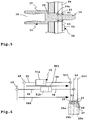
- FIG. 3 illustrated overall system includes, for example, a motor vehicle 80, at the rear 81 a trailer coupling 70 is arranged. Simplified is a hitch with a fixedly arranged on the motor vehicle 80 or, for example, a this attachable coupling arm 72 shown. To a coupling element 71, for example a coupling ball, a trailer 90 can be coupled.
- the coupling arm 72 could also be mounted on the rear end 81 of the motor vehicle 80 by means of a bearing between a position of use intended for pulling the trailer 90 and a position of use projecting rearward of the rear end 81 and a position of disabling use closer to the rear end 81.
- the trailer 90 has, for example, a chassis 91, from which a drawbar 92 protrudes.
- a tow ball coupling 93 is arranged, which can be coupled to the coupling element 71.
- the trailer 90 has electrical trailer components 94, such as a lighting or the like, which are electrically driven via an electrical line 96 or supplied with electrical energy. Front on the line 96 there is a trailer connector 95.
- the trailer connector 95 has in a conventional manner a connector housing 97, projecting from the plug-in projections designed as plug-in contacts 98.
- These plug contacts 98 are, for example, seven plug contacts in accordance with DIN 1724 or thirteen plug contacts in accordance with ISO 11446.
- a plug contact device 10 For electrical connection of the trailer 90 to an electrical system 82 of the motor vehicle 80 is a plug contact device 10.
- the plug contact device 10 is connected via a connecting cable 27 to the electrical system 82, for example, connected to a connected to the electrical system 82 control unit for the trailer 90.
- the plug-in contact device 10 has a socket housing 11 whose peripheral wall 12 and front wall 15 define an interior 14. On the front wall 15 are passage openings 13 for the plug contacts 98. About a pivot bearing 17 is in a conventional manner a lid 18 pivotally, in particular loaded by a spring in the direction of its closed position, in which the front wall 15 is covered stored. On the socket housing 11 are still passage openings 16 which can be penetrated by screws or other fasteners, not shown, to the plug contact device 10 on a support (not shown), which is arranged at the rear 81 of the motor vehicle 80, to be attached.
- connection contacts 33 comprise, for example, contact bodies 37, where sockets 38 are provided for the plug contacts 98.
- sockets 38 are provided for the plug contacts 98.
- seven sockets 38 according to DIN 1724 or thirteen sockets 38 according to ISO 11446 are provided.
- connection contacts 33 project in front of a front side 31 of a trailer contact carrier 34.
- the trailer contact carrier 34 in the present case has a plate-like shape. It may be supported on its outer circumference 35, for example in the interior 14 of the socket housing 11.
- connection cable 27 forms part of a vehicle interface 20 of the plug-in contact device 10. It is also conceivable that the connection cable 27 is detachably connectable to the vehicle interface 20, which in connection with FIG. 6 is still clear.
- the vehicle interface 20 in the present case comprises a vehicle contact carrier 24, on whose front side 21 contact elements 23 are provided for connection to the contact elements 36.
- the contact elements 23 project in front of the front side 21 and are provided, for example, with sockets into which the contact elements 36 designed as plug-in projections can be inserted. But it is also the reverse configuration conceivable, that is, that the contact elements 36 comprise sockets, in which the plug-in projections or other plug contacts designed contact elements 23 are inserted.
- the connecting cable 27 has a plurality of lines or wires, of which lines 28a, 28b are shown by way of example. These lines, including the exemplary lines 28a, 28b, are electrically connected to the contact elements 23 connected.
- seal arrangement 26 on an outer circumference 25 of the vehicle contact carrier 24.
- a seal or a sealing arrangement may also be provided on the other trailer contact carrier 34 of the trailer contact arrangement 30, for example on the outer circumference 35, such that when the contact carriers 24 , 34 in which the socket housing 11 are used, at the same time given a front and back tight seal.
- the aforementioned seals or other seals may also be provided on the inner circumference of the socket housing 11.
- a conductor body 40 which is designed, for example, as a printed circuit board 44 or has such carries the electrical components of the protective circuit 50.
- the conductor body 40 has, for example, electrical on its front side 41, which is the rear side 32 of the trailer contact carrier 34 assigned or facing and / or electronic components 49 which are components of a control device and monitoring device 48 for controlling and monitoring the electric trailer components 94.
- the lighting system of the trailer 90 can be checked or controlled, for example for test purposes.
- the Control device and monitoring device 48 is optional.
- the electrical components 49 include, for example, a microprocessor, logic circuits or the like.
- An outer circumference 45 of the conductor body 40 is expediently identical to the outer circumference 25 or the outer circumference 35 of the trailer contact carrier 34.
- the conductor body 40 in particular the printed circuit board 44, can be sandwiched between the vehicle contact carrier 24 and the trailer contact carrier 34 or arranged in the mounted state.
- a rear side 42 of the printed circuit board 44 is then associated with the front side 21 of the vehicle contact carrier 24, while the rear side 32 of the trailer contact carrier 34 rests against the front side 41 of the printed circuit board 44 or the conductor body 40.
- Additional sealing measures for example an encapsulation or the like, are possible, but not absolutely necessary.
- plug contacts 43 are provided on the conductor body 40, specifically the printed circuit board 44, which comprise through openings 60.
- the contact elements 36 can be inserted through the conductor body 40, in order to come into electrical contact with the opposite contact elements 23 of the vehicle contact carrier 24, in this example, to be plugged.
- contact projections of the contact elements 36 penetrate into sockets of the contact elements 23.
- An electrical contact surface 47 which is suitable for producing an electrical contact with a respective contact body 37 of a contact element 36, extends around one or more, preferably each, of the through openings 60.
- the contact surface 47 is a contact ring.
- a resilient contact element or at least a contact surface is provided on the inner circumference of the passage opening 60.
- the contact surfaces, for example, the collar 46 is located on the contact element 36, for example, the plug-in projection, radially on the outside electrically conductive.
- the contacts are occupied, for example, as follows, in the drawing for the contacts 1-13 or potentials in the protective circuit 50, the designations L1-L13 are selected.
- Contact 1 left blinker Contact 2: Fog light Contact 3: Ground for circuit 1-8
- Contact 4 right blinker Contact 5: Taillight, clearance light, number plate light, right Contact 6: brake-lights Contact 7: Tail light, clearance light, number plate light, left Contact 8: Reversing light
- Contact 9 Power supply (permanent plus) Contact 10: Charging line trailer battery, power supply, ignition switch controlled Contact 11: Ground for circuit via contact 10
- Contact 12 trailer recognition Contact 13: Ground for circuit 9
- the protective circuit 50 now provides, for example, that between one or more of the contacts 1, 2, 4-10 and 12, namely the signal potentials and supply potentials, on the one hand and on the other hand, the ground contacts, for example in the 13-pin occupancy of the contacts 3 and / or 11 and / or 13 is provided in each case a voltage reduction circuit for the reduction of overvoltage or electrostatic charge, eg A stress reduction component 51.
- the voltage reduction component 51 is preferably a diode, in particular a protective diode.
- a diode in particular a protective diode.
- an electronic circuit with active electronic elements, transistors, resistors or the like would also be conceivable.
- one or more of the voltage reduction components 51 to comprise a fuse or another, in particular electronic, quick-acting fuse.
- each passage openings 60 and plug contacts 43 are assigned to the conductor body 40, which in the drawing ( FIG. 4 ) are labeled L1-L13.
- connection cable 27 is not fixedly arranged on the plug-in contact device 10, but via a vehicle contact assembly 29 is detachably connected thereto.
- contacts 65 which can be brought into releasable contact with the vehicle contact arrangement 29 are then located on the connection cable 27.
- the contacts of the contact arrangement 29 and the contacts 65 are plug contacts (sockets and plug-in projections or the like).
- voltage reduction components 51 such as, for example, a voltage reduction component 51b associated with the potential L2 and a voltage reduction component 51a associated with the potential L4
- the voltage reduction components 51a and 51b dissipate an electrostatic voltage US1 or US2, which may possibly occur at the potentials L2 and L4, for example due to electrostatic charging of the trailer 90.
- the in FIG. 4 shown conductor body 40 has a circuit board 144 which has a slightly different outer peripheral contour as the circuit board 44.
- the anti-rotation contours 46 provided on the printed circuit board 44 on the outer circumference correspond with corresponding anti-rotation contours on the outer circumference 25 of the vehicle contact carrier 24, so that the two components are arranged in the mutually adjacent state (see FIG. 2 ) are the same shape on the outer circumference and in the socket housing 11, for example, can be recorded against rotation.
Landscapes
- Engineering & Computer Science (AREA)
- Microelectronics & Electronic Packaging (AREA)
- Coupling Device And Connection With Printed Circuit (AREA)
- Details Of Connecting Devices For Male And Female Coupling (AREA)
Priority Applications (1)
| Application Number | Priority Date | Filing Date | Title |
|---|---|---|---|
| EP21171994.3A EP3883067A1 (fr) | 2013-12-11 | 2014-11-14 | Dispositif de contact à fiche pour un accouplement de remorque |
Applications Claiming Priority (3)
| Application Number | Priority Date | Filing Date | Title |
|---|---|---|---|
| DE102013020506 | 2013-12-11 | ||
| DE102014003672.3A DE102014003672A1 (de) | 2013-12-11 | 2014-03-14 | Steckkontakteinrichtung für eine Anhängekupplung |
| EP14003847.2A EP2884599B1 (fr) | 2013-12-11 | 2014-11-14 | Dispositif de contact à fiche pour un attelage |
Related Parent Applications (3)
| Application Number | Title | Priority Date | Filing Date |
|---|---|---|---|
| EP14003847.2A Division-Into EP2884599B1 (fr) | 2013-12-11 | 2014-11-14 | Dispositif de contact à fiche pour un attelage |
| EP14003847.2A Division EP2884599B1 (fr) | 2013-12-11 | 2014-11-14 | Dispositif de contact à fiche pour un attelage |
| EP14003847.2A Previously-Filed-Application EP2884599B1 (fr) | 2013-12-11 | 2014-11-14 | Dispositif de contact à fiche pour un attelage |
Related Child Applications (2)
| Application Number | Title | Priority Date | Filing Date |
|---|---|---|---|
| EP21171994.3A Division EP3883067A1 (fr) | 2013-12-11 | 2014-11-14 | Dispositif de contact à fiche pour un accouplement de remorque |
| EP21171994.3A Division-Into EP3883067A1 (fr) | 2013-12-11 | 2014-11-14 | Dispositif de contact à fiche pour un accouplement de remorque |
Publications (2)
| Publication Number | Publication Date |
|---|---|
| EP3407437A1 true EP3407437A1 (fr) | 2018-11-28 |
| EP3407437B1 EP3407437B1 (fr) | 2021-06-09 |
Family
ID=51945676
Family Applications (3)
| Application Number | Title | Priority Date | Filing Date |
|---|---|---|---|
| EP18181574.7A Active EP3407437B1 (fr) | 2013-12-11 | 2014-11-14 | Dispositif de contact à fiche pour un attelage |
| EP21171994.3A Withdrawn EP3883067A1 (fr) | 2013-12-11 | 2014-11-14 | Dispositif de contact à fiche pour un accouplement de remorque |
| EP14003847.2A Active EP2884599B1 (fr) | 2013-12-11 | 2014-11-14 | Dispositif de contact à fiche pour un attelage |
Family Applications After (2)
| Application Number | Title | Priority Date | Filing Date |
|---|---|---|---|
| EP21171994.3A Withdrawn EP3883067A1 (fr) | 2013-12-11 | 2014-11-14 | Dispositif de contact à fiche pour un accouplement de remorque |
| EP14003847.2A Active EP2884599B1 (fr) | 2013-12-11 | 2014-11-14 | Dispositif de contact à fiche pour un attelage |
Country Status (2)
| Country | Link |
|---|---|
| EP (3) | EP3407437B1 (fr) |
| DE (1) | DE102014003672A1 (fr) |
Families Citing this family (5)
| Publication number | Priority date | Publication date | Assignee | Title |
|---|---|---|---|---|
| DE102015204423A1 (de) * | 2015-03-12 | 2016-09-15 | Bayerische Motoren Werke Aktiengesellschaft | ESD Schutzvorrichtung für einen Anhänger und/oder für ein Zugfahrzeug |
| US10780818B2 (en) | 2018-12-12 | 2020-09-22 | Bendix Commerical Vehicle Systems Llc | Tri-state trailer pigtail |
| DE102020117030A1 (de) | 2020-06-29 | 2021-12-30 | Ims Connector Systems Gmbh | Elektrischer Steckverbinder |
| US12059964B2 (en) * | 2021-12-09 | 2024-08-13 | Robert Theodore Derstadt | Charging adapter and mobile power supply |
| EP4431315A1 (fr) | 2023-03-15 | 2024-09-18 | ConWys AG | Système de raccordement électrique et électronique d'une remorque à un véhicule |
Citations (11)
| Publication number | Priority date | Publication date | Assignee | Title |
|---|---|---|---|---|
| US4707049A (en) * | 1986-11-03 | 1987-11-17 | Amphenol Corporation | Electrical connector having transient protection |
| US4729743A (en) * | 1985-07-26 | 1988-03-08 | Amp Incorporated | Filtered electrical connector |
| DE19930345A1 (de) | 1999-07-02 | 2001-01-04 | Volta Kraftfahrzeug Elektrozub | Steckdose für Fahrzeuganhänger mit elektronischen Bauteilen |
| EP1148600A1 (fr) | 2000-04-21 | 2001-10-24 | MENBER'S S.p.A. | Adaptateur pour la connexion électrique entre une prise mâle et un connecteur femelle |
| DE20115252U1 (de) | 2000-09-29 | 2002-01-17 | Volkswagen Bordnetze GmbH, 38444 Wolfsburg | Anhängersteckdose |
| US20020125771A1 (en) * | 2001-03-06 | 2002-09-12 | Gary Kaminski | Electrical interface device for towing |
| DE102004032367A1 (de) * | 2004-06-30 | 2006-01-26 | Robert Bosch Gmbh | Elektrisches Steckverbindungselement mit ESD-Schutz |
| DE102005004958A1 (de) | 2005-02-02 | 2006-08-10 | Amphenol-Tuchel Electronics Gmbh | Störschutzvorrichtung für Leitungssätze |
| EP2269845A2 (fr) * | 2009-07-03 | 2011-01-05 | WESTFALIA - Automotive GmbH | Prise d'attelage |
| US20120094509A1 (en) * | 2010-10-14 | 2012-04-19 | Tyco Electronics Corporation | Connector system and assembly having integrated protection circuitry |
| US8344541B1 (en) * | 2007-03-14 | 2013-01-01 | Yazaki North America, Inc. | Reverse current protection methods and systems for trailer tow |
-
2014
- 2014-03-14 DE DE102014003672.3A patent/DE102014003672A1/de not_active Withdrawn
- 2014-11-14 EP EP18181574.7A patent/EP3407437B1/fr active Active
- 2014-11-14 EP EP21171994.3A patent/EP3883067A1/fr not_active Withdrawn
- 2014-11-14 EP EP14003847.2A patent/EP2884599B1/fr active Active
Patent Citations (11)
| Publication number | Priority date | Publication date | Assignee | Title |
|---|---|---|---|---|
| US4729743A (en) * | 1985-07-26 | 1988-03-08 | Amp Incorporated | Filtered electrical connector |
| US4707049A (en) * | 1986-11-03 | 1987-11-17 | Amphenol Corporation | Electrical connector having transient protection |
| DE19930345A1 (de) | 1999-07-02 | 2001-01-04 | Volta Kraftfahrzeug Elektrozub | Steckdose für Fahrzeuganhänger mit elektronischen Bauteilen |
| EP1148600A1 (fr) | 2000-04-21 | 2001-10-24 | MENBER'S S.p.A. | Adaptateur pour la connexion électrique entre une prise mâle et un connecteur femelle |
| DE20115252U1 (de) | 2000-09-29 | 2002-01-17 | Volkswagen Bordnetze GmbH, 38444 Wolfsburg | Anhängersteckdose |
| US20020125771A1 (en) * | 2001-03-06 | 2002-09-12 | Gary Kaminski | Electrical interface device for towing |
| DE102004032367A1 (de) * | 2004-06-30 | 2006-01-26 | Robert Bosch Gmbh | Elektrisches Steckverbindungselement mit ESD-Schutz |
| DE102005004958A1 (de) | 2005-02-02 | 2006-08-10 | Amphenol-Tuchel Electronics Gmbh | Störschutzvorrichtung für Leitungssätze |
| US8344541B1 (en) * | 2007-03-14 | 2013-01-01 | Yazaki North America, Inc. | Reverse current protection methods and systems for trailer tow |
| EP2269845A2 (fr) * | 2009-07-03 | 2011-01-05 | WESTFALIA - Automotive GmbH | Prise d'attelage |
| US20120094509A1 (en) * | 2010-10-14 | 2012-04-19 | Tyco Electronics Corporation | Connector system and assembly having integrated protection circuitry |
Non-Patent Citations (1)
| Title |
|---|
| ANONYMOUS: "Leistungshalbleiter", WIKIPEDIA, 15 October 2020 (2020-10-15), XP055766178, Retrieved from the Internet <URL:https://de.wikipedia.org/wiki/Leistungshalbleiter> |
Also Published As
| Publication number | Publication date |
|---|---|
| EP2884599B1 (fr) | 2018-08-15 |
| EP2884599A1 (fr) | 2015-06-17 |
| DE102014003672A1 (de) | 2015-06-11 |
| EP3883067A1 (fr) | 2021-09-22 |
| EP3407437B1 (fr) | 2021-06-09 |
Similar Documents
| Publication | Publication Date | Title |
|---|---|---|
| EP2904667B1 (fr) | Système modulaire pour un dispositif de chargement, dispositif de chargement ainsi que véhicule comportant un dispositif de chargement réalisé à partir dudit système modulaire | |
| EP2884599B1 (fr) | Dispositif de contact à fiche pour un attelage | |
| EP2423029B1 (fr) | Dispositif mobile de chargement pour chariot de manutention électrique, élément de connexion électrique et chargeur pour chariot électrique | |
| EP2070311A1 (fr) | Systeme de camera modulaire | |
| EP2671740B1 (fr) | Prise d'attelage | |
| DE202017102886U1 (de) | Adapterstecker für ein Ladesystem zum Aufladen eines Elektrofahrzeugs | |
| DE102008054365A1 (de) | Anschlussanordnung für ein Anhängefahrzeug und Anhängefahrzeug | |
| EP2722262A2 (fr) | Unité centrale pour entraînement de manoeuvre | |
| DE102006009936A1 (de) | Anordnung zur Stromverteilung sowie deren Kontaktierung und Absicherung der abgehenden Leitungen | |
| EP0176677B1 (fr) | Connexion à fiche multipôle séparable pour le transfert de courants électriques utilisée par exemple dans des automobiles | |
| DE102020124092B4 (de) | Steckverbinderanordnung zum Verbinden einer elektrischen Leitung mit einem elektrischen Bauelement | |
| DE202010015919U1 (de) | Schaltungsanordnung für ein Fahrzeug | |
| DE202021106965U1 (de) | Steckverbinder für eine kombinierte elektrische Verbindung und Datenverbindung | |
| DE102016210433A1 (de) | Verteilergehäuse für einen Fahrzeuganhänger | |
| DE102017006979A1 (de) | Hochvolt-Anordnung für ein Kraftfahrzeug mit Signalübertragung über einen Hochvolt-Schirm | |
| DE20115252U1 (de) | Anhängersteckdose | |
| EP3944972A1 (fr) | Appareil de raccordement de remorque à fonctionnement amélioré des feux antibrouillard arrière | |
| EP3944973A1 (fr) | Appareil de raccordement de remorque à surveillance de captage du courant | |
| DE10335264B4 (de) | Vorrichtung zur Stromversorgung wenigstens eines elektrischen Verbrauchers, der in einem von einem Zugfahrzeug gezogenen Trailer angeordnet ist | |
| DE102023104046B4 (de) | Kraftfahrzeug und Ladeeinrichtung für ein Kraftfahrzeug zum elektrischen Laden eines Energiespeichers des Kraftfahrzeugs | |
| DE102022132335A1 (de) | Fahrzeugkomponente für ein wenigstens teilweise elektrisch angetriebenes Kraftfahrzeug mit wenigstens einer Ladeschnittstelle | |
| DE202016102332U1 (de) | 12 V Anhängersteckdose für Kraftfahrzeug mit 24 V Bordnetz | |
| EP2364259A1 (fr) | Système de capteur(s) de distance pour véhicule tracté et véhicule tracté | |
| DE102015204423A1 (de) | ESD Schutzvorrichtung für einen Anhänger und/oder für ein Zugfahrzeug | |
| DE102023132202A1 (de) | Befestigung von Steuergeräten |
Legal Events
| Date | Code | Title | Description |
|---|---|---|---|
| PUAI | Public reference made under article 153(3) epc to a published international application that has entered the european phase |
Free format text: ORIGINAL CODE: 0009012 |
|
| STAA | Information on the status of an ep patent application or granted ep patent |
Free format text: STATUS: THE APPLICATION HAS BEEN PUBLISHED |
|
| AC | Divisional application: reference to earlier application |
Ref document number: 2884599 Country of ref document: EP Kind code of ref document: P |
|
| AK | Designated contracting states |
Kind code of ref document: A1 Designated state(s): AL AT BE BG CH CY CZ DE DK EE ES FI FR GB GR HR HU IE IS IT LI LT LU LV MC MK MT NL NO PL PT RO RS SE SI SK SM TR |
|
| STAA | Information on the status of an ep patent application or granted ep patent |
Free format text: STATUS: REQUEST FOR EXAMINATION WAS MADE |
|
| 17P | Request for examination filed |
Effective date: 20190522 |
|
| RBV | Designated contracting states (corrected) |
Designated state(s): AL AT BE BG CH CY CZ DE DK EE ES FI FR GB GR HR HU IE IS IT LI LT LU LV MC MK MT NL NO PL PT RO RS SE SI SK SM TR |
|
| STAA | Information on the status of an ep patent application or granted ep patent |
Free format text: STATUS: EXAMINATION IS IN PROGRESS |
|
| 17Q | First examination report despatched |
Effective date: 20190918 |
|
| TPAC | Observations filed by third parties |
Free format text: ORIGINAL CODE: EPIDOSNTIPA |
|
| TPAA | Information related to observations by third parties modified |
Free format text: ORIGINAL CODE: EPIDOSCTIPA |
|
| TPAA | Information related to observations by third parties modified |
Free format text: ORIGINAL CODE: EPIDOSCTIPA |
|
| GRAP | Despatch of communication of intention to grant a patent |
Free format text: ORIGINAL CODE: EPIDOSNIGR1 |
|
| STAA | Information on the status of an ep patent application or granted ep patent |
Free format text: STATUS: GRANT OF PATENT IS INTENDED |
|
| INTG | Intention to grant announced |
Effective date: 20210112 |
|
| GRAS | Grant fee paid |
Free format text: ORIGINAL CODE: EPIDOSNIGR3 |
|
| GRAA | (expected) grant |
Free format text: ORIGINAL CODE: 0009210 |
|
| STAA | Information on the status of an ep patent application or granted ep patent |
Free format text: STATUS: THE PATENT HAS BEEN GRANTED |
|
| AC | Divisional application: reference to earlier application |
Ref document number: 2884599 Country of ref document: EP Kind code of ref document: P |
|
| AK | Designated contracting states |
Kind code of ref document: B1 Designated state(s): AL AT BE BG CH CY CZ DE DK EE ES FI FR GB GR HR HU IE IS IT LI LT LU LV MC MK MT NL NO PL PT RO RS SE SI SK SM TR |
|
| REG | Reference to a national code |
Ref country code: GB Ref legal event code: FG4D Free format text: NOT ENGLISH |
|
| REG | Reference to a national code |
Ref country code: CH Ref legal event code: EP Ref country code: AT Ref legal event code: REF Ref document number: 1401254 Country of ref document: AT Kind code of ref document: T Effective date: 20210615 |
|
| REG | Reference to a national code |
Ref country code: DE Ref legal event code: R096 Ref document number: 502014015664 Country of ref document: DE |
|
| REG | Reference to a national code |
Ref country code: IE Ref legal event code: FG4D Free format text: LANGUAGE OF EP DOCUMENT: GERMAN |
|
| REG | Reference to a national code |
Ref country code: LT Ref legal event code: MG9D |
|
| PG25 | Lapsed in a contracting state [announced via postgrant information from national office to epo] |
Ref country code: FI Free format text: LAPSE BECAUSE OF FAILURE TO SUBMIT A TRANSLATION OF THE DESCRIPTION OR TO PAY THE FEE WITHIN THE PRESCRIBED TIME-LIMIT Effective date: 20210609 Ref country code: HR Free format text: LAPSE BECAUSE OF FAILURE TO SUBMIT A TRANSLATION OF THE DESCRIPTION OR TO PAY THE FEE WITHIN THE PRESCRIBED TIME-LIMIT Effective date: 20210609 Ref country code: LT Free format text: LAPSE BECAUSE OF FAILURE TO SUBMIT A TRANSLATION OF THE DESCRIPTION OR TO PAY THE FEE WITHIN THE PRESCRIBED TIME-LIMIT Effective date: 20210609 Ref country code: BG Free format text: LAPSE BECAUSE OF FAILURE TO SUBMIT A TRANSLATION OF THE DESCRIPTION OR TO PAY THE FEE WITHIN THE PRESCRIBED TIME-LIMIT Effective date: 20210909 |
|
| REG | Reference to a national code |
Ref country code: NL Ref legal event code: MP Effective date: 20210609 |
|
| PG25 | Lapsed in a contracting state [announced via postgrant information from national office to epo] |
Ref country code: LV Free format text: LAPSE BECAUSE OF FAILURE TO SUBMIT A TRANSLATION OF THE DESCRIPTION OR TO PAY THE FEE WITHIN THE PRESCRIBED TIME-LIMIT Effective date: 20210609 Ref country code: NO Free format text: LAPSE BECAUSE OF FAILURE TO SUBMIT A TRANSLATION OF THE DESCRIPTION OR TO PAY THE FEE WITHIN THE PRESCRIBED TIME-LIMIT Effective date: 20210909 Ref country code: RS Free format text: LAPSE BECAUSE OF FAILURE TO SUBMIT A TRANSLATION OF THE DESCRIPTION OR TO PAY THE FEE WITHIN THE PRESCRIBED TIME-LIMIT Effective date: 20210609 Ref country code: SE Free format text: LAPSE BECAUSE OF FAILURE TO SUBMIT A TRANSLATION OF THE DESCRIPTION OR TO PAY THE FEE WITHIN THE PRESCRIBED TIME-LIMIT Effective date: 20210609 Ref country code: GR Free format text: LAPSE BECAUSE OF FAILURE TO SUBMIT A TRANSLATION OF THE DESCRIPTION OR TO PAY THE FEE WITHIN THE PRESCRIBED TIME-LIMIT Effective date: 20210910 |
|
| PG25 | Lapsed in a contracting state [announced via postgrant information from national office to epo] |
Ref country code: RO Free format text: LAPSE BECAUSE OF FAILURE TO SUBMIT A TRANSLATION OF THE DESCRIPTION OR TO PAY THE FEE WITHIN THE PRESCRIBED TIME-LIMIT Effective date: 20210609 Ref country code: NL Free format text: LAPSE BECAUSE OF FAILURE TO SUBMIT A TRANSLATION OF THE DESCRIPTION OR TO PAY THE FEE WITHIN THE PRESCRIBED TIME-LIMIT Effective date: 20210609 Ref country code: PT Free format text: LAPSE BECAUSE OF FAILURE TO SUBMIT A TRANSLATION OF THE DESCRIPTION OR TO PAY THE FEE WITHIN THE PRESCRIBED TIME-LIMIT Effective date: 20211011 Ref country code: CZ Free format text: LAPSE BECAUSE OF FAILURE TO SUBMIT A TRANSLATION OF THE DESCRIPTION OR TO PAY THE FEE WITHIN THE PRESCRIBED TIME-LIMIT Effective date: 20210609 Ref country code: SK Free format text: LAPSE BECAUSE OF FAILURE TO SUBMIT A TRANSLATION OF THE DESCRIPTION OR TO PAY THE FEE WITHIN THE PRESCRIBED TIME-LIMIT Effective date: 20210609 Ref country code: SM Free format text: LAPSE BECAUSE OF FAILURE TO SUBMIT A TRANSLATION OF THE DESCRIPTION OR TO PAY THE FEE WITHIN THE PRESCRIBED TIME-LIMIT Effective date: 20210609 Ref country code: EE Free format text: LAPSE BECAUSE OF FAILURE TO SUBMIT A TRANSLATION OF THE DESCRIPTION OR TO PAY THE FEE WITHIN THE PRESCRIBED TIME-LIMIT Effective date: 20210609 Ref country code: ES Free format text: LAPSE BECAUSE OF FAILURE TO SUBMIT A TRANSLATION OF THE DESCRIPTION OR TO PAY THE FEE WITHIN THE PRESCRIBED TIME-LIMIT Effective date: 20210609 |
|
| PG25 | Lapsed in a contracting state [announced via postgrant information from national office to epo] |
Ref country code: PL Free format text: LAPSE BECAUSE OF FAILURE TO SUBMIT A TRANSLATION OF THE DESCRIPTION OR TO PAY THE FEE WITHIN THE PRESCRIBED TIME-LIMIT Effective date: 20210609 |
|
| REG | Reference to a national code |
Ref country code: DE Ref legal event code: R097 Ref document number: 502014015664 Country of ref document: DE |
|
| PLBE | No opposition filed within time limit |
Free format text: ORIGINAL CODE: 0009261 |
|
| STAA | Information on the status of an ep patent application or granted ep patent |
Free format text: STATUS: NO OPPOSITION FILED WITHIN TIME LIMIT |
|
| PG25 | Lapsed in a contracting state [announced via postgrant information from national office to epo] |
Ref country code: DK Free format text: LAPSE BECAUSE OF FAILURE TO SUBMIT A TRANSLATION OF THE DESCRIPTION OR TO PAY THE FEE WITHIN THE PRESCRIBED TIME-LIMIT Effective date: 20210609 |
|
| 26N | No opposition filed |
Effective date: 20220310 |
|
| PG25 | Lapsed in a contracting state [announced via postgrant information from national office to epo] |
Ref country code: AL Free format text: LAPSE BECAUSE OF FAILURE TO SUBMIT A TRANSLATION OF THE DESCRIPTION OR TO PAY THE FEE WITHIN THE PRESCRIBED TIME-LIMIT Effective date: 20210609 |
|
| PG25 | Lapsed in a contracting state [announced via postgrant information from national office to epo] |
Ref country code: MC Free format text: LAPSE BECAUSE OF FAILURE TO SUBMIT A TRANSLATION OF THE DESCRIPTION OR TO PAY THE FEE WITHIN THE PRESCRIBED TIME-LIMIT Effective date: 20210609 |
|
| REG | Reference to a national code |
Ref country code: CH Ref legal event code: PL |
|
| GBPC | Gb: european patent ceased through non-payment of renewal fee |
Effective date: 20211114 |
|
| PG25 | Lapsed in a contracting state [announced via postgrant information from national office to epo] |
Ref country code: LU Free format text: LAPSE BECAUSE OF NON-PAYMENT OF DUE FEES Effective date: 20211114 Ref country code: IT Free format text: LAPSE BECAUSE OF FAILURE TO SUBMIT A TRANSLATION OF THE DESCRIPTION OR TO PAY THE FEE WITHIN THE PRESCRIBED TIME-LIMIT Effective date: 20210609 Ref country code: BE Free format text: LAPSE BECAUSE OF NON-PAYMENT OF DUE FEES Effective date: 20211130 |
|
| REG | Reference to a national code |
Ref country code: BE Ref legal event code: MM Effective date: 20211130 |
|
| PG25 | Lapsed in a contracting state [announced via postgrant information from national office to epo] |
Ref country code: IE Free format text: LAPSE BECAUSE OF NON-PAYMENT OF DUE FEES Effective date: 20211114 Ref country code: GB Free format text: LAPSE BECAUSE OF NON-PAYMENT OF DUE FEES Effective date: 20211114 |
|
| REG | Reference to a national code |
Ref country code: AT Ref legal event code: MM01 Ref document number: 1401254 Country of ref document: AT Kind code of ref document: T Effective date: 20211114 |
|
| PG25 | Lapsed in a contracting state [announced via postgrant information from national office to epo] |
Ref country code: AT Free format text: LAPSE BECAUSE OF NON-PAYMENT OF DUE FEES Effective date: 20211114 |
|
| PG25 | Lapsed in a contracting state [announced via postgrant information from national office to epo] |
Ref country code: CY Free format text: LAPSE BECAUSE OF FAILURE TO SUBMIT A TRANSLATION OF THE DESCRIPTION OR TO PAY THE FEE WITHIN THE PRESCRIBED TIME-LIMIT Effective date: 20210609 |
|
| PG25 | Lapsed in a contracting state [announced via postgrant information from national office to epo] |
Ref country code: LI Free format text: LAPSE BECAUSE OF NON-PAYMENT OF DUE FEES Effective date: 20220630 Ref country code: HU Free format text: LAPSE BECAUSE OF FAILURE TO SUBMIT A TRANSLATION OF THE DESCRIPTION OR TO PAY THE FEE WITHIN THE PRESCRIBED TIME-LIMIT; INVALID AB INITIO Effective date: 20141114 Ref country code: CH Free format text: LAPSE BECAUSE OF NON-PAYMENT OF DUE FEES Effective date: 20220630 |
|
| PG25 | Lapsed in a contracting state [announced via postgrant information from national office to epo] |
Ref country code: MK Free format text: LAPSE BECAUSE OF FAILURE TO SUBMIT A TRANSLATION OF THE DESCRIPTION OR TO PAY THE FEE WITHIN THE PRESCRIBED TIME-LIMIT Effective date: 20210609 |
|
| PG25 | Lapsed in a contracting state [announced via postgrant information from national office to epo] |
Ref country code: TR Free format text: LAPSE BECAUSE OF FAILURE TO SUBMIT A TRANSLATION OF THE DESCRIPTION OR TO PAY THE FEE WITHIN THE PRESCRIBED TIME-LIMIT Effective date: 20210609 |
|
| PG25 | Lapsed in a contracting state [announced via postgrant information from national office to epo] |
Ref country code: MT Free format text: LAPSE BECAUSE OF FAILURE TO SUBMIT A TRANSLATION OF THE DESCRIPTION OR TO PAY THE FEE WITHIN THE PRESCRIBED TIME-LIMIT Effective date: 20210609 |
|
| PGFP | Annual fee paid to national office [announced via postgrant information from national office to epo] |
Ref country code: FR Payment date: 20251226 Year of fee payment: 12 |
|
| PGFP | Annual fee paid to national office [announced via postgrant information from national office to epo] |
Ref country code: DE Payment date: 20251229 Year of fee payment: 12 |