EP3407471A1 - Motor-getriebe-verbindungsanordnung, insbesondere zur verwendung in fahrzeugen - Google Patents
Motor-getriebe-verbindungsanordnung, insbesondere zur verwendung in fahrzeugen Download PDFInfo
- Publication number
- EP3407471A1 EP3407471A1 EP17172633.4A EP17172633A EP3407471A1 EP 3407471 A1 EP3407471 A1 EP 3407471A1 EP 17172633 A EP17172633 A EP 17172633A EP 3407471 A1 EP3407471 A1 EP 3407471A1
- Authority
- EP
- European Patent Office
- Prior art keywords
- pot
- engine
- motor
- brush holder
- transmission
- Prior art date
- Legal status (The legal status is an assumption and is not a legal conclusion. Google has not performed a legal analysis and makes no representation as to the accuracy of the status listed.)
- Granted
Links
Images
Classifications
-
- H—ELECTRICITY
- H02—GENERATION; CONVERSION OR DISTRIBUTION OF ELECTRIC POWER
- H02K—DYNAMO-ELECTRIC MACHINES
- H02K7/00—Arrangements for handling mechanical energy structurally associated with dynamo-electric machines, e.g. structural association with mechanical driving motors or auxiliary dynamo-electric machines
- H02K7/10—Structural association with clutches, brakes, gears, pulleys or mechanical starters
- H02K7/116—Structural association with clutches, brakes, gears, pulleys or mechanical starters with gears
-
- H—ELECTRICITY
- H02—GENERATION; CONVERSION OR DISTRIBUTION OF ELECTRIC POWER
- H02K—DYNAMO-ELECTRIC MACHINES
- H02K5/00—Casings; Enclosures; Supports
- H02K5/04—Casings or enclosures characterised by the shape, form or construction thereof
- H02K5/14—Means for supporting or protecting brushes or brush holders
- H02K5/143—Means for supporting or protecting brushes or brush holders for cooperation with commutators
- H02K5/145—Fixedly supported brushes or brush holders, e.g. leaf or leaf-mounted brushes
-
- B—PERFORMING OPERATIONS; TRANSPORTING
- B60—VEHICLES IN GENERAL
- B60K—ARRANGEMENT OR MOUNTING OF PROPULSION UNITS OR OF TRANSMISSIONS IN VEHICLES; ARRANGEMENT OR MOUNTING OF PLURAL DIVERSE PRIME-MOVERS IN VEHICLES; AUXILIARY DRIVES FOR VEHICLES; INSTRUMENTATION OR DASHBOARDS FOR VEHICLES; ARRANGEMENTS IN CONNECTION WITH COOLING, AIR INTAKE, GAS EXHAUST OR FUEL SUPPLY OF PROPULSION UNITS IN VEHICLES
- B60K17/00—Arrangement or mounting of transmissions in vehicles
- B60K17/04—Arrangement or mounting of transmissions in vehicles characterised by arrangement, location or kind of gearing
- B60K17/06—Arrangement or mounting of transmissions in vehicles characterised by arrangement, location or kind of gearing of change-speed gearing
- B60K17/08—Arrangement or mounting of transmissions in vehicles characterised by arrangement, location or kind of gearing of change-speed gearing of mechanical type
-
- B—PERFORMING OPERATIONS; TRANSPORTING
- B60—VEHICLES IN GENERAL
- B60J—WINDOWS, WINDSCREENS, NON-FIXED ROOFS, DOORS, OR SIMILAR DEVICES FOR VEHICLES; REMOVABLE EXTERNAL PROTECTIVE COVERINGS SPECIALLY ADAPTED FOR VEHICLES
- B60J7/00—Non-fixed roofs; Roofs with movable panels, e.g. rotary sunroofs
- B60J7/02—Non-fixed roofs; Roofs with movable panels, e.g. rotary sunroofs of sliding type, e.g. comprising guide shoes
- B60J7/04—Non-fixed roofs; Roofs with movable panels, e.g. rotary sunroofs of sliding type, e.g. comprising guide shoes with rigid plate-like element or elements, e.g. open roofs with harmonica-type folding rigid panels
- B60J7/057—Driving or actuating arrangements e.g. manually operated levers or knobs
-
- F—MECHANICAL ENGINEERING; LIGHTING; HEATING; WEAPONS; BLASTING
- F16—ENGINEERING ELEMENTS AND UNITS; GENERAL MEASURES FOR PRODUCING AND MAINTAINING EFFECTIVE FUNCTIONING OF MACHINES OR INSTALLATIONS; THERMAL INSULATION IN GENERAL
- F16H—GEARING
- F16H57/00—General details of gearing
- F16H57/02—Gearboxes; Mounting gearing therein
- F16H57/025—Support of gearboxes, e.g. torque arms, or attachment to other devices
-
- H—ELECTRICITY
- H02—GENERATION; CONVERSION OR DISTRIBUTION OF ELECTRIC POWER
- H02K—DYNAMO-ELECTRIC MACHINES
- H02K5/00—Casings; Enclosures; Supports
- H02K5/04—Casings or enclosures characterised by the shape, form or construction thereof
- H02K5/14—Means for supporting or protecting brushes or brush holders
-
- H—ELECTRICITY
- H02—GENERATION; CONVERSION OR DISTRIBUTION OF ELECTRIC POWER
- H02K—DYNAMO-ELECTRIC MACHINES
- H02K5/00—Casings; Enclosures; Supports
- H02K5/04—Casings or enclosures characterised by the shape, form or construction thereof
- H02K5/14—Means for supporting or protecting brushes or brush holders
- H02K5/143—Means for supporting or protecting brushes or brush holders for cooperation with commutators
-
- H—ELECTRICITY
- H02—GENERATION; CONVERSION OR DISTRIBUTION OF ELECTRIC POWER
- H02K—DYNAMO-ELECTRIC MACHINES
- H02K5/00—Casings; Enclosures; Supports
- H02K5/04—Casings or enclosures characterised by the shape, form or construction thereof
- H02K5/15—Mounting arrangements for bearing-shields or end plates
-
- H—ELECTRICITY
- H02—GENERATION; CONVERSION OR DISTRIBUTION OF ELECTRIC POWER
- H02K—DYNAMO-ELECTRIC MACHINES
- H02K7/00—Arrangements for handling mechanical energy structurally associated with dynamo-electric machines, e.g. structural association with mechanical driving motors or auxiliary dynamo-electric machines
- H02K7/10—Structural association with clutches, brakes, gears, pulleys or mechanical starters
- H02K7/116—Structural association with clutches, brakes, gears, pulleys or mechanical starters with gears
- H02K7/1163—Structural association with clutches, brakes, gears, pulleys or mechanical starters with gears where at least two gears have non-parallel axes without having orbital motion
- H02K7/1166—Structural association with clutches, brakes, gears, pulleys or mechanical starters with gears where at least two gears have non-parallel axes without having orbital motion comprising worm and worm-wheel
-
- B—PERFORMING OPERATIONS; TRANSPORTING
- B60—VEHICLES IN GENERAL
- B60J—WINDOWS, WINDSCREENS, NON-FIXED ROOFS, DOORS, OR SIMILAR DEVICES FOR VEHICLES; REMOVABLE EXTERNAL PROTECTIVE COVERINGS SPECIALLY ADAPTED FOR VEHICLES
- B60J7/00—Non-fixed roofs; Roofs with movable panels, e.g. rotary sunroofs
- B60J7/02—Non-fixed roofs; Roofs with movable panels, e.g. rotary sunroofs of sliding type, e.g. comprising guide shoes
- B60J7/04—Non-fixed roofs; Roofs with movable panels, e.g. rotary sunroofs of sliding type, e.g. comprising guide shoes with rigid plate-like element or elements, e.g. open roofs with harmonica-type folding rigid panels
- B60J7/057—Driving or actuating arrangements e.g. manually operated levers or knobs
- B60J7/0573—Driving or actuating arrangements e.g. manually operated levers or knobs power driven arrangements, e.g. electrical
-
- F—MECHANICAL ENGINEERING; LIGHTING; HEATING; WEAPONS; BLASTING
- F16—ENGINEERING ELEMENTS AND UNITS; GENERAL MEASURES FOR PRODUCING AND MAINTAINING EFFECTIVE FUNCTIONING OF MACHINES OR INSTALLATIONS; THERMAL INSULATION IN GENERAL
- F16H—GEARING
- F16H57/00—General details of gearing
- F16H57/02—Gearboxes; Mounting gearing therein
- F16H2057/02034—Gearboxes combined or connected with electric machines
-
- H—ELECTRICITY
- H01—ELECTRIC ELEMENTS
- H01R—ELECTRICALLY-CONDUCTIVE CONNECTIONS; STRUCTURAL ASSOCIATIONS OF A PLURALITY OF MUTUALLY-INSULATED ELECTRICAL CONNECTING ELEMENTS; COUPLING DEVICES; CURRENT COLLECTORS
- H01R39/00—Rotary current collectors, distributors or interrupters
- H01R39/02—Details for dynamo electric machines
- H01R39/38—Brush holders
- H01R39/385—Means for mechanical fixation of the brush holder
Definitions
- the present invention relates to a motor-transmission connecting arrangement, in particular for use in vehicles.
- Engine-transmission link assemblies combine a drive motor, such as an electric motor, and a transmission into a unit.
- the resulting assembly can be pre-assembled by a manufacturer, whereby the installation in a device in which the assembly is to be used, can be simplified.
- a particular embodiment of such devices, where engine-transmission connection assemblies are frequently used, are vehicles.
- the windows and sunroofs were manually opened and closed by turning a crank, electromotive windows are nowadays almost exclusively used for this purpose.
- the engine-gearbox connection assembly When using electric motors, the engine-gearbox connection assembly includes a motor pot for receiving an electric motor, a brush holder for holding brushes of the electric motor, and a gear housing for housing a gearbox. These three components must be aligned relative to each other during assembly and interconnected.
- the brush holder is centered within the motor pot and the gear housing connected via a flange-like connection with the motor pot.
- the connection of the gear housing with the engine pot via screws which are performed by openings which are arranged on radially outwardly projecting portions of the engine pot and the gear housing. Due to these outwardly projecting portions of a certain space must be kept free, which is scarce, especially in vehicles for the reasons mentioned above.
- Object of an embodiment of the present invention is therefore to provide a motor-transmission connection assembly, with which space can be saved and which is easy to manufacture and assemble.
- the engine-transmission connection assembly should allow the most accurate alignment of the engine pot, the brush holder and the gear housing to each other.
- An embodiment of the invention relates to an engine-transmission connecting assembly, in particular for use in vehicles, comprising a motor pot for receiving an electric motor, a brush holder for holding brushes of the electric motor, and a transmission housing for receiving a transmission, wherein the motor pot, the brush holder and the transmission housing can be inserted into one another for connection.
- the engine pot has a number of centering surfaces with which the engine pot comes into contact with both the brush holder and the transmission housing when the engine pot, the brush holder and the gear housing are inserted into each other, whereby the brush holder and the gear housing are aligned concentrically with the engine pot ,
- the number of centering surfaces can in principle be chosen freely. However, it should be noted that in each of the three spatial axes due to manufacturing tolerances only one pair of contact surfaces and mating surfaces per space axis can be effective. In addition, a static overdetermination is to be avoided so that a gap is intentionally provided between two pairs of contact surfaces which could come into contact with each other on purpose. As a result, changes in shape due to temperature fluctuations can be compensated without voltages are introduced into the components concerned.
- the centering of the brush holder and the gear housing with respect to the engine pot is made exclusively on the centering surfaces, which does not limit the mobility along the longitudinal axis of the engine-transmission connection assembly cause, but limit the mobility of the brush holder and the gear housing perpendicular to the longitudinal axis.
- the fact that the centering is performed exclusively on the centering surfaces a summation of the manufacturing tolerances is avoided.
- the brush holder and the gear housing are each centered separately relative to the engine pot, so that the tolerances are added here.
- the brush holder and the gear housing can be arranged in a simple manner very precisely concentric with the engine pot. Noise developments, which are caused by an insufficient concentric arrangement of the engine pot, the brush holder and the gear housing to each other, thereby avoided, so that the drive device, which makes use of the proposed engine-transmission-connection arrangement, can be operated very quietly.
- the motor pot is used in this embodiment as a receptacle, in which the brush holder and the gear housing are inserted.
- the centering surfaces extend within the motor pot, so that the brush holder and the gear housing in the inserted state protrude more or less far into the engine pot, wherein the brush holder in the inserted state can also be completely surrounded by the engine pot.
- the engine-transmission connection arrangement can be made shorter, whereby further space can be saved in the axial direction. Due to the possibility of making the engine pot shorter, it does not have to be deep-drawn so far, which represents a simplification from a manufacturing point of view.
- the modifications that must be made to the brush holder over known variants are significantly small.
- the brush holder only needs to be adjusted so that the contact surfaces of the motor pot can actually make contact with the brush holder.
- the cost of producing the tool required by the injection molding process does not differ from that which has hitherto been used. The difference lies only in the contour of the cavity.
- the basic structure of the brush holder and the gear housing does not need to be changed.
- the brush holder and the gear housing can be manufactured by injection molding, so that large quantities can be produced at a relatively low cost.
- a further embodiment is characterized in that the engine pot has first contact surfaces, with which the engine pot contacts the brush holder, and / or second contact surfaces with which the engine pot comes into contact with the transmission housing when the engine pot, the brush holder and the Gear housing are inserted into each other.
- the first and the second contact surfaces may be designed so that they act with respect to the longitudinal axis of the engine-transmission connection assembly as stop surfaces and limit the mobility of the components relative to each other along the longitudinal axis.
- the first and / or second contact surfaces have no concentric aligning effect of the brush holder and the gear housing with respect to the engine pot. It is advisable to provide first and second mating surfaces in the gear housing, with which the first and / or second contact surfaces come into contact when the engine pot, the brush holder and the gear housing are inserted into each other.
- the brush holder has third contact surfaces, with which the brush holder comes into contact with the transmission housing when the engine pot, the brush holder and the gear housing are inserted into one another. It lends itself here to provide the third contact surfaces with crush ribs, which serve for clearance compensation of the engine-transmission connection assembly along the longitudinal axis. In addition, it makes sense to provide third mating surfaces in the gear housing, with which the third contact surfaces come into contact when the engine pot, the brush holder and the gear housing are inserted into each other.
- the gear housing is used simultaneously to limit the mobility of the brush holder along the longitudinal axis of the engine-transmission-connection assembly, so that no further measures have to be taken.
- the design and assembly are thereby simplified.
- the engine pot and / or the gear housing may have crimping sections for connecting the gearbox housing to the engine pot.
- the engine-transmission connecting assembly has centering surfaces with which the transmission housing contacts both the brush holder and the engine pot when the engine pot, the brush holder and the gear housing are inserted into each other, whereby the brush holder and the motor pot be aligned concentrically with the gear housing.
- An implementation of the invention relates to a sliding roof in a vehicle, comprising a motor-transmission connection arrangement according to one of the previous embodiments.
- an embodiment of the invention relates to the use of a motor-transmission connecting arrangement according to one of the previous embodiments for auxiliary drives in vehicles, in particular in motor vehicles.
- Auxiliary drives are understood to mean drives with which one vehicle part is moved relative to another vehicle part, for example in window regulators, tailgates and seats. Auxiliary drives are not suitable to move the vehicle itself.
- An embodiment of the invention relates to a vehicle, in particular a motor vehicle, comprising engine-transmission connection arrangement according to one of the previous embodiments.
- the advantages and technical effects that can be realized with such a sunroof, the use of the engine-transmission connection assembly and such a vehicle, correspond to those which have been described for the various embodiments of the engine-transmission connection assembly. Due to the fact that the centering is performed exclusively via the centering surfaces, a summation of the tolerances is avoided. Furthermore, a crimping for attaching the gear housing to the engine pot is possible, whereas in the prior art, a screw is necessary.
- the logistics is simplified because the Vercrimpabitese are formed directly on the engine pot and / or on the gear housing and therefore no separate fasteners must be kept.
- the reduced space of the proposed engine-transmission connection assembly is particularly strong advantage.
- the possibility of arranging the brush holder and the gear housing very precisely concentric with the motor pot a very quiet operation of the drive device can be realized, which the Proposed engine-transmission connection arrangement used.
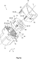
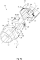
- the engine-transmission connection assembly 10 includes a motor pot 12 for receiving an electric motor, not shown, a brush holder 14, which are not shown brushes are held for the electric motor, and a transmission housing 16 for receiving a transmission, also not shown.
- the engine pot 12 includes first contact surfaces 18, with which the motor pot 12 comes into contact with the brush holder 14 when the brush holder 14 is inserted into the motor pot 12. Furthermore, the engine pot 12 has second contact surfaces 20 with which the engine pot 12 comes into contact with the transmission housing 16 when the transmission housing 16 is inserted into the engine pot 12.
- the brush holder 14 has third contact surfaces 24, with which the brush holder 14 comes into contact with the gear housing 16 when the brush holder 14 and the gear housing 16 are inserted into the motor pot 12.
- the engine pot includes 12 centering surfaces 50 which act in the x direction, and centering surfaces 52 which act in the y direction, with which the motor pot 12 with both the brush holder 14 and the gear housing 16 comes into contact when the Brush holder 14 and the gear housing 16 are inserted into the motor pot 12.
- the brush holder 14 and the gear housing 16 have first mating surfaces 26, second mating surfaces 28 and third mating surfaces 30, with which they contact the one or more first contact surfaces 18, 20, 24 when the brush holder 14 and the Gear housing 16 are inserted into the engine pot 12.
- the brush holder 14 and the gear housing 16 Zentrier ought vom 54, which act based on the coordinate system indicated in the figures in the x direction, and Zentrier ought vom 56 on which act in the y direction. Consequently, the Zentrier ought vom 54 parallel to a longitudinal axis L and lie in the yz plane and cause in contact with the centering surfaces 50 centering in the x direction. Accordingly, the centering surfaces 56 are parallel to the longitudinal axis L and lie in the xz plane. They cause in contact with the centering surfaces 52 centering in the y direction with respect to the coordinate system.
- the centering opposing surfaces 54 are configured in the x direction as elevations 58 or arranged on elevations 58.
- the Zentrier ought vom 54 come into contact with the centering surfaces 50 and the Zentrier ought vom 56 with the centering surfaces 52 when the brush holder 14 and the gear housing 16 are inserted into the motor pot 12.
- first, second and third contact surfaces 18, 20, 24 lie in a direction perpendicular to the longitudinal axis L of the engine-transmission connection assembly 10 extending plane. Relative to the coordinate system, they run in an xy plane, wherein the longitudinal axis L runs parallel to the z-axis of the coordinate system.
- first, second and third mating surfaces 26, 28, 30 are in the direction perpendicular to the longitudinal axis L xy plane. Consequently, the first, second and third contact surfaces 18, 20, 24 act as stops, which limit the mobility of the motor pot 12, the brush holder 14 and the gear housing 16 relative to each other along the longitudinal axis L or in the z-direction.
- the engine pot 12 has a total of six crimping sections 36 with which the gearbox housing 16 can be fastened to the engine pot 12 and whereby the brush holder 14 is clamped between the engine pot 12 and the gearbox 16.
- the brush holder 14 is first introduced into the motor pot 12 until the first mating surfaces 26 of the brush holder 14 come into contact with the first contact surfaces 18 of the motor pot 12.
- the centering opposing surfaces 54 in the x direction and the centering counter surfaces 56 in the y direction of the brush holder 14 come into contact with the centering surfaces 50 in the x direction and the centering surfaces 52 in the y direction of the motor pot 12, whereby the brush holder 14 relative to the longitudinal axis L is aligned concentrically with the engine pot 12.
- the gear housing 16 is introduced into the motor pot 12 until the second mating surfaces 28 come into contact with the second contact surfaces 20 of the motor pot 12 and the third mating surfaces 30 with the third contact surfaces 24 of the brush holder 14.
- the motor pot 12 has a total of three first contact surfaces 18, the are arranged in a recess of the cross-section in approximately rectangular wall of the motor pot 12.
- the brush holder 14 has three first mating surfaces 26, which are arranged on projections of the brush holder 14, which can engage in the recesses of the motor pot 12.
- the transmission housing 16 has three third mating surfaces 30 which can engage in the recesses of the engine pot. The recesses are arranged so that the brush holder 14 and the gear housing 16 can be introduced into the motor pot 12 only in a rotational position.
- the crimping portions 36 are bent radially inwardly toward the longitudinal axis L, so that a positive connection between the gear housing 16 and the engine pot 12 is made.
- the crimping portions 36 have crimping surfaces 38 (see FIG FIG. 1b )), which are approximately in the xy plane and with Crimparna vom 40 of the gear housing 16 (see FIG. 1a )) contact.
- the Crimp ought vom 40 extend approximately in the xy plane, but is slightly inclined relative to the xy plane.
- the brush holder 14 rests on the one hand with its first mating surfaces 26 on the first contact surfaces 18 of the motor pot 12 and on the other hand with its third contact surfaces 24 on the third mating surfaces 30 of the gear housing 16, its position within the engine-transmission connection assembly 10 is clearly defined as soon as the crimping portions 36 have been bent. Due to the inclination of the crimping sections 40 relative to the xy plane, a final positioning of the gearbox housing 16 and the brush holder 14 takes place with respect to the longitudinal axis L.
- the crushing ribs 32 are designed such that they are compressed when bending the crimping portions 40, whereby the play of the engine-transmission connecting assembly 10 is compensated along the longitudinal direction.
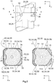
- FIGS. 2a) to 2c show the engine-transmission connection assembly 10 in the assembled state, with the crimping portions 36 not yet bent.
Landscapes
- Engineering & Computer Science (AREA)
- Power Engineering (AREA)
- Mechanical Engineering (AREA)
- General Engineering & Computer Science (AREA)
- Chemical & Material Sciences (AREA)
- Combustion & Propulsion (AREA)
- Transportation (AREA)
- Connection Of Motors, Electrical Generators, Mechanical Devices, And The Like (AREA)
- Motor Or Generator Frames (AREA)
- Motor Or Generator Current Collectors (AREA)
- Arrangement Or Mounting Of Propulsion Units For Vehicles (AREA)
Abstract
Description
- Die vorliegende Erfindung betrifft eine Motor-Getriebe-Verbindungsanordnung, insbesondere zur Verwendung in Fahrzeugen.
- Motor-Getriebe-Verbindungsanordnungen fassen einen Antriebsmotor, beispielsweise einen Elektromotor, und ein Getriebe zu einer Baueinheit zusammen. Die sich hieraus ergebende Baueinheit kann von einem Hersteller vormontiert werden, wodurch der Einbau in eine Vorrichtung, in welche die Baueinheit eingesetzt werden soll, vereinfacht werden kann. Eine besondere Ausgestaltung derartiger Vorrichtungen, wo Motor-Getriebe-Verbindungsanordnungen häufig verwendet werden, stellen Fahrzeuge dar. Im Zuge der Erhöhung des Komforts in Fahrzeugen werden immer mehr Bewegungen zwischen zwei Fahrzeugteilen, die in der Vergangenheit manuell von den Fahrzeuginsassen bewerkstelligt worden, von Motoren, insbesondere von Elektromotoren, ausgeführt. Wurden in älteren Fahrzeugen die Fensterscheiben und Schiebedächer durch Drehen einer Kurbel manuell geöffnet und geschlossen, werden hierzu heutzutage nahezu ausnahmslos elektromotorische Fensterheber eingesetzt. Mehr und mehr setzen sich elektrisch verstellbare Heckklappen durch, mit welchen die Heckklappen per Knopfdruck automatisch öffnen und schließen lassen. Weiterhin nimmt die Anzahl von Assistenz- und Sicherheitssystemen immer weiter zu, so dass der ohnehin schon begrenzte Bauraum im Fahrzeug immer knapper wird. Die Problematik des begrenzten Bauraums wird mit der fortschreitenden Elektrifizierung der Fahrzeuge weiter zunehmen, da die Akkus zum Speichern von elektrischer Energie eine vergleichsweise geringe Energiedichte aufweisen und daher viel Platz benötigen.
- Bei der Verwendung von Elektromotoren umfasst die Motor-Getriebe-Verbindungsanordnung einen Motortopf zum Aufnehmen eines Elektromotors, einen Bürstenhalter zum Halten von Bürsten des Elektromotors, und ein Getriebegehäuse zum Aufnehmen eines Getriebes. Diese drei Komponenten müssen bei der Montage relativ zueinander ausgerichtet und miteinander verbunden werden. Üblicherweise wird der Bürstenhalter innerhalb des Motortopfes zentriert und das Getriebegehäuse über eine flanschartige Verbindung mit dem Motortopf verbunden. Die Verbindung des Getriebegehäuses mit dem Motortopf erfolgt über Schrauben, die durch Öffnungen, welche auf radial nach außen überstehenden Abschnitten des Motortopfes und des Getriebegehäuses angeordnet sind, durchgeführt werden. Aufgrund dieser nach außen überstehenden Abschnitte muss ein gewisser Bauraum freigehalten werden, welcher insbesondere in Fahrzeugen aus den eingangs genannten Gründen knapp ist.
- Bei einer nicht ausreichend genauen Ausrichtung des Bürstenhalters und des Getriebegehäuses in Bezug auf den Motortopf tritt eine erhöhte Geräuschentwicklung im Betrieb einer Antriebsvorrichtung auf, welche eine derartige Motor-Getriebe-Verbindungsanordnung verwendet.
- Aufgabe einer Ausführungsform der vorliegenden Erfindung ist es daher, eine Motor-Getriebe-Verbindungsanordnung zu schaffen, mit welcher Bauraum eingespart werden kann und welche einfach herzustellen und zu montieren ist. Zudem soll die Motor-Getriebe-Verbindungsanordnung eine möglichst genaue Ausrichtung des Motortopfs, des Bürstenhalters und des Getriebegehäuses zueinander ermöglichen.
- Diese Aufgabe wird mit den in den Ansprüchen 1, 5, 6 oder 7 angegebenen Merkmalen gelöst. Vorteilhafte Ausführungsformen sind Gegenstand der Unteransprüche.
- Eine Ausführungsform der Erfindung betrifft eine Motor-Getriebe-Verbindungsanordnung, insbesondere zur Verwendung in Fahrzeugen, umfassend einen Motortopf zum Aufnehmen eines Elektromotors, einen Bürstenhalter zum Halten von Bürsten des Elektromotors, und ein Getriebegehäuse zum Aufnehmen eines Getriebes, wobei der Motortopf, der Bürstenhalter und das Getriebegehäuse zum Verbinden ineinander einsteckbar sind. Der Motortopf weist eine Anzahl von Zentrierflächen auf, mit welchen der Motortopf sowohl mit dem Bürstenhalter als auch mit dem Getriebegehäuse in Kontakt tritt, wenn der Motortopf, der Bürstenhalter und das Getriebegehäuse ineinander eingesteckt sind, wodurch der Bürstenhalter und das Getriebegehäuse konzentrisch zum Motortopf ausgerichtet werden.
- Die Anzahl der Zentrierflächen kann prinzipiell frei gewählt werden. Allerdings ist zu beachten, dass in jede der drei Raumachsen aufgrund von Fertigungstoleranzen nur jeweils ein Paar von Kontaktflächen und Gegenflächen pro Raumachse wirksam sein kann. Zudem ist eine statische Überbestimmung zu vermeiden, so dass zwischen zwei Kontaktflächenpaaren, die an sich miteinander in Kontakt treten könnten, absichtlich ein Spalt vorgesehen wird. Hierdurch können Formänderungen infolge von Temperaturschwankungen ausgeglichen werden, ohne dass Spannungen in die betreffenden Bauteile eingeleitet werden.
- Die Zentrierung des Bürstenhalters und des Getriebegehäuses in Bezug auf den Motortopf wird ausschließlich über die Zentrierflächen vorgenommen, die keine Begrenzung der Bewegbarkeit entlang der Längsachse der Motor-Getriebe-Verbindungsanordnung bewirken, sondern die Bewegbarkeit des Bürstenhalters und des Getriebegehäuses senkrecht zur Längsachse begrenzen. Dadurch, dass die Zentrierung ausschließlich über die Zentrierflächen vorgenommen wird, wird ein Aufsummieren der Fertigungstoleranzen vermieden. Bei der eingangs beschriebenen aus dem Stand der Technik bekannten Motor-Getriebe-Verbindungsanordnung werden der Bürstenhalter und das Getriebegehäuse jeweils separat gegenüber dem Motortopf zentriert, so dass sich hier die Toleranzen addieren.
- Aufgrund der vorschlagsgemäßen Zentrierflächen können der Bürstenhalter und das Getriebegehäuse auf einfache Weise sehr genau konzentrisch zum Motortopf angeordnet werden. Geräuschentwicklungen, welche durch eine unzureichende konzentrische Anordnung des Motortopfs, des Bürstenhalters und des Getriebegehäuses zueinander hervorgerufen werden, werden hierdurch vermieden, so dass die Antriebsvorrichtung, welche Gebrauch von der vorschlagsgemäßen Motor-Getriebe-Verbindungsanordnung macht, sehr leise betrieben werden kann.
- Der Motortopf dient in dieser Ausführungsform als eine Aufnahme, in welche der Bürstenhalter und das Getriebegehäuse eingesteckt werden. Die Zentrierflächen verlaufen innerhalb des Motortopfes, so dass der Bürstenhalter und das Getriebegehäuse im eingesteckten Zustand mehr oder weniger weit in den Motortopf hineinragen, wobei der Bürstenhalter im eingesteckten Zustand auch komplett vom Motortopf umgeben sein kann. Hierdurch kann die Motor-Getriebe-Verbindungsanordnung kürzer gebaut werden, wodurch weiterer Bauraum in axialer Richtung eingespart werden kann. Aufgrund der Möglichkeit, dem Motortopf kürzer zu bauen, muss er auch nicht so weit tiefgezogen werden, was aus fertigungstechnischer Sicht eine Vereinfachung darstellt.
- Die Modifikationen, die am Bürstenhalter gegenüber bekannten Varianten vorgenommen werden müssen, sind signifikant klein. Der Bürstenhalter muss nur so angepasst werden, dass die Kontaktflächen des Motortopfes tatsächlich auch einen Kontakt mit dem Bürstenhalter herstellen können. Der Aufwand zur Herstellung des im Spritzgussverfahren benötigten Werkzeugs unterscheidet sich nicht zu demjenigen, welches bislang verwendet wird. Der Unterschied liegt lediglich in der Kontur der Kavität. Selbiges gilt auch für das Getriebegehäuse. Der prinzipielle Aufbau des Bürstenhalters und des Getriebegehäuses muss nicht geändert werden. Die Bürstenhalter und das Getriebegehäuse können im Spritzgussverfahren hergestellt werden, so dass sich große Stückzahlen zu relativ geringen Kosten herstellen lassen.
- Eine weitere Ausführungsform ist dadurch gekennzeichnet, dass der Motortopf erste Kontaktflächen, mit welchen der Motortopf mit dem Bürstenhalter in Kontakt tritt, und/oder zweite Kontaktflächen aufweist, mit welchen der Motortopf mit dem Getriebegehäuse in Kontakt tritt, wenn der Motortopf, der Bürstenhalter und das Getriebegehäuse ineinander eingesteckt sind. Die ersten und die zweiten Kontaktflächen können dabei so ausgestaltet sein, dass sie bezogen auf die Längsachse der Motor-Getriebe-Verbindungsanordnung als Anschlagsflächen wirken und die Bewegbarkeit der Bauteile relativ zueinander entlang der Längsachse begrenzen. Die ersten und/oder zweiten Kontaktflächen haben keine konzentrisch ausrichtende Wirkung des Bürstenhalters und des Getriebegehäuses in Bezug auf den Motortopf. Es bietet sich an, erste und zweite Gegenflächen im Getriebegehäuse vorzusehen, mit welchen die ersten und/oder zweiten Kontaktflächen in Kontakt treten, wenn der Motortopf, der Bürstenhalter und das Getriebegehäuse ineinander eingesteckt sind.
- Nach Maßgabe einer weiteren Ausführungsform weist der Bürstenhalter dritte Kontaktflächen auf, mit welchen der Bürstenhalter mit dem Getriebegehäuse in Kontakt tritt, wenn der Motortopf, der Bürstenhalter und das Getriebegehäuse ineinander eingesteckt sind. Es bietet sich dabei an, die dritten Kontaktflächen mit Quetschrippen zu versehen, welche zum Spielausgleich der Motor-Getriebe-Verbindungsanordnung entlang der Längsachse dienen. Darüber hinaus bietet es sich an, dritte Gegenflächen im Getriebegehäuse vorzusehen, mit welchen die dritten Kontaktflächen in Kontakt treten, wenn der Motortopf, der Bürstenhalter und das Getriebegehäuse ineinander eingesteckt sind.
- In dieser Ausführungsform wird das Getriebegehäuse gleichzeitig dazu verwendet, die Beweglichkeit des Bürstenhalters entlang der Längsachse der Motor-Getriebe-Verbindungsanordnung zu beschränken, so dass keine weiteren Maßnahmen hierzu getroffen werden müssen. Die Gestaltung und die Montage werden hierdurch vereinfacht.
- Mit den vorschlagsgemäßen Zentrierflächen werden der Bürstenhalter und das Getriebegehäuse in Bezug auf den Motortopf eindeutig zentriert und konzentrisch zum Motortopf angeordnet, so dass keine weiteren Maßnahmen, beispielsweise die Verwendung von Positionierungsstiften oder dergleichen mehr notwendig ist. Weiterhin ist es insbesondere dann, wenn die Motor-Getriebe-Verbindungsanordnung die dritten Kontaktflächen aufweist, nicht mehr notwendig, gesonderte Befestigungsmaßnahmen zum Befestigen des Bürstenhalters innerhalb der Motor-Getriebe-Verbindungsanordnung vorzunehmen. Somit genügt es, den Motortopf und das Getriebegehäuse miteinander zu verbinden, da der Bürstenhalter bezogen auf die Längsachse einerseits am Motortopf und andererseits am Getriebegehäuse anliegt.
- In einer weitergebildeten Ausführungsform können der Motortopf und/oder das Getriebegehäuse Crimpabschnitte zum Verbinden des Getriebegehäuses mit dem Motortopfes aufweisen.
- Wie eingangs erwähnt, wird dies bei bekannten Motor-Getriebe-Verbindungsanordnung mittels einer Verschraubung unter Verwendung einer flanschartigen Verbindung umgesetzt. Die vorschlagsgemäße Motor-Getriebe-Verbindungsanordnung ermöglicht die Verwendung von Crimpabschnitten, die zum Verbinden des Motortopfes und des Getriebegehäuses mittels eines geeigneten Werkzeugs verformt werden. Hierdurch ist die flanschartige Verbindung nicht mehr notwendig, weshalb die Erstreckung der Motor-Getriebe-Verbindungsanordnung in radialer Richtung verringert und Bauraum eingespart werden kann.
- In einer alternativen Ausführungsform weist die Motor-Getriebe-Verbindungsanordnung Zentrierflächen auf, mit welchen das Getriebegehäuse sowohl mit dem Bürstenhalter als auch mit dem Motortopf in Kontakt tritt, wenn der Motortopf, der Bürstenhalter und das Getriebegehäuse ineinander eingesteckt sind, wodurch der Bürstenhalter und der Motortopf konzentrisch zum Getriebegehäuse ausgerichtet werden. Die oben genannten Vorteile gelten auch für diese alternative Ausführungsform.
- Eine Umsetzung der Erfindung betrifft ein Schiebedach in einem Fahrzeug, umfassend eine Motor-Getriebe-Verbindungsanordnung nach einem der vorherigen Ausführungsformen. Zudem betrifft eine Ausführung der Erfindung die Verwendung einer Motor-Getriebe-Verbindungsanordnung nach einem der vorherigen Ausführungsformen für Hilfsantriebe in Fahrzeugen, insbesondere in Kraftfahrzeugen. Unter Hilfsantrieben sind Antriebe zu verstehen, mit denen ein Fahrzeugteil relativ zu einem anderen Fahrzeugteil bewegt wird, beispielsweise bei Fensterhebern, Heckklappen und Sitzen. Hilfsantriebe sind aber nicht geeignet, das Fahrzeug selbst zu bewegen.
- Eine Ausgestaltung der Erfindung betrifft ein Fahrzeug, insbesondere Kraftfahrzeug, umfassend Motor-Getriebe-Verbindungsanordnung nach einem der vorherigen Ausführungsformen. Die Vorteile und technischen Effekte, die sich mit einem derartigen Schiebedach, der Verwendung der Motor-Getriebe-Verbindungsanordnung und einem derartigen Fahrzeug realisieren lassen, entsprechen denjenigen, welche für die verschiedenen Ausführungsformen der Motor-Getriebe-Verbindungsanordnung beschrieben worden sind. Dadurch, dass die Zentrierung ausschließlich über die Zentrierflächen vorgenommen wird, wird ein Aufsummieren der Toleranzen vermieden. Weiterhin ist ein Vercrimpen zum Befestigen des Getriebegehäuses am Motortopf möglich, wohingegen im Stand der Technik eine Verschraubung notwendig ist. Hierdurch wird die Logistik vereinfacht, da die Vercrimpabschnitte direkt am Motortopf und/oder am Getriebegehäuse angeformt sind und daher keine separaten Verbindungselemente vorgehalten werden müssen. Für den Antrieb eines Schiebedachs steht insbesondere dann sehr wenig Bauraum zur Verfügung, wenn das Schiebedach als Panoramadach ausgestaltet ist. Insbesondere in diesem Fall kommt der reduzierte Bauraum der vorschlagsgemäßen Motor-Getriebe-Verbindungsanordnung besonders stark zur Geltung. Weiterhin lässt sich aufgrund der Möglichkeit, den Bürstenhalter und das Getriebegehäuse sehr präzise konzentrisch zum Motortopf anzuordnen, ein sehr geräuscharmer Betrieb der Antriebsvorrichtung realisieren, welche die vorschlagsgemäße Motor-Getriebe-Verbindungsanordnung verwendet.
- Beispielhafte Ausführungsformen der Erfindung werden im Folgenden unter Bezugnahme auf die beigefügten Zeichnungen näher erläutert. Es zeigen
- Figur 1a)
- eine erste perspektivische Explosionsdarstellung eines Ausführungsbeispiels einer vorschlagsgemäßen Motor-Getriebe-Verbindungsanordnung,
- Figur 1b)
- eine zweite perspektivische Explosionsdarstellung der in
Figur 1a ) gezeigten Motor-Getriebe-Verbindungsanordnung, - Figur 2a)
- eine Seitenansicht der in
Figur 1a ) dargestellten Motor-Getriebe-Verbindungsanordnung im zusammengebauten Zustand, - Figur 2b)
- eine Schnittdarstellung entlang der in
Figur 2a ) definierten Schnittebene A-A, und - Figur 2c)
- eine Schnittdarstellung entlang der in
Figur 2a ) definierten Schnittebene B-B. - In den
Figuren 1a) bis 2c ) ist ein Ausführungsbeispiel einer erfindungsgemäßen Motor-Getriebe-Verbindungsanordnung 10 dargestellt. Die Motor-Getriebe-Verbindungsanordnung 10 umfasst einen Motortopf 12 zum Aufnehmen eines nicht dargestellten Elektromotors, einen Bürstenhalter 14, mit welchem nicht dargestellte Bürsten für den Elektromotor gehalten werden, und ein Getriebegehäuse 16 zum Aufnehmen eines ebenfalls nicht dargestellten Getriebes. - Der Motortopf 12 umfasst erste Kontaktflächen 18, mit denen der Motortopf 12 mit dem Bürstenhalter 14 in Kontakt tritt, wenn der Bürstenhalter 14 in den Motortopf 12 eingesteckt ist. Weiterhin weist der Motortopf 12 zweite Kontaktflächen 20 auf, mit denen der Motortopf 12 mit dem Getriebegehäuse 16 in Kontakt tritt, wenn das Getriebegehäuse 16 in den Motortopf 12 eingesteckt ist.
- Zudem weist der Bürstenhalter 14 dritte Kontaktflächen 24 auf, mit denen der Bürstenhalter 14 mit dem Getriebegehäuse 16 in Kontakt tritt, wenn der Bürstenhalter 14 und das Getriebegehäuse 16 in den Motortopf 12 eingesteckt sind. Auf den dritten Kontaktflächen 24 sind Quetschrippen 32 angeordnet, auf die später noch genauer eingegangen wird.
- Darüber hinaus umfasst der Motortopf 12 Zentrierflächen 50, welche in x-Richtung wirken, und Zentrierflächen 52 auf, die in y-Richtung wirken, mit denen der Motortopf 12 sowohl mit dem Bürstenhalter 14 als auch mit dem Getriebegehäuse 16 in Kontakt tritt, wenn der Bürstenhalter 14 und das Getriebegehäuse 16 in den Motortopf 12 eingesteckt sind.
- Der Bürstenhalter 14 und das Getriebegehäuse 16 weisen erste Gegenflächen 26, zweite Gegenflächen 28 und dritte Gegenflächen 30 auf, mit denen sie mit der oder den ersten, zweiten bzw. dritten Kontaktflächen 18, 20, 24 in Kontakt treten, wenn der Bürstenhalter 14 und das Getriebegehäuse 16 in den Motortopf 12 eingesteckt sind.
- Zudem weisen der Bürstenhalter 14 und das Getriebegehäuse 16 Zentriergegenflächen 54, die bezogen auf das in den Figuren angegebene Koordinatensystem in x-Richtung wirken, und Zentriergegenflächen 56 auf, die in y-Richtung wirken. Folglich verlaufen die Zentriergegenflächen 54 parallel zu einer Längsachse L und liegen in der y-z-Ebene und bewirken bei Kontakt mit den Zentrierflächen 50 eine Zentrierung in die x-Richtung. Entsprechend verlaufen die Zentrierflächen 56 parallel zur Längsachse L und liegen in der x-z- Ebene. Sie bewirken bei Kontakt mit den Zentrierflächen 52 eine Zentrierung in y-Richtung bezogen auf das Koordinatensystem.
- Im dargestellten Ausführungsbeispiel sind die Zentriergegenflächen 54 in x-Richtung als Erhöhungen 58 ausgestaltet oder auf Erhöhungen 58 angeordnet. Die Zentriergegenflächen 54 treten mit den Zentrierflächen 50 und die Zentriergegenflächen 56 mit den Zentrierflächen 52 in Kontakt, wenn der Bürstenhalter 14 und das Getriebegehäuse 16 in den Motortopf 12 eingesteckt sind.
- Bei Betrachtung der
Figuren 1a ) und1b ) erkennt man, dass die ersten, zweiten und dritten Kontaktflächen 18, 20, 24 in einer senkrecht zur Längsachse L der Motor-Getriebe-Verbindungsanordnung 10 verlaufenden Ebene liegen. Bezogen auf das Koordinatensystem verlaufen sie in einer x-y-Ebene, wobei die Längsachse L parallel zur z-Achse des Koordinatensystems verläuft. - Auch die ersten, zweiten und dritten Gegenflächen 26, 28, 30 liegen in der senkrecht zur Längsachse L verlaufenden x-y-Ebene. Folglich wirken die ersten, zweiten und dritten Kontaktflächen 18, 20, 24 als Anschläge, welche die Bewegbarkeit des Motortopfes 12, des Bürstenhalters 14 und des Getriebegehäuses 16 relativ zueinander entlang der Längsachse L bzw. in z-Richtung begrenzen.
- Darüber hinaus weist der Motortopf 12 insgesamt sechs Crimpabschnitte 36 auf, mit denen das Getriebegehäuse 16 am Motortopf 12 befestigt werden kann und wodurch der Bürstenhalter 14 zwischen dem Motortopf 12 und dem Getriebegehäuse 16 verspannt wird.
- Zur Montage der Motor-Getriebe-Verbindungsanordnung 10 wird zunächst der Bürstenhalter 14 in den Motortopf 12 eingebracht, bis dass die ersten Gegenflächen 26 des Bürstenhalters 14 mit den ersten Kontaktflächen 18 des Motortopfes 12 in Kontakt treten. Dabei treten die Zentriergegenflächen 54 in x-Richtung und die Zentriergegenflächen 56 in y-Richtung des Bürstenhalters 14 in Kontakt mit den Zentrierflächen 50 in x-Richtung und den Zentrierflächen 52 in y-Richtung des Motortopfes 12, wodurch der Bürstenhalter 14 bezogen auf die Längsachse L konzentrisch zum Motortopf 12 ausgerichtet wird.
- Anschließend wird das Getriebegehäuse 16 in den Motortopf 12 eingebracht, bis dass die zweiten Gegenflächen 28 mit den zweiten Kontaktflächen 20 des Motortopfes 12 und die dritten Gegenflächen 30 mit den dritten Kontaktflächen 24 des Bürstenhalters 14 in Kontakt treten. Hierbei treten die Zentriergegenflächen 54, 56 in x- und in y-Richtung des Getriebegehäuses 16 mit den Zentrierflächen 50, 52 in x- und in y-Richtung des Motortopfes 12 in Kontakt, so dass auch das Getriebegehäuse 16 bezogen auf die Längsachse L konzentrisch zum Motortopf 12 ausgerichtet wird. Folglich wirken die Zentrierflächen 50, 52 in x- und in y-Richtung und die Zentriergegenflächen 54, 56 in x- und in y-Richtung auch in Bezug auf das Getriebegehäuse 16 zentrierend.
- Insbesondere aus
Figur 1a ) ist zu entnehmen, dass der Motortopf 12 insgesamt drei erste Kontaktflächen 18 aufweist, die in einer Ausnehmung der im Querschnitt in etwa rechteckig verlaufenden Wandung des Motortopfes 12 angeordnet sind. Entsprechend weist der Bürstenhalter 14 drei erste Gegenflächen 26 auf, die auf Vorsprüngen des Bürstenhalters 14 angeordnet sind, welche in die Ausnehmungen des Motortopfes 12 eingreifen können. Auch das Getriebegehäuse 16 weist drei dritte Gegenflächen 30 auf, die in die Ausnehmungen des Motortopfes eingreifen können. Die Ausnehmungen sind so angeordnet, dass der Bürstenhalter 14 und das Getriebegehäuse 16 nur in einer Drehstellung in den Motortopf 12 eingebracht werden können. Um das Getriebegehäuse 16 am Motortopf 12 zu befestigen, werden die Crimpabschnitte 36 radial einwärts zur Längsachse L hin verbogen, so dass ein Formschluss zwischen dem Getriebegehäuse 16 und dem Motortopf 12 hergestellt wird. Die Crimpabschnitte 36 weisen Crimpflächen 38 (sieheFigur 1b )) auf, die in etwa in der x-y-Ebene liegen und mit Crimpgegenflächen 40 des Getriebegehäuses 16 (sieheFigur 1a )) in Kontakt treten. Die Crimpgegenflächen 40 verlaufen in etwa in der x-y-Ebene, ist aber etwas gegenüber der x-y-Ebene geneigt. Beim Vercrimpen bzw. beim Verbiegen der Crimpabschnitte 36 reiben die Crimpflächen 38 auf den Crimpgegenflächen 40, so dass zumindest anteilig auch ein Reibschluss bereitgestellt wird. - Da der Bürstenhalter 14 einerseits mit seinen ersten Gegenflächen 26 an den ersten Kontaktflächen 18 des Motortopfes 12 und andererseits mit seinen dritten Kontaktflächen 24 an den dritten Gegenflächen 30 des Getriebegehäuses 16 anliegt, ist seine Position innerhalb der Motor-Getriebe-Verbindungsanordnung 10 eindeutig festgelegt, sobald die Crimpabschnitte 36 verbogen worden sind. Aufgrund der Neigung der Crimpabschnitte 40 gegenüber der x-y-Ebene erfolgt eine finale Positionierung des Getriebegehäuses 16 und des Bürstenhalters 14 bezogen auf die Längsachse L. Die Quetschrippen 32 sind so ausgestaltet, dass sie beim Verbiegen der Crimpabschnitte 40 gestaucht werden, wodurch das Spiel der Motor-Getriebe-Verbindungsanordnung 10 entlang der Längsrichtung ausgeglichen wird.
- Die
Figuren 2a) bis 2c ) zeigen die Motor-Getriebe-Verbindungsanordnung 10 im zusammengebauten Zustand, wobei die Crimpabschnitte 36 noch nicht verbogen worden sind. -
- 10
- Motor-Getriebe-Verbindungsanordnung
- 12
- Motortopf
- 14
- Bürstenhalter
- 16
- Getriebegehäuse
- 18
- erste Kontaktflächen
- 20
- zweite Kontaktflächen
- 24
- dritte Kontaktflächen
- 26
- erste Gegenflächen
- 28
- zweite Gegenflächen
- 30
- dritte Gegenflächen
- 32
- Quetschrippen
- 36
- Crimpabschnitt
- 38
- Crimpflächen
- 40
- Crimpgegenflächen
- 50
- Zentrierflächen in x-Richtung
- 52
- Zentrierflächen in y-Richtung
- 54
- Zentriergegenflächen in x-Richtung
- 56
- Zentriergegenflächen in y-Richtung
- 58
- Erhöhungen
- L
- Längsachse
Claims (7)
- Motor-Getriebe-Verbindungsanordnung, insbesondere zur Verwendung in Fahrzeugen, umfassend- einen Motortopf (12) zum Aufnehmen eines Elektromotors,- einen Bürstenhalter (14) zum Halten von Bürsten des Elektromotors, und- ein Getriebegehäuse (16) zum Aufnehmen eines Getriebes,- wobei der Motortopf (12), der Bürstenhalter (14) und das Getriebegehäuse (16) zum Verbinden ineinander einsteckbar sind, und- der Motortopf (12) eine Anzahl von Zentrierflächen (50,52) aufweist, mit welchen der Motortopf (12) sowohl mit dem Bürstenhalter (14) als auch mit dem Getriebegehäuse (16) in Kontakt tritt, wenn der Motortopf (12), der Bürstenhalter (14) und das Getriebegehäuse (16) ineinander eingesteckt sind, wodurch der Bürstenhalter (14) und das Getriebegehäuse (16) konzentrisch zum Motortopf (12) ausgerichtet werden.
- Motor-Getriebe-Verbindungsanordnung nach Anspruch 1,
dadurch gekennzeichnet, dass der Motortopf (12)- erste Kontaktflächen (18), mit welchen der Motortopf (12) mit dem Bürstenhalter (14) in Kontakt tritt, und/oder- zweite Kontaktflächen (20) aufweist, mit welchen der Motortopf (12) mit dem Getriebegehäuse (16) in Kontakt tritt, wenn der Motortopf (12), der Bürstenhalter (14) und das Getriebegehäuse (16) ineinander eingesteckt sind. - Motor-Getriebe-Verbindungsanordnung nach einem der Ansprüche 1 oder 2,
dadurch gekennzeichnet, dass der Bürstenhalter (14) dritte Kontaktflächen (24) aufweist, mit welchen der Bürstenhalter (14) mit dem Getriebegehäuse (16) in Kontakt tritt, wenn der Motortopf (12), der Bürstenhalter (14) und das Getriebegehäuse (16) ineinander eingesteckt sind. - Motor-Getriebe-Verbindungsanordnung nach einem der vorherigen Ansprüche,
dadurch gekennzeichnet, dass der Motortopf (12) und/oder das Getriebegehäuse (16) Crimpabschnitte (36) zum Verbinden des Getriebegehäuses (16) mit dem Motortopf (12) aufweisen. - Schiebedach in Fahrzeugen, umfassend Motor-Getriebe-Verbindungsanordnung (10) nach einem der vorherigen Ansprüche.
- Verwendung einer Motor-Getriebe-Verbindungsanordnung (10) nach einem der Ansprüche 1 bis 3 in Hilfsantrieben in Fahrzeugen, insbesondere in Kraftfahrzeugen.
- Fahrzeug, insbesondere Kraftfahrzeug, umfassend Motor-Getriebe-Verbindungsanordnung (10) nach einem der Ansprüche 1 bis 3.
Priority Applications (5)
| Application Number | Priority Date | Filing Date | Title |
|---|---|---|---|
| EP17172633.4A EP3407471B1 (de) | 2017-05-24 | 2017-05-24 | Motor-getriebe-verbindungsanordnung, insbesondere zur verwendung in fahrzeugen |
| ES17172633T ES2894253T3 (es) | 2017-05-24 | 2017-05-24 | Disposición de conexión de motor-engranaje, en particular, para su uso en vehículos |
| CN201810503902.5A CN108928232B (zh) | 2017-05-24 | 2018-05-23 | 一种发动机-变速器连接组件 |
| KR1020180058594A KR102021512B1 (ko) | 2017-05-24 | 2018-05-23 | 차량용 모터 변속기 연결장치 |
| US15/987,709 US10873236B2 (en) | 2017-05-24 | 2018-05-23 | Motor transmission connection arrangement, in particular for use in vehicles |
Applications Claiming Priority (1)
| Application Number | Priority Date | Filing Date | Title |
|---|---|---|---|
| EP17172633.4A EP3407471B1 (de) | 2017-05-24 | 2017-05-24 | Motor-getriebe-verbindungsanordnung, insbesondere zur verwendung in fahrzeugen |
Publications (2)
| Publication Number | Publication Date |
|---|---|
| EP3407471A1 true EP3407471A1 (de) | 2018-11-28 |
| EP3407471B1 EP3407471B1 (de) | 2021-07-21 |
Family
ID=58772501
Family Applications (1)
| Application Number | Title | Priority Date | Filing Date |
|---|---|---|---|
| EP17172633.4A Active EP3407471B1 (de) | 2017-05-24 | 2017-05-24 | Motor-getriebe-verbindungsanordnung, insbesondere zur verwendung in fahrzeugen |
Country Status (5)
| Country | Link |
|---|---|
| US (1) | US10873236B2 (de) |
| EP (1) | EP3407471B1 (de) |
| KR (1) | KR102021512B1 (de) |
| CN (1) | CN108928232B (de) |
| ES (1) | ES2894253T3 (de) |
Citations (3)
| Publication number | Priority date | Publication date | Assignee | Title |
|---|---|---|---|---|
| DE10138749A1 (de) * | 2000-07-31 | 2002-03-07 | Valeo Electrical Sys Inc | Integrale Bürstenhalterdichtungsscheibe |
| DE102014212135A1 (de) * | 2014-06-25 | 2015-12-31 | Robert Bosch Gmbh | Getriebe-Antriebseinrichtung und Verfahren zur Montage einer Getriebe-Antriebseinrichtung |
| US20160134073A1 (en) * | 2013-07-11 | 2016-05-12 | Mitsuba Corporation | Electric motor |
Family Cites Families (10)
| Publication number | Priority date | Publication date | Assignee | Title |
|---|---|---|---|---|
| JP3757240B2 (ja) * | 1997-08-28 | 2006-03-22 | 自動車電機工業株式会社 | 小型モータ |
| EP1101967B1 (de) * | 1998-08-03 | 2015-03-18 | Asmo Co. Ltd. | Kupplung und mit dieser kupplung versehenen antriebsvorrichtung |
| US6288464B1 (en) * | 1999-07-13 | 2001-09-11 | Asmo Co., Ltd. | Motor having worm gear mechanism |
| JP4159263B2 (ja) * | 2001-04-19 | 2008-10-01 | 株式会社ミツバ | モータ |
| CN100519300C (zh) * | 2003-02-20 | 2009-07-29 | 日本精工株式会社 | 电动动力转向装置 |
| DE102005008073B4 (de) * | 2004-02-24 | 2014-01-16 | Asmo Co., Ltd. | Motor mit einem Steuerschaltungsteil, ein Steuerschaltungsteil und Verfahren zur Herstellung des Motors |
| JP5006713B2 (ja) | 2007-06-28 | 2012-08-22 | 株式会社ミツバ | ブラシ付き電動モータ |
| DE102008043173A1 (de) * | 2008-07-04 | 2010-01-07 | Robert Bosch Gmbh | Getriebe-Antriebseinheit mit einer Selbsthemmvorrichtung |
| US9525322B2 (en) * | 2011-11-22 | 2016-12-20 | Mitsuba Corporation | Wiper motor |
| JP6095510B2 (ja) * | 2013-07-11 | 2017-03-15 | 株式会社ミツバ | ワイパモータ |
-
2017
- 2017-05-24 ES ES17172633T patent/ES2894253T3/es active Active
- 2017-05-24 EP EP17172633.4A patent/EP3407471B1/de active Active
-
2018
- 2018-05-23 CN CN201810503902.5A patent/CN108928232B/zh not_active Expired - Fee Related
- 2018-05-23 KR KR1020180058594A patent/KR102021512B1/ko not_active Expired - Fee Related
- 2018-05-23 US US15/987,709 patent/US10873236B2/en not_active Expired - Fee Related
Patent Citations (3)
| Publication number | Priority date | Publication date | Assignee | Title |
|---|---|---|---|---|
| DE10138749A1 (de) * | 2000-07-31 | 2002-03-07 | Valeo Electrical Sys Inc | Integrale Bürstenhalterdichtungsscheibe |
| US20160134073A1 (en) * | 2013-07-11 | 2016-05-12 | Mitsuba Corporation | Electric motor |
| DE102014212135A1 (de) * | 2014-06-25 | 2015-12-31 | Robert Bosch Gmbh | Getriebe-Antriebseinrichtung und Verfahren zur Montage einer Getriebe-Antriebseinrichtung |
Also Published As
| Publication number | Publication date |
|---|---|
| KR20180128861A (ko) | 2018-12-04 |
| ES2894253T3 (es) | 2022-02-14 |
| US20180342924A1 (en) | 2018-11-29 |
| CN108928232B (zh) | 2022-04-15 |
| US10873236B2 (en) | 2020-12-22 |
| EP3407471B1 (de) | 2021-07-21 |
| KR102021512B1 (ko) | 2019-09-16 |
| CN108928232A (zh) | 2018-12-04 |
Similar Documents
| Publication | Publication Date | Title |
|---|---|---|
| EP2780200B1 (de) | Gehäuse und bausatz für eine steuerungsvorrichtung | |
| DE102011053453B4 (de) | Montage- und dämpfungssystem für einen kompressor | |
| EP2992594B1 (de) | Gehäuseanordnung mit einem gehäusebauteil für eine elektrische maschine und einer elektrischen leiterplatte | |
| DE102014212135A1 (de) | Getriebe-Antriebseinrichtung und Verfahren zur Montage einer Getriebe-Antriebseinrichtung | |
| DE112010002847T5 (de) | Elektrischer Getriebemotor, insbesondere für Fensterheber und Scheibenwischerfür Automobile und dergleichen | |
| EP4029132B1 (de) | Elektrische antriebseinrichtung und antriebsanordnung | |
| DE69706844T2 (de) | Kollektorgehäuse-und motorgetriebeanschlusseinheit | |
| DE102016115045B4 (de) | Gehäuse für eine Motor-Getriebeeinheit und Herstellungsverfahren | |
| DE102018202624A1 (de) | Rotor sowie Verfahren zum Herstellen eines Rotors | |
| DE102022104364B3 (de) | Halter für elektrische steckverbindung und elektrisches antriebssystem | |
| EP3407471B1 (de) | Motor-getriebe-verbindungsanordnung, insbesondere zur verwendung in fahrzeugen | |
| EP2745025A1 (de) | Getriebe-antriebseinrichtung | |
| DE102018218527A1 (de) | Gehäusedeckel für eine elektrische Maschine und Verfahren zum Herstellen eines Gehäusedeckels | |
| EP3406933A1 (de) | Getriebeanordnung für hilfsantrieb sowie motor-getriebe-verbindungsanordnung in einem fahrzeug, insbesondere in einem kraftfahrzeug | |
| EP1619774A1 (de) | Bürstensystem für einen Kraftfahrzeug-Stellantrieb | |
| DE102013202857A1 (de) | Bürstenträger für einen Elektromotor und Getriebe-Antriebseinheit mit einem Bürstenträger | |
| DE102012205481A1 (de) | Elektrische Maschine und Verfahren zur Montage einer elektrischen Maschine | |
| DE102005047978B3 (de) | Antriebsgehäuse für ein bewegbares Fahrzeugteil | |
| EP2840689B1 (de) | Kfz-Aggregat und Verfahren zur Befestigung eines Steckers an einem Kfz-Aggregat | |
| DE102019203422A1 (de) | Adapterelement für eine Getriebe-Antriebseinrichtung, Getriebe-Antriebseinrichtung und Werkzeug zur Herstellung eines Adapterelements | |
| WO2008148629A2 (de) | Elektromaschinensystem | |
| EP3479461A1 (de) | Kombination aus motorgehäuse und steckeranschluss sowie dafür vorgesehenes motorgehäuse | |
| DE102017223379A1 (de) | Bürstenträger-Bauteil für eine elektrische Maschine sowie elektrische Maschine | |
| DE102022107510A1 (de) | Antriebseinheit für kraftfahrzeug-technische Anwendungen | |
| DE102024203409A1 (de) | Steckerbaugruppe |
Legal Events
| Date | Code | Title | Description |
|---|---|---|---|
| PUAI | Public reference made under article 153(3) epc to a published international application that has entered the european phase |
Free format text: ORIGINAL CODE: 0009012 |
|
| STAA | Information on the status of an ep patent application or granted ep patent |
Free format text: STATUS: THE APPLICATION HAS BEEN PUBLISHED |
|
| AK | Designated contracting states |
Kind code of ref document: A1 Designated state(s): AL AT BE BG CH CY CZ DE DK EE ES FI FR GB GR HR HU IE IS IT LI LT LU LV MC MK MT NL NO PL PT RO RS SE SI SK SM TR |
|
| AX | Request for extension of the european patent |
Extension state: BA ME |
|
| STAA | Information on the status of an ep patent application or granted ep patent |
Free format text: STATUS: REQUEST FOR EXAMINATION WAS MADE |
|
| 17P | Request for examination filed |
Effective date: 20190416 |
|
| RBV | Designated contracting states (corrected) |
Designated state(s): AL AT BE BG CH CY CZ DE DK EE ES FI FR GB GR HR HU IE IS IT LI LT LU LV MC MK MT NL NO PL PT RO RS SE SI SK SM TR |
|
| STAA | Information on the status of an ep patent application or granted ep patent |
Free format text: STATUS: EXAMINATION IS IN PROGRESS |
|
| 17Q | First examination report despatched |
Effective date: 20200120 |
|
| GRAP | Despatch of communication of intention to grant a patent |
Free format text: ORIGINAL CODE: EPIDOSNIGR1 |
|
| STAA | Information on the status of an ep patent application or granted ep patent |
Free format text: STATUS: GRANT OF PATENT IS INTENDED |
|
| RIC1 | Information provided on ipc code assigned before grant |
Ipc: H02K 5/14 20060101AFI20210308BHEP Ipc: H02K 7/116 20060101ALI20210308BHEP Ipc: H02K 5/15 20060101ALI20210308BHEP |
|
| INTG | Intention to grant announced |
Effective date: 20210330 |
|
| GRAS | Grant fee paid |
Free format text: ORIGINAL CODE: EPIDOSNIGR3 |
|
| GRAA | (expected) grant |
Free format text: ORIGINAL CODE: 0009210 |
|
| STAA | Information on the status of an ep patent application or granted ep patent |
Free format text: STATUS: THE PATENT HAS BEEN GRANTED |
|
| AK | Designated contracting states |
Kind code of ref document: B1 Designated state(s): AL AT BE BG CH CY CZ DE DK EE ES FI FR GB GR HR HU IE IS IT LI LT LU LV MC MK MT NL NO PL PT RO RS SE SI SK SM TR |
|
| REG | Reference to a national code |
Ref country code: GB Ref legal event code: FG4D Free format text: NOT ENGLISH |
|
| REG | Reference to a national code |
Ref country code: CH Ref legal event code: EP |
|
| REG | Reference to a national code |
Ref country code: DE Ref legal event code: R096 Ref document number: 502017010940 Country of ref document: DE |
|
| REG | Reference to a national code |
Ref country code: AT Ref legal event code: REF Ref document number: 1413512 Country of ref document: AT Kind code of ref document: T Effective date: 20210815 |
|
| REG | Reference to a national code |
Ref country code: IE Ref legal event code: FG4D Free format text: LANGUAGE OF EP DOCUMENT: GERMAN |
|
| REG | Reference to a national code |
Ref country code: LT Ref legal event code: MG9D |
|
| REG | Reference to a national code |
Ref country code: NL Ref legal event code: MP Effective date: 20210721 |
|
| PG25 | Lapsed in a contracting state [announced via postgrant information from national office to epo] |
Ref country code: RS Free format text: LAPSE BECAUSE OF FAILURE TO SUBMIT A TRANSLATION OF THE DESCRIPTION OR TO PAY THE FEE WITHIN THE PRESCRIBED TIME-LIMIT Effective date: 20210721 Ref country code: SE Free format text: LAPSE BECAUSE OF FAILURE TO SUBMIT A TRANSLATION OF THE DESCRIPTION OR TO PAY THE FEE WITHIN THE PRESCRIBED TIME-LIMIT Effective date: 20210721 Ref country code: NO Free format text: LAPSE BECAUSE OF FAILURE TO SUBMIT A TRANSLATION OF THE DESCRIPTION OR TO PAY THE FEE WITHIN THE PRESCRIBED TIME-LIMIT Effective date: 20211021 Ref country code: NL Free format text: LAPSE BECAUSE OF FAILURE TO SUBMIT A TRANSLATION OF THE DESCRIPTION OR TO PAY THE FEE WITHIN THE PRESCRIBED TIME-LIMIT Effective date: 20210721 Ref country code: PT Free format text: LAPSE BECAUSE OF FAILURE TO SUBMIT A TRANSLATION OF THE DESCRIPTION OR TO PAY THE FEE WITHIN THE PRESCRIBED TIME-LIMIT Effective date: 20211122 Ref country code: FI Free format text: LAPSE BECAUSE OF FAILURE TO SUBMIT A TRANSLATION OF THE DESCRIPTION OR TO PAY THE FEE WITHIN THE PRESCRIBED TIME-LIMIT Effective date: 20210721 Ref country code: HR Free format text: LAPSE BECAUSE OF FAILURE TO SUBMIT A TRANSLATION OF THE DESCRIPTION OR TO PAY THE FEE WITHIN THE PRESCRIBED TIME-LIMIT Effective date: 20210721 Ref country code: BG Free format text: LAPSE BECAUSE OF FAILURE TO SUBMIT A TRANSLATION OF THE DESCRIPTION OR TO PAY THE FEE WITHIN THE PRESCRIBED TIME-LIMIT Effective date: 20211021 Ref country code: LT Free format text: LAPSE BECAUSE OF FAILURE TO SUBMIT A TRANSLATION OF THE DESCRIPTION OR TO PAY THE FEE WITHIN THE PRESCRIBED TIME-LIMIT Effective date: 20210721 |
|
| REG | Reference to a national code |
Ref country code: ES Ref legal event code: FG2A Ref document number: 2894253 Country of ref document: ES Kind code of ref document: T3 Effective date: 20220214 |
|
| PG25 | Lapsed in a contracting state [announced via postgrant information from national office to epo] |
Ref country code: PL Free format text: LAPSE BECAUSE OF FAILURE TO SUBMIT A TRANSLATION OF THE DESCRIPTION OR TO PAY THE FEE WITHIN THE PRESCRIBED TIME-LIMIT Effective date: 20210721 Ref country code: LV Free format text: LAPSE BECAUSE OF FAILURE TO SUBMIT A TRANSLATION OF THE DESCRIPTION OR TO PAY THE FEE WITHIN THE PRESCRIBED TIME-LIMIT Effective date: 20210721 Ref country code: GR Free format text: LAPSE BECAUSE OF FAILURE TO SUBMIT A TRANSLATION OF THE DESCRIPTION OR TO PAY THE FEE WITHIN THE PRESCRIBED TIME-LIMIT Effective date: 20211022 |
|
| REG | Reference to a national code |
Ref country code: DE Ref legal event code: R097 Ref document number: 502017010940 Country of ref document: DE |
|
| PG25 | Lapsed in a contracting state [announced via postgrant information from national office to epo] |
Ref country code: DK Free format text: LAPSE BECAUSE OF FAILURE TO SUBMIT A TRANSLATION OF THE DESCRIPTION OR TO PAY THE FEE WITHIN THE PRESCRIBED TIME-LIMIT Effective date: 20210721 |
|
| PLBE | No opposition filed within time limit |
Free format text: ORIGINAL CODE: 0009261 |
|
| STAA | Information on the status of an ep patent application or granted ep patent |
Free format text: STATUS: NO OPPOSITION FILED WITHIN TIME LIMIT |
|
| PG25 | Lapsed in a contracting state [announced via postgrant information from national office to epo] |
Ref country code: SM Free format text: LAPSE BECAUSE OF FAILURE TO SUBMIT A TRANSLATION OF THE DESCRIPTION OR TO PAY THE FEE WITHIN THE PRESCRIBED TIME-LIMIT Effective date: 20210721 Ref country code: SK Free format text: LAPSE BECAUSE OF FAILURE TO SUBMIT A TRANSLATION OF THE DESCRIPTION OR TO PAY THE FEE WITHIN THE PRESCRIBED TIME-LIMIT Effective date: 20210721 Ref country code: RO Free format text: LAPSE BECAUSE OF FAILURE TO SUBMIT A TRANSLATION OF THE DESCRIPTION OR TO PAY THE FEE WITHIN THE PRESCRIBED TIME-LIMIT Effective date: 20210721 Ref country code: EE Free format text: LAPSE BECAUSE OF FAILURE TO SUBMIT A TRANSLATION OF THE DESCRIPTION OR TO PAY THE FEE WITHIN THE PRESCRIBED TIME-LIMIT Effective date: 20210721 Ref country code: CZ Free format text: LAPSE BECAUSE OF FAILURE TO SUBMIT A TRANSLATION OF THE DESCRIPTION OR TO PAY THE FEE WITHIN THE PRESCRIBED TIME-LIMIT Effective date: 20210721 Ref country code: AL Free format text: LAPSE BECAUSE OF FAILURE TO SUBMIT A TRANSLATION OF THE DESCRIPTION OR TO PAY THE FEE WITHIN THE PRESCRIBED TIME-LIMIT Effective date: 20210721 |
|
| 26N | No opposition filed |
Effective date: 20220422 |
|
| REG | Reference to a national code |
Ref country code: CH Ref legal event code: PL |
|
| REG | Reference to a national code |
Ref country code: BE Ref legal event code: MM Effective date: 20220531 |
|
| GBPC | Gb: european patent ceased through non-payment of renewal fee |
Effective date: 20220524 |
|
| PG25 | Lapsed in a contracting state [announced via postgrant information from national office to epo] |
Ref country code: MC Free format text: LAPSE BECAUSE OF FAILURE TO SUBMIT A TRANSLATION OF THE DESCRIPTION OR TO PAY THE FEE WITHIN THE PRESCRIBED TIME-LIMIT Effective date: 20210721 Ref country code: LU Free format text: LAPSE BECAUSE OF NON-PAYMENT OF DUE FEES Effective date: 20220524 Ref country code: LI Free format text: LAPSE BECAUSE OF NON-PAYMENT OF DUE FEES Effective date: 20220531 Ref country code: CH Free format text: LAPSE BECAUSE OF NON-PAYMENT OF DUE FEES Effective date: 20220531 |
|
| PG25 | Lapsed in a contracting state [announced via postgrant information from national office to epo] |
Ref country code: IE Free format text: LAPSE BECAUSE OF NON-PAYMENT OF DUE FEES Effective date: 20220524 |
|
| PG25 | Lapsed in a contracting state [announced via postgrant information from national office to epo] |
Ref country code: GB Free format text: LAPSE BECAUSE OF NON-PAYMENT OF DUE FEES Effective date: 20220524 Ref country code: BE Free format text: LAPSE BECAUSE OF NON-PAYMENT OF DUE FEES Effective date: 20220531 |
|
| P01 | Opt-out of the competence of the unified patent court (upc) registered |
Effective date: 20230323 |
|
| REG | Reference to a national code |
Ref country code: AT Ref legal event code: MM01 Ref document number: 1413512 Country of ref document: AT Kind code of ref document: T Effective date: 20220524 |
|
| PG25 | Lapsed in a contracting state [announced via postgrant information from national office to epo] |
Ref country code: AT Free format text: LAPSE BECAUSE OF NON-PAYMENT OF DUE FEES Effective date: 20220524 |
|
| PGFP | Annual fee paid to national office [announced via postgrant information from national office to epo] |
Ref country code: IT Payment date: 20230531 Year of fee payment: 7 Ref country code: FR Payment date: 20230517 Year of fee payment: 7 Ref country code: ES Payment date: 20230621 Year of fee payment: 7 Ref country code: DE Payment date: 20230626 Year of fee payment: 7 |
|
| PG25 | Lapsed in a contracting state [announced via postgrant information from national office to epo] |
Ref country code: HU Free format text: LAPSE BECAUSE OF FAILURE TO SUBMIT A TRANSLATION OF THE DESCRIPTION OR TO PAY THE FEE WITHIN THE PRESCRIBED TIME-LIMIT; INVALID AB INITIO Effective date: 20170524 |
|
| PG25 | Lapsed in a contracting state [announced via postgrant information from national office to epo] |
Ref country code: MK Free format text: LAPSE BECAUSE OF FAILURE TO SUBMIT A TRANSLATION OF THE DESCRIPTION OR TO PAY THE FEE WITHIN THE PRESCRIBED TIME-LIMIT Effective date: 20210721 Ref country code: CY Free format text: LAPSE BECAUSE OF FAILURE TO SUBMIT A TRANSLATION OF THE DESCRIPTION OR TO PAY THE FEE WITHIN THE PRESCRIBED TIME-LIMIT Effective date: 20210721 |
|
| PG25 | Lapsed in a contracting state [announced via postgrant information from national office to epo] |
Ref country code: TR Free format text: LAPSE BECAUSE OF FAILURE TO SUBMIT A TRANSLATION OF THE DESCRIPTION OR TO PAY THE FEE WITHIN THE PRESCRIBED TIME-LIMIT Effective date: 20210721 |
|
| PG25 | Lapsed in a contracting state [announced via postgrant information from national office to epo] |
Ref country code: MT Free format text: LAPSE BECAUSE OF FAILURE TO SUBMIT A TRANSLATION OF THE DESCRIPTION OR TO PAY THE FEE WITHIN THE PRESCRIBED TIME-LIMIT Effective date: 20210721 |
|
| REG | Reference to a national code |
Ref country code: DE Ref legal event code: R119 Ref document number: 502017010940 Country of ref document: DE |
|
| PG25 | Lapsed in a contracting state [announced via postgrant information from national office to epo] |
Ref country code: DE Free format text: LAPSE BECAUSE OF NON-PAYMENT OF DUE FEES Effective date: 20241203 |
|
| PG25 | Lapsed in a contracting state [announced via postgrant information from national office to epo] |
Ref country code: FR Free format text: LAPSE BECAUSE OF NON-PAYMENT OF DUE FEES Effective date: 20240531 |
|
| PG25 | Lapsed in a contracting state [announced via postgrant information from national office to epo] |
Ref country code: IT Free format text: LAPSE BECAUSE OF NON-PAYMENT OF DUE FEES Effective date: 20240524 |
|
| REG | Reference to a national code |
Ref country code: ES Ref legal event code: FD2A Effective date: 20250703 |
|
| PG25 | Lapsed in a contracting state [announced via postgrant information from national office to epo] |
Ref country code: ES Free format text: LAPSE BECAUSE OF NON-PAYMENT OF DUE FEES Effective date: 20240525 |