EP3407516B1 - Verfahren und vorrichtung zur informationsübertragung - Google Patents
Verfahren und vorrichtung zur informationsübertragung Download PDFInfo
- Publication number
- EP3407516B1 EP3407516B1 EP16891285.5A EP16891285A EP3407516B1 EP 3407516 B1 EP3407516 B1 EP 3407516B1 EP 16891285 A EP16891285 A EP 16891285A EP 3407516 B1 EP3407516 B1 EP 3407516B1
- Authority
- EP
- European Patent Office
- Prior art keywords
- subframe
- subframe aggregation
- information
- downlink control
- control information
- Prior art date
- Legal status (The legal status is an assumption and is not a legal conclusion. Google has not performed a legal analysis and makes no representation as to the accuracy of the status listed.)
- Active
Links
Images



Classifications
-
- H—ELECTRICITY
- H04—ELECTRIC COMMUNICATION TECHNIQUE
- H04W—WIRELESS COMMUNICATION NETWORKS
- H04W28/00—Network traffic management; Network resource management
- H04W28/02—Traffic management, e.g. flow control or congestion control
- H04W28/06—Optimizing the usage of the radio link, e.g. header compression, information sizing, discarding information
- H04W28/065—Optimizing the usage of the radio link, e.g. header compression, information sizing, discarding information using assembly or disassembly of packets
-
- H—ELECTRICITY
- H04—ELECTRIC COMMUNICATION TECHNIQUE
- H04W—WIRELESS COMMUNICATION NETWORKS
- H04W72/00—Local resource management
- H04W72/12—Wireless traffic scheduling
- H04W72/1221—Wireless traffic scheduling based on age of data to be sent
-
- H—ELECTRICITY
- H04—ELECTRIC COMMUNICATION TECHNIQUE
- H04L—TRANSMISSION OF DIGITAL INFORMATION, e.g. TELEGRAPHIC COMMUNICATION
- H04L1/00—Arrangements for detecting or preventing errors in the information received
- H04L1/08—Arrangements for detecting or preventing errors in the information received by repeating transmission, e.g. Verdan system
-
- H—ELECTRICITY
- H04—ELECTRIC COMMUNICATION TECHNIQUE
- H04L—TRANSMISSION OF DIGITAL INFORMATION, e.g. TELEGRAPHIC COMMUNICATION
- H04L1/00—Arrangements for detecting or preventing errors in the information received
- H04L1/0001—Systems modifying transmission characteristics according to link quality, e.g. power backoff
- H04L1/0006—Systems modifying transmission characteristics according to link quality, e.g. power backoff by adapting the transmission format
- H04L1/0007—Systems modifying transmission characteristics according to link quality, e.g. power backoff by adapting the transmission format by modifying the frame length
-
- H—ELECTRICITY
- H04—ELECTRIC COMMUNICATION TECHNIQUE
- H04L—TRANSMISSION OF DIGITAL INFORMATION, e.g. TELEGRAPHIC COMMUNICATION
- H04L1/00—Arrangements for detecting or preventing errors in the information received
- H04L1/004—Arrangements for detecting or preventing errors in the information received by using forward error control
-
- H—ELECTRICITY
- H04—ELECTRIC COMMUNICATION TECHNIQUE
- H04L—TRANSMISSION OF DIGITAL INFORMATION, e.g. TELEGRAPHIC COMMUNICATION
- H04L1/00—Arrangements for detecting or preventing errors in the information received
- H04L1/004—Arrangements for detecting or preventing errors in the information received by using forward error control
- H04L1/0056—Systems characterized by the type of code used
- H04L1/0061—Error detection codes
-
- H—ELECTRICITY
- H04—ELECTRIC COMMUNICATION TECHNIQUE
- H04L—TRANSMISSION OF DIGITAL INFORMATION, e.g. TELEGRAPHIC COMMUNICATION
- H04L1/00—Arrangements for detecting or preventing errors in the information received
- H04L1/12—Arrangements for detecting or preventing errors in the information received by using return channel
- H04L1/16—Arrangements for detecting or preventing errors in the information received by using return channel in which the return channel carries supervisory signals, e.g. repetition request signals
- H04L1/18—Automatic repetition systems, e.g. Van Duuren systems
- H04L1/1806—Go-back-N protocols
-
- H—ELECTRICITY
- H04—ELECTRIC COMMUNICATION TECHNIQUE
- H04L—TRANSMISSION OF DIGITAL INFORMATION, e.g. TELEGRAPHIC COMMUNICATION
- H04L1/00—Arrangements for detecting or preventing errors in the information received
- H04L1/12—Arrangements for detecting or preventing errors in the information received by using return channel
- H04L1/16—Arrangements for detecting or preventing errors in the information received by using return channel in which the return channel carries supervisory signals, e.g. repetition request signals
- H04L1/18—Automatic repetition systems, e.g. Van Duuren systems
- H04L1/1812—Hybrid protocols; Hybrid automatic repeat request [HARQ]
- H04L1/1819—Hybrid protocols; Hybrid automatic repeat request [HARQ] with retransmission of additional or different redundancy
-
- H—ELECTRICITY
- H04—ELECTRIC COMMUNICATION TECHNIQUE
- H04L—TRANSMISSION OF DIGITAL INFORMATION, e.g. TELEGRAPHIC COMMUNICATION
- H04L1/00—Arrangements for detecting or preventing errors in the information received
- H04L1/12—Arrangements for detecting or preventing errors in the information received by using return channel
- H04L1/16—Arrangements for detecting or preventing errors in the information received by using return channel in which the return channel carries supervisory signals, e.g. repetition request signals
- H04L1/18—Automatic repetition systems, e.g. Van Duuren systems
- H04L1/1825—Adaptation of specific ARQ protocol parameters according to transmission conditions
-
- H—ELECTRICITY
- H04—ELECTRIC COMMUNICATION TECHNIQUE
- H04L—TRANSMISSION OF DIGITAL INFORMATION, e.g. TELEGRAPHIC COMMUNICATION
- H04L1/00—Arrangements for detecting or preventing errors in the information received
- H04L1/12—Arrangements for detecting or preventing errors in the information received by using return channel
- H04L1/16—Arrangements for detecting or preventing errors in the information received by using return channel in which the return channel carries supervisory signals, e.g. repetition request signals
- H04L1/18—Automatic repetition systems, e.g. Van Duuren systems
- H04L1/1829—Arrangements specially adapted for the receiver end
- H04L1/1858—Transmission or retransmission of more than one copy of acknowledgement message
-
- H—ELECTRICITY
- H04—ELECTRIC COMMUNICATION TECHNIQUE
- H04L—TRANSMISSION OF DIGITAL INFORMATION, e.g. TELEGRAPHIC COMMUNICATION
- H04L1/00—Arrangements for detecting or preventing errors in the information received
- H04L1/12—Arrangements for detecting or preventing errors in the information received by using return channel
- H04L1/16—Arrangements for detecting or preventing errors in the information received by using return channel in which the return channel carries supervisory signals, e.g. repetition request signals
- H04L1/18—Automatic repetition systems, e.g. Van Duuren systems
- H04L1/1829—Arrangements specially adapted for the receiver end
- H04L1/1864—ARQ related signaling
-
- H—ELECTRICITY
- H04—ELECTRIC COMMUNICATION TECHNIQUE
- H04L—TRANSMISSION OF DIGITAL INFORMATION, e.g. TELEGRAPHIC COMMUNICATION
- H04L1/00—Arrangements for detecting or preventing errors in the information received
- H04L1/12—Arrangements for detecting or preventing errors in the information received by using return channel
- H04L1/16—Arrangements for detecting or preventing errors in the information received by using return channel in which the return channel carries supervisory signals, e.g. repetition request signals
- H04L1/18—Automatic repetition systems, e.g. Van Duuren systems
- H04L1/1867—Arrangements specially adapted for the transmitter end
- H04L1/189—Transmission or retransmission of more than one copy of a message
-
- H—ELECTRICITY
- H04—ELECTRIC COMMUNICATION TECHNIQUE
- H04L—TRANSMISSION OF DIGITAL INFORMATION, e.g. TELEGRAPHIC COMMUNICATION
- H04L1/00—Arrangements for detecting or preventing errors in the information received
- H04L1/12—Arrangements for detecting or preventing errors in the information received by using return channel
- H04L1/16—Arrangements for detecting or preventing errors in the information received by using return channel in which the return channel carries supervisory signals, e.g. repetition request signals
- H04L1/18—Automatic repetition systems, e.g. Van Duuren systems
- H04L1/1867—Arrangements specially adapted for the transmitter end
- H04L1/1896—ARQ related signaling
-
- H—ELECTRICITY
- H04—ELECTRIC COMMUNICATION TECHNIQUE
- H04L—TRANSMISSION OF DIGITAL INFORMATION, e.g. TELEGRAPHIC COMMUNICATION
- H04L5/00—Arrangements affording multiple use of the transmission path
- H04L5/003—Arrangements for allocating sub-channels of the transmission path
- H04L5/0048—Allocation of pilot signals, i.e. of signals known to the receiver
-
- H—ELECTRICITY
- H04—ELECTRIC COMMUNICATION TECHNIQUE
- H04L—TRANSMISSION OF DIGITAL INFORMATION, e.g. TELEGRAPHIC COMMUNICATION
- H04L5/00—Arrangements affording multiple use of the transmission path
- H04L5/003—Arrangements for allocating sub-channels of the transmission path
- H04L5/0053—Allocation of signalling, i.e. of overhead other than pilot signals
- H04L5/0055—Physical resource allocation for ACK/NACK
-
- H—ELECTRICITY
- H04—ELECTRIC COMMUNICATION TECHNIQUE
- H04L—TRANSMISSION OF DIGITAL INFORMATION, e.g. TELEGRAPHIC COMMUNICATION
- H04L5/00—Arrangements affording multiple use of the transmission path
- H04L5/14—Two-way operation using the same type of signal, i.e. duplex
-
- H—ELECTRICITY
- H04—ELECTRIC COMMUNICATION TECHNIQUE
- H04W—WIRELESS COMMUNICATION NETWORKS
- H04W72/00—Local resource management
- H04W72/04—Wireless resource allocation
- H04W72/044—Wireless resource allocation based on the type of the allocated resource
- H04W72/0446—Resources in time domain, e.g. slots or frames
-
- H—ELECTRICITY
- H04—ELECTRIC COMMUNICATION TECHNIQUE
- H04W—WIRELESS COMMUNICATION NETWORKS
- H04W72/00—Local resource management
- H04W72/20—Control channels or signalling for resource management
-
- H—ELECTRICITY
- H04—ELECTRIC COMMUNICATION TECHNIQUE
- H04W—WIRELESS COMMUNICATION NETWORKS
- H04W72/00—Local resource management
- H04W72/20—Control channels or signalling for resource management
- H04W72/23—Control channels or signalling for resource management in the downlink direction of a wireless link, i.e. towards a terminal
Definitions
- the present invention relates to the field of communications technologies, and in particular, to an information transmission method and apparatus.
- a Long Term Evolution (English full name: Long Term Evolution, LTE for short) system supports a hybrid automatic repeat request (English full name: Hybrid Automatic Repeat request, HARQ for short).
- HARQ Hybrid Automatic Repeat request
- the system generates a set of different coded bits according to information bits of a same transport block, to convert the same transport block into a plurality of different redundancy versions (English full name: Redundancy Version, RV for short). Each RV has a corresponding sequence number.
- a hybrid automatic repeat request-acknowledgment corresponding to the previous transmission is an ACK (English full name: Acknowledgement, ACK for short) or a NACK (English full name: Negative Acknowledgement, NACK for short).
- An existing LTE system supports transmission time interval bundling (English full name: Transmission Time Interval Bundling, TTI Bundling for short) in uplink.
- a quantity of subframes bound in TTI bundling is four, and corresponding redundancy version numbers are 0, 2, 3, and 1.
- These subframes form one TTI bundle (English full name: Transmission Time Interval Bundle, TTI Bundle for short). After all transport blocks are received and combined, all the subframes in the TTI bundle are transmitted as a whole, and a unified HARQ-ACK is to be sent.
- the TTI bundling in the existing LTE system can reduce a service delay and improve service transmission reliability.
- a quantity of subframes in TTI bundling in the existing TTI bundling mechanism is fixed at four, and the quantity of subframes in the TTI bundling cannot be flexibly configured based on a channel condition of user equipment, spectrum resource usage efficiency is reduced and spectrum resource consumption is increased.
- US 2015/280876 A1 discloses a method and apparatus for transmitting data and a method and apparatus for receiving data, wherein said methods transmit/receive a reference signal in sub-frames bundled for data transmission/reception using at least an identical precoding matrix, an identical reference signal sequence, an identical reference signal generating identifier, or an identical reference signal scrambling sequence.
- US 2015/237644 A1 discloses transmitting and receiving data in a multicarrier communication system in which the transmission and reception is performed on a transmission time interval basis.
- dynamic bundling of transmission time intervals is dynamically configurable for each scheduling assignment.
- the dynamic bundling may be applied in uplink and/or in downlink transmission between a terminal and a network node.
- the present invention provides an information transmission method according to claim 1 and 4 and an information transmission apparatus according according to claim 7 and 10.
- the invention is defined and limited by the scope of appended claims. In the following description, any embodiments referred to and not falling within the scope of the appended claims, are merely examples useful to the understanding of the invention.
- a component may be, but is not limited to, a process that runs on a processor, a processor, an object, an executable file, a thread of execution, a program, and/or a computer.
- a computing device and an application that runs on the computing device may be components.
- One or more components may reside within a process and/or a thread of execution, and a component may be located on one computer and/or distributed between two or more computers.
- these components may be executed from various computer-readable media that have various data structures.
- These components may communicate by using a local and/or remote process and according to, for example, a signal having one or more data packets (for example, data from one component, where the component interacts with another component in a local system or a distributed system, and/or interacts with other systems via a network such as the Internet by using a signal).
- a signal having one or more data packets (for example, data from one component, where the component interacts with another component in a local system or a distributed system, and/or interacts with other systems via a network such as the Internet by using a signal).
- a first device may be a base station, and the base station may be configured to communicate with one or more user equipments, or may be configured to communicate with one or more base stations having some functions of user equipment (for example, communication between a macro base station and a micro base station, such as an access point).
- the base station in the embodiments of the present invention may alternatively be referred to as an evolved NodeB (English full name: evolved NodeB, eNodeB for short).
- a second device may be user equipment (English full name: User equipment, UE for short), and the user equipment may be configured to communicate with one or more user equipments (for example, Device-to-Device communication), or may be configured to communicate with one or more base stations.
- the user equipment may be further referred to as a user terminal, and may include some or all of functions of a system, a user unit, a user station, a mobile station, a mobile wireless terminal, a mobile device, a node, a device, a remote station, a remote terminal, a terminal, a wireless communications device, a wireless communications apparatus, or a user agent.
- the user equipment may be a cellular phone, a cordless telephone set, a Session Initiation Protocol (English full name: session initiation protocol, SIP for short) telephone, a smartphone, a wireless local loop (English full name: wireless local loop, WLL for short) station, a personal digital assistant (English full name: personal digital assistant, PDA for short), a laptop computer, a handheld communications device, a handheld computing device, a satellite wireless device, a wireless modem card, and/or another processing device for communicating in a wireless system.
- the base station may further be referred to as an access point, a node, a node B, an evolved NodeB (eNodeB), or another network entity, and may include some or all of functions of the foregoing network entity.
- the base station may communicate with a wireless terminal by using an air interface.
- the communication may be performed by using one or more sectors.
- the base station may serve as a router between a wireless terminal and a remaining part of an access network by converting a received frame of the air interface into an IP packet, where the access network includes an Internet Protocol (English full name: internet protocol, IP for short) network.
- the base station may further coordinate management of an attribute of the air interface, and may further be a gateway between a wired network and a wireless network.
- information information
- signal signal
- message messages
- channel channel
- expressed meanings are consistent when differences are not emphasized.
- "Of (of)”, “corresponding (corresponding, relevant)” and “corresponding (corresponding)” may be interchangeable sometimes. It should be noted that the words represent a same meaning if their differences are not emphasized.
- a network architecture and a service scenario that are described in the embodiments of the present invention are intended to describe the technical solutions in the embodiments of the present invention more clearly, and do not constitute any limitation to the technical solutions provided in the embodiments of the present invention.
- a person of ordinary skill in the art may learn that with evolution of network architectures and appearance of new service scenarios, the technical solutions provided in the embodiments of the present invention are also applicable to similar technical problems.
- the embodiments of the present invention are described based on an LTE system scenario and an LTE-Advanced system scenario in a wireless communications network. It should be noted that the solutions in the embodiments of the present invention are also applicable to another wireless communications network, and a corresponding name may be substituted for a name of a corresponding function in the another wireless communications network.
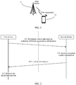
- the embodiments of the present invention are applied to a communications system shown in FIG. 1 .
- the communications system includes a first device and a second device.
- the first device is described by using a base station as an example, and the second device is described by using user equipment as an example.
- the base station 11 sends downlink control information to the user equipment 12.
- the downlink control information includes subframe aggregation information.
- the user equipment 12 sends uplink information to the base station 11 according to the received downlink control information.
- the base station 11 sends, to the user equipment 12, downlink control information for scheduling downlink data
- the user equipment 12 sends, to the base station 11 according to the received downlink control information for scheduling downlink data, hybrid automatic repeat request-acknowledgment information corresponding to the downlink data.
- the base station 11 sends, to the user equipment 12 downlink control information for scheduling uplink data
- the user equipment 12 sends uplink data to the base station 11 according to the received downlink control information for scheduling uplink data.
- the foregoing communications system may be an LTE system or an LTE-advanced system.
- a subframe in all the embodiments of the present invention may be substituted for a transmission time interval TTI.
- steps in all the embodiments of the present invention are not performed in a sequential order and may be independent of each other.
- TDD Time Division Duplex
- TDD-U TDD Universal
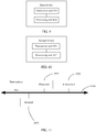
- a frame structure corresponding to the TDD-U system includes not only a downlink subframe, an uplink subframe, and a special subframe in an LTE system, but also introduces two new types of subframes: a first subframe type S1 and a second subframe type S2.
- a subframe S1 and a subframe S2 each include a symbol for downlink transmission, a guard period (English full name: Guard Period, GP for short), and a symbol for uplink transmission.
- the symbol for downlink transmission is mainly used for physical downlink control channel transmission and downlink data transmission
- the symbol for uplink transmission is mainly used for physical uplink control channel (English full name: Physical Uplink Control Channel, PUCCH for short), uplink control information, and channel sounding reference signal (English full name: Sounding Reference Signal, SRS for short) transmission.
- the symbol for downlink transmission is mainly used for physical downlink control channel (English full name: Physical Downlink Control Channel, PDCCH for short) and physical downlink shared channel (English full name: Physical Downlink Shared Channel, PDSCH for short) transmission
- the symbol for uplink transmission is mainly used for physical uplink shared channel (English full name: Physical Uplink Shared Channel, PUSCH for short), PUCCH, and SRS transmission.
- the TDD-U system implements a unified HARQ timing, uplink and downlink rapid HARQ feedbacks, flexible TDD uplink and downlink configurations, and the like by introducing the two new types of subframes.
- the subframe S1 and the subframe S2 each include a guard period GP, and larger quantities of subframes S1 and subframes S2 in a radio frame indicate higher GP overheads. Therefore, gains and overheads caused by the subframes S1 and the subframes S2 need to be well balanced.
- An embodiment of the present invention provides an information transmission method, applied to the foregoing communications system.
- the method may be applied to an LTE system and an LTE-Advanced system.
- the method includes the following steps.
- a first device sends downlink control information to a second device, where the downlink control information includes subframe aggregation information.
- One subframe or a plurality of consecutive subframes are used for data transmission in subframe aggregation.
- different redundancy versions of one transport block full name: Transport Block, TB for short
- Transport Block full name: Transport Block
- the subframe aggregation information in this embodiment of the present invention may be used by the first device to indicate, to the second device, a quantity of subframes used in the subframe aggregation, or may be used by the first device to indicate, to the second device, a redundancy version corresponding to at least one of subframes used in the subframe aggregation, or may be used by the first device to indicate, to the second device, a quantity of subframes used in the subframe aggregation and a redundancy version corresponding to at least one of subframes used in the subframe aggregation.
- the subframe aggregation information may be used by the first device to indicate, to the second device, a quantity of subframes occupied by data transmission scheduled by using the downlink control information, or may be used by the first device to indicate, to the second device, a redundancy version corresponding to at least one of subframes occupied by data transmission scheduled by using the downlink control information, or may be used by the first device to indicate, to the second device, a quantity of subframes occupied by data transmission scheduled by using the downlink control information, and a redundancy version corresponding to at least one of the subframes occupied by the data transmission scheduled by using the downlink control information.
- the downlink control information may be alternatively used to schedule downlink data transmission.
- uplink information in step 103 is a hybrid automatic repeat request-acknowledgment corresponding to the downlink data transmission.
- a subframe aggregation information field in a downlink control information format corresponding to the downlink control information occupies three information bits.
- the 3-bit subframe aggregation information may be used to indicate the quantity of the subframes used in the subframe aggregation and the redundancy version corresponding to at least one of the subframes used in the subframe aggregation. This may be specifically:
- the three information bits occupied by the subframe aggregation information field may include a 2-bit redundancy version and one newly added bit in an existing downlink control information format.
- the quantity of the subframes used in the subframe aggregation is dynamically indicated based on a channel condition by using the subframe aggregation information in the downlink control information, so that resources can be efficiently used, spectrum utilization can be improved, and data transmission reliability can be ensured. For example, it is indicated, to a user whose channel condition is favorable, that the quantity of the subframes used in the subframe aggregation is one, and it is indicated, to a user whose channel condition is poor, that the quantity of the subframes used in the subframe aggregation is four.
- use of consecutive subframes for transmission can reduce a service delay while ensuring transmission reliability. For a user whose channel condition is favorable, use of fewer subframes for transmission can further reduce the service delay. This method can better serve a low-latency and highly-reliable service.
- the quantity of the subframes used in the subframe aggregation and the redundancy versions of the used subframes are jointly indicated by using the subframe aggregation information field, so that typical combined indication is implemented by using only three information bits.
- This compared with a case in which two bits are used to indicate the quantity of the subframes used in the subframe aggregation and two bits are used to indicate the redundancy versions, reduces bit overheads, reduces load of the downlink control information, and improves transmission reliability of the downlink control information.
- the second device receives the downlink control information sent by the first device, where the downlink control information includes the subframe aggregation information.
- the second device sends uplink information according to the downlink control information received in step 102.
- the uplink information may be a hybrid automatic repeat request-acknowledgment corresponding to the downlink data transmission.
- this step may be:
- the first device receives the uplink information sent by the second device according to the downlink control information.
- the first device receives the hybrid automatic repeat request-acknowledgment sent by the second device.
- the hybrid automatic repeat request-acknowledgment is a hybrid automatic repeat request-acknowledgment (English full name: Hybrid Automatic Repeat request ACK, HARQ-ACK for short) corresponding to the downlink data transmission scheduled by using the downlink control information.
- the first device sends the downlink control information to the second device, where the downlink control information includes the subframe aggregation information, so that the second device can obtain, according to the subframe aggregation information, the quantity of the subframes used in the subframe aggregation and/or the redundancy version corresponding to the at least one of the subframes used in the subframe aggregation, or obtain, according to the subframe aggregation information, the redundancy version corresponding to the at least one of the subframes used in the subframe aggregation, or obtain, according to the subframe aggregation information, the quantity of the subframes used in the subframe aggregation and the redundancy version corresponding to the at least one of the subframes used in the subframe aggregation, and perform corresponding processing.
- the quantity of the subframes used in the subframe aggregation is dynamically indicated based on a channel condition, so that resources can be efficiently used, spectrum utilization can be improved, and data transmission reliability can be ensured. For example, it is indicated, to a user whose channel condition is favorable, that the quantity of the subframes used in the subframe aggregation is one, and it is indicated, to a user whose channel condition is poor, that the quantity of the subframes used in the subframe aggregation is four.
- use of consecutive subframes for transmission can reduce a service delay while ensuring transmission reliability. For a user whose channel condition is favorable, use of fewer subframes for transmission can further reduce the service delay. This method can better serve a low-latency and highly-reliable service.
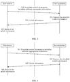
- An embodiment of the present invention provides an information transmission method, applicable to an evolved TDD system, for example, a TDD-U system. As shown in FIG. 3 , the method includes the following steps.
- a first device sends downlink control information to a second device, where the downlink control information includes subframe aggregation information.
- One subframe or a plurality of consecutive subframes are used for data transmission in the subframe aggregation.
- different redundancy versions of one transport block are transmitted by using the plurality of subframes used in the subframe aggregation.
- the subframe aggregation information in this embodiment of the present invention may be used by the first device to indicate, to the second device, a quantity of subframes used in the subframe aggregation and/or a redundancy version corresponding to at least one of subframes used in the subframe aggregation.
- the subframe aggregation information may be used by the first device to indicate, to the second device, a quantity of subframes occupied by data transmission scheduled by using the downlink control information and/or a redundancy version corresponding to at least one of subframes occupied by data transmission scheduled by using the downlink control information.
- the downlink control information may be used to schedule downlink data transmission.
- uplink information in step 203 is a hybrid automatic repeat request-acknowledgment corresponding to the downlink data transmission.
- the subframe aggregation information in this embodiment of the present invention is further used to indicate subframe types of the subframes used in the subframe aggregation.
- the subframe type includes a first subframe type.
- Subframes corresponding to the first subframe type include a time domain symbol used for downlink transmission, a guard period GP, and a time domain symbol used for uplink transmission.
- a quantity of time domain symbols used for downlink transmission is greater than or equal to a quantity of time domain symbols used for uplink transmission.
- the time domain symbol used for uplink transmission may be used for uplink control information transmission, and/or sounding reference signal SRS transmission, and/or uplink data transmission.
- a subframe aggregation information field in a downlink control information format corresponding to the downlink control information occupies four information bits.
- the 4-bit subframe aggregation information may be used to indicate the quantity of the subframes used in the subframe aggregation, the redundancy version corresponding to the at least one of the subframes used in the subframe aggregation, and the subframe types of the subframes used in the subframe aggregation. This may be specifically:
- the downlink control information includes hybrid automatic repeat request-acknowledgment subframe information.
- the hybrid automatic repeat request-acknowledgment subframe information is used to indicate a subframe of the hybrid automatic repeat request-acknowledgment corresponding to the downlink data transmission scheduled by using the downlink control information.
- the four information bits occupied by the subframe aggregation information field may include a 2-bit redundancy version and two newly added bits in an existing downlink control information format.
- the quantity of the subframes used in the subframe aggregation and the redundancy version are indicated based on a channel condition by using the subframe aggregation information in the downlink control information, so that resources can be efficiently used, spectrum utilization can be improved, and data transmission reliability can be ensured. For example, it is indicated, to a user whose channel condition is favorable, that the quantity of the subframes used in the subframe aggregation is one, and it is indicated, to a user whose channel condition is poor, that the quantity of the subframes used in the subframe aggregation is four. Moreover, in this embodiment, use of consecutive subframes for transmission can reduce a service delay while ensuring transmission reliability.
- the subframe aggregation information may be further used to indicate the subframe types of the subframes used in the subframe aggregation, so that locations and quantities of subframes S1 can be flexibly configured according to an actual situation, and system performance is improved by using the S1 subframes while GP overheads are proper.
- the quantity of the subframes used in the subframe aggregation, the redundancy versions of the used subframes, and the subframe types of the used subframes are jointly indicated by using the subframe aggregation information field, so that typical combined indication is implemented by using only four information bits.
- This compared with a case in which two bits are used to indicate the quantity of the subframes used in the subframe aggregation, two bits are used to indicate the redundancy versions, and two bits are used to indicate the subframe types, reduces bit overheads, reduces load of the downlink control information, and improves transmission reliability of the downlink control information.
- the second device receives the downlink control information sent by the first device, where the downlink control information includes the subframe aggregation information.
- a description of the subframe aggregation information is similar to that in step 201. Details are not described herein again.
- the second device sends uplink information according to the downlink control information received in step 202.
- the uplink information may be a hybrid automatic repeat request-acknowledgment corresponding to the downlink data transmission.
- this step may be:
- This step may further include: the second device determines, according to the hybrid automatic repeat request-acknowledgment subframe information in the downlink control information, the subframe of the hybrid automatic repeat request-acknowledgment corresponding to the downlink data transmission scheduled by using the downlink control information; and the second device sends, in the determined subframe of the hybrid automatic repeat request-acknowledgment, the hybrid automatic repeat request-acknowledgment corresponding to the downlink data transmission scheduled by using the downlink control information.
- the first device receives the uplink information sent by the second device according to the downlink control information.
- the first device receives the hybrid automatic repeat request-acknowledgment sent by the second device.
- the hybrid automatic repeat request-acknowledgment is a hybrid automatic repeat request-acknowledgment corresponding to the downlink data transmission scheduled by using the downlink control information.
- the first device sends the downlink control information to the second device, where the downlink control information includes the subframe aggregation information, so that the second device can obtain, according to the subframe aggregation information, the quantity of the subframes used in the subframe aggregation, and/or the redundancy version corresponding to the at least one of the subframes used in the subframe aggregation, and/or the subframe types of the subframes used in the subframe aggregation, and perform corresponding processing.
- the quantity of the subframes used in the subframe aggregation and the redundancy versions of the subframes used in the subframe aggregation are dynamically indicated based on a channel condition, so that resources can be efficiently used, spectrum utilization can be improved, and data transmission reliability can be ensured. For example, it is indicated, to a user whose channel condition is favorable, that the quantity of the subframes used in the subframe aggregation is one, and it is indicated, to a user whose channel condition is poor, that the quantity of the subframes used in the subframe aggregation is four. Moreover, in this embodiment, use of consecutive subframes for transmission can reduce a service delay while ensuring transmission reliability.
- the subframe aggregation information may be further used to indicate the subframe types of the subframes used in the subframe aggregation, so that locations and quantities of subframes S1 can be flexibly configured according to an actual situation, and system performance is improved by using the S1 subframes while GP overheads are proper.
- An embodiment of the present invention provides an information transmission method, applied to the foregoing communications system.
- the method may be applied to an LTE system and an LTE-Advanced system.
- the method includes the following steps.
- a first device sends downlink control information to a second device, where the downlink control information includes subframe aggregation information.
- One subframe or a plurality of consecutive subframes are used for data transmission in the subframe aggregation.
- different redundancy versions of one transport block are transmitted by using the plurality of subframes used in the subframe aggregation.
- the subframe aggregation information in this embodiment of the present invention may be used by the first device to indicate, to the second device, a redundancy version corresponding to at least one of subframes used in the subframe aggregation.
- the subframe aggregation information may be used by the first device to indicate, to the second device, a redundancy version corresponding to at least one of subframes occupied by data transmission scheduled by using the downlink control information.
- the subframe aggregation information corresponds to the redundancy version in the downlink control information; or a redundancy version domain in a downlink control information format corresponding to the downlink control information is a subframe aggregation information field.
- the downlink control information may be used to schedule downlink data transmission.
- uplink information in step 303 is a hybrid automatic repeat request-acknowledgment corresponding to the downlink data transmission.
- this embodiment of the present invention further includes: the first device sends radio resource control signaling to the second device, where the radio resource control signaling is used to indicate the quantity of the subframes used in the subframe aggregation.
- this embodiment of the present invention may further include: the first device scrambles a cyclic redundancy check CRC of the downlink control information by using a radio network temporary identifier RNTI, where the RNTI indicates the quantity of the subframes used in the subframe aggregation, and different RNTIs correspond to different subframe quantities.
- RNTI indicates the quantity of the subframes used in the subframe aggregation, and different RNTIs correspond to different subframe quantities.
- this embodiment of the present invention may further include: the first device scrambles a cyclic redundancy check CRC of the downlink control information by using a radio network temporary identifier RNTI, where the RNTI indicates a transmission time interval TTI length corresponding to a physical downlink shared channel scheduled by using the downlink control information, and different RNTIs correspond to different TTI lengths.
- RNTI indicates a transmission time interval TTI length corresponding to a physical downlink shared channel scheduled by using the downlink control information, and different RNTIs correspond to different TTI lengths.
- this embodiment of the present invention may further include: the first device scrambles a cyclic redundancy check CRC of the downlink control information by using a radio network temporary identifier RNTI, where the RNTI indicates a hybrid automatic repeat request-acknowledgment timing corresponding to a physical downlink shared channel scheduled by using the downlink control information, and different RNTIs correspond to different hybrid automatic repeat request-acknowledgment timings.
- RNTI indicates a hybrid automatic repeat request-acknowledgment timing corresponding to a physical downlink shared channel scheduled by using the downlink control information
- different RNTIs correspond to different hybrid automatic repeat request-acknowledgment timings.
- this embodiment of the present invention may further include: the first device determines, based on the quantity of the subframes used in the subframe aggregation and a redundancy version corresponding to a first subframe in the subframes used in the subframe aggregation, redundancy versions corresponding to remaining subframes in the subframes used in the subframe aggregation, specifically including:
- the second device receives the downlink control information sent by the first device, where the downlink control information includes the subframe aggregation information.
- a description of the subframe aggregation information is similar to that in step 301. Details are not described herein again.
- this embodiment of the present invention may further include: the second device receives the radio resource control signaling sent by the first device, and the second device determines, according to the radio resource control signaling, the quantity of the subframes used in the subframe aggregation.
- this embodiment of the present invention may further include: the second device determines, according to a radio network temporary identifier RNTI used to scramble a cyclic redundancy check CRC of the downlink control information, the quantity of the subframes used in the subframe aggregation, where different RNTIs correspond to different subframe quantities.
- RNTI radio network temporary identifier
- this embodiment of the present invention may further include: the second device determines, according to a radio network temporary identifier RNTI used to scramble a cyclic redundancy check CRC of the downlink control information, a transmission time interval TTI length corresponding to a physical downlink shared channel scheduled by using the downlink control information, where different RNTIs correspond to different TTI lengths.
- RNTI radio network temporary identifier used to scramble a cyclic redundancy check CRC of the downlink control information
- TTI length corresponding to a physical downlink shared channel scheduled by using the downlink control information
- this embodiment of the present invention may further include: the second device determines, according to a radio network temporary identifier RNTI used to scramble a cyclic redundancy check CRC of the downlink control information, a hybrid automatic repeat request-acknowledgment timing corresponding to a physical downlink shared channel scheduled by using the downlink control information, where different RNTIs correspond to different hybrid automatic repeat request-acknowledgment timings.
- RNTI radio network temporary identifier used to scramble a cyclic redundancy check CRC of the downlink control information
- the quantity of the subframes used in the subframe aggregation is indicated by using the RRC signaling or the RNTI, thereby reducing load of the downlink control information, and improving transmission reliability of the downlink control information.
- the second device sends uplink information according to the downlink control information received in step 302.
- the uplink information may be a hybrid automatic repeat request-acknowledgment corresponding to the downlink data transmission.
- this step may further include: the second device determines, based on the quantity of the subframes used in the subframe aggregation and a redundancy version corresponding to a first subframe in the subframes used in the subframe aggregation, redundancy versions corresponding to remaining subframes in the subframes used in the subframe aggregation, specifically including: the second device, uses as a starting point, the redundancy version corresponding to the first subframe in the subframes used in the subframe aggregation, and obtains X redundancy versions in a sequential order of redundancy versions 0, 2, 3, and 1 in a cyclic repetition manner, where X is equal to the quantity of the subframes used in the subframe aggregation, and the X redundancy versions are in a one-to-one correspondence to the subframes used in the subframe aggregation.
- redundancy versions of the four subframes used in the subframe aggregation are sequentially 3, 1, 0, and 2.
- this step may be:
- the first device receives the uplink information sent by the second device according to the downlink control information.
- the first device receives the hybrid automatic repeat request-acknowledgment sent by the second device.
- the hybrid automatic repeat request-acknowledgment is a hybrid automatic repeat request-acknowledgment corresponding to the downlink data transmission scheduled by using the downlink control information.
- the first device sends the downlink control information to the second device, where the downlink control information includes the subframe aggregation information, so that the second device can obtain, according to the subframe aggregation information, the redundancy version corresponding to the at least one of the subframes used in the subframe aggregation.
- the first device sends the RRC signaling to the second device, to indicate the quantity of the subframes used in the subframe aggregation, so that the second device obtains the quantity of the subframes used in the subframe aggregation, and performs corresponding processing. In this way, a service delay is reduced while data transmission reliability is ensured.
- An embodiment of the present invention provides an information transmission method, applied to the foregoing communications system.
- the method may be applied to an LTE system and an LTE-Advanced system.
- the method includes the following steps.
- a first device sends downlink control information to a second device, where the downlink control information includes subframe aggregation information.
- One subframe or a plurality of consecutive subframes are used for data transmission in the subframe aggregation.
- different redundancy versions of one transport block are transmitted by using the plurality of subframes used in the subframe aggregation.
- the subframe aggregation information in this embodiment of the present invention may be used by the first device to indicate, to the second device, a quantity of subframes used in the subframe aggregation and a redundancy version corresponding to at least one of subframes used in the subframe aggregation.
- the subframe aggregation information may be used by the first device to indicate, to the second device, a quantity of subframes occupied by data transmission scheduled by using the downlink control information and a redundancy version corresponding to at least one of subframes occupied by data transmission scheduled by using the downlink control information.
- the downlink control information may be used to schedule uplink data transmission.
- uplink information in step 403 is uplink data scheduled by using the downlink control information.
- a subframe aggregation information field in a downlink control information format corresponding to the downlink control information occupies two information bits. This may be specifically:
- the quantity of the subframes used in the subframe aggregation is dynamically indicated based on a channel condition by using the subframe aggregation information in the downlink control information, so that resources can be efficiently used, spectrum utilization can be improved, and data transmission reliability can be ensured. For example, it is indicated, to a user whose channel condition is favorable, that the quantity of the subframes used in the subframe aggregation is one, and it is indicated, to a user whose channel condition is poor, that the quantity of the subframes used in the subframe aggregation is four.
- use of consecutive subframes for transmission can reduce a service delay while ensuring transmission reliability. For a user whose channel condition is favorable, use of fewer subframes for transmission can further reduce the service delay. This method can better serve a low-latency and highly-reliable service.
- the second device receives the downlink control information sent by the first device, where the downlink control information includes the subframe aggregation information.
- the second device sends uplink information according to the downlink control information received in step 402.
- the downlink control information is used to schedule uplink data transmission, and the uplink information is uplink data scheduled by using the uplink control information.
- this step may be:
- the first device receives the uplink information sent by the second device according to the downlink control information.
- the first device receives the uplink data sent by the second device.
- the first device sends the downlink control information to the second device, where the downlink control information includes the subframe aggregation information, so that the second device can obtain, according to the subframe aggregation information, the quantity of the subframes used in the subframe aggregation and the redundancy version corresponding to the at least one of the subframes used in the subframe aggregation, and perform corresponding processing.
- the quantity of the subframes used in the subframe aggregation is dynamically indicated based on a channel condition, so that resources can be efficiently used, spectrum utilization can be improved, and data transmission reliability can be ensured.
- the quantity of the subframes used in the subframe aggregation is one, and it is indicated, to a user whose channel condition is poor, that the quantity of the subframes used in the subframe aggregation is four.
- use of consecutive subframes for transmission can reduce a service delay while ensuring transmission reliability.
- use of fewer subframes for transmission can further reduce the service delay. This method can better serve a low-latency and highly-reliable service.
- An embodiment of the present invention provides an information transmission method, applicable to an evolved TDD system, for example, a TDD-U system. As shown in FIG. 6 , the method includes the following steps.
- a first device sends downlink control information to a second device, where the downlink control information includes subframe aggregation information.
- One subframe or a plurality of consecutive subframes are used for data transmission in the subframe aggregation.
- different redundancy versions of one transport block are transmitted by using the plurality of subframes used in the subframe aggregation.
- the subframe aggregation information in this embodiment of the present invention may be used by the first device to indicate, to the second device, a quantity of subframes used in the subframe aggregation and a redundancy version corresponding to at least one of subframes used in the subframe aggregation.
- the subframe aggregation information may be used by the first device to indicate, to the second device, a quantity of subframes occupied by data transmission scheduled by using the downlink control information and a redundancy version corresponding to at least one of subframes occupied by data transmission scheduled by using the downlink control information.
- the downlink control information may be used to schedule uplink data transmission.
- uplink information in step 503 is uplink data scheduled by using the downlink control information.
- the subframe aggregation information in this embodiment of the present invention is further used to indicate subframe types of the subframes used in the subframe aggregation.
- the subframe type includes a second subframe type.
- Subframes corresponding to the second subframe type include a time domain symbol used for downlink transmission, a guard period GP, and a time domain symbol used for uplink transmission.
- a quantity of time domain symbols used for downlink transmission is less than a quantity of time domain symbols used for uplink transmission.
- the time domain symbol used for downlink transmission may be used for downlink control information transmission, and/or reference signal and/or downlink data transmission.
- a subframe aggregation information field in a downlink control information format corresponding to the downlink control information in this embodiment of the present invention occupies three information bits. This may be specifically:
- the downlink control information includes hybrid automatic repeat request-acknowledgment subframe information.
- the hybrid automatic repeat request-acknowledgment subframe information is used to indicate a subframe of the hybrid automatic repeat request-acknowledgment corresponding to the uplink data transmission scheduled by using the downlink control information.
- the quantity of the subframes used in the subframe aggregation and the redundancy version are indicated based on a channel condition by using the subframe aggregation information in the downlink control information, so that resources can be efficiently used, spectrum utilization can be improved, and data transmission reliability can be ensured. For example, it is indicated, to a user whose channel condition is favorable, that the quantity of the subframes used in the subframe aggregation is one, and it is indicated, to a user whose channel condition is poor, that the quantity of the subframes used in the subframe aggregation is four. Moreover, in this embodiment, use of consecutive subframes for transmission can reduce a service delay while ensuring transmission reliability.
- the subframe aggregation information may be further used to indicate the subframe types of the subframes used in the subframe aggregation, so that locations and quantities of subframes S2 can be flexibly configured according to an actual situation, and system performance is improved by using the S2 subframes while GP overheads are proper.
- the second device receives the downlink control information sent by the first device, where the downlink control information includes the subframe aggregation information.
- the second device sends uplink information according to the downlink control information received in step 502.
- the downlink control information is used to schedule uplink data transmission, and the uplink information is uplink data scheduled by using the uplink control information.
- this step may be:
- the first device receives the uplink information sent by the second device according to the downlink control information.
- the first device receives the uplink data sent by the second device.
- the first device sends the downlink control information to the second device, where the downlink control information includes the subframe aggregation information, so that the second device can obtain, according to the subframe aggregation information, the quantity of the subframes used in the subframe aggregation, the redundancy version corresponding to the at least one of the subframes used in the subframe aggregation, and the subframe types of the subframes used in the subframe aggregation, and perform corresponding processing.
- the quantity of the subframes used in the subframe aggregation and the redundancy versions of the subframes used in the subframe aggregation are dynamically indicated based on a channel condition, so that resources can be efficiently used, spectrum utilization can be improved, and data transmission reliability can be ensured. For example, it is indicated, to a user whose channel condition is favorable, that the quantity of the subframes used in the subframe aggregation is one, and it is indicated, to a user whose channel condition is poor, that the quantity of the subframes used in the subframe aggregation is four. Moreover, in this embodiment, use of consecutive subframes for transmission can reduce a service delay while ensuring transmission reliability.
- the subframe aggregation information may be further used to indicate the subframe types of the subframes used in the subframe aggregation, so that locations and quantities of subframes S1 can be flexibly configured according to an actual situation, and system performance is improved by using the S1 subframes while GP overheads are proper.
- An embodiment of the present invention provides an information transmission method, applied to the foregoing communications system.
- the method may be applied to an LTE system and an LTE-Advanced system.
- the method includes the following steps.
- a first device sends downlink control information to a second device, where the downlink control information includes subframe aggregation information.
- One subframe or a plurality of consecutive subframes are used for data transmission in the subframe aggregation.
- different redundancy versions of one transport block are transmitted by using the plurality of subframes used in the subframe aggregation.
- coded bits corresponding to the transport block are jointly determined by resources corresponding to the plurality of subframes.
- the subframe aggregation information in this embodiment of the present invention may be used by the first device to indicate, to the second device, a quantity of subframes used in the subframe aggregation and/or subframe types of subframes used in the subframe aggregation.
- the subframe aggregation information may be used by the first device to indicate, to the second device, a quantity of subframes occupied by data transmission scheduled by using the downlink control information and/or subframe types of subframes used in the subframe aggregation.
- the downlink control information may be used to schedule downlink data transmission.
- uplink information in step 603 is a hybrid automatic repeat request-acknowledgment corresponding to the downlink data transmission.
- the downlink control information may be used to schedule uplink data transmission.
- uplink information in step 603 is uplink data scheduled by using the downlink control information.
- a subframe aggregation information field in a downlink control information format corresponding to the downlink control information occupies two information bits.
- the 2-bit subframe aggregation information may be used to indicate the quantity of the subframes used in the subframe aggregation. This may be specifically:
- a last subframe in the subframes used in the subframe aggregation is a first subframe type or a second subframe type. Descriptions of the first subframe type and the second subframe type are similar to those in Embodiment 2 and Embodiment 5. Details are not described herein again.
- the quantity of the subframes used in the subframe aggregation is dynamically indicated based on a channel condition by using the subframe aggregation information in the downlink control information, so that resources can be efficiently used, spectrum utilization can be improved, and data transmission reliability can be ensured. For example, it is indicated, to a user whose channel condition is favorable, that the quantity of the subframes used in the subframe aggregation is one, and it is indicated, to a user whose channel condition is poor, that the quantity of the subframes used in the subframe aggregation is four.
- use of consecutive subframes for transmission can reduce a service delay while ensuring transmission reliability. For a user whose channel condition is favorable, use of fewer subframes for transmission can further reduce the service delay. This method can better serve a low-latency and highly-reliable service.
- the second device receives the downlink control information sent by the first device, where the downlink control information includes the subframe aggregation information.
- the second device sends uplink information according to the downlink control information received in step 602.
- the uplink information may be a hybrid automatic repeat request-acknowledgment corresponding to the downlink data transmission.
- this step may be:
- the downlink control information may be alternatively used to schedule uplink data transmission, and the uplink information is uplink data scheduled by using the uplink control information.
- this step may be:
- the first device receives the uplink information sent by the second device according to the downlink control information.
- the first device receives the hybrid automatic repeat request-acknowledgment sent by the second device.
- the hybrid automatic repeat request-acknowledgment is a hybrid automatic repeat request-acknowledgment corresponding to the downlink data transmission scheduled by using the downlink control information.
- This step may further be: The first device receives the uplink data sent by the second device.
- the first device sends the downlink control information to the second device, where the downlink control information includes the subframe aggregation information, so that the second device can obtain, according to the subframe aggregation information, the quantity of the subframes used in the subframe aggregation and/or the redundancy version corresponding to the at least one of the subframes used in the subframe aggregation, and perform corresponding processing.
- the quantity of the subframes used in the subframe aggregation is dynamically indicated based on a channel condition, so that resources can be efficiently used, spectrum utilization can be improved, and data transmission reliability can be ensured.
- the quantity of the subframes used in the subframe aggregation is one, and it is indicated, to a user whose channel condition is poor, that the quantity of the subframes used in the subframe aggregation is four.
- use of consecutive subframes for transmission can reduce a service delay while ensuring transmission reliability.
- use of fewer subframes for transmission can further reduce the service delay. This method can better serve a low-latency and highly-reliable service.
- only the last subframe in the subframes used in the subframe aggregation is set to a subframe S1 or a subframe S2, thereby reducing GP overheads while ensuring system performance.
- a plurality of subframes send a same redundancy version of a same transport block, so that data coverage can be increased.
- An embodiment of the present invention provides an information transmission method, applied to the foregoing communications system.
- the method may be applied to an LTE system and an LTE-Advanced system.
- the method includes the following steps.
- a first device scrambles a cyclic redundancy check (English full name: Cyclical Redundancy Check, CRC for short) of downlink control information by using a radio network temporary identifier RNTI, and the first device sends the downlink control information to a second device.
- a cyclic redundancy check (English full name: Cyclical Redundancy Check, CRC for short) of downlink control information by using a radio network temporary identifier RNTI
- the downlink control information may be used to schedule downlink data transmission.
- uplink information in step 703 is a hybrid automatic repeat request-acknowledgment corresponding to the downlink data transmission.
- the downlink control information may be used to schedule uplink data transmission.
- uplink information in step 703 is uplink data scheduled by using the downlink control information.
- the RNTI indicates a transmission time interval TTI length corresponding to a physical downlink shared channel scheduled by using the downlink control information, and different RNTIs correspond to different TTI lengths. For example, if the RNTI is a first RNTI, the transmission time interval TTI length corresponding to the physical downlink shared channel scheduled by using the downlink control information is 1 ms. If the RNTI is a second RNTI, the transmission time interval TTI length corresponding to the physical downlink shared channel scheduled by using the downlink control information is two time domain symbols. This method is used to dynamically indicate a TTI length, to perform dynamic scheduling and indication according to a service requirement, so that a low-latency service can be rapidly transmitted. The RNTI is used for indication, so that load of the downlink control information is not increased, thereby improving transmission performance of the downlink control information.
- the RNTI indicates a hybrid automatic repeat request-acknowledgment timing corresponding to a physical downlink shared channel scheduled by using the downlink control information, and different RNTIs correspond to different hybrid automatic repeat request-acknowledgment timings. For example, if the RNTI is a first RNTI, the physical downlink shared channel scheduled by using the downlink control information corresponds to a first HARQ timing. If the RNTI is a second RNTI, the physical downlink shared channel scheduled by using the downlink control information corresponds to a second HARQ timing.
- This method is used to dynamically indicate different HARQ timings, and a short HARQ timing may be indicated for a low-latency service, thereby reducing a service delay; or a corresponding HARQ timing is indicated based on a UE capability, thereby enabling a system to use a short HARQ timing as much as possible, and improving system performance.
- the RNTI is used for indication, so that load of the downlink control information is not increased, thereby improving transmission performance of the downlink control information.
- the second device receives the downlink control information sent by the first device.
- This step may further include: the second device determines, according to the radio network temporary identifier RNTI used to scramble the cyclic redundancy check CRC of the downlink control information, a transmission time interval TTI length corresponding to a physical downlink shared channel scheduled by using the downlink control information, where different RNTIs correspond to different TTI lengths.
- this step may further include: the second device determines, according to the radio network temporary identifier RNTI used to scramble the cyclic redundancy check CRC of the downlink control information, a hybrid automatic repeat request-acknowledgment timing corresponding to a physical downlink shared channel scheduled by using the downlink control information, where different RNTIs correspond to different hybrid automatic repeat request-acknowledgment timings.
- the radio network temporary identifier RNTI used to scramble the cyclic redundancy check CRC of the downlink control information
- a hybrid automatic repeat request-acknowledgment timing corresponding to a physical downlink shared channel scheduled by using the downlink control information, where different RNTIs correspond to different hybrid automatic repeat request-acknowledgment timings.
- the second device sends uplink information according to the downlink control information received in step 702.
- the uplink information may be a hybrid automatic repeat request-acknowledgment corresponding to the downlink data transmission.
- this step may be:
- the uplink information may be a hybrid automatic repeat request-acknowledgment corresponding to the downlink data transmission.
- this step may be:
- the downlink control information may be alternatively used to schedule uplink data transmission, and the uplink information is uplink data scheduled by using the uplink control information.
- this step may be:
- the first device receives the uplink information sent by the second device according to the downlink control information.
- the first device receives the hybrid automatic repeat request-acknowledgment sent by the second device.
- the hybrid automatic repeat request-acknowledgment is a hybrid automatic repeat request-acknowledgment (HARQ-ACK) corresponding to the downlink data transmission scheduled by using the downlink control information.
- HARQ-ACK hybrid automatic repeat request-acknowledgment
- This step may further be: The first device receives the uplink data sent by the second device.
- the first device sends the downlink control information to the second device, to indicate, by using the RNTI of the downlink control information, the hybrid automatic repeat request-acknowledgment timing corresponding to the physical downlink shared channel scheduled by using the downlink control information, so that different HARQ timings are dynamically indicated, and a short HARQ timing may be indicated for a low-latency service, thereby reducing a service delay; or a corresponding HARQ timing is indicated based on a UE capability, thereby enabling a system to use a short HARQ timing as much as possible, and improving system performance.
- the RNTI is used for indication, so that load of the downlink control information is not increased, thereby improving transmission performance of the downlink control information.
- the first device sends the downlink control information to the second device, to indicate, by using the RNTI of the downlink control information, the transmission time interval TTI length corresponding to the physical downlink shared channel scheduled by using the downlink control information.
- the TTI length is dynamically indicated, to perform dynamic scheduling and indication according to a service requirement, so that a low-latency service can be rapidly transmitted.
- the RNTI is used for indication, so that load of the downlink control information is not increased, thereby improving transmission performance of the downlink control information.
- an embodiment of the present invention provides an apparatus, configured to implement the information transmission method provided in the foregoing embodiment.
- the apparatus may be a first device, including: a transceiver unit 801 and a processing unit 802.
- the processing unit 802 is configured to generate downlink control information, where the downlink control information includes subframe aggregation information, and the subframe aggregation information is used by the first device to indicate, to a second device, a quantity of subframes used in subframe aggregation and/or a redundancy version corresponding to at least one of subframes used in subframe aggregation.
- One subframe or a plurality of consecutive subframes are used for data transmission in the subframe aggregation.
- different redundancy versions of one transport block full name: Transport Block, TB for short
- the subframe aggregation information in this embodiment of the present invention may be used by the first device to indicate, to the second device, a quantity of subframes used in the subframe aggregation and/or a redundancy version corresponding to at least one of subframes used in the subframe aggregation.
- the subframe aggregation information may be used by the first device to indicate, to the second device, a quantity of subframes occupied by data transmission scheduled by using the downlink control information and/or a redundancy version corresponding to at least one of subframes occupied by data transmission scheduled by using the downlink control information.
- the downlink control information may be used to schedule downlink data transmission.
- uplink information is a hybrid automatic repeat request-acknowledgment corresponding to the downlink data transmission.
- a subframe aggregation information field in a downlink control information format corresponding to the downlink control information occupies three information bits.
- the 3-bit subframe aggregation information may be used to indicate the quantity of the subframes used in the subframe aggregation and the redundancy version corresponding to at least one of the subframes used in the subframe aggregation. This may be specifically:
- the three information bits occupied by the subframe aggregation information field may include a 2-bit redundancy version and one newly added bit in an existing downlink control information format.
- the quantity of the subframes used in the subframe aggregation is dynamically indicated based on a channel condition by using the subframe aggregation information in the downlink control information, so that resources can be efficiently used, spectrum utilization can be improved, and data transmission reliability can be ensured. For example, it is indicated, to a user whose channel condition is favorable, that the quantity of the subframes used in the subframe aggregation is one, and it is indicated, to a user whose channel condition is poor, that the quantity of the subframes used in the subframe aggregation is four. Moreover, in this embodiment, use of consecutive subframes for transmission can reduce a service delay while ensuring transmission reliability. For a user whose channel condition is favorable, use of fewer subframes for transmission can further reduce the service delay. This method can better serve a low-latency and highly-reliable service.
- the quantity of the subframes used in the subframe aggregation and the redundancy versions of the used subframes are jointly indicated by using the subframe aggregation information field, so that typical combined indication is implemented by using only three information bits.
- This compared with a case in which two bits are used to indicate the quantity of the subframes used in the subframe aggregation and two bits are used to indicate the redundancy versions, reduces bit overheads, reduces load of the downlink control information, and improves transmission reliability of the downlink control information.
- the transceiver unit 801 is configured to: send the downlink control information to the second device, and receive uplink information sent by the second device according to the downlink control information.
- the transceiver unit 801 receives a hybrid automatic repeat request-acknowledgment sent by the second device.
- the hybrid automatic repeat request-acknowledgment is a hybrid automatic repeat request-acknowledgment (English full name: Hybrid Automatic Repeat request ACK, HARQ-ACK for short) corresponding to the downlink data transmission scheduled by using the downlink control information.
- the first device sends the downlink control information to the second device, where the downlink control information includes the subframe aggregation information, so that the second device can obtain, according to the subframe aggregation information, the quantity of the subframes used in the subframe aggregation and/or the redundancy version corresponding to the at least one of the subframes used in the subframe aggregation, and perform corresponding processing.
- the quantity of the subframes used in the subframe aggregation is dynamically indicated based on a channel condition, so that resources can be efficiently used, spectrum utilization can be improved, and data transmission reliability can be ensured.
- the quantity of the subframes used in the subframe aggregation is one, and it is indicated, to a user whose channel condition is poor, that the quantity of the subframes used in the subframe aggregation is four.
- use of consecutive subframes for transmission can reduce a service delay while ensuring transmission reliability.
- use of fewer subframes for transmission can further reduce the service delay. This method can better serve a low-latency and highly-reliable service.
- the first device is applicable to an evolved TDD system, for example, a TDD-U system.
- the processing unit 802 is further configured to generate downlink control information, where the downlink control information includes subframe aggregation information.
- the transceiver unit 801 is further configured to send the downlink control information to the second device.
- One subframe or a plurality of consecutive subframes are used for data transmission in the subframe aggregation.
- different redundancy versions of one transport block are transmitted by using the plurality of subframes used in the subframe aggregation.
- the subframe aggregation information in this embodiment of the present invention may be used by the first device to indicate, to the second device, a quantity of subframes used in the subframe aggregation and/or a redundancy version corresponding to at least one of subframes used in the subframe aggregation.
- the subframe aggregation information may be used by the first device to indicate, to the second device, a quantity of subframes occupied by data transmission scheduled by using the downlink control information and/or a redundancy version corresponding to at least one of subframes occupied by data transmission scheduled by using the downlink control information.
- the downlink control information may be used to schedule downlink data transmission.
- uplink information is a hybrid automatic repeat request-acknowledgment corresponding to the downlink data transmission.
- the subframe aggregation information in this embodiment of the present invention is further used to indicate subframe types of the subframes used in the subframe aggregation.
- the subframe type includes a first subframe type.
- Subframes corresponding to the first subframe type include a time domain symbol used for downlink transmission, a guard period GP, and a time domain symbol used for uplink transmission.
- a quantity of time domain symbols used for downlink transmission is greater than or equal to a quantity of time domain symbols used for uplink transmission.
- the time domain symbol used for uplink transmission may be used for uplink control information transmission, and/or sounding reference signal SRS transmission, and/or uplink data transmission.
- a subframe aggregation information field in a downlink control information format corresponding to the downlink control information occupies four information bits.
- the 4-bit subframe aggregation information may be used to indicate the quantity of the subframes used in the subframe aggregation, the redundancy version corresponding to the at least one of the subframes used in the subframe aggregation, and the subframe types of the subframes used in the subframe aggregation. This may be specifically:
- the downlink control information includes hybrid automatic repeat request-acknowledgment subframe information.
- the hybrid automatic repeat request-acknowledgment subframe information is used to indicate a subframe of the hybrid automatic repeat request-acknowledgment corresponding to the downlink data transmission scheduled by using the downlink control information.
- the four information bits occupied by the subframe aggregation information field may include a 2-bit redundancy version and two newly added bits in an existing downlink control information format.
- the quantity of the subframes used in the subframe aggregation and the redundancy version are indicated based on a channel condition by using the subframe aggregation information in the downlink control information, so that resources can be efficiently used, spectrum utilization can be improved, and data transmission reliability can be ensured. For example, it is indicated, to a user whose channel condition is favorable, that the quantity of the subframes used in the subframe aggregation is one, and it is indicated, to a user whose channel condition is poor, that the quantity of the subframes used in the subframe aggregation is four. Moreover, in this embodiment, use of consecutive subframes for transmission can reduce a service delay while ensuring transmission reliability.
- the subframe aggregation information may be further used to indicate the subframe types of the subframes used in the subframe aggregation, so that locations and quantities of subframes S1 can be flexibly configured according to an actual situation, and system performance is improved by using the S1 subframes while GP overheads are proper.
- the quantity of the subframes used in the subframe aggregation, the redundancy versions of the used subframes, and the subframe types of the used subframes are jointly indicated by using the subframe aggregation information field, so that typical combined indication is implemented by using only four information bits.
- This compared with a case in which two bits are used to indicate the quantity of the subframes used in the subframe aggregation, two bits are used to indicate the redundancy versions, and two bits are used to indicate the subframe types, reduces bit overheads, reduces load of the downlink control information, and improves transmission reliability of the downlink control information.
- the transceiver unit 801 is specifically configured to receive the uplink information sent by the second device according to the downlink control information.
- the hybrid automatic repeat request-acknowledgment is a hybrid automatic repeat request-acknowledgment corresponding to the downlink data transmission scheduled by using the downlink control information.
- the first device sends the downlink control information to the second device, where the downlink control information includes the subframe aggregation information, so that the second device can obtain, according to the subframe aggregation information, the quantity of the subframes used in the subframe aggregation, and/or the redundancy version corresponding to the at least one of the subframes used in the subframe aggregation, and/or the subframe types of the subframes used in the subframe aggregation, and perform corresponding processing.
- the quantity of the subframes used in the subframe aggregation and the redundancy versions of the subframes used in the subframe aggregation are dynamically indicated based on a channel condition, so that resources can be efficiently used, spectrum utilization can be improved, and data transmission reliability can be ensured. For example, it is indicated, to a user whose channel condition is favorable, that the quantity of the subframes used in the subframe aggregation is one, and it is indicated, to a user whose channel condition is poor, that the quantity of the subframes used in the subframe aggregation is four. Moreover, in this embodiment, use of consecutive subframes for transmission can reduce a service delay while ensuring transmission reliability.
- the subframe aggregation information may be further used to indicate the subframe types of the subframes used in the subframe aggregation, so that locations and quantities of subframes S1 can be flexibly configured according to an actual situation, and system performance is improved by using the S1 subframes while GP overheads are proper.
- the first device is applicable to the foregoing communications system, for example, applicable to an LTE system and an LTE-Advanced system.
- the transceiver unit 801 is specifically configured to send the downlink control information to the second device, where the downlink control information includes the subframe aggregation information.
- One subframe or a plurality of consecutive subframes are used for data transmission in the subframe aggregation.
- different redundancy versions of one transport block are transmitted by using the plurality of subframes used in the subframe aggregation.
- the subframe aggregation information in this embodiment of the present invention may be used by the first device to indicate, to the second device, a redundancy version corresponding to at least one of subframes used in the subframe aggregation.
- the subframe aggregation information may be used by the first device to indicate, to the second device, a redundancy version corresponding to at least one of subframes occupied by data transmission scheduled by using the downlink control information.
- the subframe aggregation information corresponds to the redundancy version in the downlink control information; or a redundancy version domain in a downlink control information format corresponding to the downlink control information is the subframe aggregation information field.
- the downlink control information may be used to schedule downlink data transmission.
- uplink information is a hybrid automatic repeat request-acknowledgment corresponding to the downlink data transmission.
- the transceiver unit 801 is further configured to send radio resource control signaling to the second device, where the radio resource control signaling is used to indicate the quantity of the subframes used in the subframe aggregation.
- the processing unit 802 is further configured to scramble a cyclic redundancy check CRC of the downlink control information by using a radio network temporary identifier RNTI, where the RNTI indicates the quantity of the subframes used in the subframe aggregation, and different RNTIs correspond to different subframe quantities.
- RNTI indicates the quantity of the subframes used in the subframe aggregation, and different RNTIs correspond to different subframe quantities.
- the processing unit 802 is further configured to: scramble a cyclic redundancy check CRC of the downlink control information by using a radio network temporary identifier RNTI, where the RNTI indicates a transmission time interval TTI length corresponding to a physical downlink shared channel scheduled by using the downlink control information, and different RNTIs correspond to different TTI lengths.
- RNTI indicates a transmission time interval TTI length corresponding to a physical downlink shared channel scheduled by using the downlink control information, and different RNTIs correspond to different TTI lengths.
- the processing unit 802 is further configured to: scramble a cyclic redundancy check CRC of the downlink control information by using a radio network temporary identifier RNTI, where the RNTI indicates a hybrid automatic repeat request-acknowledgment timing corresponding to a physical downlink shared channel scheduled by using the downlink control information, and different RNTIs correspond to different hybrid automatic repeat request-acknowledgment timings.
- RNTI indicates a hybrid automatic repeat request-acknowledgment timing corresponding to a physical downlink shared channel scheduled by using the downlink control information
- different RNTIs correspond to different hybrid automatic repeat request-acknowledgment timings.
- the processing unit 802 is further configured to: determine, based on the quantity of the subframes used in the subframe aggregation and a redundancy version corresponding to a first subframe in the subframes used in the subframe aggregation, redundancy versions corresponding to remaining subframes in the subframes used in the subframe aggregation, specifically including:
- the transceiver unit 801 is specifically configured to receive the uplink information sent by the second device according to the downlink control information.
- the transceiver unit 801 receives the hybrid automatic repeat request-acknowledgment sent by the second device.
- the hybrid automatic repeat request-acknowledgment is a hybrid automatic repeat request-acknowledgment corresponding to the downlink data transmission scheduled by using the downlink control information.
- the first device sends the downlink control information to the second device, where the downlink control information includes the subframe aggregation information, so that the second device can obtain, according to the subframe aggregation information, the redundancy version corresponding to the at least one of the subframes used in the subframe aggregation.
- the first device sends the RRC signaling to the second device, to indicate the quantity of the subframes used in the subframe aggregation, so that the second device obtains the quantity of the subframes used in the subframe aggregation, and performs corresponding processing. In this way, a service delay is reduced while data transmission reliability is ensured.
- the first device is applied to the foregoing communications system, for example, applicable to an LTE system and an LTE-Advanced system.
- the transceiver unit 801 may be specifically configured to send the downlink control information to the second device, where the downlink control information includes the subframe aggregation information.
- One subframe or a plurality of consecutive subframes are used for data transmission in the subframe aggregation.
- different redundancy versions of one transport block are transmitted by using the plurality of subframes used in the subframe aggregation.
- the subframe aggregation information in this embodiment of the present invention may be used by the first device to indicate, to the second device, a quantity of subframes used in the subframe aggregation and/or a redundancy version corresponding to at least one of subframes used in the subframe aggregation.
- the subframe aggregation information may be used by the first device to indicate, to the second device, a quantity of subframes occupied by data transmission scheduled by using the downlink control information and/or a redundancy version corresponding to at least one of subframes occupied by data transmission scheduled by using the downlink control information.
- the downlink control information may be used to schedule uplink data transmission.
- uplink information is uplink data scheduled by using the downlink control information.
- a subframe aggregation information field in a downlink control information format corresponding to the downlink control information occupies two information bits. This may be specifically:
- the quantity of the subframes used in the subframe aggregation is dynamically indicated based on a channel condition by using the subframe aggregation information in the downlink control information, so that resources can be efficiently used, spectrum utilization can be improved, and data transmission reliability can be ensured. For example, it is indicated, to a user whose channel condition is favorable, that the quantity of the subframes used in the subframe aggregation is one, and it is indicated, to a user whose channel condition is poor, that the quantity of the subframes used in the subframe aggregation is four. Moreover, in this embodiment, use of consecutive subframes for transmission can reduce a service delay while ensuring transmission reliability. For a user whose channel condition is favorable, use of fewer subframes for transmission can further reduce the service delay. This method can better serve a low-latency and highly-reliable service.
- the transceiver unit 801 may be specifically configured to receive the uplink information sent by the second device according to the downlink control information.
- the transceiver unit 801 receives uplink data sent by the second device.
- the first device sends the downlink control information to the second device, where the downlink control information includes the subframe aggregation information, so that the second device can obtain, according to the subframe aggregation information, the quantity of the subframes used in the subframe aggregation and/or the redundancy version corresponding to the at least one of the subframes used in the subframe aggregation, and perform corresponding processing.
- the quantity of the subframes used in the subframe aggregation is dynamically indicated based on a channel condition, so that resources can be efficiently used, spectrum utilization can be improved, and data transmission reliability can be ensured.
- the quantity of the subframes used in the subframe aggregation is one, and it is indicated, to a user whose channel condition is poor, that the quantity of the subframes used in the subframe aggregation is four.
- use of consecutive subframes for transmission can reduce a service delay while ensuring transmission reliability.
- use of fewer subframes for transmission can further reduce the service delay. This method can better serve a low-latency and highly-reliable service.
- the first device is applied to an evolved TDD system, for example, a TDD-U system.
- the transceiver unit 801 may be specifically configured to send the downlink control information to the second device, where the downlink control information includes the subframe aggregation information.
- One subframe or a plurality of consecutive subframes are used for data transmission in the subframe aggregation.
- different redundancy versions of one transport block are transmitted by using the plurality of subframes used in the subframe aggregation.
- the subframe aggregation information in this embodiment of the present invention may be used by the first device to indicate, to the second device, a quantity of subframes used in the subframe aggregation and/or a redundancy version corresponding to at least one of subframes used in the subframe aggregation.
- the subframe aggregation information may be used by the first device to indicate, to the second device, a quantity of subframes occupied by data transmission scheduled by using the downlink control information and/or a redundancy version corresponding to at least one of subframes occupied by data transmission scheduled by using the downlink control information.
- the downlink control information may be used to schedule uplink data transmission.
- uplink information is uplink data scheduled by using the downlink control information.
- the subframe aggregation information in this embodiment of the present invention is further used to indicate subframe types of the subframes used in the subframe aggregation.
- the subframe type includes a second subframe type.
- Subframes corresponding to the second subframe type include a time domain symbol used for downlink transmission, a guard period GP, and a time domain symbol used for uplink transmission.
- a quantity of time domain symbols used for downlink transmission is less than a quantity of time domain symbols used for uplink transmission.
- the time domain symbol used for downlink transmission may be used for downlink control information transmission, and/or reference signal and/or downlink data transmission.
- a subframe aggregation information field in a downlink control information format corresponding to the downlink control information in this embodiment of the present invention occupies three information bits. This may be specifically:
- the downlink control information includes hybrid automatic repeat request-acknowledgment subframe information.
- the hybrid automatic repeat request-acknowledgment subframe information is used to indicate a subframe of the hybrid automatic repeat request-acknowledgment corresponding to the uplink data transmission scheduled by using the downlink control information.
- the quantity of the subframes used in the subframe aggregation and the redundancy version are indicated based on a channel condition by using the subframe aggregation information in the downlink control information, so that resources can be efficiently used, spectrum utilization can be improved, and data transmission reliability can be ensured. For example, it is indicated, to a user whose channel condition is favorable, that the quantity of the subframes used in the subframe aggregation is one, and it is indicated, to a user whose channel condition is poor, that the quantity of the subframes used in the subframe aggregation is four. Moreover, in this embodiment, use of consecutive subframes for transmission can reduce a service delay while ensuring transmission reliability.
- the subframe aggregation information may be further used to indicate the subframe types of the subframes used in the subframe aggregation, so that locations and quantities of subframes S2 can be flexibly configured according to an actual situation, and system performance is improved by using the S2 subframes while GP overheads are proper.
- the transceiver unit 801 may be specifically configured to receive the uplink information sent by the second device according to the downlink control information.
- the transceiver unit 801 receives the uplink data sent by the second device.
- the first device sends the downlink control information to the second device, where the downlink control information includes the subframe aggregation information, so that the second device can obtain, according to the subframe aggregation information, the quantity of the subframes used in the subframe aggregation, and/or the redundancy version corresponding to the at least one of the subframes used in the subframe aggregation, and/or the subframe types of the subframes used in the subframe aggregation, and perform corresponding processing.
- the quantity of the subframes used in the subframe aggregation and the redundancy versions of the subframes used in the subframe aggregation are dynamically indicated based on a channel condition, so that resources can be efficiently used, spectrum utilization can be improved, and data transmission reliability can be ensured. For example, it is indicated, to a user whose channel condition is favorable, that the quantity of the subframes used in the subframe aggregation is one, and it is indicated, to a user whose channel condition is poor, that the quantity of the subframes used in the subframe aggregation is four. Moreover, in this embodiment, use of consecutive subframes for transmission can reduce a service delay while ensuring transmission reliability.
- the subframe aggregation information may be further used to indicate the subframe types of the subframes used in the subframe aggregation, so that locations and quantities of subframes S1 can be flexibly configured according to an actual situation, and system performance is improved by using the S1 subframes while GP overheads are proper.
- the first device is applied to the foregoing communications system, for example, applicable to an LTE system and an LTE-Advanced system.
- the transceiver unit 801 may be specifically configured to send the downlink control information to the second device, where the downlink control information includes the subframe aggregation information.
- One subframe or a plurality of consecutive subframes are used for data transmission in the subframe aggregation.
- different redundancy versions of one transport block are transmitted by using the plurality of subframes used in the subframe aggregation.
- coded bits corresponding to the transport block are jointly determined by resources corresponding to the plurality of subframes.
- the subframe aggregation information in this embodiment of the present invention may be used by the first device to indicate, to the second device, a quantity of subframes used in the subframe aggregation and/or subframe types of subframes used in the subframe aggregation.
- the subframe aggregation information may be used by the first device to indicate, to the second device, a quantity of subframes occupied by data transmission scheduled by using the downlink control information and/or subframe types of subframes used in the subframe aggregation.
- the downlink control information may be used to schedule downlink data transmission.
- uplink information is a hybrid automatic repeat request-acknowledgment corresponding to the downlink data transmission.
- the downlink control information may be used to schedule uplink data transmission.
- uplink information is uplink data scheduled by using the downlink control information.
- a subframe aggregation information field in a downlink control information format corresponding to the downlink control information occupies two information bits.
- the 2-bit subframe aggregation information may be used to indicate the quantity of the subframes used in the subframe aggregation. This may be specifically:
- a last subframe in the subframes used in the subframe aggregation is a first subframe type or a second subframe type. Descriptions of the first subframe type and the second subframe type are similar to those in Embodiment 2 and Embodiment 5. Details are not described herein again.
- the quantity of the subframes used in the subframe aggregation is dynamically indicated based on a channel condition by using the subframe aggregation information in the downlink control information, so that resources can be efficiently used, spectrum utilization can be improved, and data transmission reliability can be ensured. For example, it is indicated, to a user whose channel condition is favorable, that the quantity of the subframes used in the subframe aggregation is one, and it is indicated, to a user whose channel condition is poor, that the quantity of the subframes used in the subframe aggregation is four. Moreover, in this embodiment, use of consecutive subframes for transmission can reduce a service delay while ensuring transmission reliability. For a user whose channel condition is favorable, use of fewer subframes for transmission can further reduce the service delay. This method can better serve a low-latency and highly-reliable service.
- the transceiver unit 801 may be specifically configured to receive the uplink information sent by the second device according to the downlink control information.
- the transceiver unit 801 receives the hybrid automatic repeat request-acknowledgment sent by the second device.
- the hybrid automatic repeat request-acknowledgment is a hybrid automatic repeat request-acknowledgment corresponding to the downlink data transmission scheduled by using the downlink control information.
- the transceiver unit 801 receives the uplink data sent by the second device.
- the first device sends the downlink control information to the second device, where the downlink control information includes the subframe aggregation information, so that the second device can obtain, according to the subframe aggregation information, the quantity of the subframes used in the subframe aggregation and/or the redundancy version corresponding to the at least one of the subframes used in the subframe aggregation, and perform corresponding processing.
- the quantity of the subframes used in the subframe aggregation is dynamically indicated based on a channel condition, so that resources can be efficiently used, spectrum utilization can be improved, and data transmission reliability can be ensured.
- the quantity of the subframes used in the subframe aggregation is one, and it is indicated, to a user whose channel condition is poor, that the quantity of the subframes used in the subframe aggregation is four.
- use of consecutive subframes for transmission can reduce a service delay while ensuring transmission reliability.
- use of fewer subframes for transmission can further reduce the service delay. This method can better serve a low-latency and highly-reliable service.
- only the last subframe in the subframes used in the subframe aggregation is set to a subframe S1 or a subframe S2, thereby reducing GP overheads while ensuring system performance.
- a plurality of subframes send a same redundancy version of a same transport block, so that data coverage can be increased.
- the first device is applied to the foregoing communications system, for example, applicable to an LTE system and an LTE-Advanced system.
- the processing unit 802 may be specifically configured to scramble a cyclic redundancy check (English full name: Cyclical Redundancy Check, CRC for short) of the downlink control information by using a radio network temporary identifier RNTI.
- the first device sends the downlink control information to the second device.
- the downlink control information may be used to schedule downlink data transmission.
- uplink information is a hybrid automatic repeat request-acknowledgment corresponding to the downlink data transmission.
- the downlink control information may be used to schedule uplink data transmission.
- uplink information is uplink data scheduled by using the downlink control information.
- the RNTI indicates a transmission time interval TTI length corresponding to a physical downlink shared channel scheduled by using the downlink control information, and different RNTIs correspond to different TTI lengths. For example, if the RNTI is a first RNTI, the transmission time interval TTI length corresponding to the physical downlink shared channel scheduled by using the downlink control information is 1 ms. If the RNTI is a second RNTI, the transmission time interval TTI length corresponding to the physical downlink shared channel scheduled by using the downlink control information is two time domain symbols.
- This apparatus is used to dynamically indicate a TTI length, to perform dynamic scheduling and indication according to a service requirement, so that a low-latency service can be rapidly transmitted.
- the RNTI is used for indication, so that load of the downlink control information is not increased, thereby improving transmission performance of the downlink control information.
- the RNTI indicates a hybrid automatic repeat request-acknowledgment timing corresponding to a physical downlink shared channel scheduled by using the downlink control information, and different RNTIs correspond to different hybrid automatic repeat request-acknowledgment timings. For example, if the RNTI is a first RNTI, the physical downlink shared channel scheduled by using the downlink control information corresponds to a first HARQ timing. If the RNTI is a second RNTI, the physical downlink shared channel scheduled by using the downlink control information corresponds to a second HARQ timing.
- This apparatus is used to dynamically indicate different HARQ timings, and a short HARQ timing may be indicated for a low-latency service, thereby reducing a service delay; or a corresponding HARQ timing is indicated based on a UE capability, thereby enabling a system to use a short HARQ timing as much as possible, and improving system performance.
- the RNTI is used for indication, so that load of the downlink control information is not increased, thereby improving transmission performance of the downlink control information.
- the transceiver unit 801 may be specifically configured to receive the uplink information sent by the second device according to the downlink control information.
- the transceiver unit 801 receives the hybrid automatic repeat request-acknowledgment sent by the second device.
- the hybrid automatic repeat request-acknowledgment is a hybrid automatic repeat request-acknowledgment (HARQ-ACK) corresponding to the downlink data transmission scheduled by using the downlink control information.
- HARQ-ACK hybrid automatic repeat request-acknowledgment
- the transceiver unit 801 receives the uplink data sent by the second device.
- the first device sends the downlink control information to the second device, to indicate, by using the RNTI of the downlink control information, the hybrid automatic repeat request-acknowledgment timing corresponding to the physical downlink shared channel scheduled by using the downlink control information, so that different HARQ timings are dynamically indicated, and a short HARQ timing may be indicated for a low-latency service, thereby reducing a service delay; or a corresponding HARQ timing is indicated based on a UE capability, thereby enabling a system to use a short HARQ timing as much as possible, and improving system performance.
- the RNTI is used for indication, so that load of the downlink control information is not increased, thereby improving transmission performance of the downlink control information.
- the first device sends the downlink control information to the second device, to indicate, by using the RNTI of the downlink control information, the transmission time interval TTI length corresponding to the physical downlink shared channel scheduled by using the downlink control information.
- the TTI length is dynamically indicated, to perform dynamic scheduling and indication according to a service requirement, so that a low-latency service can be rapidly transmitted.
- the RNTI is used for indication, so that load of the downlink control information is not increased, thereby improving transmission performance of the downlink control information.
- an embodiment of the present invention provides an apparatus, configured to implement the information transmission method provided in the foregoing embodiment.
- the apparatus may be a second device, and may include:
- the quantity of the subframes used in the subframe aggregation and/or the redundancy version corresponding to the at least one of the subframes used in the subframe aggregation is determined according to the subframe aggregation information.
- the second device decodes, according to the determined quantity of the subframes used in the subframe aggregation and/or the determined redundancy version corresponding to the at least one of the subframes used in the subframe aggregation, downlink data transmission scheduled by using the downlink control information.
- the second device determines, according to a result of the decoding of the downlink data transmission scheduled by using the downlink control information, a hybrid automatic repeat request-acknowledgment corresponding to the downlink data transmission, and sends the determined hybrid automatic repeat request-acknowledgment corresponding to the downlink data transmission.
- the first device sends the downlink control information to the second device, where the downlink control information includes the subframe aggregation information, so that the second device can obtain, according to the subframe aggregation information, the quantity of the subframes used in the subframe aggregation and/or the redundancy version corresponding to the at least one of the subframes used in the subframe aggregation, and perform corresponding processing.
- the quantity of the subframes used in the subframe aggregation is dynamically indicated based on a channel condition, so that resources can be efficiently used, spectrum utilization can be improved, and data transmission reliability can be ensured.
- the quantity of the subframes used in the subframe aggregation is one, and it is indicated, to a user whose channel condition is poor, that the quantity of the subframes used in the subframe aggregation is four.
- use of consecutive subframes for transmission can reduce a service delay while ensuring transmission reliability.
- use of fewer subframes for transmission can further reduce the service delay. This method can better serve a low-latency and highly-reliable service.
- the second device is applicable to an evolved TDD system, for example, a TDD-U system.
- the transceiver unit 901 may be specifically configured to receive the downlink control information sent by the first device, where the downlink control information includes the subframe aggregation information.
- the processing unit 902 is specifically configured to generate the uplink information according to the downlink control information received by the transceiver unit 901.
- the transceiver unit 901 is specifically configured to send the uplink information.
- the uplink information may be a hybrid automatic repeat request-acknowledgment corresponding to the downlink data transmission.
- the processing unit 902 is further configured to: determine, according to the subframe aggregation information, the quantity of the subframes used in the subframe aggregation, the redundancy version corresponding to the at least one of the subframes used in the subframe aggregation, and subframe types of the subframes used in the subframe aggregation; decode, according to the determined quantity of the subframes used in the subframe aggregation, the determined redundancy version corresponding to the at least one of the subframes used in the subframe aggregation, and the determined subframe types of the subframes used in the subframe aggregation, the downlink data transmission scheduled by using the downlink control information; and determine, according to a result of the decoding of the downlink data transmission scheduled by using the downlink control information, a hybrid automatic repeat request-acknowledgment corresponding to the downlink data transmission, and send the determined hybrid automatic repeat request-acknowledgment corresponding to the downlink data transmission.
- processing unit 902 is further configured to: determine, according to hybrid automatic repeat request-acknowledgment subframe information in the downlink control information, a subframe of the hybrid automatic repeat request-acknowledgment corresponding to the downlink data transmission scheduled by using the downlink control information; and send, in the determined subframe of the hybrid automatic repeat request-acknowledgment, the hybrid automatic repeat request-acknowledgment corresponding to the downlink data transmission scheduled by using the downlink control information.
- the first device sends the downlink control information to the second device, where the downlink control information includes the subframe aggregation information, so that the second device can obtain, according to the subframe aggregation information, the quantity of the subframes used in the subframe aggregation, and/or the redundancy version corresponding to the at least one of the subframes used in the subframe aggregation, and/or the subframe types of the subframes used in the subframe aggregation, and perform corresponding processing.
- the quantity of the subframes used in the subframe aggregation and the redundancy versions of the subframes used in the subframe aggregation are dynamically indicated based on a channel condition, so that resources can be efficiently used, spectrum utilization can be improved, and data transmission reliability can be ensured. For example, it is indicated, to a user whose channel condition is favorable, that the quantity of the subframes used in the subframe aggregation is one, and it is indicated, to a user whose channel condition is poor, that the quantity of the subframes used in the subframe aggregation is four. Moreover, in this embodiment, use of consecutive subframes for transmission can reduce a service delay while ensuring transmission reliability.
- the subframe aggregation information may be further used to indicate the subframe types of the subframes used in the subframe aggregation, so that locations and quantities of subframes S1 can be flexibly configured according to an actual situation, and system performance is improved by using the S 1 subframes while GP overheads are proper.
- the second device is applied to the foregoing communications system, for example, applicable to an LTE system and an LTE-Advanced system.
- the transceiver unit 901 may be specifically configured to receive the downlink control information sent by the first device, where the downlink control information includes the subframe aggregation information.
- the transceiver unit 901 is further configured to receive radio resource control signaling sent by the first device.
- the second device determines, according to the radio resource control signaling, the quantity of the subframes used in the subframe aggregation.
- the transceiver unit 901 is further configured to determine, according to a radio network temporary identifier RNTI used to scramble a cyclic redundancy check CRC of the downlink control information, the quantity of the subframes used in the subframe aggregation, where different RNTIs correspond to different subframe quantities.
- RNTI radio network temporary identifier
- the transceiver unit 901 is further configured to determine, according to the radio network temporary identifier RNTI used to scramble the cyclic redundancy check CRC of the downlink control information, a transmission time interval TTI length corresponding to a physical downlink shared channel scheduled by using the downlink control information, where different RNTIs correspond to different TTI lengths.
- the transceiver unit 901 is further configured to determine, according to the radio network temporary identifier RNTI used to scramble the cyclic redundancy check CRC of the downlink control information, a hybrid automatic repeat request-acknowledgment timing corresponding to a physical downlink shared channel scheduled by using the downlink control information, where different RNTIs correspond to different hybrid automatic repeat request-acknowledgment timings.
- RNTI radio network temporary identifier
- the quantity of the subframes used in the subframe aggregation is indicated by using the RRC signaling or the RNTI, thereby reducing load of the downlink control information, and improving transmission reliability of the downlink control information.
- the processing unit 902 is specifically configured to generate the uplink information according to the downlink control information received by the transceiver unit 901.
- the transceiver unit 901 is specifically configured to send the uplink information.
- the uplink information may be a hybrid automatic repeat request-acknowledgment corresponding to the downlink data transmission.
- the processing unit 902 is further configured to determine, based on the quantity of the subframes used in the subframe aggregation and a redundancy version corresponding to a first subframe in the subframes used in the subframe aggregation, redundancy versions corresponding to remaining subframes in the subframes used in the subframe aggregation, specifically including: the processing unit 902 is further configured to: use, as a starting point, the redundancy version corresponding to the first subframe in the subframes used in the subframe aggregation, and obtain X redundancy versions in a sequential order of redundancy versions 0, 2, 3, and 1 in a cyclic repetition manner, where X is equal to the quantity of the subframes used in the subframe aggregation, and the X redundancy versions are in a one-to-one correspondence to the subframes used in the subframe aggregation.
- redundancy versions of the four subframes used in the subframe aggregation are sequentially 3, 1, 0, and 2.
- processing unit 902 is further configured to decode, according to the determined quantity of the subframes used in the subframe aggregation and the determined redundancy versions of the subframes used in the subframe aggregation, the downlink data transmission scheduled by using the downlink control information.
- the processing unit 902 is further configured to: determine, according to a result of the decoding of the downlink data transmission scheduled by using the downlink control information, a hybrid automatic repeat request-acknowledgment corresponding to the downlink data transmission, and send the determined hybrid automatic repeat request-acknowledgment corresponding to the downlink data transmission.
- the first device sends the downlink control information to the second device, where the downlink control information includes the subframe aggregation information, so that the second device can obtain, according to the subframe aggregation information, the redundancy version corresponding to the at least one of the subframes used in the subframe aggregation.
- the first device sends the RRC signaling to the second device, to indicate the quantity of the subframes used in the subframe aggregation, so that the second device obtains the quantity of the subframes used in the subframe aggregation, and performs corresponding processing. In this way, a service delay is reduced while data transmission reliability is ensured.
- the second device is applied to the foregoing communications system, for example, applicable to an LTE system and an LTE-Advanced system.
- the transceiver unit 901 may be specifically configured to receive the downlink control information sent by the first device, where the downlink control information includes the subframe aggregation information.
- the processing unit 902 is specifically configured to generate the uplink information according to the downlink control information received by the transceiver unit 901.
- the transceiver unit 901 is specifically configured to send the uplink information.
- the downlink control information is used to schedule uplink data transmission, and the uplink information is uplink data scheduled by using the uplink control information.
- the processing unit 902 is further configured to: determine, according to the subframe aggregation information, the quantity of the subframes used in the subframe aggregation and/or the redundancy version corresponding to the at least one of the subframes used in the subframe aggregation; encode, according to the determined quantity of the subframes used in the subframe aggregation and/or the determined redundancy version corresponding to the at least one of the subframes used in the subframe aggregation, the uplink data transmission scheduled by using the downlink control information; and send the uplink data.
- the first device sends the downlink control information to the second device, where the downlink control information includes the subframe aggregation information, so that the second device can obtain, according to the subframe aggregation information, the quantity of the subframes used in the subframe aggregation and/or the redundancy version corresponding to the at least one of the subframes used in the subframe aggregation, and perform corresponding processing.
- the quantity of the subframes used in the subframe aggregation is dynamically indicated based on a channel condition, so that resources can be efficiently used, spectrum utilization can be improved, and data transmission reliability can be ensured.
- the quantity of the subframes used in the subframe aggregation is one, and it is indicated, to a user whose channel condition is poor, that the quantity of the subframes used in the subframe aggregation is four.
- use of consecutive subframes for transmission can reduce a service delay while ensuring transmission reliability.
- use of fewer subframes for transmission can further reduce the service delay. This method can better serve a low-latency and highly-reliable service.
- the second device is applicable to an evolved TDD system, for example, a TDD-U system.
- the transceiver unit 901 may be specifically configured to receive the downlink control information sent by the first device, where the downlink control information includes the subframe aggregation information.
- the processing unit 902 is specifically configured to generate the uplink information according to the downlink control information received by the transceiver unit 901.
- the transceiver unit 901 is specifically configured to send the uplink information.
- the downlink control information is used to schedule uplink data transmission, and the uplink information is uplink data scheduled by using the uplink control information.
- the processing unit 902 is specifically configured to: determine, according to the subframe aggregation information, the quantity of the subframes used in the subframe aggregation, the redundancy version corresponding to the at least one of the subframes used in the subframe aggregation, and the subframe types of the subframes used in the subframe aggregation; encode, according to the determined quantity of the subframes used in the subframe aggregation, the determined redundancy version corresponding to the at least one of the subframes used in the subframe aggregation, and the determined subframe types of the subframes used in the subframe aggregation, the uplink data transmission scheduled by using the downlink control information; and send the uplink data scheduled by using the downlink control information.
- the first device sends the downlink control information to the second device, where the downlink control information includes the subframe aggregation information, so that the second device can obtain, according to the subframe aggregation information, the quantity of the subframes used in the subframe aggregation, and/or the redundancy version corresponding to the at least one of the subframes used in the subframe aggregation, and/or the subframe types of the subframes used in the subframe aggregation, and perform corresponding processing.
- the quantity of the subframes used in the subframe aggregation and the redundancy versions of the subframes used in the subframe aggregation are dynamically indicated based on a channel condition, so that resources can be efficiently used, spectrum utilization can be improved, and data transmission reliability can be ensured. For example, it is indicated, to a user whose channel condition is favorable, that the quantity of the subframes used in the subframe aggregation is one, and it is indicated, to a user whose channel condition is poor, that the quantity of the subframes used in the subframe aggregation is four. Moreover, in this embodiment, use of consecutive subframes for transmission can reduce a service delay while ensuring transmission reliability.
- the subframe aggregation information may be further used to indicate the subframe types of the subframes used in the subframe aggregation, so that locations and quantities of subframes S1 can be flexibly configured according to an actual situation, and system performance is improved by using the S1 subframes while GP overheads are proper.
- the second device is applied to the foregoing communications system, for example, applicable to an LTE system and an LTE-Advanced system.
- the transceiver unit 901 may be specifically configured to receive the downlink control information sent by the first device, where the downlink control information includes the subframe aggregation information.
- the processing unit 902 is specifically configured to generate the uplink information according to the downlink control information received by the transceiver unit 901.
- the transceiver unit 901 is specifically configured to send the uplink information.
- the uplink information may be a hybrid automatic repeat request-acknowledgment corresponding to the downlink data transmission.
- the processing unit 902 may be specifically configured to: determine, according to the subframe aggregation information, the quantity of the subframes used in the subframe aggregation; decode, according to the determined quantity of the subframes used in the subframe aggregation, the downlink data transmission scheduled by using the downlink control information; and determine, according to a result of the decoding of the downlink data transmission scheduled by using the downlink control information, a hybrid automatic repeat request-acknowledgment corresponding to the downlink data transmission, and send the determined hybrid automatic repeat request-acknowledgment corresponding to the downlink data transmission.
- the downlink control information may be alternatively used to schedule uplink data transmission, and the uplink information is uplink data scheduled by using the uplink control information.
- processing unit 902 may be specifically configured to: determine, according to the subframe aggregation information, the quantity of the subframes used in the subframe aggregation; encode, according to the determined quantity of the subframes used in the subframe aggregation, the uplink data transmission scheduled by using the downlink control information; and send the uplink data scheduled by using the downlink control information.
- the first device sends the downlink control information to the second device, where the downlink control information includes the subframe aggregation information, so that the second device can obtain, according to the subframe aggregation information, the quantity of the subframes used in the subframe aggregation and/or the redundancy version corresponding to the at least one of the subframes used in the subframe aggregation, and perform corresponding processing.
- the quantity of the subframes used in the subframe aggregation is dynamically indicated based on a channel condition, so that resources can be efficiently used, spectrum utilization can be improved, and data transmission reliability can be ensured.
- the quantity of the subframes used in the subframe aggregation is one, and it is indicated, to a user whose channel condition is poor, that the quantity of the subframes used in the subframe aggregation is four.
- use of consecutive subframes for transmission can reduce a service delay while ensuring transmission reliability.
- use of fewer subframes for transmission can further reduce the service delay. This method can better serve a low-latency and highly-reliable service.
- only the last subframe in the subframes used in the subframe aggregation is set to a subframe S1 or a subframe S2, thereby reducing GP overheads while ensuring system performance.
- a plurality of subframes send a same redundancy version of a same transport block, so that data coverage can be increased.
- the second device is applied to the foregoing communications system, for example, applicable to an LTE system and an LTE-Advanced system.
- the transceiver unit 901 may be specifically configured to receive the downlink control information sent by the first device, where the downlink control information includes the subframe aggregation information.
- the processing unit 902 may be further configured to determine, according to the radio network temporary identifier RNTI used to scramble the cyclic redundancy check CRC of the downlink control information, a transmission time interval TTI length corresponding to a physical downlink shared channel scheduled by using the downlink control information, where different RNTIs correspond to different TTI lengths.
- the processing unit 902 may be further configured to determine, according to the radio network temporary identifier RNTI used to scramble the cyclic redundancy check CRC of the downlink control information, a hybrid automatic repeat request-acknowledgment timing corresponding to a physical downlink shared channel scheduled by using the downlink control information, where different RNTIs correspond to different hybrid automatic repeat request-acknowledgment timings.
- RNTI radio network temporary identifier
- the processing unit 902 is specifically configured to generate the uplink information according to the downlink control information received by the transceiver unit 901.
- the transceiver unit 901 is specifically configured to send the uplink information.
- the uplink information may be a hybrid automatic repeat request-acknowledgment corresponding to the downlink data transmission.
- the processing unit 902 may be specifically configured to: decode, according to the determined TTI length, the downlink data transmission scheduled by using the downlink control information; and determine, according to a result of the decoding of the downlink data transmission scheduled by using the downlink control information, a hybrid automatic repeat request-acknowledgment corresponding to the downlink data transmission, and send the determined hybrid automatic repeat request-acknowledgment corresponding to the downlink data transmission.
- the uplink information may be a hybrid automatic repeat request-acknowledgment corresponding to the downlink data transmission.
- processing unit 902 may be specifically configured to: determine, according to the determined HARQ timing, a subframe of the HARQ-ACK corresponding to the downlink data transmission scheduled by using the downlink control information, and send the HARQ-ACK.
- the downlink control information may be alternatively used to schedule uplink data transmission, and the uplink information is uplink data scheduled by using the uplink control information.
- processing unit 902 may be specifically configured to: encode, according to the determined TTI length, the uplink data transmission scheduled by using the downlink control information; and send the uplink data scheduled by using the downlink control information.
- the first device sends the downlink control information to the second device, to indicate, by using the RNTI of the downlink control information, the hybrid automatic repeat request-acknowledgment timing corresponding to the physical downlink shared channel scheduled by using the downlink control information, so that different HARQ timings are dynamically indicated, and a short HARQ timing may be indicated for a low-latency service, thereby reducing a service delay; or a corresponding HARQ timing is indicated based on a UE capability, thereby enabling a system to use a short HARQ timing as much as possible, and improving system performance.
- the RNTI is used for indication, so that load of the downlink control information is not increased, thereby improving transmission performance of the downlink control information.
- the first device sends the downlink control information to the second device, to indicate, by using the RNTI of the downlink control information, the transmission time interval TTI length corresponding to the physical downlink shared channel scheduled by using the downlink control information.
- the TTI length is dynamically indicated, to perform dynamic scheduling and indication according to a service requirement, so that a low-latency service can be rapidly transmitted.
- the RNTI is used for indication, so that load of the downlink control information is not increased, thereby improving transmission performance of the downlink control information.
- the first device may be a base station, and the transceiver unit 801 may be implemented by a transceiver, such as a transmitter or an information sending interface.
- the processing unit 802 may be a separately disposed processor, configured to control the transceiver unit 801 to send data and receive data.
- the separately disposed processor may be alternatively integrated in a processor of the first device for implementation.
- a function of the processing unit 802 may be stored in a memory of the first device in a form of program code, and a processor of the first device invokes and performs the function of the processing unit 802.
- the second device may be user equipment, and the transceiver unit 901 may be implemented by a transceiver, such as a transmitter or an information sending interface.
- the processing unit 902 may be a separately disposed processor, configured to control the transceiver unit 901 to send data and receive data.
- the separately disposed processor may be alternatively integrated in a processor of the second device for implementation.
- a function of the processing unit 902 may be stored in a memory of the second device in a form of program code, and a processor of the second device invokes and performs the function of the processing unit 902.
- the processor herein may be a central processing unit (English full name: central processing unit, CPU for short) or an application-specific integrated circuit (English full name: application specific integrated circuit, ASIC for short), or may be one or more integrated circuits configured to implement this embodiment of the present invention.
- an embodiment of the present invention provides an apparatus, configured to implement the foregoing information transmission method.
- the apparatus may be a base station, and may include: a processor 1001, a transceiver 1002, a memory 1003, and a bus 1004.
- the processor 1001, the transceiver 1002, and the memory 1003 are connected to and communicate with each other by using the bus 1004.
- the processor 1001 herein may be one processor, or may be a general term of a plurality of processing elements.
- the processor may be a central processing unit CPU, may be an application-specific integrated circuit ASIC, or may be one or more integrated circuits configured to implement this embodiment of the present invention, for example, one or more microprocessors (English full name: digital signal processor, DSP for short), or one or more field programmable gate arrays (English full name: field programmable gate array, FPGA for short).
- the memory 1003 may be one storage apparatus, or may be a general term of a plurality of storage elements, and is configured to store executable program code, or parameters, data, and the like required for running of an access network management device.
- the memory 1004 may include a random access memory (English full name: random-access memory, RAM for short), or may include a non-volatile random access memory (English full name: non-volatile random access memory, NVRAM for short), such as a magnetic disk storage or a flash (Flash).
- the bus 1004 may be an industry standard architecture (English full name: industry standard architecture, ISA for short) bus, a peripheral component interconnect (English full name: peripheral component interconnect, PCI for short) bus, an extended industry standard architecture (English full name: extended industry standard architecture, EISA for short) bus, or the like.
- the bus 1004 may be classified into an address bus, a data bus, a control bus, and the like.
- the bus in FIG. 11 is represented by using only one bold line, but this does not indicate that there is only one bus or only one type of bus.
- the processor 1001 is configured to execute a program stored in the memory, to perform, in cooperation with the transceiver 1002, the method provided in the foregoing method embodiment.
- the processor 1001 may be configured to execute the program stored in the memory, to control the transceiver 1002 to perform a function of the transceiver unit of the base station in the foregoing embodiment.
- the transceiver 1002 is configured to perform the function of the transceiver unit of the base station in the foregoing embodiment.
- an embodiment of the present invention provides an apparatus, configured to implement the foregoing information transmission method.
- the apparatus may be user equipment, and may include: a processor 1101, a transceiver 1102, a memory 1103, and a bus 1104.
- the processor 1101, the transceiver 1102, and the memory 1103 are connected to and communicate with each other by using the bus 1104.
- the processor 1101 herein may be one processor, or may be a general term of a plurality of processing elements.
- the processor may be a central processing unit CPU, may be an application-specific integrated circuit ASIC, or may be one or more integrated circuits configured to implement this embodiment of the present invention, for example, one or more microprocessors (English full name: digital signal processor, DSP for short), or one or more field programmable gate arrays (English full name: field programmable gate array, FPGA for short).
- the memory 1103 may be one storage apparatus, or may be a general term of a plurality of storage elements, and is configured to store executable program code, or parameters, data, and the like required for running of an access network management device.
- the memory 1103 may include a random access memory (English full name: random-access memory, RAM for short), or may include a non-volatile memory (English full name: non-volatile memory, NVRAM for short), such as a magnetic disk storage or a flash (Flash).
- the bus 1104 may be an industry standard architecture (English full name: industry standard architecture, ISA for short) bus, a peripheral component interconnect (English full name: peripheral component, PCI for short) bus, an extended industry standard architecture (English full name: extended industry standard architecture, EISA for short) bus, or the like.
- the bus 1104 may be classified into an address bus, a data bus, a control bus, and the like.
- the bus in FIG. 12 is represented by using only one bold line, but this does not indicate that there is only one bus or only one type of bus.
- the processor 1101 is configured to execute a program stored in the memory, to perform, in cooperation with the transceiver 1102, the method provided in the foregoing method embodiment.
- the processor 1101 may be configured to execute the program stored in the memory, to control the transceiver 1102 to perform a function of the transceiver unit of the user equipment in the foregoing embodiment.
- the transceiver 1102 is configured to perform the function of the transceiver unit of the user equipment in the foregoing embodiment.
- the disclosed system, device, and method may be implemented in other manners.
- the described device embodiment is merely an example.
- the unit division is merely logical function division and may be other division during actual implementation.
- a plurality of units or components may be combined or integrated into another system, or some features may be ignored or not performed.
- the displayed or discussed mutual couplings or direct couplings or communication connections may be implemented through some interfaces.
- the indirect couplings or communication connections between the devices or units may be implemented in electronic, mechanical, or other forms.
- the units described as separate parts may or may not be physically separate, and parts displayed as units may or may not be physical units, may be located in one position, or may be distributed on a plurality of network units. Some or all of the units may be selected according to actual requirements to achieve the objectives of the solutions of the embodiments.
- functional units in the embodiments of the present invention may be integrated into one processing unit, or each of the units may exist alone physically, or two or more units are integrated into one unit.
- the functions When the functions are implemented in the form of a software functional unit and sold or used as an independent product, the functions may be stored in a computer-readable storage medium. Based on such an understanding, the technical solutions of the present invention essentially, or the part contributing to the prior art, or some of the technical solutions may be implemented in a form of a software product.
- the computer software product is stored in a storage medium, and includes several instructions for instructing a computer device (which may be a personal computer, a server, or a network device) to perform all or some of the steps of the methods described in the embodiments of the present invention.
- the foregoing storage medium includes: any medium that can store program code, such as a USB flash drive, a removable hard disk, a read-only memory (ROM for short, English full name: Read-Only Memory), a random access memory (RAM for short, English full name: Random Access Memory), a magnetic disk, or an optical disc.
- program code such as a USB flash drive, a removable hard disk, a read-only memory (ROM for short, English full name: Read-Only Memory), a random access memory (RAM for short, English full name: Random Access Memory), a magnetic disk, or an optical disc.
Landscapes
- Engineering & Computer Science (AREA)
- Signal Processing (AREA)
- Computer Networks & Wireless Communication (AREA)
- Quality & Reliability (AREA)
- Mobile Radio Communication Systems (AREA)
Claims (12)
- Informationsübertragungsverfahren, umfassend:Senden, durch ein erstes Gerät, einer Downlink-Steuerinformation an ein zweites Gerät, wobei die Downlink-Steuerinformation eine Teilrahmen-aggregationsinformation umfasst und die Teilrahmenaggregationsinformation verwendet wird, um dem zweiten Gerät eine Menge von Teilrahmen, die bei der Teilrahmenaggregation verwendet werden, und eine Redundanzversion, die mindestens dem ersten Teilrahmen der in der Teilrahmenaggregation verwendeten Teilrahmen entspricht, anzugeben, wobei unterschiedliche Redundanzversionen eines Transportblocks unter Verwendung der in der Teilrahmenaggregation verwendeten Teilrahmen übertragen werden; undEmpfangen, durch das erste Gerät, einer Uplink-Information, die von dem zweiten Gerät unter Verwendung der Teilrahmenaggregation gesendet wird, wie in der Teilrahmenaggregationsinformation der Downlink-Steuerinformation angegeben, das Verfahren ferner umfassendVerwürfeln, durch das erste Gerät, einer zyklischen Redundanzprüfung (Cyclic Redundancy Check, CRC) der Downlink-Steuerinformation unter Verwendung einer temporären Funknetzkennung (Radio Network Temporary Identifier, RNTI), wobei die RNTI die Menge der bei der Teilrahmenaggregation verwendeten Teilrahmen angibt und unterschiedliche RNTIs unterschiedlichen Teilrahmenmengen entsprechen.
- Verfahren nach Anspruch 1, wobei
die Downlink-Steuerinformation verwendet wird, um die Downlink-Datenübertragung zu planen, und die Uplink-Information eine Bestätigung einer hybriden automatischen Wiederholungsanforderung ist, die der Downlink-Datenübertragung entspricht. - Verfahren nach Anspruch 1, wobei
die Downlink-Steuerinformation zum Planen der Uplink-Datenübertragung verwendet wird und es sich bei der Uplink-Information um die Uplink-Daten handelt, die unter Verwendung der Downlink-Steuerinformation geplant werden. - Informationsübertragungsverfahren, umfassend:Empfangen, durch ein zweites Gerät, einer von einem ersten Gerät gesendeten Downlink-Steuerinformation, wobei die Downlink-Steuerinformation eine Teilrahmen-Aggregationsinformation umfasst und die Teilrahmenaggregationsinformation verwendet wird, um eine Menge von Teilrahmen, die bei der Teilrahmenaggregation verwendet werden, und eine Redundanzversion, die mindestens dem ersten Teilrahmen der in der Teilrahmenaggregation verwendeten Teilrahmen entspricht, anzugeben, wobei unterschiedliche Redundanzversionen eines Transportblocks unter Verwendung der in der Teilrahmenaggregation verwendeten Teilrahmen übertragen werden; undSenden, durch das zweite Gerät, einer Uplink-Information an das erste Gerät unter Verwendung der Teilrahmenaggregation, wie in der Teilrahmenaggregationsinformation der Downlink-Steuerinformation angegeben, das Verfahren ferner umfassendBestimmen, durch das zweite Gerät, gemäß einer temporären Funknetzkennung (RNTI), die zum Verwürfeln einer zyklischen Redundanzprüfung (CRC) der Downlink-Steuerinformation verwendet wird, der Menge der bei der Teilrahmenaggregation verwendeten Teilrahmen, wobei verschiedene RNTIs verschiedenen Teilrahmenmengen entsprechen.
- Verfahren nach Anspruch 4, wobei
die Downlink-Steuerinformation verwendet wird, um die Downlink-Datenübertragung zu planen, und die Uplink-Information eine Bestätigung einer hybriden automatischen Wiederholungsanforderung ist, die der Downlink-Datenübertragung entspricht. - Verfahren nach Anspruch 4, wobei
die Downlink-Steuerinformation zum Planen der Uplink-Datenübertragung verwendet wird und es sich bei der Uplink-Information um die Uplink-Daten handelt, die unter Verwendung der Downlink-Steuerinformation geplant werden. - Informationsübertragungsvorrichtung, umfassend:eine Verarbeitungseinheit (802), die konfiguriert ist, um eine Downlink-Steuerinformation zu erzeugen, wobei die Downlink-Steuerinformation eine Teilrahmen-Aggregationsinformation umfasst und die Teilrahmenaggregationsinformation von einem ersten Gerät verwendet wird, um einem zweiten Gerät eine Menge von Teilrahmen, die bei der Teilrahmenaggregation verwendet werden, und eine Redundanzversion, die mindestens dem ersten Teilrahmen der in der Teilrahmenaggregation verwendeten Teilrahmen entspricht, anzugeben, wobei unterschiedliche Redundanzversionen eines Transportblocks unter Verwendung der in der Teilrahmenaggregation verwendeten Teilrahmen übertragen werden; undeine Transceivereinheit (801), die konfiguriert ist, um: die Downlink-Steuerinformation an das zweite Gerät zu senden und die Uplink-Information zu empfangen, die von dem zweiten Gerät unter Verwendung der Teilrahmenaggregation gesendet wird, wie in der Teilrahmenaggregationsinformation der Downlink-Steuerinformation angegeben, wobeidie Verarbeitungseinheit (802) ferner konfiguriert ist, um eine zyklische Redundanzprüfung (CRC) der Downlink-Steuerinformation unter Verwendung einer temporären Funknetzkennung (RNTI) zu verwürfeln, wobei die RNTI die Menge der bei der Teilrahmenaggregation verwendeten Teilrahmen angibt und unterschiedliche RNTIs unterschiedlichen Teilrahmenmengen entsprechen.
- Informationsübertragungsvorrichtung nach Anspruch 7, wobei die Downlink-Steuerinformation verwendet wird, um die Downlink-Datenübertragung zu planen, und die Uplink-Information eine Bestätigung einer hybriden automatischen Wiederholungsanforderung ist, die der Downlink-Datenübertragung entspricht.
- Informationsübertragungsvorrichtung nach Anspruch 7, wobei die Downlink-Steuerinformation verwendet wird, um eine Uplink-Datenübertragung zu planen, und es sich bei der Uplink-Information um Uplink-Daten handelt, die unter Verwendung der Downlink-Steuerinformation geplant werden.
- Informationsübertragungsvorrichtung, umfassend:eine Transceivereinheit (801), die konfiguriert ist, um die von einem ersten Gerät gesendete Downlink-Steuerinformation zu empfangen; undeine Verarbeitungseinheit (802), die konfiguriert ist, um eine Uplink-Information gemäß der Downlink-Steuerinformation zu erzeugen, wobei die Downlink-Steuerinformation eine Teilrahmenaggregationsinformation umfasst und die Teilrahmenaggregationsinformation verwendet wird, um eine Menge von Teilrahmen, die bei der Teilrahmenaggregation verwendet werden, und eine Redundanzversion, die mindestens dem ersten Teilrahmen der in der Teilrahmenaggregation verwendeten Teilrahmen entspricht, anzugeben, wobei unterschiedliche Redundanzversionen eines Transportblocks unter Verwendung der in der Teilrahmenaggregation verwendeten Teilrahmen übertragen werden, wobei die Transceivereinheit (801) ferner konfiguriert ist, um die Uplink-Information an das erste Gerät unter Verwendung der Teilrahmenaggregation zu senden, wie in der Teilrahmenaggregationsinformation der Downlink-Steuerinformation angegeben, wobeidie Verarbeitungseinheit (802) ferner konfiguriert ist, um gemäß einer temporären Funknetzkennung (RNTI), die zum Verwürfeln einer zyklischen Redundanzprüfung (CRC) der Downlink-Steuerinformation verwendet wird, die Menge der bei der Teilrahmenaggregation verwendeten Teilrahmen zu bestimmen, wobei verschiedene RNTIs verschiedenen Teilrahmenmengen entsprechen.
- Informationsübertragungsvorrichtung nach Anspruch 10, wobei die Downlink-Steuerinformation verwendet wird, um die Downlink-Datenübertragung zu planen, und die Uplink-Information eine Bestätigung einer hybriden automatischen Wiederholungsanforderung ist, die der Downlink-Datenübertragung entspricht.
- Informationsübertragungsvorrichtung nach Anspruch 10, wobei die Downlink-Steuerinformation verwendet wird, um eine Uplink-Datenübertragung zu planen, und es sich bei der Uplink-Information um Uplink-Daten handelt, die unter Verwendung der Uplink-Steuerinformation geplant werden.
Applications Claiming Priority (2)
| Application Number | Priority Date | Filing Date | Title |
|---|---|---|---|
| CN201610108613.6A CN107135046B (zh) | 2016-02-26 | 2016-02-26 | 一种信息传输方法及装置 |
| PCT/CN2016/110177 WO2017143837A1 (zh) | 2016-02-26 | 2016-12-15 | 一种信息传输方法及装置 |
Publications (3)
| Publication Number | Publication Date |
|---|---|
| EP3407516A1 EP3407516A1 (de) | 2018-11-28 |
| EP3407516A4 EP3407516A4 (de) | 2019-02-27 |
| EP3407516B1 true EP3407516B1 (de) | 2020-04-22 |
Family
ID=59684672
Family Applications (1)
| Application Number | Title | Priority Date | Filing Date |
|---|---|---|---|
| EP16891285.5A Active EP3407516B1 (de) | 2016-02-26 | 2016-12-15 | Verfahren und vorrichtung zur informationsübertragung |
Country Status (4)
| Country | Link |
|---|---|
| US (1) | US10834635B2 (de) |
| EP (1) | EP3407516B1 (de) |
| CN (1) | CN107135046B (de) |
| WO (1) | WO2017143837A1 (de) |
Families Citing this family (6)
| Publication number | Priority date | Publication date | Assignee | Title |
|---|---|---|---|---|
| US10341061B2 (en) * | 2016-03-30 | 2019-07-02 | Qualcomm Incorporated | Hybrid automatic repeat request timing for reduced transmission time intervals |
| CN109314674B (zh) * | 2016-04-20 | 2022-09-09 | 瑞典爱立信有限公司 | 取决于传输类型和ue处理能力延迟传输 |
| WO2018128457A2 (ko) * | 2017-01-05 | 2018-07-12 | 엘지전자 주식회사 | 극 부호에 기초하여 정보에 채널 코딩을 수행하는 방법 |
| US10904898B2 (en) * | 2017-11-16 | 2021-01-26 | Qualcomm Incorporated | Multi-slot scheduling with repetitive transmission of a transport block with different redundancy versions |
| US10849124B2 (en) * | 2017-12-21 | 2020-11-24 | Qualcomm Incorporated | Grant-free downlink transmission |
| EP3858051A4 (de) | 2018-09-26 | 2022-04-27 | Lenovo (Beijing) Limited | Verfahren und vorrichtung zur übertragung von transportblöcken |
Family Cites Families (15)
| Publication number | Priority date | Publication date | Assignee | Title |
|---|---|---|---|---|
| CN101567775B (zh) * | 2008-04-25 | 2012-04-25 | 电信科学技术研究院 | 传输上行数据的方法、发送端设备和接收端设备 |
| KR101777416B1 (ko) | 2009-11-26 | 2017-09-27 | 엘지전자 주식회사 | 반송파 집성 시스템에서 단말의 통신 방법 및 단말 |
| CN101772179A (zh) * | 2010-01-08 | 2010-07-07 | 中兴通讯股份有限公司 | 载波聚合场景下系统信息的传输方法及系统 |
| CN102142885A (zh) * | 2010-02-02 | 2011-08-03 | 中国移动通信集团公司 | 一种信号传输方法、装置和系统 |
| WO2013017154A1 (en) * | 2011-07-29 | 2013-02-07 | Fujitsu Limited | Control channel for wireless communication |
| CN103249147B (zh) * | 2012-02-01 | 2018-07-24 | 中兴通讯股份有限公司 | 物理上行控制信道的资源配置方法和系统 |
| EP2635082A1 (de) * | 2012-02-29 | 2013-09-04 | Panasonic Corporation | Dynamische Unterrahmenbündelung |
| CN106712912B (zh) * | 2012-10-16 | 2020-06-26 | 华为技术有限公司 | 混合自动重传确认信息的传输方法、装置、ue及基站 |
| CN103796327A (zh) * | 2012-10-29 | 2014-05-14 | 中兴通讯股份有限公司 | 一种子帧调度方法、系统及网络设备、终端 |
| WO2014077577A1 (ko) | 2012-11-13 | 2014-05-22 | 엘지전자 주식회사 | 데이터 전송 방법 및 장치와, 데이터 전송 방법 및 장치 |
| GB2513904A (en) * | 2013-05-10 | 2014-11-12 | Nec Corp | Communication system |
| WO2015044408A1 (en) * | 2013-09-27 | 2015-04-02 | Nokia Solutions And Networks Oy | Signaling designs for network assisted interference cancellation and suppression |
| CN104468030B (zh) * | 2014-08-26 | 2018-06-05 | 上海华为技术有限公司 | 一种数据传输方法、用户设备及基站 |
| EP3195508A1 (de) * | 2014-09-08 | 2017-07-26 | Interdigital Patent Holdings, Inc. | Systeme und verfahren für betrieb mit verschieden langen übertragungszeitintervallen (tti) |
| US10477572B2 (en) * | 2015-08-14 | 2019-11-12 | Qualcomm Incorporated | Reiterated downlink grant design for multiple transmission time interval grant support in ECC |
-
2016
- 2016-02-26 CN CN201610108613.6A patent/CN107135046B/zh active Active
- 2016-12-15 EP EP16891285.5A patent/EP3407516B1/de active Active
- 2016-12-15 WO PCT/CN2016/110177 patent/WO2017143837A1/zh not_active Ceased
-
2018
- 2018-08-24 US US16/111,232 patent/US10834635B2/en active Active
Non-Patent Citations (1)
| Title |
|---|
| None * |
Also Published As
| Publication number | Publication date |
|---|---|
| US20180368024A1 (en) | 2018-12-20 |
| CN107135046A (zh) | 2017-09-05 |
| EP3407516A4 (de) | 2019-02-27 |
| EP3407516A1 (de) | 2018-11-28 |
| WO2017143837A1 (zh) | 2017-08-31 |
| CN107135046B (zh) | 2020-02-14 |
| US10834635B2 (en) | 2020-11-10 |
Similar Documents
| Publication | Publication Date | Title |
|---|---|---|
| US10848293B2 (en) | Method for transmitting ACK/NACK in wireless communication system and device using same | |
| US11032807B2 (en) | Uplink control information transmission in overlapping time domain resource | |
| CN109392152B (zh) | 通信方法和通信装置 | |
| US10834635B2 (en) | Information transmission method and apparatus | |
| US11212036B2 (en) | Data communication method, device, and system | |
| TWI732000B (zh) | 傳輸數據的方法和裝置 | |
| US10727985B2 (en) | Control information sending method and communications device | |
| US11997686B2 (en) | Transmission apparatus and method of feedback information | |
| WO2017193890A1 (zh) | 一种harq的反馈信息传输方法、ue、基站和系统 | |
| WO2017024539A1 (zh) | 上行控制信息传输方法和装置 | |
| CN110557231A (zh) | 传输信息的方法和通信设备 | |
| WO2015114459A1 (en) | Methods and apparatuses for ul transmission feedback for mtc ue | |
| CN110932836A (zh) | 控制信息的发送方法、用户设备和基站 | |
| US20190081742A1 (en) | Feedback message sending method, feedback message processing method, and apparatus | |
| CN111642019B9 (zh) | 上行控制信道传输方法、终端设备和网络设备 | |
| CN110730513B (zh) | 一种通信方法及装置 | |
| CN110752905B (zh) | 通信方法及装置 | |
| EP3961948B1 (de) | Kommunikationsverfahren, netzwerkvorrichtung und endgerät | |
| CN109672506B (zh) | 数据传输的确认方法及设备 | |
| CN114175538B (zh) | 用于增强型dai的方法和设备 | |
| TWI706649B (zh) | 傳輸數據的方法、網絡設備和終端設備 | |
| CN111133703A (zh) | 上行控制信息的传输方法及相关产品 | |
| CN109983818B (zh) | 用于发送/接收调度命令的方法和设备 | |
| WO2018192091A1 (zh) | 数据传输的方法和装置 | |
| WO2025260244A1 (zh) | 一种信息传输方法、装置、设备、芯片和存储介质 |
Legal Events
| Date | Code | Title | Description |
|---|---|---|---|
| STAA | Information on the status of an ep patent application or granted ep patent |
Free format text: STATUS: THE INTERNATIONAL PUBLICATION HAS BEEN MADE |
|
| PUAI | Public reference made under article 153(3) epc to a published international application that has entered the european phase |
Free format text: ORIGINAL CODE: 0009012 |
|
| STAA | Information on the status of an ep patent application or granted ep patent |
Free format text: STATUS: REQUEST FOR EXAMINATION WAS MADE |
|
| 17P | Request for examination filed |
Effective date: 20180820 |
|
| AK | Designated contracting states |
Kind code of ref document: A1 Designated state(s): AL AT BE BG CH CY CZ DE DK EE ES FI FR GB GR HR HU IE IS IT LI LT LU LV MC MK MT NL NO PL PT RO RS SE SI SK SM TR |
|
| AX | Request for extension of the european patent |
Extension state: BA ME |
|
| A4 | Supplementary search report drawn up and despatched |
Effective date: 20190130 |
|
| RIC1 | Information provided on ipc code assigned before grant |
Ipc: H04L 1/08 20060101ALI20190124BHEP Ipc: H04L 1/18 20060101ALI20190124BHEP Ipc: H04L 1/00 20060101AFI20190124BHEP |
|
| DAV | Request for validation of the european patent (deleted) | ||
| DAX | Request for extension of the european patent (deleted) | ||
| GRAP | Despatch of communication of intention to grant a patent |
Free format text: ORIGINAL CODE: EPIDOSNIGR1 |
|
| STAA | Information on the status of an ep patent application or granted ep patent |
Free format text: STATUS: GRANT OF PATENT IS INTENDED |
|
| RIC1 | Information provided on ipc code assigned before grant |
Ipc: H04L 1/00 20060101AFI20191114BHEP Ipc: H04L 1/18 20060101ALI20191114BHEP Ipc: H04L 1/08 20060101ALI20191114BHEP |
|
| INTG | Intention to grant announced |
Effective date: 20191203 |
|
| GRAS | Grant fee paid |
Free format text: ORIGINAL CODE: EPIDOSNIGR3 |
|
| GRAA | (expected) grant |
Free format text: ORIGINAL CODE: 0009210 |
|
| STAA | Information on the status of an ep patent application or granted ep patent |
Free format text: STATUS: THE PATENT HAS BEEN GRANTED |
|
| AK | Designated contracting states |
Kind code of ref document: B1 Designated state(s): AL AT BE BG CH CY CZ DE DK EE ES FI FR GB GR HR HU IE IS IT LI LT LU LV MC MK MT NL NO PL PT RO RS SE SI SK SM TR |
|
| REG | Reference to a national code |
Ref country code: CH Ref legal event code: EP |
|
| REG | Reference to a national code |
Ref country code: IE Ref legal event code: FG4D |
|
| REG | Reference to a national code |
Ref country code: DE Ref legal event code: R096 Ref document number: 602016034821 Country of ref document: DE |
|
| REG | Reference to a national code |
Ref country code: AT Ref legal event code: REF Ref document number: 1261545 Country of ref document: AT Kind code of ref document: T Effective date: 20200515 |
|
| REG | Reference to a national code |
Ref country code: LT Ref legal event code: MG4D |
|
| REG | Reference to a national code |
Ref country code: NL Ref legal event code: MP Effective date: 20200422 |
|
| PG25 | Lapsed in a contracting state [announced via postgrant information from national office to epo] |
Ref country code: SE Free format text: LAPSE BECAUSE OF FAILURE TO SUBMIT A TRANSLATION OF THE DESCRIPTION OR TO PAY THE FEE WITHIN THE PRESCRIBED TIME-LIMIT Effective date: 20200422 Ref country code: NO Free format text: LAPSE BECAUSE OF FAILURE TO SUBMIT A TRANSLATION OF THE DESCRIPTION OR TO PAY THE FEE WITHIN THE PRESCRIBED TIME-LIMIT Effective date: 20200722 Ref country code: GR Free format text: LAPSE BECAUSE OF FAILURE TO SUBMIT A TRANSLATION OF THE DESCRIPTION OR TO PAY THE FEE WITHIN THE PRESCRIBED TIME-LIMIT Effective date: 20200723 Ref country code: FI Free format text: LAPSE BECAUSE OF FAILURE TO SUBMIT A TRANSLATION OF THE DESCRIPTION OR TO PAY THE FEE WITHIN THE PRESCRIBED TIME-LIMIT Effective date: 20200422 Ref country code: IS Free format text: LAPSE BECAUSE OF FAILURE TO SUBMIT A TRANSLATION OF THE DESCRIPTION OR TO PAY THE FEE WITHIN THE PRESCRIBED TIME-LIMIT Effective date: 20200822 Ref country code: NL Free format text: LAPSE BECAUSE OF FAILURE TO SUBMIT A TRANSLATION OF THE DESCRIPTION OR TO PAY THE FEE WITHIN THE PRESCRIBED TIME-LIMIT Effective date: 20200422 Ref country code: LT Free format text: LAPSE BECAUSE OF FAILURE TO SUBMIT A TRANSLATION OF THE DESCRIPTION OR TO PAY THE FEE WITHIN THE PRESCRIBED TIME-LIMIT Effective date: 20200422 Ref country code: PT Free format text: LAPSE BECAUSE OF FAILURE TO SUBMIT A TRANSLATION OF THE DESCRIPTION OR TO PAY THE FEE WITHIN THE PRESCRIBED TIME-LIMIT Effective date: 20200824 |
|
| REG | Reference to a national code |
Ref country code: AT Ref legal event code: MK05 Ref document number: 1261545 Country of ref document: AT Kind code of ref document: T Effective date: 20200422 |
|
| PG25 | Lapsed in a contracting state [announced via postgrant information from national office to epo] |
Ref country code: RS Free format text: LAPSE BECAUSE OF FAILURE TO SUBMIT A TRANSLATION OF THE DESCRIPTION OR TO PAY THE FEE WITHIN THE PRESCRIBED TIME-LIMIT Effective date: 20200422 Ref country code: BG Free format text: LAPSE BECAUSE OF FAILURE TO SUBMIT A TRANSLATION OF THE DESCRIPTION OR TO PAY THE FEE WITHIN THE PRESCRIBED TIME-LIMIT Effective date: 20200722 Ref country code: HR Free format text: LAPSE BECAUSE OF FAILURE TO SUBMIT A TRANSLATION OF THE DESCRIPTION OR TO PAY THE FEE WITHIN THE PRESCRIBED TIME-LIMIT Effective date: 20200422 Ref country code: LV Free format text: LAPSE BECAUSE OF FAILURE TO SUBMIT A TRANSLATION OF THE DESCRIPTION OR TO PAY THE FEE WITHIN THE PRESCRIBED TIME-LIMIT Effective date: 20200422 |
|
| PG25 | Lapsed in a contracting state [announced via postgrant information from national office to epo] |
Ref country code: AL Free format text: LAPSE BECAUSE OF FAILURE TO SUBMIT A TRANSLATION OF THE DESCRIPTION OR TO PAY THE FEE WITHIN THE PRESCRIBED TIME-LIMIT Effective date: 20200422 |
|
| REG | Reference to a national code |
Ref country code: DE Ref legal event code: R097 Ref document number: 602016034821 Country of ref document: DE |
|
| PG25 | Lapsed in a contracting state [announced via postgrant information from national office to epo] |
Ref country code: EE Free format text: LAPSE BECAUSE OF FAILURE TO SUBMIT A TRANSLATION OF THE DESCRIPTION OR TO PAY THE FEE WITHIN THE PRESCRIBED TIME-LIMIT Effective date: 20200422 Ref country code: AT Free format text: LAPSE BECAUSE OF FAILURE TO SUBMIT A TRANSLATION OF THE DESCRIPTION OR TO PAY THE FEE WITHIN THE PRESCRIBED TIME-LIMIT Effective date: 20200422 Ref country code: SM Free format text: LAPSE BECAUSE OF FAILURE TO SUBMIT A TRANSLATION OF THE DESCRIPTION OR TO PAY THE FEE WITHIN THE PRESCRIBED TIME-LIMIT Effective date: 20200422 Ref country code: DK Free format text: LAPSE BECAUSE OF FAILURE TO SUBMIT A TRANSLATION OF THE DESCRIPTION OR TO PAY THE FEE WITHIN THE PRESCRIBED TIME-LIMIT Effective date: 20200422 Ref country code: ES Free format text: LAPSE BECAUSE OF FAILURE TO SUBMIT A TRANSLATION OF THE DESCRIPTION OR TO PAY THE FEE WITHIN THE PRESCRIBED TIME-LIMIT Effective date: 20200422 Ref country code: RO Free format text: LAPSE BECAUSE OF FAILURE TO SUBMIT A TRANSLATION OF THE DESCRIPTION OR TO PAY THE FEE WITHIN THE PRESCRIBED TIME-LIMIT Effective date: 20200422 Ref country code: IT Free format text: LAPSE BECAUSE OF FAILURE TO SUBMIT A TRANSLATION OF THE DESCRIPTION OR TO PAY THE FEE WITHIN THE PRESCRIBED TIME-LIMIT Effective date: 20200422 Ref country code: CZ Free format text: LAPSE BECAUSE OF FAILURE TO SUBMIT A TRANSLATION OF THE DESCRIPTION OR TO PAY THE FEE WITHIN THE PRESCRIBED TIME-LIMIT Effective date: 20200422 |
|
| PG25 | Lapsed in a contracting state [announced via postgrant information from national office to epo] |
Ref country code: PL Free format text: LAPSE BECAUSE OF FAILURE TO SUBMIT A TRANSLATION OF THE DESCRIPTION OR TO PAY THE FEE WITHIN THE PRESCRIBED TIME-LIMIT Effective date: 20200422 Ref country code: SK Free format text: LAPSE BECAUSE OF FAILURE TO SUBMIT A TRANSLATION OF THE DESCRIPTION OR TO PAY THE FEE WITHIN THE PRESCRIBED TIME-LIMIT Effective date: 20200422 |
|
| PLBE | No opposition filed within time limit |
Free format text: ORIGINAL CODE: 0009261 |
|
| STAA | Information on the status of an ep patent application or granted ep patent |
Free format text: STATUS: NO OPPOSITION FILED WITHIN TIME LIMIT |
|
| 26N | No opposition filed |
Effective date: 20210125 |
|
| PG25 | Lapsed in a contracting state [announced via postgrant information from national office to epo] |
Ref country code: SI Free format text: LAPSE BECAUSE OF FAILURE TO SUBMIT A TRANSLATION OF THE DESCRIPTION OR TO PAY THE FEE WITHIN THE PRESCRIBED TIME-LIMIT Effective date: 20200422 |
|
| REG | Reference to a national code |
Ref country code: CH Ref legal event code: PL |
|
| PG25 | Lapsed in a contracting state [announced via postgrant information from national office to epo] |
Ref country code: MC Free format text: LAPSE BECAUSE OF FAILURE TO SUBMIT A TRANSLATION OF THE DESCRIPTION OR TO PAY THE FEE WITHIN THE PRESCRIBED TIME-LIMIT Effective date: 20200422 |
|
| REG | Reference to a national code |
Ref country code: BE Ref legal event code: MM Effective date: 20201231 |
|
| PG25 | Lapsed in a contracting state [announced via postgrant information from national office to epo] |
Ref country code: IE Free format text: LAPSE BECAUSE OF NON-PAYMENT OF DUE FEES Effective date: 20201215 Ref country code: FR Free format text: LAPSE BECAUSE OF NON-PAYMENT OF DUE FEES Effective date: 20201231 Ref country code: LU Free format text: LAPSE BECAUSE OF NON-PAYMENT OF DUE FEES Effective date: 20201215 |
|
| PG25 | Lapsed in a contracting state [announced via postgrant information from national office to epo] |
Ref country code: CH Free format text: LAPSE BECAUSE OF NON-PAYMENT OF DUE FEES Effective date: 20201231 Ref country code: LI Free format text: LAPSE BECAUSE OF NON-PAYMENT OF DUE FEES Effective date: 20201231 |
|
| PG25 | Lapsed in a contracting state [announced via postgrant information from national office to epo] |
Ref country code: TR Free format text: LAPSE BECAUSE OF FAILURE TO SUBMIT A TRANSLATION OF THE DESCRIPTION OR TO PAY THE FEE WITHIN THE PRESCRIBED TIME-LIMIT Effective date: 20200422 Ref country code: MT Free format text: LAPSE BECAUSE OF FAILURE TO SUBMIT A TRANSLATION OF THE DESCRIPTION OR TO PAY THE FEE WITHIN THE PRESCRIBED TIME-LIMIT Effective date: 20200422 Ref country code: CY Free format text: LAPSE BECAUSE OF FAILURE TO SUBMIT A TRANSLATION OF THE DESCRIPTION OR TO PAY THE FEE WITHIN THE PRESCRIBED TIME-LIMIT Effective date: 20200422 |
|
| PG25 | Lapsed in a contracting state [announced via postgrant information from national office to epo] |
Ref country code: MK Free format text: LAPSE BECAUSE OF FAILURE TO SUBMIT A TRANSLATION OF THE DESCRIPTION OR TO PAY THE FEE WITHIN THE PRESCRIBED TIME-LIMIT Effective date: 20200422 |
|
| PG25 | Lapsed in a contracting state [announced via postgrant information from national office to epo] |
Ref country code: BE Free format text: LAPSE BECAUSE OF NON-PAYMENT OF DUE FEES Effective date: 20201231 |
|
| PGFP | Annual fee paid to national office [announced via postgrant information from national office to epo] |
Ref country code: DE Payment date: 20251104 Year of fee payment: 10 |
|
| PGFP | Annual fee paid to national office [announced via postgrant information from national office to epo] |
Ref country code: GB Payment date: 20251030 Year of fee payment: 10 |