EP3407805B1 - Verschlussvorrichtung mit festbackenhaken - Google Patents
Verschlussvorrichtung mit festbackenhaken Download PDFInfo
- Publication number
- EP3407805B1 EP3407805B1 EP17723918.3A EP17723918A EP3407805B1 EP 3407805 B1 EP3407805 B1 EP 3407805B1 EP 17723918 A EP17723918 A EP 17723918A EP 3407805 B1 EP3407805 B1 EP 3407805B1
- Authority
- EP
- European Patent Office
- Prior art keywords
- arm
- capsule
- control element
- distal end
- tissue
- Prior art date
- Legal status (The legal status is an assumption and is not a legal conclusion. Google has not performed a legal analysis and makes no representation as to the accuracy of the status listed.)
- Active
Links
Images



Classifications
-
- A—HUMAN NECESSITIES
- A61—MEDICAL OR VETERINARY SCIENCE; HYGIENE
- A61B—DIAGNOSIS; SURGERY; IDENTIFICATION
- A61B17/00—Surgical instruments, devices or methods
- A61B17/10—Surgical instruments, devices or methods for applying or removing wound clamps, e.g. containing only one clamp or staple; Wound clamp magazines
-
- A—HUMAN NECESSITIES
- A61—MEDICAL OR VETERINARY SCIENCE; HYGIENE
- A61B—DIAGNOSIS; SURGERY; IDENTIFICATION
- A61B17/00—Surgical instruments, devices or methods
- A61B17/08—Wound clamps or clips, i.e. not or only partly penetrating the tissue ; Devices for bringing together the edges of a wound
- A61B17/083—Clips, e.g. resilient
-
- A—HUMAN NECESSITIES
- A61—MEDICAL OR VETERINARY SCIENCE; HYGIENE
- A61B—DIAGNOSIS; SURGERY; IDENTIFICATION
- A61B17/00—Surgical instruments, devices or methods
- A61B17/28—Surgical forceps
- A61B17/29—Forceps for use in minimally invasive surgery
-
- A—HUMAN NECESSITIES
- A61—MEDICAL OR VETERINARY SCIENCE; HYGIENE
- A61B—DIAGNOSIS; SURGERY; IDENTIFICATION
- A61B17/00—Surgical instruments, devices or methods
- A61B17/00234—Surgical instruments, devices or methods for minimally invasive surgery
-
- A—HUMAN NECESSITIES
- A61—MEDICAL OR VETERINARY SCIENCE; HYGIENE
- A61B—DIAGNOSIS; SURGERY; IDENTIFICATION
- A61B17/00—Surgical instruments, devices or methods
- A61B17/12—Surgical instruments, devices or methods for ligaturing or otherwise compressing tubular parts of the body, e.g. blood vessels or umbilical cord
- A61B17/122—Clamps or clips, e.g. for the umbilical cord
- A61B17/1227—Spring clips
-
- B—PERFORMING OPERATIONS; TRANSPORTING
- B22—CASTING; POWDER METALLURGY
- B22C—FOUNDRY MOULDING
- B22C9/00—Moulds or cores; Moulding processes
- B22C9/22—Moulds for peculiarly-shaped castings
-
- C—CHEMISTRY; METALLURGY
- C22—METALLURGY; FERROUS OR NON-FERROUS ALLOYS; TREATMENT OF ALLOYS OR NON-FERROUS METALS
- C22F—CHANGING THE PHYSICAL STRUCTURE OF NON-FERROUS METALS AND NON-FERROUS ALLOYS
- C22F1/00—Changing the physical structure of non-ferrous metals or alloys by heat treatment or by hot or cold working
- C22F1/002—Changing the physical structure of non-ferrous metals or alloys by heat treatment or by hot or cold working by rapid cooling or quenching; cooling agents used therefor
-
- C—CHEMISTRY; METALLURGY
- C22—METALLURGY; FERROUS OR NON-FERROUS ALLOYS; TREATMENT OF ALLOYS OR NON-FERROUS METALS
- C22F—CHANGING THE PHYSICAL STRUCTURE OF NON-FERROUS METALS AND NON-FERROUS ALLOYS
- C22F1/00—Changing the physical structure of non-ferrous metals or alloys by heat treatment or by hot or cold working
- C22F1/006—Resulting in heat recoverable alloys with a memory effect
-
- C—CHEMISTRY; METALLURGY
- C22—METALLURGY; FERROUS OR NON-FERROUS ALLOYS; TREATMENT OF ALLOYS OR NON-FERROUS METALS
- C22F—CHANGING THE PHYSICAL STRUCTURE OF NON-FERROUS METALS AND NON-FERROUS ALLOYS
- C22F1/00—Changing the physical structure of non-ferrous metals or alloys by heat treatment or by hot or cold working
- C22F1/10—Changing the physical structure of non-ferrous metals or alloys by heat treatment or by hot or cold working of nickel or cobalt or alloys based thereon
-
- A—HUMAN NECESSITIES
- A61—MEDICAL OR VETERINARY SCIENCE; HYGIENE
- A61B—DIAGNOSIS; SURGERY; IDENTIFICATION
- A61B17/00—Surgical instruments, devices or methods
- A61B17/12—Surgical instruments, devices or methods for ligaturing or otherwise compressing tubular parts of the body, e.g. blood vessels or umbilical cord
- A61B17/128—Surgical instruments, devices or methods for ligaturing or otherwise compressing tubular parts of the body, e.g. blood vessels or umbilical cord for applying or removing clamps or clips
- A61B17/1285—Surgical instruments, devices or methods for ligaturing or otherwise compressing tubular parts of the body, e.g. blood vessels or umbilical cord for applying or removing clamps or clips for minimally invasive surgery
-
- A—HUMAN NECESSITIES
- A61—MEDICAL OR VETERINARY SCIENCE; HYGIENE
- A61B—DIAGNOSIS; SURGERY; IDENTIFICATION
- A61B17/00—Surgical instruments, devices or methods
- A61B17/00234—Surgical instruments, devices or methods for minimally invasive surgery
- A61B2017/00292—Surgical instruments, devices or methods for minimally invasive surgery mounted on or guided by flexible, e.g. catheter-like, means
- A61B2017/0034—Surgical instruments, devices or methods for minimally invasive surgery mounted on or guided by flexible, e.g. catheter-like, means adapted to be inserted through a working channel of an endoscope
-
- A—HUMAN NECESSITIES
- A61—MEDICAL OR VETERINARY SCIENCE; HYGIENE
- A61B—DIAGNOSIS; SURGERY; IDENTIFICATION
- A61B17/00—Surgical instruments, devices or methods
- A61B2017/00526—Methods of manufacturing
-
- A—HUMAN NECESSITIES
- A61—MEDICAL OR VETERINARY SCIENCE; HYGIENE
- A61B—DIAGNOSIS; SURGERY; IDENTIFICATION
- A61B17/00—Surgical instruments, devices or methods
- A61B17/0057—Implements for plugging an opening in the wall of a hollow or tubular organ, e.g. for sealing a vessel puncture or closing a cardiac septal defect
- A61B2017/00575—Implements for plugging an opening in the wall of a hollow or tubular organ, e.g. for sealing a vessel puncture or closing a cardiac septal defect for closure at remote site, e.g. closing atrial septum defects
- A61B2017/00584—Clips
-
- A—HUMAN NECESSITIES
- A61—MEDICAL OR VETERINARY SCIENCE; HYGIENE
- A61B—DIAGNOSIS; SURGERY; IDENTIFICATION
- A61B17/00—Surgical instruments, devices or methods
- A61B2017/00743—Type of operation; Specification of treatment sites
- A61B2017/00818—Treatment of the gastro-intestinal system
-
- A—HUMAN NECESSITIES
- A61—MEDICAL OR VETERINARY SCIENCE; HYGIENE
- A61B—DIAGNOSIS; SURGERY; IDENTIFICATION
- A61B17/00—Surgical instruments, devices or methods
- A61B2017/00831—Material properties
-
- A—HUMAN NECESSITIES
- A61—MEDICAL OR VETERINARY SCIENCE; HYGIENE
- A61B—DIAGNOSIS; SURGERY; IDENTIFICATION
- A61B17/00—Surgical instruments, devices or methods
- A61B2017/00831—Material properties
- A61B2017/00867—Material properties shape memory effect
-
- A—HUMAN NECESSITIES
- A61—MEDICAL OR VETERINARY SCIENCE; HYGIENE
- A61B—DIAGNOSIS; SURGERY; IDENTIFICATION
- A61B17/00—Surgical instruments, devices or methods
- A61B17/28—Surgical forceps
- A61B17/29—Forceps for use in minimally invasive surgery
- A61B2017/2926—Details of heads or jaws
Definitions
- Endoscopic procedures including, for example, removal of larger lesions (e.g., cancerous masses), tunneling under mucosal layers in the gastro-intestinal (GI) tract to treat tissues below the mucosa, full thickness removal of tissue, inserting devices through the GI tract and then penetrating the GI organ to treat tissue outside the GI tract, and endoscopic treatment/repair of post-surgical issues (e.g., post-surgical leaks, breakdown of surgical staple lines, anastomotic leaks).
- GI gastro-intestinal
- endoscopic treatment/repair of post-surgical issues e.g., post-surgical leaks, breakdown of surgical staple lines, anastomotic leaks.
- Document US2011077668 A1 discloses a device to approximate multiple tissue edges.
- the device includes a plurality of jaws each having a first end and a second end coupled at the first ends.
- the device also includes a fixed element located between the jaws.
- a jaw is independently moved with respect to the fixed element from an open configuration to a closed configuration.
- the open configuration is a configuration where a second end of a jaw is located away from a fixed element
- the closed configuration is a configuration where a second end of a jaw mates with a fixed element to grasp a tissue edge between a jaw and a fixed element.
- Document WO2016190190 A1 is a prior art pursuant to Article 54(3) EPC and discloses an endoscopic treatment instrument that includes a pressing tube with an insertion lumen; a clip main body that has a first arm being inserted into the insertion lumen; a second arm fixed to the pressing tube; and an operation wire connected to the clip main body to move it with respect to the pressing tube, wherein the first arm approaches the second arm while being moved to a proximal end side of the pressing tube, in an initial state before the clip main body is pulled by the operation wire, a position of a distal end of the first arm is more distal than a position of a distal end of the second arm, and the distal end of the first arm is approaches the distal end portion of the second arm when the clip main body is pulled to the proximal end side of the pressing tube.
- the present disclosure is directed to an endoscopic clipping device for treating tissue perforations, defects and/or bleeding.
- exemplary embodiments of the present disclosure describe an endoscopic clip including a first jaw rigidly fixed to a capsule and a second jaw slidably housed within the capsule to be moved between an open configuration and a closed configuration. In the open configuration, a distal end of the second jaw extends laterally away from and distally past a distal end of the first jaw so that target tissue may be received therebetween.
- proximal and distal are intended to refer to a direction toward (proximal) and away from (distal) a user of the device.
- a clipping device 100 comprises a clip102 insertable into a living body through, for example, a working channel of an endoscope to a target tissue to be treated.
- the clip 102 is releasably connected to a proximal portion that is sufficiently flexible to permit it to be passed through the endoscope even when the endoscope is traversing tortuous paths of the body - e.g., passing through the working channel of an endoscope inserted through a natural body lumen accessed via a natural body orifice.
- the proximal portion may include a flexible member formed of a coil of wire or any other suitable, flexible structure. As shown in Figs.
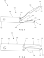
- the clip 102 includes a first arm 104 rigidly fixed to a distal end 110 of a capsule 108 and a second arm 106 slidably received within a longitudinal channel 112 of the capsule 108.
- the clip 102 is movable between an open configuration, in which a distal end 114 of the second arm 106 extends laterally away from and distally of a distal end 116 of the first arm 104, and a closed configuration, in which the distal end 114 of the second arm 106 extends toward the first arm 104 so that the distal end 114 of the second arm 106 is substantially longitudinally aligned with the distal end 116 of the first arm 104.
- the clip 102 is inserted to a target area of the living body and moved to the open configuration so that a first capture feature 118 of the first arm 104 captures a first portion of tissue along a first side of a tissue defect to be treated.
- the clip 102 With the first portion of tissue captured by the first arm 104, the clip 102 is moved toward a second side of the tissue defect so that a second capture feature 120 on the second arm 106 may capture a second portion of tissue along the second side of the tissue defect.
- the clip 102 may then be moved toward the closed configuration so that the first and second portions of tissue are moved toward one another to close the tissue defect. Since the clip 102 allows for approximation of the first and second sides of the tissue defect, the device 100 may be particularly suited to treat large tissue openings/defects.
- the capsule 108 extends longitudinally from a proximal end 122 to the distal end 110 and includes the channel 112 extending longitudinally therethrough.
- the proximal end 122 of the channel 112 is releasably coupled to a flexible member (not shown) of the proximal portion of the device 100 so that the clip 102, including the capsule 108, may be deployed therefrom to be implanted in the body.
- the capsule 108 is coupled to the flexible member via a bushing releasably coupled to the capsule 108 via cantilever arms of the bushing that are received within corresponding windows at the proximal end of the capsule 108, substantially as described in U.S. Patent Appln. Pub. No.
- the cantilever arms of the bushing may, for example, be biased to disengage from the capsule 108 but are held in position locked into the windows of the capsule by a support structure which is disengaged from the bushing arms when a control element connected to a proximal end of the second arm 106 is separated therefrom.
- the control element is coupled to the second arm 106 via a control member, as described in U.S. Patent Appln. Pub. No. 2014/0088616 or, in another embodiment, may be directly coupled to the second arm 106.
- the control element may be separated from the second arm 106 when the control element is drawn proximally relative to the capsule 108 to exceed a predetermined load.
- a locking tab of the second arm 106 moves radially outward to engage a portion of the capsule 108, thereby locking the clip 102 in the closed configuration.
- the first arm 104 extends distally from the distal end 110 of the capsule 108 to the distal end 116.
- the first arm 104 in this embodiment is integrally formed with the capsule 108.
- the first arm 104 may be rigidly fixed to the capsule 108 via any known connection mechanism such as, for example, welding.
- the first arm 104 extends from the distal end 110 of the capsule 108 along an axis substantially parallel to a longitudinal axis of the capsule 108.
- the first arm 104 extends from a proximal end 124 connected to the capsule 108 to the distal end 116.
- the distal end 116 may be curved or bent to include a distal tip 126 that extends laterally inward toward the longitudinal axis of the clip 102 so that the distal tip 126 may hook or grip target tissue received between the first and second arms 104, 106.
- the distal end 116 may also include the first capture feature 118 which may be configured as, for example, an undercut along a side of the first arm 104 facing the second arm 106.
- the first capture feature 118 may include a barb punched into the first arm 104 to extend toward the second arm 106.
- the first capture feature 118 may be configured as any of a variety of elements extending from a side or interior surface 128 of the first arm 104 to face toward the second arm 106.
- the interior surface of the first arm 104 may be cupped or curved so that longitudinal edges thereof are curved toward the second arm 106 forming a cupped pocket in which tissue may be received.
- a first arm 104' may have a broad (non-cupped) interior surface 128' which forms a tissue receiving pocket in one plane.
- the interior surface 128' may include teeth, spikes, grooves and/or a textured surface to provide additional gripping for tissue received between the first and second arms.
- a distal end 116' of the first arm 104' may also include a hook or other tissue piercing member such as a sharp point or barb for hooking or gripping tissue.
- a proximal end of the second arm 106 is slidably received within the channel 112 of the capsule 108 so that the second arm 106 is movable relative thereto between the open and closed configurations.
- the proximal end of the second arm 106 is connected to a control element extending proximally therefrom through the capsule 108 and the proximal portion of the device 100 to be controlled by a user.
- the control element is moved longitudinally relative to the device 100 to move the clip 102 between the open and closed configurations.
- the second arm 106 is formed of a compliant material which permits the second arm 106 to be moved between the open and closed configurations.
- the second arm 106 may be movable between the open and closed configuration via, for example, a living hinge.
- the second arm 106 may be biased toward the open configuration so that, when the second arm 106 is moved distally relative to the capsule 108, toward the open configuration, the second arm 106 reverts to the biased configuration and moves laterally away from the first arm 104 as the distal end 114 of the second arm 106 is moved distally past the distal end 116 of the first arm 104.
- the closed configuration the second arm 106 is drawn proximally into the channel 112 and restrained via an interior surface of the capsule 108 so that the second arm 106 is moved laterally toward the first arm 104 as the distal end 114 of the second arm 106 is moved toward the distal end 116 of the first arm 104.
- the distal ends 116, 114 of the first and second arms 104, 106, respectively may be substantially longitudinally aligned in the closed configuration.
- the distal end 114 of the second arm 106 may be bent or curved inward to form a distal tip 130 which extends laterally inward toward the longitudinal axis of the clip 102 so that the distal tip 130 hooks and/or grips tissue received between the first and second arms 104, 106.
- the distal tip 130 may include the second capture feature 120 for gripping tissue such as, for example, a sharp point or barb.
- the distal end 114 of the second arm 106 may include tissue gripping/capturing features such as an undercut and/or a barb, as described above in regard to the first arm 104, and as shown in Figs. 3 - 5 .
- the distal ends 116, 114 of the first and second arms 104, 106, respectively, are substantially longitudinally aligned in the closed configuration so that the distal tips 126, 130 are substantially aligned and face one another.
- a distal tip 130" of a second arm 106" includes a window 132" extending therethrough for accommodating a distal tip 126" of a first arm 104" therein.
- the distal tip 126" of the first arm 104" is received within the window 132" of the second arm 106", when gripping tissue.
- the second arm 106" may be permitted to be drawn proximally of the first arm 104" so that a distal end 114" of the second arm 106" may be drawn proximally past a distal end 116" of the first arm 104".
- an exemplary method utilizing the device 100 comprises inserting the clip 102, in the closed configuration, to a target area within a living body via, for example, a working channel of an endoscope.
- the clip 102 is able to approximate separated portions of tissue so that the clip 102 is particularly suited for treating large tissue defects.
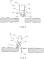
- the clip 102 is moved to the open configuration and manipulated so that the distal end 116 of the first arm 104 hooks or grips a first portion of tissue along a first side of the tissue defect, as shown in Fig. 7 .
- the first portion of tissue may be captured by the hook at the distal tip 126 of the first arm 104 and/or the first capture feature 118 which may include, for example, an undercut or barb.
- the clip 102 is moved toward a second portion of tissue along a second side of the tissue defect -- e.g., opposite the first side. Prior to moving the clip 102 toward the second portion of tissue, the clip 102 may be moved toward the closed configuration.
- the clip 102 upon reaching the second portion of tissue, the clip 102 is returned to the open configuration so that the second arm 106 is moved laterally and distally relative to the first arm 104 to hook and/or grip the second portion of tissue via the distal end 114 of the second arm 106, as shown in Fig. 8 .
- the second portion of tissue may be captured by the distal tip 13 0 and/or the second capture feature 120.
- the gripping features as described with respect to Figs. 10 and 11 , may be used to provide greater grippage of the first and second portions of tissue between the first and second arms 104, 106.
- the clip 102 is moved to the closed configuration to draw the second arm 106 toward the first arm 104.
- the second arm 106 is moved laterally toward the first arm 104 as the distal end 114 of the second arm 106 is moved toward the distal end 116 of the first arm 104, as shown in Fig. 9 , thereby drawing the first and second portions of tissue captured via the distal ends 116, 114, respectively, toward one another.
- tissue along the first and second sides of the tissue defect are drawn together to close the tissue defect.
- the clip 102 may be locked in the closed configuration and deployed to separate it from the proximal portion of the device 100, as would be understood by those skilled in the art.
- the control element connected to the proximal end of the second arm 106 may be drawn proximally relative to the capsule 108 until a predetermined threshold load is exceeded and the control element is separated from the second arm 106. Separation of the control element from the second arm 106 in this embodiment then allows a locking tab of the second arm 106 to engage the capsule 108, thereby locking the second arm 106 relative thereto, in the closed configuration.
- Proximal motion of the control element also facilitates release of the capsule 108 from the proximal portion of the device 100, thereby releasing the clip 102 so that it will remain in the body when the proximal portion of the device 100 is withdrawn from the body.
- the clip 102 will then be sloughed off as the natural healing process progresses as would be understood by those skilled in the art.
- the second arm 106 of the clip 102 may, for example, be formed of a compliant material such as, for example, Nitinol.
- the second arm 106 as shown in Fig. 12 , may be formed via a superelastic Nitinol forming process, which includes a die assembly 200, as shown in Figs. 13 - 15 , comprising a male die 202 and a female die 204 that are created to configure the Nitinol in the desired geometry.
- the die assembly 200 potentially increases the precision of the feature set in the Nitinol material and allows multiple sheets of metal to be formed at once, thereby decreasing cost and increasing volume output capabilities.
- the male and female dies 202, 204 are not required to be attached to any machinery such as, for example, a press. Rather, the male and female dies 202, 204 may include mating features such as, for example, bolts or pins, which allow the dies 202, 204 to be joined together while housing the Nitinol stock so that the Nitinol stock is configured to the desired geometry.
- the joined male and female dies 202, 204 with the configured Nitinol would then be placed in a fluidic bath set at approximately 500°C to treat the Nitinol.
- the Nitinol may be treated at a temperature of between 450 and 550 degrees C for from 2 to 20 minutes.
- the die assembly 200 is removed from the bath and immediately water quenched so that the Nitinol material retains its desired shape. Water quenching ensures that the Nitinol components are cooled immediately to room temperature, thereby limiting the amount of time in which the Nitinol components remain at high temperature. Ideally, the Nitinol components are cooled immediately after the Nitinol has reached 500°C. Thus, although the above method describes treating the Nitinol for approximately 10 minutes, this time may vary depending on the amount of time it takes to heat the Nitinol to 500°C.
- the die assembly 200 is created in 3D form so that complex geometry features may be created in the Nitinol.
- the female die 204 of the die assembly 200 includes a recess 206 sized and shaped to create the desired size and shape of the second arm 106.
- the recess 206 may include a curved portion 208 along a portion of a length thereof to create a corresponding radii 138 in the second arm 106, which biases the arm 106 toward the open configuration, as described above.
- the female die 204 may also include openings 210 for receiving mating features such as, for example, bolts or pins, for joining the male die 202 to the female die 204.
- the male die 202 may include a geometrically complementary protrusion 212 sized and shaped to be received within the recess 206 of the female die 204 so that when the male and female dies 202, 204 are mated or joined to one another, the Nitinol stock received within the recess 206 is molded to the desired size and shape of the second arm 106.
- the protrusion may include a first portion 214 sized and shaped to stamp out a shape 134 (e.g., rectangular) of a length of the second arm 106 and a second portion 216 protruding from the first portion 214 for adding a feature 136 (e.g., opening) in the second arm 106.
- the die assembly 200 may be designed to include multiple recesses 206 and protrusions 212 so that multiple arms 106 may be formed at a time, reducing cost while increasing volume output.
- the male and female dies 202, 204 are described as including particular design features, the male and female dies 202, 204 may include any of a variety of geometrical features designed to create a desired geometry of the second arm 106.
Landscapes
- Health & Medical Sciences (AREA)
- Life Sciences & Earth Sciences (AREA)
- Surgery (AREA)
- Chemical & Material Sciences (AREA)
- Engineering & Computer Science (AREA)
- General Health & Medical Sciences (AREA)
- Veterinary Medicine (AREA)
- Biomedical Technology (AREA)
- Heart & Thoracic Surgery (AREA)
- Medical Informatics (AREA)
- Molecular Biology (AREA)
- Animal Behavior & Ethology (AREA)
- Nuclear Medicine, Radiotherapy & Molecular Imaging (AREA)
- Public Health (AREA)
- Mechanical Engineering (AREA)
- Physics & Mathematics (AREA)
- Thermal Sciences (AREA)
- Crystallography & Structural Chemistry (AREA)
- Materials Engineering (AREA)
- Metallurgy (AREA)
- Organic Chemistry (AREA)
- Vascular Medicine (AREA)
- Reproductive Health (AREA)
- Ophthalmology & Optometry (AREA)
- Surgical Instruments (AREA)
Claims (12)
- Vorrichtung zur Behandlung eines Gewebes, die aufweist:eine Kapsel (108), die sich von einem proximalen Ende (122) zu einem distalen Ende (110) längs erstreckt und einen sich durch sie erstreckenden Kanal (112) aufweist, wobei die Kapsel (108) mit einem proximalen Abschnitt der Vorrichtung lösbar gekoppelt ist;einen ersten Arm (104), der am distalen Ende (110) der Kapsel (108) starr befestigt ist, um sich davon zu einem distalen Ende (116) distal zu erstrecken;einen zweiten Arm (106), der sich von einem proximalen Ende zu einem distalen Ende (114) erstreckt, wobei das proximale Ende im Kanal (112) der Kapsel (108) verschiebbar aufgenommen ist, so dass der zweite Arm (106) zwischen einer offenen Konfiguration und einer geschlossenen Konfiguration beweglich ist;eine Buchse, wobei die Kapsel (108) mit einem flexiblen Teil des proximalen Abschnitts der Vorrichtung über die Buchse gekoppelt ist, wobei die Buchse mit der Kapsel (108) über Kragarme der Buchse lösbar gekoppelt ist, die in entsprechenden Fenstern am proximalen Ende der Kapsel (108) aufgenommen sind; undein Steuerelement, das mit dem proximalen Ende des zweiten Arms (106) verbunden ist und sich davon durch die Kapsel (108) hindurch proximal erstreckt, wobei das Steuerelement so konfiguriert ist, dass es relativ zur Vorrichtung längs bewegt wird, um die Vorrichtung zwischen der offenen und geschlossenen Konfiguration zu bewegen;wobei das Steuerelement so konfiguriert ist, dass es die Vorrichtung in die offene Konfiguration bewegt, indem es den zweiten Arm (106) lateral weg vom ersten Arm (104) und das distale Ende des zweiten Arms (106) am distalen Ende des ersten Arms (104) vorbei distal bewegt;wobei das Steuerelement so konfiguriert ist, dass es die Vorrichtung in die geschlossene Konfiguration bewegt, indem es den zweiten Arm (106) hin zum ersten Arm (104) und das distale Ende des zweiten Arms (106) hin zum distalen Ende des ersten Arms (104) proximal bewegt; undwobei das Steuerelement mit dem proximalen Ende des zweiten Arms (106) lösbar gekoppelt ist, wobei das Steuerelement vom zweiten Arm (106) gelöst wird, um die Clipvorrichtung zu setzen.
- Vorrichtung nach Anspruch 1, wobei sich der erste Arm (104) entlang einer Achse erstreckt, die im Wesentlichen parallel zu einer Längsachse der Kapsel (108) ist.
- Vorrichtung nach Anspruch 1 oder 2, wobei das distale Ende des ersten Arms (104) ein Gewebeeinstechteil aufweist, das sich hin zum zweiten Arm (106) lateral nach innen erstreckt.
- Vorrichtung nach Anspruch 1 oder 2, wobei eine Innenfläche des ersten oder zweiten Arms (104, 106) einen Haken, eine Hinterschneidung oder einen Widerhaken zum Erfassen eines Zielgewebes aufweist.
- Vorrichtung nach einem der Ansprüche 1 bis 4, wobei der zweite Arm (106) hin zur offenen Konfiguration vorgespannt ist und über eine Innenfläche der Kapsel (108) in der geschlossenen Konfiguration festgehalten wird.
- Vorrichtung nach einem der Ansprüche 1 bis 5, wobei der zweite Arm (106) aus einem nachgiebigen Material gebildet ist.
- Vorrichtung nach Anspruch 6, wobei das nachgiebige Material Nitinol oder Edelstahl aufweist.
- Vorrichtung nach einem der Ansprüche 1 bis 7, wobei eine Innenfläche (128) des ersten Arms (104) gekrümmt ist, so dass sich Längskanten davon hin zum zweiten Arm (106) erstrecken, um eine muldenförmige Gewebeaufnahmetasche zu bilden.
- Vorrichtung nach einem der Ansprüche 1 bis 7, wobei der erste Arm (104) eine nicht muldenförmige Innenfläche (128') aufweist, die eine Gewebeaufnahmetasche in einer Ebene bildet.
- Vorrichtung nach Anspruch 9, wobei die Innenfläche (128') Zähne, Dorne, Rillen oder eine texturierte Oberfläche aufweist, um Gewebe zu ergreifen, das zwischen dem ersten und zweiten Arm (104, 106) aufgenommen ist.
- Vorrichtung nach einem der vorstehenden Ansprüche, wobei das Steuerelement so konfiguriert ist, dass es vom zweiten Arm (106) getrennt wird, wenn am Steuerelement relativ zur Kapsel (108) so proximal gezogen wird, dass eine vorbestimmte Last überschritten wird, und wobei die Trennung des Steuerelements vom zweiten Arm (106) ermöglicht, dass eine Verriegelungslasche des zweiten Arms (106) einen Eingriff mit der Kapsel (108) herstellt, wodurch der zweite Arm (106) relativ dazu in der geschlossenen Konfiguration verriegelt wird.
- Vorrichtung nach einem der Ansprüche 1 bis 10, wobei das Steuerelement so konfiguriert ist, dass es vom zweiten Arm (106) getrennt wird, wenn am Steuerelement relativ zur Kapsel (108) so proximal gezogen wird, dass eine vorbestimmte Last überschritten wird, und wobei sich bei Trennung des Steuerelements vom zweiten Arm (106) eine Verriegelungslasche des zweiten Arms (106) radial nach außen bewegt, um einen Eingriff mit einem Abschnitt der Kapsel (108) herzustellen, wodurch der Clip (102) in der geschlossenen Konfiguration verriegelt wird.
Priority Applications (2)
| Application Number | Priority Date | Filing Date | Title |
|---|---|---|---|
| EP23212076.6A EP4324410B1 (de) | 2016-05-09 | 2017-05-08 | Verschlussvorrichtung mit festbackenhaken |
| EP26158693.7A EP4732788A2 (de) | 2016-05-09 | 2017-05-08 | Verschlussvorrichtung mit festbackenhaken |
Applications Claiming Priority (2)
| Application Number | Priority Date | Filing Date | Title |
|---|---|---|---|
| US201662333615P | 2016-05-09 | 2016-05-09 | |
| PCT/US2017/031588 WO2017196745A1 (en) | 2016-05-09 | 2017-05-08 | Closure device with fixed jaw hook |
Related Child Applications (2)
| Application Number | Title | Priority Date | Filing Date |
|---|---|---|---|
| EP23212076.6A Division EP4324410B1 (de) | 2016-05-09 | 2017-05-08 | Verschlussvorrichtung mit festbackenhaken |
| EP26158693.7A Division EP4732788A2 (de) | 2016-05-09 | 2017-05-08 | Verschlussvorrichtung mit festbackenhaken |
Publications (2)
| Publication Number | Publication Date |
|---|---|
| EP3407805A1 EP3407805A1 (de) | 2018-12-05 |
| EP3407805B1 true EP3407805B1 (de) | 2023-11-29 |
Family
ID=58709658
Family Applications (3)
| Application Number | Title | Priority Date | Filing Date |
|---|---|---|---|
| EP17723918.3A Active EP3407805B1 (de) | 2016-05-09 | 2017-05-08 | Verschlussvorrichtung mit festbackenhaken |
| EP23212076.6A Active EP4324410B1 (de) | 2016-05-09 | 2017-05-08 | Verschlussvorrichtung mit festbackenhaken |
| EP26158693.7A Pending EP4732788A2 (de) | 2016-05-09 | 2017-05-08 | Verschlussvorrichtung mit festbackenhaken |
Family Applications After (2)
| Application Number | Title | Priority Date | Filing Date |
|---|---|---|---|
| EP23212076.6A Active EP4324410B1 (de) | 2016-05-09 | 2017-05-08 | Verschlussvorrichtung mit festbackenhaken |
| EP26158693.7A Pending EP4732788A2 (de) | 2016-05-09 | 2017-05-08 | Verschlussvorrichtung mit festbackenhaken |
Country Status (5)
| Country | Link |
|---|---|
| US (5) | US10537328B2 (de) |
| EP (3) | EP3407805B1 (de) |
| JP (2) | JP6620253B2 (de) |
| CN (2) | CN113693682B (de) |
| WO (1) | WO2017196745A1 (de) |
Families Citing this family (14)
| Publication number | Priority date | Publication date | Assignee | Title |
|---|---|---|---|---|
| EP3407805B1 (de) * | 2016-05-09 | 2023-11-29 | Boston Scientific Scimed, Inc. | Verschlussvorrichtung mit festbackenhaken |
| DE102018208555A1 (de) | 2018-05-30 | 2019-12-05 | Kardion Gmbh | Vorrichtung zum Verankern eines Herzunterstützungssystems in einem Blutgefäß, Verfahren zum Betreiben und Herstellverfahren zum Herstellen einer Vorrichtung und Herzunterstützungssystem |
| DE102018208537A1 (de) | 2018-05-30 | 2019-12-05 | Kardion Gmbh | Vorrichtung zum Anbinden eines Herzunterstützungssystems an eine Einführeinrichtung und Verfahren zum Herstellen einer Vorrichtung zum Anbinden eines Herzunterstützungssystems an eine Einführeinrichtung |
| DE102018208564A1 (de) | 2018-05-30 | 2019-12-05 | Kardion Gmbh | Steuerbare Einführungshülse |
| DE102018211297A1 (de) | 2018-07-09 | 2020-01-09 | Kardion Gmbh | Herzunterstützungssystem und Verfahren zur Überwachung der Integrität einer Haltestruktur eines Herzunterstützungssystems |
| CN112752547A (zh) * | 2018-09-24 | 2021-05-04 | 波士顿科学国际有限公司 | 具有改进的组织保持的侵略性特征的夹子 |
| JP2022088695A (ja) * | 2019-04-19 | 2022-06-15 | 有限会社Mizutec | 内視鏡クリップ |
| US20220096077A1 (en) * | 2020-09-28 | 2022-03-31 | Arch Day Design, Llc | Suture passing device |
| JP2023550938A (ja) | 2020-11-20 | 2023-12-06 | カルディオン ゲーエムベーハー | ガイドワイヤ補助具付き機械的循環支持システム |
| JP7668359B2 (ja) * | 2020-12-16 | 2025-04-24 | ボストン サイエンティフィック サイムド,インコーポレイテッド | 筋肉レベルにおける組織を把持するためのデバイスおよびシステム |
| CN113081121B (zh) * | 2021-04-25 | 2025-11-07 | 上海交通大学医学院附属第九人民医院 | 一种组织缝合夹和组织的缝合方法 |
| KR20240006062A (ko) | 2021-05-07 | 2024-01-12 | 텔리플렉스 메디컬 인코포레이티드 | 외과용 클립을 언래칭하기 위한 장치 및 방법 |
| CN117653234A (zh) * | 2024-01-10 | 2024-03-08 | 江苏华质医学科技有限公司 | 一种内窥镜孔道组织单臂缝合夹及操作方法 |
| CN120753770B (zh) * | 2025-08-11 | 2026-03-27 | 上海汇禾医疗科技股份有限公司 | 一种多功能异物抓捕装置及其操作方法 |
Citations (1)
| Publication number | Priority date | Publication date | Assignee | Title |
|---|---|---|---|---|
| EP3305215A1 (de) * | 2015-05-27 | 2018-04-11 | Olympus Corporation | Verfahren für ein endoskop |
Family Cites Families (33)
| Publication number | Priority date | Publication date | Assignee | Title |
|---|---|---|---|---|
| US3882854A (en) * | 1973-08-23 | 1975-05-13 | Research Corp | Surgical clip and applicator |
| JPS5320957Y2 (de) * | 1973-11-14 | 1978-06-01 | ||
| US4446865A (en) * | 1981-03-16 | 1984-05-08 | Ethicon, Inc. | Plastic ligating clips |
| US5241968A (en) * | 1990-05-10 | 1993-09-07 | Symbiosis Corporation | Single acting endoscopic instruments |
| US5304183A (en) * | 1992-03-23 | 1994-04-19 | Laparomed Corporation | Tethered clamp retractor |
| US5681330A (en) * | 1994-03-02 | 1997-10-28 | Ethicon Endo-Surgery, Inc. | Sterile occlusion fasteners and instrument and method for their placement |
| DE4415521C2 (de) * | 1994-05-04 | 2003-01-30 | Storz Reling Sybill Gesamthand | Instrument zum Einsatz bei endoskopischen Eingriffen |
| US5569299A (en) * | 1995-03-01 | 1996-10-29 | Symbiosis Corporation | Endoscopic urological biopsy forceps |
| US5843244A (en) * | 1996-06-13 | 1998-12-01 | Nitinol Devices And Components | Shape memory alloy treatment |
| US6106642A (en) * | 1998-02-19 | 2000-08-22 | Boston Scientific Limited | Process for the improved ductility of nitinol |
| JP2000210294A (ja) * | 1998-11-20 | 2000-08-02 | Asahi Optical Co Ltd | 内視鏡用生検鉗子 |
| US7094245B2 (en) * | 2001-10-05 | 2006-08-22 | Scimed Life Systems, Inc. | Device and method for through the scope endoscopic hemostatic clipping |
| US7131977B2 (en) * | 2002-08-27 | 2006-11-07 | Pilling Weck Incorporated | Apparatus and method for removing a clip |
| EP3878381A3 (de) | 2003-09-30 | 2021-11-10 | Boston Scientific Scimed, Inc. | Endoskop-spannungsglied-freigabeklemme |
| US7494461B2 (en) * | 2003-09-30 | 2009-02-24 | Boston Scientific Scimed, Inc. | Through the scope tension member release clip |
| JP2008514244A (ja) | 2004-09-07 | 2008-05-08 | ビンモエラー,ケネス | 独立して作動する脚部を有する内視鏡装置 |
| US20080312686A1 (en) * | 2005-07-01 | 2008-12-18 | Abbott Laboratories | Antimicrobial closure element and closure element applier |
| US8136888B2 (en) * | 2005-12-14 | 2012-03-20 | Olympus Medical Systems Corp. | Lifting method for lesion area, and anchoring device |
| US7648514B1 (en) * | 2006-03-08 | 2010-01-19 | Granit Medical Innovation, Llc | Deep endoscopic staple and stapler |
| JP5297816B2 (ja) * | 2007-01-26 | 2013-09-25 | オリンパスメディカルシステムズ株式会社 | 把持装置 |
| US8979872B2 (en) * | 2007-03-13 | 2015-03-17 | Longevity Surgical, Inc. | Devices for engaging, approximating and fastening tissue |
| WO2009120953A2 (en) * | 2008-03-27 | 2009-10-01 | Mayo Foundation For Medical Education And Research | Navigation and tissue capture systems and methods |
| JP2010125200A (ja) * | 2008-11-28 | 2010-06-10 | Mizutec:Kk | 医療用把持装置 |
| WO2011037817A2 (en) | 2009-09-25 | 2011-03-31 | Boston Scientific Scimed, Inc. | Devices for approximating tissue and related methods of use |
| US8734469B2 (en) * | 2009-10-13 | 2014-05-27 | Covidien Lp | Suture clip applier |
| CA2780156A1 (en) * | 2009-11-09 | 2011-05-12 | Entourage Medical Technologies, Inc. | System and method for providing access and closure to tissue |
| WO2013067662A1 (zh) * | 2011-11-11 | 2013-05-16 | Zhu Jian | 一种夹持或结扎装置 |
| JP2013244054A (ja) * | 2012-05-23 | 2013-12-09 | Piolax Medical Device:Kk | 医療用把持具 |
| JP2015532859A (ja) | 2012-09-24 | 2015-11-16 | ボストン サイエンティフィック サイムド,インコーポレイテッドBoston Scientific Scimed,Inc. | 止血クリップのための解法機構 |
| DE102013101874A1 (de) * | 2013-02-26 | 2014-09-11 | Karl Storz Gmbh & Co. Kg | Medizinisches Instrument mit einem korkenzieherartigen Verbindungselement |
| US9554818B2 (en) * | 2013-02-27 | 2017-01-31 | Mohammadreza Rohaninejad | Methods and systems for magnetically suspending tissue structures |
| GB201421669D0 (en) * | 2014-12-05 | 2015-01-21 | Rolls Royce Plc | A forging apparatus |
| EP3407805B1 (de) * | 2016-05-09 | 2023-11-29 | Boston Scientific Scimed, Inc. | Verschlussvorrichtung mit festbackenhaken |
-
2017
- 2017-05-08 EP EP17723918.3A patent/EP3407805B1/de active Active
- 2017-05-08 CN CN202111061499.3A patent/CN113693682B/zh active Active
- 2017-05-08 EP EP23212076.6A patent/EP4324410B1/de active Active
- 2017-05-08 EP EP26158693.7A patent/EP4732788A2/de active Pending
- 2017-05-08 JP JP2018563774A patent/JP6620253B2/ja active Active
- 2017-05-08 CN CN201780028592.XA patent/CN109152576B/zh active Active
- 2017-05-08 WO PCT/US2017/031588 patent/WO2017196745A1/en not_active Ceased
- 2017-05-08 US US15/589,620 patent/US10537328B2/en active Active
-
2019
- 2019-11-21 JP JP2019210458A patent/JP6850856B2/ja active Active
- 2019-12-06 US US16/706,237 patent/US11344305B2/en active Active
-
2022
- 2022-04-26 US US17/660,793 patent/US11918219B2/en active Active
- 2022-12-08 US US18/063,562 patent/US11992217B2/en active Active
-
2024
- 2024-04-25 US US18/646,111 patent/US12521114B2/en active Active
Patent Citations (1)
| Publication number | Priority date | Publication date | Assignee | Title |
|---|---|---|---|---|
| EP3305215A1 (de) * | 2015-05-27 | 2018-04-11 | Olympus Corporation | Verfahren für ein endoskop |
Also Published As
| Publication number | Publication date |
|---|---|
| EP4732788A2 (de) | 2026-04-29 |
| EP3407805A1 (de) | 2018-12-05 |
| US20200107831A1 (en) | 2020-04-09 |
| CN113693682A (zh) | 2021-11-26 |
| US11992217B2 (en) | 2024-05-28 |
| US20220249093A1 (en) | 2022-08-11 |
| US11918219B2 (en) | 2024-03-05 |
| EP4324410B1 (de) | 2026-03-04 |
| JP6850856B2 (ja) | 2021-03-31 |
| WO2017196745A1 (en) | 2017-11-16 |
| US20170319208A1 (en) | 2017-11-09 |
| CN113693682B (zh) | 2024-09-13 |
| JP2019508203A (ja) | 2019-03-28 |
| US12521114B2 (en) | 2026-01-13 |
| US20240277338A1 (en) | 2024-08-22 |
| US10537328B2 (en) | 2020-01-21 |
| EP4324410A3 (de) | 2024-04-17 |
| JP2020049225A (ja) | 2020-04-02 |
| US11344305B2 (en) | 2022-05-31 |
| US20230121076A1 (en) | 2023-04-20 |
| CN109152576B (zh) | 2021-09-28 |
| CN109152576A (zh) | 2019-01-04 |
| JP6620253B2 (ja) | 2019-12-11 |
| EP4324410A2 (de) | 2024-02-21 |
Similar Documents
| Publication | Publication Date | Title |
|---|---|---|
| US12521114B2 (en) | Closure device with fixed jaw hook | |
| US12310589B2 (en) | Devices for approximating tissue and related methods of use | |
| JP7477548B2 (ja) | 止血クリップ | |
| JP6694975B2 (ja) | 組織を治療するためのシステム | |
| EP3019093B1 (de) | Klemmvorrichtung zum greifen von geweben und zum schliessen einer wunde | |
| EP3906865A1 (de) | Breiter hämostaseclip |
Legal Events
| Date | Code | Title | Description |
|---|---|---|---|
| STAA | Information on the status of an ep patent application or granted ep patent |
Free format text: STATUS: UNKNOWN |
|
| STAA | Information on the status of an ep patent application or granted ep patent |
Free format text: STATUS: THE INTERNATIONAL PUBLICATION HAS BEEN MADE |
|
| PUAI | Public reference made under article 153(3) epc to a published international application that has entered the european phase |
Free format text: ORIGINAL CODE: 0009012 |
|
| STAA | Information on the status of an ep patent application or granted ep patent |
Free format text: STATUS: REQUEST FOR EXAMINATION WAS MADE |
|
| 17P | Request for examination filed |
Effective date: 20180829 |
|
| AK | Designated contracting states |
Kind code of ref document: A1 Designated state(s): AL AT BE BG CH CY CZ DE DK EE ES FI FR GB GR HR HU IE IS IT LI LT LU LV MC MK MT NL NO PL PT RO RS SE SI SK SM TR |
|
| AX | Request for extension of the european patent |
Extension state: BA ME |
|
| DAV | Request for validation of the european patent (deleted) | ||
| DAX | Request for extension of the european patent (deleted) | ||
| STAA | Information on the status of an ep patent application or granted ep patent |
Free format text: STATUS: EXAMINATION IS IN PROGRESS |
|
| 17Q | First examination report despatched |
Effective date: 20200211 |
|
| GRAP | Despatch of communication of intention to grant a patent |
Free format text: ORIGINAL CODE: EPIDOSNIGR1 |
|
| STAA | Information on the status of an ep patent application or granted ep patent |
Free format text: STATUS: GRANT OF PATENT IS INTENDED |
|
| INTG | Intention to grant announced |
Effective date: 20230713 |
|
| GRAS | Grant fee paid |
Free format text: ORIGINAL CODE: EPIDOSNIGR3 |
|
| GRAA | (expected) grant |
Free format text: ORIGINAL CODE: 0009210 |
|
| STAA | Information on the status of an ep patent application or granted ep patent |
Free format text: STATUS: THE PATENT HAS BEEN GRANTED |
|
| AK | Designated contracting states |
Kind code of ref document: B1 Designated state(s): AL AT BE BG CH CY CZ DE DK EE ES FI FR GB GR HR HU IE IS IT LI LT LU LV MC MK MT NL NO PL PT RO RS SE SI SK SM TR |
|
| REG | Reference to a national code |
Ref country code: GB Ref legal event code: FG4D |
|
| REG | Reference to a national code |
Ref country code: CH Ref legal event code: EP |
|
| REG | Reference to a national code |
Ref country code: DE Ref legal event code: R096 Ref document number: 602017076956 Country of ref document: DE |
|
| REG | Reference to a national code |
Ref country code: IE Ref legal event code: FG4D |
|
| REG | Reference to a national code |
Ref country code: NL Ref legal event code: FP |
|
| REG | Reference to a national code |
Ref country code: LT Ref legal event code: MG9D |
|
| PG25 | Lapsed in a contracting state [announced via postgrant information from national office to epo] |
Ref country code: GR Free format text: LAPSE BECAUSE OF FAILURE TO SUBMIT A TRANSLATION OF THE DESCRIPTION OR TO PAY THE FEE WITHIN THE PRESCRIBED TIME-LIMIT Effective date: 20240301 |
|
| PG25 | Lapsed in a contracting state [announced via postgrant information from national office to epo] |
Ref country code: IS Free format text: LAPSE BECAUSE OF FAILURE TO SUBMIT A TRANSLATION OF THE DESCRIPTION OR TO PAY THE FEE WITHIN THE PRESCRIBED TIME-LIMIT Effective date: 20240329 |
|
| PG25 | Lapsed in a contracting state [announced via postgrant information from national office to epo] |
Ref country code: LT Free format text: LAPSE BECAUSE OF FAILURE TO SUBMIT A TRANSLATION OF THE DESCRIPTION OR TO PAY THE FEE WITHIN THE PRESCRIBED TIME-LIMIT Effective date: 20231129 |
|
| PG25 | Lapsed in a contracting state [announced via postgrant information from national office to epo] |
Ref country code: ES Free format text: LAPSE BECAUSE OF FAILURE TO SUBMIT A TRANSLATION OF THE DESCRIPTION OR TO PAY THE FEE WITHIN THE PRESCRIBED TIME-LIMIT Effective date: 20231129 |
|
| PG25 | Lapsed in a contracting state [announced via postgrant information from national office to epo] |
Ref country code: LT Free format text: LAPSE BECAUSE OF FAILURE TO SUBMIT A TRANSLATION OF THE DESCRIPTION OR TO PAY THE FEE WITHIN THE PRESCRIBED TIME-LIMIT Effective date: 20231129 Ref country code: IS Free format text: LAPSE BECAUSE OF FAILURE TO SUBMIT A TRANSLATION OF THE DESCRIPTION OR TO PAY THE FEE WITHIN THE PRESCRIBED TIME-LIMIT Effective date: 20240329 Ref country code: GR Free format text: LAPSE BECAUSE OF FAILURE TO SUBMIT A TRANSLATION OF THE DESCRIPTION OR TO PAY THE FEE WITHIN THE PRESCRIBED TIME-LIMIT Effective date: 20240301 Ref country code: ES Free format text: LAPSE BECAUSE OF FAILURE TO SUBMIT A TRANSLATION OF THE DESCRIPTION OR TO PAY THE FEE WITHIN THE PRESCRIBED TIME-LIMIT Effective date: 20231129 Ref country code: BG Free format text: LAPSE BECAUSE OF FAILURE TO SUBMIT A TRANSLATION OF THE DESCRIPTION OR TO PAY THE FEE WITHIN THE PRESCRIBED TIME-LIMIT Effective date: 20240229 |
|
| REG | Reference to a national code |
Ref country code: AT Ref legal event code: MK05 Ref document number: 1635280 Country of ref document: AT Kind code of ref document: T Effective date: 20231129 |
|
| PG25 | Lapsed in a contracting state [announced via postgrant information from national office to epo] |
Ref country code: SE Free format text: LAPSE BECAUSE OF FAILURE TO SUBMIT A TRANSLATION OF THE DESCRIPTION OR TO PAY THE FEE WITHIN THE PRESCRIBED TIME-LIMIT Effective date: 20231129 Ref country code: RS Free format text: LAPSE BECAUSE OF FAILURE TO SUBMIT A TRANSLATION OF THE DESCRIPTION OR TO PAY THE FEE WITHIN THE PRESCRIBED TIME-LIMIT Effective date: 20231129 Ref country code: PL Free format text: LAPSE BECAUSE OF FAILURE TO SUBMIT A TRANSLATION OF THE DESCRIPTION OR TO PAY THE FEE WITHIN THE PRESCRIBED TIME-LIMIT Effective date: 20231129 Ref country code: NO Free format text: LAPSE BECAUSE OF FAILURE TO SUBMIT A TRANSLATION OF THE DESCRIPTION OR TO PAY THE FEE WITHIN THE PRESCRIBED TIME-LIMIT Effective date: 20240229 Ref country code: LV Free format text: LAPSE BECAUSE OF FAILURE TO SUBMIT A TRANSLATION OF THE DESCRIPTION OR TO PAY THE FEE WITHIN THE PRESCRIBED TIME-LIMIT Effective date: 20231129 Ref country code: HR Free format text: LAPSE BECAUSE OF FAILURE TO SUBMIT A TRANSLATION OF THE DESCRIPTION OR TO PAY THE FEE WITHIN THE PRESCRIBED TIME-LIMIT Effective date: 20231129 |
|
| PG25 | Lapsed in a contracting state [announced via postgrant information from national office to epo] |
Ref country code: DK Free format text: LAPSE BECAUSE OF FAILURE TO SUBMIT A TRANSLATION OF THE DESCRIPTION OR TO PAY THE FEE WITHIN THE PRESCRIBED TIME-LIMIT Effective date: 20231129 |
|
| PG25 | Lapsed in a contracting state [announced via postgrant information from national office to epo] |
Ref country code: AT Free format text: LAPSE BECAUSE OF FAILURE TO SUBMIT A TRANSLATION OF THE DESCRIPTION OR TO PAY THE FEE WITHIN THE PRESCRIBED TIME-LIMIT Effective date: 20231129 Ref country code: CZ Free format text: LAPSE BECAUSE OF FAILURE TO SUBMIT A TRANSLATION OF THE DESCRIPTION OR TO PAY THE FEE WITHIN THE PRESCRIBED TIME-LIMIT Effective date: 20231129 |
|
| PG25 | Lapsed in a contracting state [announced via postgrant information from national office to epo] |
Ref country code: SK Free format text: LAPSE BECAUSE OF FAILURE TO SUBMIT A TRANSLATION OF THE DESCRIPTION OR TO PAY THE FEE WITHIN THE PRESCRIBED TIME-LIMIT Effective date: 20231129 |
|
| PG25 | Lapsed in a contracting state [announced via postgrant information from national office to epo] |
Ref country code: SM Free format text: LAPSE BECAUSE OF FAILURE TO SUBMIT A TRANSLATION OF THE DESCRIPTION OR TO PAY THE FEE WITHIN THE PRESCRIBED TIME-LIMIT Effective date: 20231129 Ref country code: SK Free format text: LAPSE BECAUSE OF FAILURE TO SUBMIT A TRANSLATION OF THE DESCRIPTION OR TO PAY THE FEE WITHIN THE PRESCRIBED TIME-LIMIT Effective date: 20231129 Ref country code: RO Free format text: LAPSE BECAUSE OF FAILURE TO SUBMIT A TRANSLATION OF THE DESCRIPTION OR TO PAY THE FEE WITHIN THE PRESCRIBED TIME-LIMIT Effective date: 20231129 Ref country code: IT Free format text: LAPSE BECAUSE OF FAILURE TO SUBMIT A TRANSLATION OF THE DESCRIPTION OR TO PAY THE FEE WITHIN THE PRESCRIBED TIME-LIMIT Effective date: 20231129 Ref country code: EE Free format text: LAPSE BECAUSE OF FAILURE TO SUBMIT A TRANSLATION OF THE DESCRIPTION OR TO PAY THE FEE WITHIN THE PRESCRIBED TIME-LIMIT Effective date: 20231129 Ref country code: DK Free format text: LAPSE BECAUSE OF FAILURE TO SUBMIT A TRANSLATION OF THE DESCRIPTION OR TO PAY THE FEE WITHIN THE PRESCRIBED TIME-LIMIT Effective date: 20231129 Ref country code: CZ Free format text: LAPSE BECAUSE OF FAILURE TO SUBMIT A TRANSLATION OF THE DESCRIPTION OR TO PAY THE FEE WITHIN THE PRESCRIBED TIME-LIMIT Effective date: 20231129 Ref country code: AT Free format text: LAPSE BECAUSE OF FAILURE TO SUBMIT A TRANSLATION OF THE DESCRIPTION OR TO PAY THE FEE WITHIN THE PRESCRIBED TIME-LIMIT Effective date: 20231129 |
|
| PG25 | Lapsed in a contracting state [announced via postgrant information from national office to epo] |
Ref country code: PT Free format text: LAPSE BECAUSE OF FAILURE TO SUBMIT A TRANSLATION OF THE DESCRIPTION OR TO PAY THE FEE WITHIN THE PRESCRIBED TIME-LIMIT Effective date: 20240401 |
|
| PG25 | Lapsed in a contracting state [announced via postgrant information from national office to epo] |
Ref country code: PT Free format text: LAPSE BECAUSE OF FAILURE TO SUBMIT A TRANSLATION OF THE DESCRIPTION OR TO PAY THE FEE WITHIN THE PRESCRIBED TIME-LIMIT Effective date: 20240401 |
|
| REG | Reference to a national code |
Ref country code: DE Ref legal event code: R097 Ref document number: 602017076956 Country of ref document: DE |
|
| PLBE | No opposition filed within time limit |
Free format text: ORIGINAL CODE: 0009261 |
|
| STAA | Information on the status of an ep patent application or granted ep patent |
Free format text: STATUS: NO OPPOSITION FILED WITHIN TIME LIMIT |
|
| PG25 | Lapsed in a contracting state [announced via postgrant information from national office to epo] |
Ref country code: SI Free format text: LAPSE BECAUSE OF FAILURE TO SUBMIT A TRANSLATION OF THE DESCRIPTION OR TO PAY THE FEE WITHIN THE PRESCRIBED TIME-LIMIT Effective date: 20231129 |
|
| PG25 | Lapsed in a contracting state [announced via postgrant information from national office to epo] |
Ref country code: SI Free format text: LAPSE BECAUSE OF FAILURE TO SUBMIT A TRANSLATION OF THE DESCRIPTION OR TO PAY THE FEE WITHIN THE PRESCRIBED TIME-LIMIT Effective date: 20231129 |
|
| 26N | No opposition filed |
Effective date: 20240830 |
|
| REG | Reference to a national code |
Ref country code: CH Ref legal event code: PL |
|
| PG25 | Lapsed in a contracting state [announced via postgrant information from national office to epo] |
Ref country code: MC Free format text: LAPSE BECAUSE OF FAILURE TO SUBMIT A TRANSLATION OF THE DESCRIPTION OR TO PAY THE FEE WITHIN THE PRESCRIBED TIME-LIMIT Effective date: 20231129 |
|
| PG25 | Lapsed in a contracting state [announced via postgrant information from national office to epo] |
Ref country code: LU Free format text: LAPSE BECAUSE OF NON-PAYMENT OF DUE FEES Effective date: 20240508 |
|
| PG25 | Lapsed in a contracting state [announced via postgrant information from national office to epo] |
Ref country code: MC Free format text: LAPSE BECAUSE OF FAILURE TO SUBMIT A TRANSLATION OF THE DESCRIPTION OR TO PAY THE FEE WITHIN THE PRESCRIBED TIME-LIMIT Effective date: 20231129 Ref country code: LU Free format text: LAPSE BECAUSE OF NON-PAYMENT OF DUE FEES Effective date: 20240508 Ref country code: CH Free format text: LAPSE BECAUSE OF NON-PAYMENT OF DUE FEES Effective date: 20240531 |
|
| REG | Reference to a national code |
Ref country code: BE Ref legal event code: MM Effective date: 20240531 |
|
| PG25 | Lapsed in a contracting state [announced via postgrant information from national office to epo] |
Ref country code: BE Free format text: LAPSE BECAUSE OF NON-PAYMENT OF DUE FEES Effective date: 20240531 |
|
| PG25 | Lapsed in a contracting state [announced via postgrant information from national office to epo] |
Ref country code: FR Free format text: LAPSE BECAUSE OF NON-PAYMENT OF DUE FEES Effective date: 20240531 |
|
| PGFP | Annual fee paid to national office [announced via postgrant information from national office to epo] |
Ref country code: NL Payment date: 20250423 Year of fee payment: 9 |
|
| PGFP | Annual fee paid to national office [announced via postgrant information from national office to epo] |
Ref country code: DE Payment date: 20250423 Year of fee payment: 9 |
|
| PGFP | Annual fee paid to national office [announced via postgrant information from national office to epo] |
Ref country code: IE Payment date: 20250424 Year of fee payment: 9 |
|
| PG25 | Lapsed in a contracting state [announced via postgrant information from national office to epo] |
Ref country code: CY Free format text: LAPSE BECAUSE OF FAILURE TO SUBMIT A TRANSLATION OF THE DESCRIPTION OR TO PAY THE FEE WITHIN THE PRESCRIBED TIME-LIMIT; INVALID AB INITIO Effective date: 20170508 |
|
| PG25 | Lapsed in a contracting state [announced via postgrant information from national office to epo] |
Ref country code: HU Free format text: LAPSE BECAUSE OF FAILURE TO SUBMIT A TRANSLATION OF THE DESCRIPTION OR TO PAY THE FEE WITHIN THE PRESCRIBED TIME-LIMIT; INVALID AB INITIO Effective date: 20170508 |
|
| PG25 | Lapsed in a contracting state [announced via postgrant information from national office to epo] |
Ref country code: FI Free format text: LAPSE BECAUSE OF FAILURE TO SUBMIT A TRANSLATION OF THE DESCRIPTION OR TO PAY THE FEE WITHIN THE PRESCRIBED TIME-LIMIT Effective date: 20231129 |
|
| PGFP | Annual fee paid to national office [announced via postgrant information from national office to epo] |
Ref country code: GB Payment date: 20260317 Year of fee payment: 10 |