EP3407842B1 - Orthèse de réclinaison à sangles de traction - Google Patents
Orthèse de réclinaison à sangles de traction Download PDFInfo
- Publication number
- EP3407842B1 EP3407842B1 EP17702826.3A EP17702826A EP3407842B1 EP 3407842 B1 EP3407842 B1 EP 3407842B1 EP 17702826 A EP17702826 A EP 17702826A EP 3407842 B1 EP3407842 B1 EP 3407842B1
- Authority
- EP
- European Patent Office
- Prior art keywords
- reclination
- straps
- splint
- section
- strap
- Prior art date
- Legal status (The legal status is an assumption and is not a legal conclusion. Google has not performed a legal analysis and makes no representation as to the accuracy of the status listed.)
- Active
Links
Images



Classifications
-
- A—HUMAN NECESSITIES
- A61—MEDICAL OR VETERINARY SCIENCE; HYGIENE
- A61F—FILTERS IMPLANTABLE INTO BLOOD VESSELS; PROSTHESES; DEVICES PROVIDING PATENCY TO, OR PREVENTING COLLAPSING OF, TUBULAR STRUCTURES OF THE BODY, e.g. STENTS; ORTHOPAEDIC, NURSING OR CONTRACEPTIVE DEVICES; FOMENTATION; TREATMENT OR PROTECTION OF EYES OR EARS; BANDAGES, DRESSINGS OR ABSORBENT PADS; FIRST-AID KITS
- A61F5/00—Orthopaedic methods or devices for non-surgical treatment of bones or joints; Nursing devices ; Anti-rape devices
- A61F5/01—Orthopaedic devices, e.g. long-term immobilising or pressure directing devices for treating broken or deformed bones such as splints, casts or braces
- A61F5/02—Orthopaedic corsets
- A61F5/026—Back straightening devices with shoulder braces to force back the shoulder to obtain a correct curvature of the spine
-
- A—HUMAN NECESSITIES
- A61—MEDICAL OR VETERINARY SCIENCE; HYGIENE
- A61F—FILTERS IMPLANTABLE INTO BLOOD VESSELS; PROSTHESES; DEVICES PROVIDING PATENCY TO, OR PREVENTING COLLAPSING OF, TUBULAR STRUCTURES OF THE BODY, e.g. STENTS; ORTHOPAEDIC, NURSING OR CONTRACEPTIVE DEVICES; FOMENTATION; TREATMENT OR PROTECTION OF EYES OR EARS; BANDAGES, DRESSINGS OR ABSORBENT PADS; FIRST-AID KITS
- A61F5/00—Orthopaedic methods or devices for non-surgical treatment of bones or joints; Nursing devices ; Anti-rape devices
- A61F5/01—Orthopaedic devices, e.g. long-term immobilising or pressure directing devices for treating broken or deformed bones such as splints, casts or braces
- A61F5/02—Orthopaedic corsets
- A61F5/028—Braces for providing support to the lower back, e.g. lumbo sacral supports
Definitions
- the invention relates to a back orthosis for the treatment and straightening of a curved spine or for the treatment and correction of postural defects, particularly in the upper back area, by repositioning the shoulders.
- a new type of reclining orthosis with a special belt guide is provided, which is highly effective in its function and is easy to put on and adjust.
- Reclining orthoses also called erection orthoses, essentially consist of a rigid stiffening element that runs along the spine ("recliner"), which is pressed against the spine by means of belts and bandages that grip the patient's torso under tension to convey the support effect.
- Known reclining orthoses grip the shoulders with two shoulder straps and pull the shoulders back when worn.
- the patient's spine is mechanically stabilized by the interaction of the shoulder straps, the recliner and the bandage that surrounds the trunk and, above all, is raised in the area of the shoulder, the upper thoracic spine. The more the shoulder straps are tightened, the more the shoulders are pulled back, causing the upper body to straighten up.
- a disadvantage of known reclination orthoses is also the complex structure and rigid design of the bandages and tension belts, which are designed purely to achieve a specific support effect, but do not adapt individually to the specific indication situation, the therapy requirement and / or the anatomical conditions allow enough.
- the support effect is absent, particularly when the patient is moving, because known reclination orthoses cannot adequately follow the movement.
- known reclining orthoses are often difficult to put on by the patient, since the mechanical force then required for the erection and support action, in particular tensile force, tension force, cannot be applied sufficiently by the patient himself. This is particularly difficult in the elderly.
- the present invention was based on the technical problem of providing an improved reclination orthosis which can impart a support effect over the entire length of the spine to the pelvis, is specifically adaptable and can be easily and effectively applied by the patient himself.
- the technical problem is completely solved by a reclining orthosis according to the claims, in particular a reclining orthosis with a rigid recliner splint that runs along the entire spine in the applied state, a lap belt that sits in particular on the pelvic crest and pelvis and can be tensioned around the pelvis, and two solitary, especially free-running , stretchable shoulder straps.
- the reclination orthosis according to the invention preferably consists exclusively of these supporting force-introducing elements without further bandages and belt elements, apart from dependent passive auxiliary applications such as upholstery, pads and belt guides and fastening systems.
- the belts of the reclination orthosis according to the invention have a very special and novel belt guide around the patient's body with at least three specific belt crossings.
- both belts are in each case starting from a caudal, particularly low-lying section of the recliner splint. From there they run cranially, "above”, along the ipsilateral body flank along the patient's chest, i.e. under the armpit, over the respective ipsilateral front shoulder, where they form shoulder strap sections, then back dorsally on a cranial Section of this recliner rail past, where they are guided freely in guides, caudally, "below".
- the straps intersect at a central dorsal cranial crossing point and continue caudally after each contralateral, namely on the contralateral body flank on the patient's chest, i.e. under the armpit, pulling along ventrally.
- the contralateral belt is in a lateral thoracic crossing point, which is preferably located between the armpit and the iliac crest, crossing with the ipsilateral ascending belt partner.
- the contralateral belts each run out ventrally into belt ends, which can be fixed directly under tension to the ventral section of the lap belt of the orthosis.
- the reclination orthosis according to the invention is therefore first put on in the manner of a backpack with two solitary shoulder straps and is tensioned to the body on the pelvis by means of a lap belt which is firmly connected to the recliner splint.
- the free strap ends of the individual straps attached to the caudal section of the recliner splint can be individually pulled and tensioned, the tensile force being due to the free-running straps in particular to important pressure introduction points of the orthosis, namely: front shoulder / clavicle - cranial section of the recliner splint - caudal section the recliner splint - lap belt can automatically distribute and so a self-contained traction circuit can be formed.
- the straps form shoulder strap sections at which the straps are mainly introduced into the body.
- the shoulders can be pulled backwards according to the therapy and the recliner splint can be pulled to the spine at the same time, thus straightening the upper thoracic and cervical spine.
- the supportive action of the recliner also extends to the lower thoracic spine, the lumbar spine and the sacrum.
- a new freedom of movement of the patient is advantageously made possible by the, in particular, free belt guidance of the two body-encircling shoulder straps, which are fixed or can only be fixed on the caudal section of the recliner splint on the one hand and on the ventral section of the lap belt on the other.
- the orthosis sits in a stable position on the body and always adapts dynamically to the movement phases thanks to the closed circuit.
- a dynamic distribution of force at the pressure introduction points, depending on the state of movement and posture of the patient, is particularly advantageously realized, which ensures the support effect and reclination in every movement phase and at the same time increases the comfort for the patient.
- This dynamic distribution of force during movement enables the patient to actively adopt an upright posture and to support the supportive effect of his reclining orthosis through active muscle activity, consciously and partially reflexively.
- the novel belt routing provides additional, particularly solitary pressure introduction points in the area of the pelvic socket, in the area of the anterior iliac crest and in particular also on the two thoracic lateral belt crossings on the sides of the chest, which can also contribute to a reflex activation of the holding muscles.
- the feared disadvantage of known static support orthoses namely the weakening of the holding muscles, is not only avoided in the reclination orthosis according to the invention with dynamic force distribution and pressure introduction; rather, a training effect for the holding muscles is achieved. This is particularly useful in rehabilitation, for example after accidents or other types of spinal injuries, for example after surgery.
- the reclination orthosis according to the invention achieves these advantages with a simple mechanical structure and a small number of specific components.
- the anchoring points of the two shoulder straps on the recliner rail are in the area of the caudal section of the Freely selectable recliner track.
- several anchoring points are provided, where anchor eyelets, through which the belts are each guided and fixed thereon, can be fixed in position in a selectable manner.
- one feature of the invention provides for a low point of attachment of the two shoulder straps surrounding the body, preferably in the area of the ileosacral joint, on the dorsal pelvic section of the patient, the straps being fixed or fixable there on the caudal section of the recliner splint or the pelvic belt which can be positioned there, the height of this caudal belt attachment can be varied along the recliner.
- This serves specifically to adapt the therapeutic effect of the reclining orthosis on the one hand, alternatively or additionally to adapt to the body size and the anatomical conditions, in particular trunk length and pelvic girth, on the other hand, for example in patients with vertebral bodies that have already been greatly shortened due to degenerative diseases.
- the orthopedic technician can thus check these parameters for the patient when adjusting the orthosis and select the most favorable starting point for the two belts in the caudal section of the recliner splint, which enables the pressure to be initiated and the force distribution appropriate for the respective therapy.
- the free belt ends guided through the anchor eyelets can preferably be variably fixed to themselves, for example by means of Velcro connections or by means of buttons or hooks. This allows the total length of the straps to be easily adjusted.
- the anchor eyes are designed as clamping double eyes, which allow the belt length to be adjusted continuously with automatic clamping on the anchor eyes.
- belt guides that is to say guide elements, for the belts through which the belts can slide freely, in particular, are provided on the upper, that is to say cranial section of the recliner rail.
- these guides or guide eyes are fixed in a variable position on the cranial section of the recliner splint.
- a plurality of recesses spaced apart from one another are provided on or in the recliner rail, through which the belts can slide.
- separate guide eyes are provided there, which can be fixed in a variable position on the recliner rail, in particular by means of Velcro, buttoning or screwing.
- These guide elements serve According to the invention as guide and at the same time deflection points of the belts on the cranial section of the recliner rail. If the belts are tensioned, the guides are used to transfer force into the recliner rail. By varying the position of the guide elements on the recliner rail, the application of force can be adapted to the therapy goal and / or to the proportions of the patient. In a preferred variant, the guide elements can be completely dismantled from the recliner rail. In this way, the entire orthosis construction can be easily dismantled and, in particular, the recliner splint removed without the shoulder straps having to be completely dismantled from the splint. This also makes it easier to put on the orthosis.
- a special feature of the reclination orthosis according to the invention is the specific belt guidance of the two solitary, in particular free-running shoulder straps, which each start from a caudal section of the recliner splint and are located laterally under the patient's axis via the chest in two lateral thoracic crossing points, laterally on the patient's body in the height of the chest under the armpits, cross with your contralateral belt partner essentially at a 90 ° angle.
- the straps cross each approximately in the middle on a line between the armpit and the iliac crest, particularly preferably even below the middle of this line in the direction of the iliac crest.
- the belts are guided at these lateral crossing points in special crossing guides, a crossing angle of approximately 90 ° specifically being preset.
- these crossing guides are specifically designed to allow at least one of the straps, preferably both straps, to slide freely in guide eyes or corresponding recesses formed thereon, so that the crossing of the two straps at the crossing point after the reclining orthosis has been put on and the tensioned both straps themselves “finds”.
- This “self-finding” lateral crossing of the belts in the region between the armpit and the iliac crest which is preferred according to the invention, permits and / or supports the dynamic pressure distribution on the reclining orthosis which can be achieved according to the invention.
- This mechanical crossing guide also facilitates the application and tensioning of the reclining orthosis on and above all by the patient by means of the two free and fixable belt ends of the latter According to the invention, the shoulder straps encircling and crossing the patient's body.
- crossing guides can additionally be provided on the side facing the body with padding and specifically with an additional pressure-introducing pad.
- This pad preferably supports the dynamic pressure distribution on the applied reclining orthosis for the purpose of actively improving posture.
- these crossing guides are specifically designed to fix at least one of the two, and particularly preferably all, both guided belts there. Corresponding belt clamps or catches can be formed there. Depending on the therapeutic approach and / or anatomical conditions, the dynamic "self-finding" of the crossing point of the two belts can thereby be influenced or suppressed or fixed.
- the crossing guide By fixing the crossing guide on at least one of the two straps crossing there, the crossing guide itself can absorb shear and tangential forces and, particularly in conjunction with a pad, act locally to support the body.
- the crossing guide which can be fixed on at least one of the straps, prevents the lateral crossing point on the patient from being shifted too strongly, depending on the state of movement, for example the crossing point slipping too far upward in the direction of the armpits.
- the crossing guides are designed in such a way that it is possible to alternate between free passage of the belts and local fixing of the belts.
- the orthopedic technician can select the appropriate function when adapting the reclining orthosis to the patient.
- the straps in the crossing guides initially run freely while the reclining orthosis is being applied to the patient, the shoulder straps are then tensioned and, in the functional state, after the lateral crossing points have “found” themselves when being applied, the straps are now on the Intersection guides can be set in order to prevent a shift of the intersection point once found, for example in the event of excessive movement as part of sporting activity or physiotherapy exercises.
- the lap belt with which the recliner splint is preferably firmly connected, is preferably designed in a manner known per se: two wide bandage straps each extend on both sides of the recliner splint and can be guided and closed around the trunk. But this pelvic belt is specifically designed so that it can be guided around the pelvic crest and / or the pelvis and closed under tension by applying tension over the patient's lower abdomen / pubis. Overlapping bandage ends, which are attached to one another by means of a Velcro connection, are preferred. Alternatively, hooks or buttons are used to connect the two ends of the bandage. According to the invention, the lap belt of the orthosis is thus positioned very low on the trunk, specifically on the pelvic crest and below. This deep approach clearly supports the reclining effect of the orthosis. It enables the two belts to be deeply attached to the recliner splint in the area of the ileo-sacral joint.
- the two bandage ends of the lap belt are additionally provided in the ventral section with means which allow the two tensioned shoulder belts to be fixed there under tension.
- Velcro fasteners are preferred here, for example hook elements on the body-facing side of the belt ends and fleece elements on the opposite top. So the bandage ends and the two belt ends of the shoulder straps can be easily placed on top of each other and thus connected to each other in a tensile manner.
- a correspondingly large Velcro-fleece surface in the area of the ventral section of the lap belt advantageously enables the two belt ends to be variably fixed and thus the variation of the tensile stress and thus the introduction of force into the reclining orthosis. The patient can thus easily adapt the desired support effect of his reclining orthosis depending on the therapy goal and / or movement sequence.
- Alternative means of fixing the belt ends in the ventral area of the lap belt are buttons, hooks.
- the strap ends of the two shoulder straps are additionally provided with engagement options, preferably in the form of pockets or handles, which make it easy for the patient to grip and tighten the strap ends enable. This is of great advantage especially for older patients who have limited mobility.
- the two shoulder straps / tension belts according to the invention are designed in the form of flat, flexible and essentially inelastic belt straps.
- the width of the strips is expediently from about 1 to about 10 cm, preferably from 2 to 6 cm.
- the straps are preferably additionally provided with cushion elements or pads known per se for targeted pressure introduction.
- these are preferably displaceable on the belt and can thus be prepositioned when the orthosis is put on the body, wherein when the belts are subsequently tensioned, these upholsteries no longer shift on the body, but rather the belts can run freely through the upholstery.
- the padding is fixed to the straps, in particular sewn on, in order to facilitate the application of the reclining orthosis, particularly in the case of patients with restricted mobility.
- Such belt upholstery is preferably located at least in the area of the front shoulders, the collarbone.
- padding is preferably provided in the area of the iliac crest, at the point where the belts run out ventrally to the belt ends after passing through the lateral thoracic crossings.
- the lateral crossing and fixing of the belt ends in the ventral section of the lap belt thus preferably form an additional pressure introduction point between the lateral crossing point and the location of the ventral fixing of the belt ends.
- this pressure introduction point lies in the region of the iliac crest; it supports the support function of the reclination orthosis according to the invention, in particular in the area of the lower thoracic vertebrae, lumbar vertebrae and sacral vertebrae.
- the additional pressure introduction point in the ventral region of the iliac crest supports a non-positive connection of the recliner splint with the pelvis and the caudal sections of the spine, especially the ileo-sacral joint.
- This introduction of force on the pelvis improves retrospectively due to the frictional connection over the running shoulder straps, also the reclination in the area of the upper thoracic vertebrae and cervical vertebrae with simultaneously advantageous dynamic pressure distribution.
- the shoulder straps according to the invention are additionally or exclusively designed as pulling wires or pulling cords, which are provided with padding and / or pads at the corresponding pressure introduction points.
- These traction cables can run concealed in textile channels, for example, which themselves serve as upholstery.
- the design of the straps as traction cables, which run specifically in textile channels, enables a light and particularly airy or breathable construction. The reclining orthosis can then be folded up smaller and stored and offered in smaller sales packaging.
- the recliner rail consists of a rigid recliner core which is accommodated in a recliner pocket, preferably a textile pocket, and is held there firmly.
- the bag is preferably sewn or welded to the lap belt.
- the pocket serves to pad the rigid recliner core and, in addition, preferably to fix additional, specifically positionable upholstery and / or pads along the recliner rail for targeted, therapeutically expedient introduction of pressure to the spine.
- the recliner splint is preferably placed freely in this pocket and can be removed from it in order to be adapted by the orthopedic technician directly to the therapy goal and / or to the anatomical conditions of the patient without the orthosis having to be completely disassembled or disassembled.
- the preferred material of the recliner rail is aluminum or thermoformable plastic, especially a rigid thermoplastic, which is mechanically reinforced in particular with carbon fibers. Corresponding materials are known for hot forming from orthopedic technology and prosthetics. In addition, mechanically different rigid designs of the recliner core are provided, which can be inserted into the pocket, depending on the therapy goal.
- Figure 1 shows an oblique back view of a reclination orthosis according to the invention, applied to a patient.
- a lap belt 30 with the two bandage ends 31, 32 which can be closed in a tensile manner around the pelvis, is firmly connected to a recliner rail 10.
- the recliner rail 10 consists of a recliner core within a windowed pocket.
- anchor eyelets 71 of the belts 23, 24 are suspended in anchoring points.
- the belts 23, 24 run from these anchoring points 16 in the caudal section 12 over the pelvic crest on the patient's flank and form a shoulder belt section 20 there, where they go back over the front shoulder section to the dorsal via guides 18 on the cranial section 14 of the recliner splint 10 run and cross at a dorsal central crossing point 29, approximately in the middle and in the area of the patient's upper thoracic vertebrae.
- the straps 23, 24 then run on the opposite side of the body and then cross in the lateral thoracic crossing points 27, 28 and end in the ventral cranial strap ends 25, 26 (in Figure 1 not shown), which can be fixed to a ventral section of the lap belt 30 under tension.
- the straps 23, 24 crossing there are guided in crossing guides 42, which are provided with padding on the side facing the body.
- the straps 23, 24 preferably carry displaceable padding and / or pads at the main points of the force application / pressure application: padding 48 in the area of the shoulder, padding 46 in the area of the iliac crest.
- Figure 2 shows a frontal back view of the situation Figure 1 .
- FIG 3 shows the frontal view of the state after Figure 1 and 2nd .
- the two bandage ends 31, 32 of the lap belt 30 are connected to one another by tensioning Velcro elements one above the other.
- the straps each form shoulder strap sections 20 at which the straps are mainly introduced into the body.
- the two belt ends 24, 25 of the belts 23, 24 are each also preferably fixed there on the ventral section of the lap belt 33, particularly on one of the two bandage ends 31, 32 by means of a Velcro connection.
- the lap belt 30 sits on the pelvic crest and pelvis of the patient, and clearly below the Belly button.
- the bandage ends 31, 32 of the lap belt are closed in the area of the patient's lower abdomen or pubis.
- Figure 4 shows a detailed view of the optional crossing guides 42 with underlying padding 43 at the lateral thoracic crossing point 28 of the belts 23, 24.
- a padding element 46 is present on the belt 23, which can be positioned in the region of the front iliac crest and forms an additional pressure introduction point there .
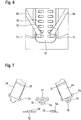
- Figures 5A and 5B show different configurations of the belt guides of the shoulder belts 23, 24 in the area of the cranial section 14 of the recliner rail.
- Figure 5A shows a variant where the belts are guided through recesses in the recliner rail and preferably run freely there.
- a plurality of bushings 17 spaced apart from one another can be provided on the recliner rail in order to adapt the position of the belt guide.
- An alternative and preferred embodiment shows Figure 5B where separate guide eyes 18 guide the straps. The guide eyes can be fixed in a variable position on the recliner rail 10.
- FIG 6 shows a detailed view of the anchoring of the straps 24 or 23 on the caudal section 12 of the recliner by means of anchor eyes 71, in which the straps 24 or 23 are guided and fixed there.
- the anchor eyelets 71 can be variably fixed in anchoring points 16 formed on the recliner rail.
- FIG 7 Detailed views of the anchor eyelets 71 in plan and sectional views.
- the anchor eyelets have a locking lug 72 with an undercut and shoulder 74, which are specifically designed to engage in appropriately designed anchoring points 16 of the recliner rail 10 and, after being rotated into the corresponding working angle, are protected there against falling out due to the shoulder 74, but to prevent them from falling out Latch 72 are pivotable.
- the belt ends there, after they have been passed through the anchor eyelets 71 are firmly sewn onto connecting surfaces 21 or are hooked or looped or hooked to themselves.
- FIG 8 an overall view of the reclination orthosis according to the above Figures 1 to 7 .
- the belt ends 25, 26 are preferably additionally provided with engagement pockets 22, with which the patient can better grip the belt ends 25, 26 for tensioning.
- the fleece zones 34 of the two bandage ends 31 and 32 are provided on the one hand for their mutual Velcro and on the other hand for receiving the belt ends 25, 26 provided with Velcro elements.
Landscapes
- Health & Medical Sciences (AREA)
- Nursing (AREA)
- Orthopedic Medicine & Surgery (AREA)
- Engineering & Computer Science (AREA)
- Biomedical Technology (AREA)
- Heart & Thoracic Surgery (AREA)
- Vascular Medicine (AREA)
- Life Sciences & Earth Sciences (AREA)
- Animal Behavior & Ethology (AREA)
- General Health & Medical Sciences (AREA)
- Public Health (AREA)
- Veterinary Medicine (AREA)
- Orthopedics, Nursing, And Contraception (AREA)
Claims (10)
- Orthèse de réclination pour application à un patient, incluant une ceinture de bassin (30), un rail réclinateur rigide (10) et deux sangles d'épaule (23, 24) individuelles pouvant être tendues, caractérisée en ce que, lorsque l'orthèse de réclination est appliquée au patient, les sangles d'épaule (23, 24) forment respectivement, en montant depuis une section caudale (12) du rail réclinateur (10), une section de bretelle ipsilatérale respective (20) et, de là, s'étendent en retour par le biais d'œillets de guidage (18) sur une section crânienne (14) du rail réclinateur (10), où elles se croisent en un point de croisement central dorsal (29) et de là s'étendent en descendant de manière contralatérale, où elles se croisent en des points de croisement latéraux thoraciques (27, 28) avec la sangle ipsilatérale respectivement montante, et se terminent ensuite en extrémités ventrales de sangles (25, 26), lesquelles peuvent être immobilisées sous tension au niveau d'une section ventrale (33) de la ceinture de bassin (30).
- Orthèse de réclination selon la revendication 1, dans laquelle les sangles ipsilatérale et contralatérale (23, 24) se croisent respectivement à angle approximativement droit aux deux points de croisement latéraux thoraciques (27, 28).
- Orthèse de réclination selon la revendication 1 ou 2, dans laquelle les deux sangles (23, 24) passent librement respectivement sur les trois points de croisement (27, 28, 29) et dans les œillets de guidage (18) et peuvent être fixées exclusivement à la section caudale (12) du rail réclinateur (10) et peuvent être immobilisées par leurs extrémités de sangles (25, 26) au niveau de la section ventrale de ceinture de bassin (33).
- Orthèse de réclination selon l'une des revendications 1 à 3, dans laquelle les sangles (23, 24) sont guidées en passage libre dans des guidages d'intersection (42) dans les deux points de croisement latéraux thoraciques (27, 28).
- Orthèse de réclination selon l'une des revendications 1 à 3, dans laquelle les sangles (23, 24) sont guidées dans des guidages d'intersection (42) dans les deux points de croisement latéraux thoraciques (27, 28) et peuvent y être immobilisées.
- Orthèse de réclination selon l'une des revendications précédentes, dans laquelle la section caudale (12) du rail réclinateur (10) est positionnable dans la hauteur de l'articulation sacro-iliaque et la section crânienne (14) du rail réclinateur (10) est positionnable sur les vertèbres thoraciques supérieures ou les vertèbres cervicales.
- Orthèse de réclination selon l'une des revendications précédentes, dans laquelle les sangles (23, 24) sont guidées respectivement par des œillets d'ancrage (71) à leur point de sortie sur la section caudale (12) du rail réclinateur (10) et y sont fixés, dans laquelle les œillets d'ancrage (71) sont immobilisés dans des points d'ancrage (16) réalisés au niveau du rail réclinateur (10).
- Orthèse de réclination selon la revendication 7, dans laquelle le rail réclinateur (10) comporte plusieurs points d'ancrage (16) au moins dans sa section caudale (12), dans lesquels les sangles pouvant être immobilisées de manière respectivement variable en position pour adapter l'effet d'réclinaison au moyen d'œillets d'ancrage (71).
- Orthèse de réclination selon l'une des revendications précédentes, dans laquelle la ceinture de bassin (30) peut être positionnée sur le pelvis et la crête iliaque, à savoir en-dessous du ventre, et peut être y être immobilisée sous tension.
- Orthèse de réclination selon l'une des revendications précédentes, dans laquelle la force de soutien permettant de soutenir la colonne vertébrale thoracique et lombaire peut être complètement obtenue, après application de la ceinture de bassin sur le pelvis et la crête iliaque, par traction des deux extrémités de sangles (25, 26) des deux sangles individuelles libres (23, 24) et immobilisation sous tension au niveau de la section ventrale de ceinture de bassin (33).
Applications Claiming Priority (2)
| Application Number | Priority Date | Filing Date | Title |
|---|---|---|---|
| DE102016201270.3A DE102016201270A1 (de) | 2016-01-28 | 2016-01-28 | Zuggurt-Reklinationsorthese |
| PCT/EP2017/051803 WO2017129762A1 (fr) | 2016-01-28 | 2017-01-27 | Orthèse de réclinaison à sangles de traction |
Publications (2)
| Publication Number | Publication Date |
|---|---|
| EP3407842A1 EP3407842A1 (fr) | 2018-12-05 |
| EP3407842B1 true EP3407842B1 (fr) | 2020-05-27 |
Family
ID=57960427
Family Applications (1)
| Application Number | Title | Priority Date | Filing Date |
|---|---|---|---|
| EP17702826.3A Active EP3407842B1 (fr) | 2016-01-28 | 2017-01-27 | Orthèse de réclinaison à sangles de traction |
Country Status (9)
| Country | Link |
|---|---|
| US (1) | US10426650B2 (fr) |
| EP (1) | EP3407842B1 (fr) |
| CN (1) | CN108601666B (fr) |
| CA (1) | CA3012897C (fr) |
| DE (1) | DE102016201270A1 (fr) |
| ES (1) | ES2801776T3 (fr) |
| MX (1) | MX367681B (fr) |
| RU (1) | RU2701579C1 (fr) |
| WO (1) | WO2017129762A1 (fr) |
Cited By (3)
| Publication number | Priority date | Publication date | Assignee | Title |
|---|---|---|---|---|
| DE202021106539U1 (de) | 2021-11-30 | 2021-12-14 | Spektramed Gmbh | Rückenorthesevorrichtung insbesondere zur Reklination sowie Verwendung |
| WO2022234046A1 (fr) * | 2021-05-07 | 2022-11-10 | Bauerfeind Ag | Ceinture de soutien dorsal |
| DE102021131494B3 (de) | 2021-11-30 | 2023-04-27 | Spektramed Gmbh | Rückenorthesevorrichtung insbesondere zur Reklination sowie modulares Orthesensystem und Verwendung |
Families Citing this family (22)
| Publication number | Priority date | Publication date | Assignee | Title |
|---|---|---|---|---|
| GB2552009B (en) * | 2016-07-06 | 2022-05-04 | The Spinecorporation Ltd | A brace and a method of fitting a brace |
| US20190298068A1 (en) * | 2018-03-28 | 2019-10-03 | Shirley Tan | Apparatus and system for improving sitting posture |
| CN108057817B (zh) * | 2017-12-11 | 2024-08-09 | 广东能洋电力建设有限公司 | 线缆机拉线器 |
| ES2878199T3 (es) * | 2018-03-08 | 2021-11-18 | Medi Gmbh & Co Kg | Ortesis modular, en particular para pacientes que sufren osteoporosis |
| DE102018211431A1 (de) | 2018-07-10 | 2020-01-16 | Bauerfeind Ag | Rückenstützgurt |
| JP6650973B2 (ja) * | 2018-07-31 | 2020-02-19 | ユーピーアール株式会社 | アシストスーツ |
| CN109288617B (zh) * | 2018-10-23 | 2024-12-06 | 河南逸兰假肢矫形器有限公司 | 一种脊柱侧弯矫正器 |
| CN109700585A (zh) * | 2018-11-26 | 2019-05-03 | 上海谐趣技术有限公司 | 一种三维脊椎姿态维持装置 |
| DE102018009316A1 (de) | 2018-11-27 | 2020-05-28 | Bort Gmbh | Rückenorthese zum Stabilisieren des Rückens eines Patienten und Verfahren zum Anlegen der Rückenorthese |
| EP4096594A1 (fr) * | 2020-01-29 | 2022-12-07 | Djo, Llc | Appareil orthopédique d'immobilisation de l'épaule |
| US11931282B2 (en) * | 2020-10-15 | 2024-03-19 | The Hong Kong Polytechnic University | Bracewear for spinal correction and system for posture training |
| CN116546898B (zh) * | 2020-10-29 | 2025-09-23 | 丝丽果集团 | 用于乳房矫形及胸椎矫正的女性上衣 |
| US11771580B2 (en) * | 2020-11-25 | 2023-10-03 | Deroyal Industries, Inc. | TLSO/LSO spine brace |
| DE102021117132B4 (de) * | 2021-07-02 | 2025-11-20 | ax-lightness composites GmbH | Thorax-Orthese |
| CN113303959B (zh) * | 2021-07-02 | 2022-06-21 | 国家康复辅具研究中心 | 一种脊柱免荷辅具 |
| JP7730143B2 (ja) * | 2021-10-13 | 2025-08-27 | 日本シグマックス株式会社 | 姿勢矯正装具 |
| US20230149199A1 (en) * | 2021-11-15 | 2023-05-18 | Aspen Medical Products, Llc | Orthopedic brace having an adjustable spinal support extension and support harness |
| US11896510B2 (en) * | 2021-12-18 | 2024-02-13 | Kenneth K. Hansraj | Spine force modulating assembly |
| US12447037B1 (en) * | 2021-12-18 | 2025-10-21 | Kenneth K. Hansraj | Spine force modulating assembly |
| US12144760B2 (en) * | 2022-01-03 | 2024-11-19 | Wear Etalon Corporation | Posture enhancing top |
| FR3159511B1 (fr) * | 2024-02-28 | 2026-02-27 | Thuasne | Dispositif correcteur de posture |
| USD1105441S1 (en) | 2025-01-13 | 2025-12-09 | Yinghuoshenghuo (Shenzhen) Technology Co., Ltd. | Corrective back brace |
Citations (1)
| Publication number | Priority date | Publication date | Assignee | Title |
|---|---|---|---|---|
| CN201631437U (zh) * | 2010-01-27 | 2010-11-17 | 橡果信息科技(上海)有限公司 | 束身矫姿带 |
Family Cites Families (28)
| Publication number | Priority date | Publication date | Assignee | Title |
|---|---|---|---|---|
| US690096A (en) * | 1901-05-18 | 1901-12-31 | Lucy Alida Bower | Shoulder-braces. |
| US996343A (en) * | 1908-08-01 | 1911-06-27 | Edward JOHNSON | Shoulder-brace. |
| US940775A (en) * | 1908-11-13 | 1909-11-23 | Joel U Adams | Shoulder-brace. |
| US945359A (en) * | 1909-05-20 | 1910-01-04 | Joel U Adams | Body-brace. |
| US1100499A (en) * | 1913-03-19 | 1914-06-16 | Edward Featherston | Shoulder-brace. |
| US1386067A (en) * | 1920-06-09 | 1921-08-02 | Mason Mayor | Shoulder and body brace |
| US1532304A (en) * | 1923-11-17 | 1925-04-07 | Donald V Cunning | Body brace |
| US3282264A (en) * | 1964-02-03 | 1966-11-01 | S H Camp & Company | Back brace |
| IE55507B1 (en) * | 1984-05-22 | 1990-10-10 | Daniel John Mcnamara | A spinal support |
| CN2119897U (zh) * | 1992-04-28 | 1992-10-28 | 焦世瑜 | 脊椎肩部畸形矫正器 |
| RU2161937C2 (ru) * | 1997-10-30 | 2001-01-20 | Никитин Валентин Викторович | Фиксирующе-реклинирующий корсет |
| CN2335587Y (zh) * | 1998-03-06 | 1999-09-01 | 刘兴志 | 驼背近视矫正带 |
| CN2335592Y (zh) * | 1998-05-28 | 1999-09-01 | 周利民 | 人体姿势矫形、防近视理疗带 |
| CN2376877Y (zh) * | 1998-11-12 | 2000-05-10 | 周利民 | 矫姿、防近视带 |
| DE10329454A1 (de) * | 2003-07-01 | 2005-01-27 | Dj Orthopedics Deutschland Gmbh | Orthopädische Stützeinrichtung für Rücken- und Lumbalbereich |
| ITVR20050125A1 (it) * | 2005-10-12 | 2007-04-13 | Fgp Srl | Supporto ortopedico od ortesi dorsale per colonna vertebrale |
| US7833182B2 (en) * | 2007-03-14 | 2010-11-16 | Hughes Phillip K | Back support apparatus and method |
| US20100318010A1 (en) | 2007-10-17 | 2010-12-16 | Sandifer Alan T | Adjustable posterior spinal orthosis |
| DE102007062274A1 (de) * | 2007-12-14 | 2009-06-18 | Bort Gmbh | Orthopädische Stützeinrichtung für einen menschlichen Rücken- und Lumbalbereich |
| US8657769B2 (en) * | 2009-11-04 | 2014-02-25 | Ossur Hf | Thoracic lumbar sacral orthosis |
| AU2010358710A1 (en) * | 2010-08-03 | 2013-03-21 | Von Zieglauer, Elizabeth | Orthopaedic device |
| ITMI20110461A1 (it) * | 2011-03-24 | 2012-09-25 | Orthoservice Ag | Corsetto ortopedico regolabile per il supporto della colonna vertebrale |
| US9572705B2 (en) * | 2012-01-13 | 2017-02-21 | Ossur Hf | Spinal orthosis |
| US9849021B2 (en) * | 2012-05-15 | 2017-12-26 | F.G.P. S.R.L. | Orthopedic back support or vertebral column brace |
| RU2498788C1 (ru) * | 2012-06-13 | 2013-11-20 | Государственное бюджетное образовательное учреждение высшего профессионального образования Дальневосточный государственный медицинский университет | Комплект ортопедический |
| BR112015018410A2 (pt) * | 2013-02-07 | 2017-07-18 | Deroyal Ind Inc | cinta de suporte de extensão lombar dorsal com sistema de tensionamento |
| CN202892156U (zh) * | 2013-02-27 | 2013-04-24 | 李本楠 | 一种日常用脊柱矫直器 |
| MX368226B (es) * | 2013-03-25 | 2019-09-25 | Chaleco de levantamiento de auto-activación con respuesta sensorial y métodos de uso del mismo. |
-
2016
- 2016-01-28 DE DE102016201270.3A patent/DE102016201270A1/de not_active Ceased
-
2017
- 2017-01-27 WO PCT/EP2017/051803 patent/WO2017129762A1/fr not_active Ceased
- 2017-01-27 ES ES17702826T patent/ES2801776T3/es active Active
- 2017-01-27 EP EP17702826.3A patent/EP3407842B1/fr active Active
- 2017-01-27 US US16/072,740 patent/US10426650B2/en active Active
- 2017-01-27 MX MX2018009162A patent/MX367681B/es active IP Right Grant
- 2017-01-27 CA CA3012897A patent/CA3012897C/fr active Active
- 2017-01-27 CN CN201780008731.2A patent/CN108601666B/zh active Active
- 2017-01-27 RU RU2018129323A patent/RU2701579C1/ru active
Patent Citations (1)
| Publication number | Priority date | Publication date | Assignee | Title |
|---|---|---|---|---|
| CN201631437U (zh) * | 2010-01-27 | 2010-11-17 | 橡果信息科技(上海)有限公司 | 束身矫姿带 |
Cited By (4)
| Publication number | Priority date | Publication date | Assignee | Title |
|---|---|---|---|---|
| WO2022234046A1 (fr) * | 2021-05-07 | 2022-11-10 | Bauerfeind Ag | Ceinture de soutien dorsal |
| US12521266B2 (en) | 2021-05-07 | 2026-01-13 | Bauerfeind Ag | Back support belt |
| DE202021106539U1 (de) | 2021-11-30 | 2021-12-14 | Spektramed Gmbh | Rückenorthesevorrichtung insbesondere zur Reklination sowie Verwendung |
| DE102021131494B3 (de) | 2021-11-30 | 2023-04-27 | Spektramed Gmbh | Rückenorthesevorrichtung insbesondere zur Reklination sowie modulares Orthesensystem und Verwendung |
Also Published As
| Publication number | Publication date |
|---|---|
| CA3012897C (fr) | 2019-09-24 |
| EP3407842A1 (fr) | 2018-12-05 |
| DE102016201270A1 (de) | 2017-08-03 |
| MX2018009162A (es) | 2018-11-19 |
| RU2701579C1 (ru) | 2019-09-30 |
| CN108601666A (zh) | 2018-09-28 |
| US20190029866A1 (en) | 2019-01-31 |
| ES2801776T3 (es) | 2021-01-13 |
| CA3012897A1 (fr) | 2017-08-03 |
| MX367681B (es) | 2019-09-02 |
| US10426650B2 (en) | 2019-10-01 |
| CN108601666B (zh) | 2020-11-13 |
| WO2017129762A1 (fr) | 2017-08-03 |
Similar Documents
| Publication | Publication Date | Title |
|---|---|---|
| EP3407842B1 (fr) | Orthèse de réclinaison à sangles de traction | |
| EP2844197B1 (fr) | Dispositif tendeur pour orthèses | |
| DE2837620A1 (de) | Rueckenstuetzbandage | |
| DE29720475U1 (de) | Minimalorthese zur Behandlung der Osteoporose | |
| DE20204747U1 (de) | Wirbelsäulenorthese | |
| EP3820414A1 (fr) | Ceinture de soutien dorsal | |
| DE2211015C3 (de) | Tragbahre zum Transport von Personen mit Wirbelsäulenverletzungen oder Brüchen des Oberschenkelhalsknochens | |
| EP2874579B1 (fr) | Orthèse d'abduction d'épaule | |
| WO2012022470A1 (fr) | Dispositif tendeur pour orthèses | |
| EP3107508B1 (fr) | Orthèse de tronc | |
| DE202013000914U1 (de) | Lumbalorthese | |
| EP1398010B1 (fr) | Bandage claviculaire | |
| DE202024102521U1 (de) | Hüftorthese zur Mobilisierung eines Hüftgelenks | |
| DE10359105A1 (de) | Reklinationskorsett | |
| EP3536285A1 (fr) | Orthèse modulaire, en particulier pour patients atteints d'ostéoporose | |
| WO2010139084A1 (fr) | Orthèse | |
| EP4368154B1 (fr) | Orthèse dorsale | |
| DE102022117881B4 (de) | Orthese oder bandage für den lumbalbereich | |
| EP4333779B1 (fr) | Ceinture de soutien dorsal | |
| DE20204936U1 (de) | Dynamisierte Reklinationsorthese mit Sternal- und Symphysenpelotte | |
| DE102007012557B3 (de) | Bauchspanngurt | |
| DE2000045A1 (de) | Geraet zur Streckung der Wirbelsaeule | |
| DE102021120725A1 (de) | Vorrichtung zur Behandlung der menschlichen Wirbelsäule | |
| DE947332C (de) | Streckguertel fuer die Behandlung von Rueckenverletzungen | |
| DE20308328U1 (de) | Clavicula-Bandage |
Legal Events
| Date | Code | Title | Description |
|---|---|---|---|
| STAA | Information on the status of an ep patent application or granted ep patent |
Free format text: STATUS: UNKNOWN |
|
| STAA | Information on the status of an ep patent application or granted ep patent |
Free format text: STATUS: THE INTERNATIONAL PUBLICATION HAS BEEN MADE |
|
| PUAI | Public reference made under article 153(3) epc to a published international application that has entered the european phase |
Free format text: ORIGINAL CODE: 0009012 |
|
| STAA | Information on the status of an ep patent application or granted ep patent |
Free format text: STATUS: REQUEST FOR EXAMINATION WAS MADE |
|
| 17P | Request for examination filed |
Effective date: 20180828 |
|
| AK | Designated contracting states |
Kind code of ref document: A1 Designated state(s): AL AT BE BG CH CY CZ DE DK EE ES FI FR GB GR HR HU IE IS IT LI LT LU LV MC MK MT NL NO PL PT RO RS SE SI SK SM TR |
|
| AX | Request for extension of the european patent |
Extension state: BA ME |
|
| DAV | Request for validation of the european patent (deleted) | ||
| DAX | Request for extension of the european patent (deleted) | ||
| GRAP | Despatch of communication of intention to grant a patent |
Free format text: ORIGINAL CODE: EPIDOSNIGR1 |
|
| STAA | Information on the status of an ep patent application or granted ep patent |
Free format text: STATUS: GRANT OF PATENT IS INTENDED |
|
| INTG | Intention to grant announced |
Effective date: 20191220 |
|
| GRAS | Grant fee paid |
Free format text: ORIGINAL CODE: EPIDOSNIGR3 |
|
| GRAA | (expected) grant |
Free format text: ORIGINAL CODE: 0009210 |
|
| STAA | Information on the status of an ep patent application or granted ep patent |
Free format text: STATUS: THE PATENT HAS BEEN GRANTED |
|
| AK | Designated contracting states |
Kind code of ref document: B1 Designated state(s): AL AT BE BG CH CY CZ DE DK EE ES FI FR GB GR HR HU IE IS IT LI LT LU LV MC MK MT NL NO PL PT RO RS SE SI SK SM TR |
|
| REG | Reference to a national code |
Ref country code: GB Ref legal event code: FG4D Free format text: NOT ENGLISH |
|
| REG | Reference to a national code |
Ref country code: CH Ref legal event code: EP |
|
| REG | Reference to a national code |
Ref country code: AT Ref legal event code: REF Ref document number: 1273756 Country of ref document: AT Kind code of ref document: T Effective date: 20200615 Ref country code: CH Ref legal event code: NV Representative=s name: OFFICE ERNEST T. FREYLINGER S.A., CH |
|
| REG | Reference to a national code |
Ref country code: DE Ref legal event code: R096 Ref document number: 502017005441 Country of ref document: DE |
|
| REG | Reference to a national code |
Ref country code: NL Ref legal event code: FP |
|
| REG | Reference to a national code |
Ref country code: LT Ref legal event code: MG4D |
|
| PG25 | Lapsed in a contracting state [announced via postgrant information from national office to epo] |
Ref country code: FI Free format text: LAPSE BECAUSE OF FAILURE TO SUBMIT A TRANSLATION OF THE DESCRIPTION OR TO PAY THE FEE WITHIN THE PRESCRIBED TIME-LIMIT Effective date: 20200527 Ref country code: NO Free format text: LAPSE BECAUSE OF FAILURE TO SUBMIT A TRANSLATION OF THE DESCRIPTION OR TO PAY THE FEE WITHIN THE PRESCRIBED TIME-LIMIT Effective date: 20200827 Ref country code: PT Free format text: LAPSE BECAUSE OF FAILURE TO SUBMIT A TRANSLATION OF THE DESCRIPTION OR TO PAY THE FEE WITHIN THE PRESCRIBED TIME-LIMIT Effective date: 20200928 Ref country code: IS Free format text: LAPSE BECAUSE OF FAILURE TO SUBMIT A TRANSLATION OF THE DESCRIPTION OR TO PAY THE FEE WITHIN THE PRESCRIBED TIME-LIMIT Effective date: 20200927 Ref country code: SE Free format text: LAPSE BECAUSE OF FAILURE TO SUBMIT A TRANSLATION OF THE DESCRIPTION OR TO PAY THE FEE WITHIN THE PRESCRIBED TIME-LIMIT Effective date: 20200527 Ref country code: GR Free format text: LAPSE BECAUSE OF FAILURE TO SUBMIT A TRANSLATION OF THE DESCRIPTION OR TO PAY THE FEE WITHIN THE PRESCRIBED TIME-LIMIT Effective date: 20200828 Ref country code: LT Free format text: LAPSE BECAUSE OF FAILURE TO SUBMIT A TRANSLATION OF THE DESCRIPTION OR TO PAY THE FEE WITHIN THE PRESCRIBED TIME-LIMIT Effective date: 20200527 |
|
| PG25 | Lapsed in a contracting state [announced via postgrant information from national office to epo] |
Ref country code: BG Free format text: LAPSE BECAUSE OF FAILURE TO SUBMIT A TRANSLATION OF THE DESCRIPTION OR TO PAY THE FEE WITHIN THE PRESCRIBED TIME-LIMIT Effective date: 20200827 Ref country code: LV Free format text: LAPSE BECAUSE OF FAILURE TO SUBMIT A TRANSLATION OF THE DESCRIPTION OR TO PAY THE FEE WITHIN THE PRESCRIBED TIME-LIMIT Effective date: 20200527 Ref country code: RS Free format text: LAPSE BECAUSE OF FAILURE TO SUBMIT A TRANSLATION OF THE DESCRIPTION OR TO PAY THE FEE WITHIN THE PRESCRIBED TIME-LIMIT Effective date: 20200527 Ref country code: HR Free format text: LAPSE BECAUSE OF FAILURE TO SUBMIT A TRANSLATION OF THE DESCRIPTION OR TO PAY THE FEE WITHIN THE PRESCRIBED TIME-LIMIT Effective date: 20200527 |
|
| PG25 | Lapsed in a contracting state [announced via postgrant information from national office to epo] |
Ref country code: AL Free format text: LAPSE BECAUSE OF FAILURE TO SUBMIT A TRANSLATION OF THE DESCRIPTION OR TO PAY THE FEE WITHIN THE PRESCRIBED TIME-LIMIT Effective date: 20200527 |
|
| REG | Reference to a national code |
Ref country code: ES Ref legal event code: FG2A Ref document number: 2801776 Country of ref document: ES Kind code of ref document: T3 Effective date: 20210113 |
|
| PG25 | Lapsed in a contracting state [announced via postgrant information from national office to epo] |
Ref country code: DK Free format text: LAPSE BECAUSE OF FAILURE TO SUBMIT A TRANSLATION OF THE DESCRIPTION OR TO PAY THE FEE WITHIN THE PRESCRIBED TIME-LIMIT Effective date: 20200527 Ref country code: SM Free format text: LAPSE BECAUSE OF FAILURE TO SUBMIT A TRANSLATION OF THE DESCRIPTION OR TO PAY THE FEE WITHIN THE PRESCRIBED TIME-LIMIT Effective date: 20200527 Ref country code: EE Free format text: LAPSE BECAUSE OF FAILURE TO SUBMIT A TRANSLATION OF THE DESCRIPTION OR TO PAY THE FEE WITHIN THE PRESCRIBED TIME-LIMIT Effective date: 20200527 Ref country code: CZ Free format text: LAPSE BECAUSE OF FAILURE TO SUBMIT A TRANSLATION OF THE DESCRIPTION OR TO PAY THE FEE WITHIN THE PRESCRIBED TIME-LIMIT Effective date: 20200527 Ref country code: RO Free format text: LAPSE BECAUSE OF FAILURE TO SUBMIT A TRANSLATION OF THE DESCRIPTION OR TO PAY THE FEE WITHIN THE PRESCRIBED TIME-LIMIT Effective date: 20200527 |
|
| PG25 | Lapsed in a contracting state [announced via postgrant information from national office to epo] |
Ref country code: PL Free format text: LAPSE BECAUSE OF FAILURE TO SUBMIT A TRANSLATION OF THE DESCRIPTION OR TO PAY THE FEE WITHIN THE PRESCRIBED TIME-LIMIT Effective date: 20200527 Ref country code: SK Free format text: LAPSE BECAUSE OF FAILURE TO SUBMIT A TRANSLATION OF THE DESCRIPTION OR TO PAY THE FEE WITHIN THE PRESCRIBED TIME-LIMIT Effective date: 20200527 |
|
| REG | Reference to a national code |
Ref country code: DE Ref legal event code: R097 Ref document number: 502017005441 Country of ref document: DE |
|
| PLBE | No opposition filed within time limit |
Free format text: ORIGINAL CODE: 0009261 |
|
| STAA | Information on the status of an ep patent application or granted ep patent |
Free format text: STATUS: NO OPPOSITION FILED WITHIN TIME LIMIT |
|
| 26N | No opposition filed |
Effective date: 20210302 |
|
| PG25 | Lapsed in a contracting state [announced via postgrant information from national office to epo] |
Ref country code: SI Free format text: LAPSE BECAUSE OF FAILURE TO SUBMIT A TRANSLATION OF THE DESCRIPTION OR TO PAY THE FEE WITHIN THE PRESCRIBED TIME-LIMIT Effective date: 20200527 |
|
| PG25 | Lapsed in a contracting state [announced via postgrant information from national office to epo] |
Ref country code: MC Free format text: LAPSE BECAUSE OF FAILURE TO SUBMIT A TRANSLATION OF THE DESCRIPTION OR TO PAY THE FEE WITHIN THE PRESCRIBED TIME-LIMIT Effective date: 20200527 |
|
| PG25 | Lapsed in a contracting state [announced via postgrant information from national office to epo] |
Ref country code: LU Free format text: LAPSE BECAUSE OF NON-PAYMENT OF DUE FEES Effective date: 20210127 |
|
| REG | Reference to a national code |
Ref country code: BE Ref legal event code: MM Effective date: 20210131 |
|
| PG25 | Lapsed in a contracting state [announced via postgrant information from national office to epo] |
Ref country code: IE Free format text: LAPSE BECAUSE OF NON-PAYMENT OF DUE FEES Effective date: 20210127 |
|
| PG25 | Lapsed in a contracting state [announced via postgrant information from national office to epo] |
Ref country code: BE Free format text: LAPSE BECAUSE OF NON-PAYMENT OF DUE FEES Effective date: 20210131 |
|
| PG25 | Lapsed in a contracting state [announced via postgrant information from national office to epo] |
Ref country code: CY Free format text: LAPSE BECAUSE OF FAILURE TO SUBMIT A TRANSLATION OF THE DESCRIPTION OR TO PAY THE FEE WITHIN THE PRESCRIBED TIME-LIMIT Effective date: 20200527 |
|
| PG25 | Lapsed in a contracting state [announced via postgrant information from national office to epo] |
Ref country code: HU Free format text: LAPSE BECAUSE OF FAILURE TO SUBMIT A TRANSLATION OF THE DESCRIPTION OR TO PAY THE FEE WITHIN THE PRESCRIBED TIME-LIMIT; INVALID AB INITIO Effective date: 20170127 |
|
| P01 | Opt-out of the competence of the unified patent court (upc) registered |
Effective date: 20230628 |
|
| PG25 | Lapsed in a contracting state [announced via postgrant information from national office to epo] |
Ref country code: MK Free format text: LAPSE BECAUSE OF FAILURE TO SUBMIT A TRANSLATION OF THE DESCRIPTION OR TO PAY THE FEE WITHIN THE PRESCRIBED TIME-LIMIT Effective date: 20200527 |
|
| PG25 | Lapsed in a contracting state [announced via postgrant information from national office to epo] |
Ref country code: MT Free format text: LAPSE BECAUSE OF FAILURE TO SUBMIT A TRANSLATION OF THE DESCRIPTION OR TO PAY THE FEE WITHIN THE PRESCRIBED TIME-LIMIT Effective date: 20200527 |
|
| PGFP | Annual fee paid to national office [announced via postgrant information from national office to epo] |
Ref country code: CH Payment date: 20250201 Year of fee payment: 9 |
|
| PG25 | Lapsed in a contracting state [announced via postgrant information from national office to epo] |
Ref country code: TR Free format text: LAPSE BECAUSE OF FAILURE TO SUBMIT A TRANSLATION OF THE DESCRIPTION OR TO PAY THE FEE WITHIN THE PRESCRIBED TIME-LIMIT Effective date: 20200527 |
|
| REG | Reference to a national code |
Ref country code: CH Ref legal event code: U11 Free format text: ST27 STATUS EVENT CODE: U-0-0-U10-U11 (AS PROVIDED BY THE NATIONAL OFFICE) Effective date: 20260201 |
|
| PGFP | Annual fee paid to national office [announced via postgrant information from national office to epo] |
Ref country code: NL Payment date: 20260121 Year of fee payment: 10 |
|
| PGFP | Annual fee paid to national office [announced via postgrant information from national office to epo] |
Ref country code: GB Payment date: 20260123 Year of fee payment: 10 |
|
| PGFP | Annual fee paid to national office [announced via postgrant information from national office to epo] |
Ref country code: ES Payment date: 20260227 Year of fee payment: 10 |
|
| PGFP | Annual fee paid to national office [announced via postgrant information from national office to epo] |
Ref country code: DE Payment date: 20260129 Year of fee payment: 10 |
|
| PGFP | Annual fee paid to national office [announced via postgrant information from national office to epo] |
Ref country code: AT Payment date: 20260122 Year of fee payment: 10 |
|
| PGFP | Annual fee paid to national office [announced via postgrant information from national office to epo] |
Ref country code: IT Payment date: 20260123 Year of fee payment: 10 |
|
| PGFP | Annual fee paid to national office [announced via postgrant information from national office to epo] |
Ref country code: FR Payment date: 20260123 Year of fee payment: 10 |