EP3408128B1 - Dispositif de commande et procédé de charge d'une batterie rechargeable - Google Patents
Dispositif de commande et procédé de charge d'une batterie rechargeable Download PDFInfo
- Publication number
- EP3408128B1 EP3408128B1 EP16702404.1A EP16702404A EP3408128B1 EP 3408128 B1 EP3408128 B1 EP 3408128B1 EP 16702404 A EP16702404 A EP 16702404A EP 3408128 B1 EP3408128 B1 EP 3408128B1
- Authority
- EP
- European Patent Office
- Prior art keywords
- battery
- charging
- voltage
- determined
- control device
- Prior art date
- Legal status (The legal status is an assumption and is not a legal conclusion. Google has not performed a legal analysis and makes no representation as to the accuracy of the status listed.)
- Not-in-force
Links
Images

Classifications
-
- H—ELECTRICITY
- H02—GENERATION; CONVERSION OR DISTRIBUTION OF ELECTRIC POWER
- H02J—ELECTRIC POWER NETWORKS; CIRCUIT ARRANGEMENTS OR SYSTEMS FOR SUPPLYING OR DISTRIBUTING ELECTRIC POWER; SYSTEMS FOR STORING ELECTRIC ENERGY
- H02J7/00—Circuit arrangements for charging or discharging batteries or for supplying loads from batteries
- H02J7/60—Circuit arrangements for charging or discharging batteries or for supplying loads from batteries including safety or protection arrangements
- H02J7/663—Circuit arrangements for charging or discharging batteries or for supplying loads from batteries including safety or protection arrangements using battery or load disconnect circuits
-
- B—PERFORMING OPERATIONS; TRANSPORTING
- B60—VEHICLES IN GENERAL
- B60L—PROPULSION OF ELECTRICALLY-PROPELLED VEHICLES; SUPPLYING ELECTRIC POWER FOR AUXILIARY EQUIPMENT OF ELECTRICALLY-PROPELLED VEHICLES; ELECTRODYNAMIC BRAKE SYSTEMS FOR VEHICLES IN GENERAL; MAGNETIC SUSPENSION OR LEVITATION FOR VEHICLES; MONITORING OPERATING VARIABLES OF ELECTRICALLY-PROPELLED VEHICLES; ELECTRIC SAFETY DEVICES FOR ELECTRICALLY-PROPELLED VEHICLES
- B60L58/00—Methods or circuit arrangements for monitoring or controlling batteries or fuel cells, specially adapted for electric vehicles
- B60L58/10—Methods or circuit arrangements for monitoring or controlling batteries or fuel cells, specially adapted for electric vehicles for monitoring or controlling batteries
- B60L58/12—Methods or circuit arrangements for monitoring or controlling batteries or fuel cells, specially adapted for electric vehicles for monitoring or controlling batteries responding to state of charge [SoC]
- B60L58/15—Preventing overcharging
-
- G—PHYSICS
- G01—MEASURING; TESTING
- G01R—MEASURING ELECTRIC VARIABLES; MEASURING MAGNETIC VARIABLES
- G01R19/00—Arrangements for measuring currents or voltages or for indicating presence or sign thereof
- G01R19/165—Indicating that current or voltage is either above or below a predetermined value or within or outside a predetermined range of values
- G01R19/16533—Indicating that current or voltage is either above or below a predetermined value or within or outside a predetermined range of values characterised by the application
- G01R19/16538—Indicating that current or voltage is either above or below a predetermined value or within or outside a predetermined range of values characterised by the application in AC or DC supplies
- G01R19/16542—Indicating that current or voltage is either above or below a predetermined value or within or outside a predetermined range of values characterised by the application in AC or DC supplies for batteries
-
- G—PHYSICS
- G01—MEASURING; TESTING
- G01R—MEASURING ELECTRIC VARIABLES; MEASURING MAGNETIC VARIABLES
- G01R31/00—Arrangements for testing electric properties; Arrangements for locating electric faults; Arrangements for electrical testing characterised by what is being tested not provided for elsewhere
- G01R31/36—Arrangements for testing, measuring or monitoring the electrical condition of accumulators or electric batteries, e.g. capacity or state of charge [SoC]
- G01R31/382—Arrangements for monitoring battery or accumulator variables, e.g. SoC
- G01R31/3835—Arrangements for monitoring battery or accumulator variables, e.g. SoC involving only voltage measurements
-
- G—PHYSICS
- G01—MEASURING; TESTING
- G01R—MEASURING ELECTRIC VARIABLES; MEASURING MAGNETIC VARIABLES
- G01R31/00—Arrangements for testing electric properties; Arrangements for locating electric faults; Arrangements for electrical testing characterised by what is being tested not provided for elsewhere
- G01R31/36—Arrangements for testing, measuring or monitoring the electrical condition of accumulators or electric batteries, e.g. capacity or state of charge [SoC]
- G01R31/392—Determining battery ageing or deterioration, e.g. state of health
-
- H—ELECTRICITY
- H01—ELECTRIC ELEMENTS
- H01M—PROCESSES OR MEANS, e.g. BATTERIES, FOR THE DIRECT CONVERSION OF CHEMICAL ENERGY INTO ELECTRICAL ENERGY
- H01M10/00—Secondary cells; Manufacture thereof
- H01M10/42—Methods or arrangements for servicing or maintenance of secondary cells or secondary half-cells
- H01M10/48—Accumulators combined with arrangements for measuring, testing or indicating the condition of cells, e.g. the level or density of the electrolyte
- H01M10/486—Accumulators combined with arrangements for measuring, testing or indicating the condition of cells, e.g. the level or density of the electrolyte for measuring temperature
-
- H—ELECTRICITY
- H02—GENERATION; CONVERSION OR DISTRIBUTION OF ELECTRIC POWER
- H02J—ELECTRIC POWER NETWORKS; CIRCUIT ARRANGEMENTS OR SYSTEMS FOR SUPPLYING OR DISTRIBUTING ELECTRIC POWER; SYSTEMS FOR STORING ELECTRIC ENERGY
- H02J7/00—Circuit arrangements for charging or discharging batteries or for supplying loads from batteries
- H02J7/02—Circuit arrangements for charging or discharging batteries or for supplying loads from batteries for charging batteries from AC mains by converters
- H02J7/04—Regulation of charging current or voltage
-
- H—ELECTRICITY
- H02—GENERATION; CONVERSION OR DISTRIBUTION OF ELECTRIC POWER
- H02J—ELECTRIC POWER NETWORKS; CIRCUIT ARRANGEMENTS OR SYSTEMS FOR SUPPLYING OR DISTRIBUTING ELECTRIC POWER; SYSTEMS FOR STORING ELECTRIC ENERGY
- H02J7/00—Circuit arrangements for charging or discharging batteries or for supplying loads from batteries
- H02J7/60—Circuit arrangements for charging or discharging batteries or for supplying loads from batteries including safety or protection arrangements
- H02J7/64—Circuit arrangements for charging or discharging batteries or for supplying loads from batteries including safety or protection arrangements against overvoltage
-
- H—ELECTRICITY
- H02—GENERATION; CONVERSION OR DISTRIBUTION OF ELECTRIC POWER
- H02J—ELECTRIC POWER NETWORKS; CIRCUIT ARRANGEMENTS OR SYSTEMS FOR SUPPLYING OR DISTRIBUTING ELECTRIC POWER; SYSTEMS FOR STORING ELECTRIC ENERGY
- H02J7/00—Circuit arrangements for charging or discharging batteries or for supplying loads from batteries
- H02J7/90—Regulation of charging or discharging current or voltage
- H02J7/933—Regulation of charging or discharging current or voltage the cycle being controlled or terminated in response to electric parameters
-
- H—ELECTRICITY
- H02—GENERATION; CONVERSION OR DISTRIBUTION OF ELECTRIC POWER
- H02J—ELECTRIC POWER NETWORKS; CIRCUIT ARRANGEMENTS OR SYSTEMS FOR SUPPLYING OR DISTRIBUTING ELECTRIC POWER; SYSTEMS FOR STORING ELECTRIC ENERGY
- H02J7/00—Circuit arrangements for charging or discharging batteries or for supplying loads from batteries
- H02J7/90—Regulation of charging or discharging current or voltage
- H02J7/94—Regulation of charging or discharging current or voltage in response to battery current
-
- H—ELECTRICITY
- H02—GENERATION; CONVERSION OR DISTRIBUTION OF ELECTRIC POWER
- H02J—ELECTRIC POWER NETWORKS; CIRCUIT ARRANGEMENTS OR SYSTEMS FOR SUPPLYING OR DISTRIBUTING ELECTRIC POWER; SYSTEMS FOR STORING ELECTRIC ENERGY
- H02J7/00—Circuit arrangements for charging or discharging batteries or for supplying loads from batteries
- H02J7/90—Regulation of charging or discharging current or voltage
- H02J7/96—Regulation of charging or discharging current or voltage in response to battery voltage
-
- G—PHYSICS
- G01—MEASURING; TESTING
- G01R—MEASURING ELECTRIC VARIABLES; MEASURING MAGNETIC VARIABLES
- G01R31/00—Arrangements for testing electric properties; Arrangements for locating electric faults; Arrangements for electrical testing characterised by what is being tested not provided for elsewhere
- G01R31/36—Arrangements for testing, measuring or monitoring the electrical condition of accumulators or electric batteries, e.g. capacity or state of charge [SoC]
- G01R31/374—Arrangements for testing, measuring or monitoring the electrical condition of accumulators or electric batteries, e.g. capacity or state of charge [SoC] with means for correcting the measurement for temperature or ageing
-
- H—ELECTRICITY
- H01—ELECTRIC ELEMENTS
- H01M—PROCESSES OR MEANS, e.g. BATTERIES, FOR THE DIRECT CONVERSION OF CHEMICAL ENERGY INTO ELECTRICAL ENERGY
- H01M2220/00—Batteries for particular applications
- H01M2220/20—Batteries in motive systems, e.g. vehicle, ship, plane
-
- H—ELECTRICITY
- H02—GENERATION; CONVERSION OR DISTRIBUTION OF ELECTRIC POWER
- H02J—ELECTRIC POWER NETWORKS; CIRCUIT ARRANGEMENTS OR SYSTEMS FOR SUPPLYING OR DISTRIBUTING ELECTRIC POWER; SYSTEMS FOR STORING ELECTRIC ENERGY
- H02J7/00—Circuit arrangements for charging or discharging batteries or for supplying loads from batteries
- H02J7/60—Circuit arrangements for charging or discharging batteries or for supplying loads from batteries including safety or protection arrangements
- H02J7/61—Circuit arrangements for charging or discharging batteries or for supplying loads from batteries including safety or protection arrangements against overcharge
-
- H—ELECTRICITY
- H02—GENERATION; CONVERSION OR DISTRIBUTION OF ELECTRIC POWER
- H02J—ELECTRIC POWER NETWORKS; CIRCUIT ARRANGEMENTS OR SYSTEMS FOR SUPPLYING OR DISTRIBUTING ELECTRIC POWER; SYSTEMS FOR STORING ELECTRIC ENERGY
- H02J7/00—Circuit arrangements for charging or discharging batteries or for supplying loads from batteries
- H02J7/80—Circuit arrangements for charging or discharging batteries or for supplying loads from batteries including monitoring or indicating arrangements
- H02J7/82—Control of state of charge [SOC]
- H02J7/825—Detection of fully charged condition
-
- Y—GENERAL TAGGING OF NEW TECHNOLOGICAL DEVELOPMENTS; GENERAL TAGGING OF CROSS-SECTIONAL TECHNOLOGIES SPANNING OVER SEVERAL SECTIONS OF THE IPC; TECHNICAL SUBJECTS COVERED BY FORMER USPC CROSS-REFERENCE ART COLLECTIONS [XRACs] AND DIGESTS
- Y02—TECHNOLOGIES OR APPLICATIONS FOR MITIGATION OR ADAPTATION AGAINST CLIMATE CHANGE
- Y02E—REDUCTION OF GREENHOUSE GAS [GHG] EMISSIONS, RELATED TO ENERGY GENERATION, TRANSMISSION OR DISTRIBUTION
- Y02E60/00—Enabling technologies; Technologies with a potential or indirect contribution to GHG emissions mitigation
- Y02E60/10—Energy storage using batteries
-
- Y—GENERAL TAGGING OF NEW TECHNOLOGICAL DEVELOPMENTS; GENERAL TAGGING OF CROSS-SECTIONAL TECHNOLOGIES SPANNING OVER SEVERAL SECTIONS OF THE IPC; TECHNICAL SUBJECTS COVERED BY FORMER USPC CROSS-REFERENCE ART COLLECTIONS [XRACs] AND DIGESTS
- Y02—TECHNOLOGIES OR APPLICATIONS FOR MITIGATION OR ADAPTATION AGAINST CLIMATE CHANGE
- Y02T—CLIMATE CHANGE MITIGATION TECHNOLOGIES RELATED TO TRANSPORTATION
- Y02T10/00—Road transport of goods or passengers
- Y02T10/60—Other road transportation technologies with climate change mitigation effect
- Y02T10/70—Energy storage systems for electromobility, e.g. batteries
Definitions
- the present disclosure is related to a control device for controlling charging of a rechargeable battery and also to a method of charging of a rechargeable battery.
- Rechargeable batteries also called secondary cells
- Such vehicles may be hybrid vehicles comprising an internal combustion engine and one or more electric motors or purely electrically driven vehicles.
- a suitable rechargeable battery for such a vehicle may be a solid-state bipolar battery or other, e.g. liquid type batteries, in particular a laminated Li-ion battery.
- the rechargeable battery may be realized by a single cell or it may include a set of preferably identical cells. In the latter case the battery is also called a battery pack.
- the battery or the battery pack may further include a control device for controlling charging and/or discharging.
- the control device monitors state of charge (SOC) of the battery and it shall avoid the battery from operating outside its safe operating area.
- SOC state of charge
- Such a battery or battery pack is also called smart battery / smart battery pack. It is also possible that the control device is provided by the vehicle.
- One important aspect of charge control is to assure that any overcharging and/or over-discharging of the battery is avoided.
- the battery voltage may be monitored, which is increasing during charging. In case the determined battery voltage exceeds a predetermined upper voltage limit, it is recognized by the control device that the battery is fully charged and charging is stopped.
- the charging and discharging procedures may lead to a degradation of the laminated layers of the battery.
- the laminated electrodes may be affected by the degradation.
- the degradation leads to increased resistance which in turn increases the measured voltage of the battery during charging.
- the control device erroneously recognizes that the battery is fully charged. Although the battery is actually not yet fully charged (not SOC100%), charging is finished. This means that the available amount of energy decreases due to the degradation dispersion.
- EP 1 458 047 A2 discloses a charge control system for preventing overcharge of single cell layers.
- one of the positive and the negative electrode active material layer of the battery is made of a changeable electrode active material, and the other is made of an unchangeable electrode active material.
- the changeable electrode active material is an active material having a specific characteristic based on which the charging is controlled.
- WO2011001266 (A2 ) relates to a charge/discharge control of a vehicle having a battery, and an electric motor that receives electric power from the battery and produces driving force.
- a control device for controlling charging of a rechargeable battery.
- the control device is configured to:
- control device and the procedure performed by the control device are suitable for all types of solid-state bipolar batteries.
- control device may also be applied to other battery types, like liquid type batteries, as e.g. Li-ion batteries.
- the control device may further be configured to, when the determined voltage difference exceeds the predetermined threshold, increase the predetermined upper voltage limit by a predetermined voltage increment and restart charging of the battery, or restart charging of the battery for a limited time interval and re-determine the voltage difference after stopping charging.
- charging can be continued in a suitable extent by continually increasing the predetermined upper voltage limit or by continuing charging for one or more limited time periods.
- a further charging cycle can be performed by restarting charging and stopping charging, when the determined voltage exceeds the incremented predetermined upper voltage limit.
- charging is stopped after that time period automatically and the voltage difference is again compared with the predetermined threshold. Accordingly, said charging for a limited time period also defines a charging cycle. In other words the procedure of the invention can be performed repeatedly in several cycles, until the battery is actually fully charged.
- control device may be configured to set the upper voltage limit such that an overvoltage of the battery is avoided.
- the predetermined upper voltage limit does normally not constitute the actually critical upper limit but is rather chosen such that a new battery without degradation is charged until the desired full charge state is reached. Therefore this predetermined upper voltage limit may be increased, e.g. by 10%, 30%, 50% or 100%, without causing any actually dangerous overvoltage.
- the control device may further be configured to, when the determined voltage difference does not exceed the predetermined threshold, determine that the battery is fully charged and reset the predetermined threshold.
- control device may recognize based on the determined voltage difference, whether the battery is fully charged or charging has to be continued.
- the predetermined threshold may be determined each time the battery is charged. Therefore the predetermined threshold may also be reset, when charging has been completed.
- control device is configured to determine the threshold based on the state of charge of the battery before starting charging.
- the threshold may be determined before starting charging or when charging is started.
- the state of charge of the battery before charging is started may be more the lower limit of a predetermined allowed SOC range, e.g. 60%.
- the determined state of the charge (SOC) before starting charging may be considered when determining the threshold, as the SOC may have an influence on the determined voltage difference.
- the threshold namely depends on internal resistance of the battery. Also internal resistance depends on SOC of the battery. Therefore, when the SOC is low, it is preferable to increase the threshold. In other words, the lower the SOC is before starting charging, the more the threshold may be increased.
- the threshold is determined additionally or alternatively based on a determined degradation of the battery.
- the degradation of the battery may be determined based on a temperature / frequency distribution of the battery and a predetermined degradation rate of the battery.
- the determination of the degradation of the battery may be based on the Arrhenius equation.
- the temperature / frequency distribution of the battery may be determined by recording for each temperature of the battery how much time the battery had this temperature during its lifetime.
- the temperature data of the battery may be collected during the life time of the battery, i.e. during its usage and the rests between usages.
- the temperature / frequency distribution may be established by accumulating for each temperature the battery had during its past life time, how long the battery had this temperature.
- control device may comprise a voltage sensor for determining the voltage of the battery.
- This voltage sensor may also be used for determining the state of charge of the battery.
- control device may comprise a further voltage sensor for determining the state of charge of the battery.
- the control device may comprise a temperature sensor for determining the temperature of the battery.
- the disclosure further relates to a battery pack.
- the battery pack may comprise at least one battery, in particular a solid state bipolar battery, and a control device as described above.
- the disclosure further relates to a battery charging system.
- Said battery charging system may comprise at least one battery, in particular a solid state bipolar battery, a charging device for the battery, and a control device as described above.
- the disclosure relates to a vehicle comprising an electric motor and a battery pack, as described above.
- the vehicle may comprise an electric motor, at least one battery, in particular a solid state bipolar battery, and in addition a control device, as described above.
- the disclosure relates to a method of controlling charging of a rechargeable battery.
- the method comprises the steps of:
- the predetermined upper voltage limit is increased by a predetermined voltage increment and charging of the battery restarted, or charging of the battery is restarted for a limited time interval and after stopping charging the voltage difference is re-determined.
- the upper voltage limit may be set such that an overvoltage of the battery is avoided.
- the predetermined threshold When the determined voltage difference does not exceed the predetermined threshold, it is preferably determined that the battery is fully charged and the predetermined threshold may be reset.
- the degradation of the battery may be determined based on a temperature / frequency distribution of the battery and a predetermined degradation rate of the battery.
- the degradation of the battery may be determined based on the determined voltage difference.
- the determination of the degradation of the battery may be based on the Arrhenius equation.
- the temperature / frequency distribution of the battery may be determined by recording for each temperature of the battery how much time the battery had this temperature during its lifetime.
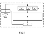
- Fig. 1 shows a schematic representation of a vehicle 1 comprising a control device 6 according to an embodiment of the present disclosure.
- the vehicle 1 may be a hybrid vehicle or an electric vehicle (i.e. a purely electrically driven vehicle).
- the vehicle 1 comprises at least one electric motor 4, which is powered by a battery or battery pack 2, preferably via an inverter 3.
- the vehicle is a hybrid vehicle, it further includes an internal combustion engine.
- the battery 2 may be a solid-state bipolar battery. However, it may also be another battery type, like a liquid type battery, as e.g. a Li-ion battery.
- the battery 2 is connected to a charging device 5 which is configured to charge the battery 2.
- the charging device 5 may comprise an electric control circuit, as e.g. a power electronics circuit.
- the charging device may further comprise or be connected to a connector for external charging by an external power source.
- the connector may be e.g. a plug or a wireless connector system.
- the charging device may further be connected to the electrical generator of the internal combustion engine of the vehicle. Consequently, the battery 2 may be charged, when the internal combustion engine is operating and/or when the vehicle is connected to an external power source.
- the battery 2 may be discharged, in order to operate the vehicle 1, in particular the electric motor 4.
- the battery 2 may further be discharged in a battery treatment and/or recovery procedure.
- control device 6 In order to control charging and discharging the vehicle 2 is provided with the control device 6 and sensors 7.
- the control device 6 monitors the battery 2 via the sensors 7 and controls the charging device 5.
- the control device 6 and/or the sensors 7 may also be comprised by the battery 2.
- the control device may be an electronic control circuit (ECU). It may also comprise a data storage.
- the vehicle comprises a smart battery charging system with a smart battery and a smart charging device. In other words, both the battery and the vehicle may comprise each an ECU which operate together and form together the control device according to the invention.
- the control device 6 may comprise or may be part of a battery management system.
- the control device 6 may comprise an application specific integrated circuit (ASIC), an electronic circuit, a processor (shared, dedicated, or group), a combinational logic circuit, a memory that executes one or more software programs, and/or other suitable components that provide the described functionality of the control device 6.
- ASIC application specific integrated circuit
- processor shared, dedicated, or group
- combinational logic circuit a memory that executes one or more software programs, and/or other suitable components that provide the described functionality of the control device 6.
- the sensors 7 may comprise one or more temperature sensors 8 for measuring the temperature of the battery 2, an SOC (state of charge) sensor 9 for measuring the state of charge of the battery 2 and a voltage sensor 10 for measuring the voltage of the battery.
- the SOC sensor 9 may also be a voltage sensor, wherein the measured voltage is used to determine the SOC of the battery. In this case the SOC sensor may be the same sensor as the voltage sensor 10 or it may be an additional sensor. Of course, the SOC sensor 9 may also comprise other sensor types to determine the SOC of the battery, as it is well known in the art.
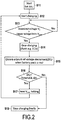
- Fig. 2 shows a flow chart of the general charging control procedure according to an embodiment of the present disclosure.
- the control device 6 is configured to carry out this procedure of fig. 2 .
- step S11 the procedure is started.
- the start may be triggered by a determination of the control device that charging of the battery is necessary (e.g. due to a low SOC) and/or by the fact that charging becomes possible (e.g. due to operation of the internal combustion engine or due to a connection to an external electrical power source).
- the threshold ⁇ V T may be determined. This determination procedure is described in detail in the following, in particular in context of fig. 3 and 4 .
- step S12 charging of the battery is started.
- step S13 the voltage V x of the battery is measured, preferably during charging. Hence, the voltage V x is monitored, preferably continuously. It is then determined, whether the measured voltage V x of the battery exceeds a predetermined upper voltage limit V max . If it does not, charging is continued. However, if the measured voltage V x of the battery exceeds the predetermined upper voltage limit V max , the method continues with step S14. Accordingly, the voltage V x of the battery continuously increases during charging and charging is stopped, when V x exceeds V max .
- Said upper voltage limit V max is preferably dependant on the battery type and is determined by pre-experiment.
- the control device may receive respective information from the battery, e.g. directly the value of V max of the battery or any ID of the battery. In the latter case the control device may look up in a data storage the battery specific value of V max based on the received ID. It is noted that V max and V x are preferably absolute (i.e. positive) values.
- step S14 charging is stopped at least for a limited time, as e.g. maximally 0.02s, 0.05s, 0.1s or 0.2s. Preferably also discharging may be stopped for this time. In a conventional charging control procedure charging would be finally stopped in step S14, even if the battery was actually not fully charged.
- step S15 the voltage V x of the battery is measured again, however now in the state that charging (and eventually even discharging) is stopped due to the charging interruption started in S14. Then the voltage difference ⁇ V x between the predetermined upper voltage limit and the voltage V x measured in step S15 after stopping charging is determined. Since the voltage V x measured in step S15 is regularly lower than that one measured during charging in step S13, ⁇ V x is a voltage decrement.
- the voltage difference ⁇ V x may also be the difference between the voltage V x measured in step S13 directly before stopping charging and the voltage V x measured in step S15 after stopping charging.
- This voltage decrement is at least partially due to a lamination degradation of the battery, as the degradation leads to a higher resistance and thus to a higher voltage of the battery during charging. It can be consequently determined that, if the voltage decrement is relatively high, there is lamination degradation which has caused the measured voltage during charging in step S13 to exceed the upper voltage limit V max .
- step S16 it is determined, whether the determined voltage difference ⁇ V x exceeds the predetermined threshold ⁇ V T . In case it does not, it is determined that charging is completed and hence charging is stopped finally in step S18 However, in case ⁇ V x exceeds ⁇ V T , The procedure continues with step S17. It is noted that ⁇ V x and ⁇ V T are preferably absolute (i.e. positive) values.
- step S17 a new value is set as upper voltage limit V max .
- the upper voltage limit V max may be increased by a predetermined increment, e.g. by 0.1V, 0.2V, 0.5V, 1V or 2V. Then the procedure returns to step S12 and charging is restarted.
- the upper voltage limit V max is reset to its initial value, when charging is stopped finally in step S18.
- the cycle of the control procedure from step S12 to S17 can be repeated several times, in particular as long as ⁇ V x exceeds ⁇ V T .
- the charging procedure is controlled primarily based on the comparison of ⁇ V x with ⁇ V T .
- the comparison of V x with V max is merely used to trigger the comparison of ⁇ V x with ⁇ V T .
- V max may be increased, in order to allow a higher voltage V x during charging. In this way the SOC of the battery will be increased and ⁇ V x regularly becomes smaller.
- ⁇ V x is usually higher than ⁇ V T if the battery has already suffered from lamination degradation.
- ⁇ V x becomes a smaller value because ⁇ V x depends on the internal resistance of the battery. Also internal resistance depends on SOC, i.e. when SOC is increasing, the internal resistance is decreasing. Accordingly, with increasing SOC, ⁇ V x regularly decreases until it does not exceed ⁇ V T any more. Then charging is stopped finally in step S18.
- the procedure may also directly restart charging for a predetermined time interval, and subsequently move to step S14.
- the battery may be charged for a limited predetermined time interval, as e.g. 5s, 10s or 30s, and charging may then be stopped after this time interval in step S14, where the procedure continues with steps S15 and S16.
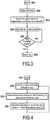
- Fig. 3 shows a flow chart of the procedure for determining a threshold ⁇ V T according to an embodiment of the present disclosure.
- the procedure of fig. 3 is preferably started together with the procedure of fig. 2 and more preferably its steps S21 to S24 are carried out in step S11 of the procedure of fig. 2 .
- step S22 SOC (state of charge) data of the battery are determined.
- the SOC sensor 9 may be used, as described above.
- step S23 the threshold ⁇ V T is determined based on the determined SOC and the currently determined degradation ⁇ x of the battery. The determination of ⁇ x is described in detail below in context of fig. 4 .
- step S24 the determined threshold ⁇ V T is set as threshold, as used in step S16 of fig. 2 .
- step S25 it is monitored whether charging has been stopped finally, what corresponds to step S18 in fig. 2 . If this is the case, the threshold ⁇ V T is reset in step S26. Accordingly, at each charging procedure (which may comprise several cycles of the procedure of fig. 2 ) the threshold ⁇ V T is set once in the beginning. Consequently for a subsequent charging procedure the threshold ⁇ V T is newly determined, so that the current degradation ⁇ x of the battery and the current SOC can be considered, when the subsequent charging procedure is started.
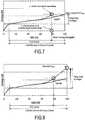
- Fig. 4 shows a flow chart of the procedure for determining the degradation ⁇ x of a battery according to an embodiment of the present disclosure. This procedure is preferably carried out in or before step S23 of fig. 3 , so that the threshold ⁇ V T is always determined based on a currently updated degradation ⁇ x . In this context it is also noted that the determined degradation ⁇ x rather represents an estimation of the actual degradation of the battery.
- step S32 temperature data of battery are obtained.
- the temperature sensor 8 may be used.
- these data may include not only the current temperature of the battery, but also historic temperature data since the last time the procedure of fig. 4 has been carried out, in particular since the last time the temperature frequency distribution T x has been updated (cf. step S33).
- step S33 the temperature frequency distribution T x is established or, in case a temperature frequency distribution T x already exists, it is updated.
- the collected temperature data obtained in step S32 are accumulated, wherein the accumulated time for each measured temperature is expressed as its inverse, i.e. as frequency.
- the temperature frequency distribution T x is described in more detail below in context of fig. 6 .
- step S34 the degradation ⁇ x of the battery is determined based on the temperature frequency distribution T x and the predetermined battery-type specific degradation rate ⁇ . This determination, i.e. calculation, is described in the following with reference to fig. 5 and 6 .
- the values for the temperature T and for the time t can thereby be derived from the temperature frequency distribution T x as shown in fig. 6 .
- the further parameters c and b are predetermined in context of the determination of the degradation rate ⁇ .
- k, A, Ea and R are known by pre-experiment of the specific battery type of the used battery or are generally known parameters.
- k ⁇ : ln ⁇ ln A ⁇ E R ⁇ 1 T
- the resulting diagram of the degradation rate ⁇ is shown in fig. 5 .
- the degradation rate ⁇ is predetermined and specific for the battery-type of the used battery.
- the degradation rate ⁇ is preferably determined in pre-experiment and is known by the battery (in case of a smart battery) and/or by the control device.
- the threshold ⁇ V T is preferably mapped to the determined degradation ⁇ x in a look-up map, i.e.:
- This relation between ⁇ V T and ⁇ x is preferably determined in a pre-experiment and is specific for the battery-type of the used battery.
- the look-up map may be stored in a data storage of the control-device or of the battery (in case of a smart battery).
- the determined SOC of the battery is considered when determining ⁇ V T .
- the control device may also have information regarding the relationship between SOC and ⁇ V T such as in the above-mentioned look-up map of ⁇ x. For example in said look-up map an additional column for SOC values may be added.
- Fig. 5 shows an exemplary and schematic diagram of a predetermined degradation rate in relation to the temperature of a battery.
- the values of the parameters b and c can be directly derived from this diagram, as b is the slope of the linear function and c is the intercept of the (elongated) linear function with the Y-axis.
- Fig. 6 shows an exemplary and schematic diagram of a determined temperature / frequency distribution of a battery.
- the x-axis represents the temperature T of the battery and the y-axis represents the frequency, i.e. the inverse of the time.
- the diagram contains the accumulated temperature data of the battery over its whole life time, i.e. over the whole time the battery has been used and the rest times between the usages.
- it is determined for each temperature the battery had during its life time, e.g. from -40°C to + 60°C in (quantized) steps of 1°C, how much time the battery had each of these temperatures.
- the accumulated time is thereby expressed by its inverse, i.e. by a frequency.
- Fig. 7 shows an exemplary and schematic voltage - SOC diagram of a battery, when a conventional charging control is applied.
- V x of the battery increases during charging, i.e. it increases with an increasing SOC of the battery.
- the continuous line thereby represents a battery without any degradation, e.g. a new battery.
- the measured voltage V x of such a battery reaches during charging the upper voltage limit V max , when the SOC reaches 100%. As an effect, it is correctly determined that charging is completed and charging is stopped.
- the dashed line represents a battery with lamination degradation, e.g. a used battery.
- the measured voltage V x of such a battery increases more strongly during charging due to the higher resistance caused by the lamination degradation.
- the voltage V x therefore reaches already the upper voltage limit V max , when the SOC is about 80%.
- V max the upper voltage limit
- Fig. 8 shows an exemplary and schematic voltage - SOC diagram of a battery, when a charging control according to an embodiment of the present disclosure is applied.
- Fig. 8 illustrates the same case as fig. 7 , i.e. a (new) battery without any degradation and a (used) battery having a lamination degradation. Both curves increase until they reach the initial upper voltage limit V max .
- the dashed line representing a battery with lamination degradation thereby reaches the initial upper voltage limit V max , when the SOC is about 80%.
- the upper voltage limit V max is increased and charging is continued. By repeating this procedure, until ⁇ V x does not exceed any more the threshold ⁇ V T , charging can be continued until the battery has a SOC of 100%.
- the extended upper voltage limit V max should still be limited such that any actually dangerous overvoltage can be avoided.
Landscapes
- Engineering & Computer Science (AREA)
- Power Engineering (AREA)
- Life Sciences & Earth Sciences (AREA)
- Sustainable Development (AREA)
- Sustainable Energy (AREA)
- Transportation (AREA)
- Mechanical Engineering (AREA)
- Physics & Mathematics (AREA)
- General Physics & Mathematics (AREA)
- Chemical & Material Sciences (AREA)
- Chemical Kinetics & Catalysis (AREA)
- Electrochemistry (AREA)
- General Chemical & Material Sciences (AREA)
- Manufacturing & Machinery (AREA)
- Secondary Cells (AREA)
- Tests Of Electric Status Of Batteries (AREA)
- Charge And Discharge Circuits For Batteries Or The Like (AREA)
Claims (14)
- Dispositif de commande (6) destiné à commander une charge d'une batterie rechargeable (2),
le dispositif de commande (6) étant configuré pour :déterminer la tension (Vx) de la batterie pendant la charge de la batterie,arrêter la charge, quand la tension déterminée (Vx) dépasse une limite de tension supérieure prédéterminée (Vmax),déterminer la tension (Vx) de la batterie après l'arrêt de la charge, caractérisé en ce quele dispositif de commande (6) est en outre configuré pour :déterminer la différence de tension (ΔVx) entre la limite de tension supérieure prédéterminée (Vmax) et la tension déterminée de la batterie après l'arrêt de la charge, etcontinuer à charger, quand la différence de tension déterminée (ΔVx) dépasse un seuil prédéterminé (ΔVT),déterminer le seuil (ΔVT) sur la base de l'état de charge (SOC) de la batterie avant de commencer la charge et/ou sur la base d'une dégradation déterminée (αx) de la batterie. - Dispositif de commande (6) selon la revendication 1, configuré en outre pour :quand la différence de tension déterminée (ΔVx) dépasse le seuil prédéterminé (ΔVT),augmenter la limite de tension supérieure prédéterminée (Vmax) d'un incrément de tension prédéterminé et redémarrer la charge de la batterie, ou bienredémarrer la charge de la batterie pour un intervalle de temps limité et déterminer à nouveau la différence de tension (ΔVx) après l'arrêt de la charge.
- Dispositif de commande (6) selon l'une quelconque des revendications 1 ou 2, configuré en outre pour :quand la différence de tension déterminée (ΔVx) ne dépasse pas le seuil prédéterminé (ΔVT),déterminer que la batterie est complètement chargée.
- Dispositif de commande (6) selon l'une quelconque des revendications précédentes, configuré en outre pour déterminer la dégradation (αx) de la batterie sur la base d'une distribution de température/fréquence de la batterie et d'un taux de dégradation prédéterminé (β) de la batterie, dans lequel la détermination de la dégradation (αx) de la batterie est plus particulièrement basée sur l'équation d'Arrhenius.
- Dispositif de commande (6) selon l'une quelconque des revendications précédentes, configuré en outre pour déterminer la distribution de température/fréquence de la batterie sur la base d'un enregistrement pour chaque température de la batterie de combien de temps la batterie a eu cette température pendant sa durée de vie.
- Dispositif de commande (6) selon l'une quelconque des revendications précédentes, comprenant : un capteur de tension (10) destiné à déterminer la tension (Vx) de la batterie, et/ou
un capteur de température (8) destiné à déterminer la température (T) de la batterie. - Bloc de batterie comprenant :au moins une batterie (2), en particulier une batterie bipolaire à l'état solide, etun dispositif de commande (6) selon l'une quelconque des revendications précédentes.
- Système de charge de batterie comprenant :au moins une batterie (2), en particulier une batterie bipolaire à l'état solide,un dispositif de charge (5) pour la batterie (2), etun dispositif de commande (6) selon l'une quelconque des revendications 1 à 6.
- Véhicule (1) comprenant :un moteur électrique (4), etun bloc de batterie selon la revendication 7, ou bienle véhicule (1) comprenant :un moteur électrique (4),au moins une batterie (2), en particulier une batterie bipolaire à l'état solide, etun dispositif de commande (6) selon l'une quelconque des revendications 1 à 6.
- Procédé de commande d'une charge d'une batterie rechargeable (2), comprenant les étapes de :détermination de la tension (Vx) de la batterie pendant la charge de la batterie,arrêt de la charge, quand la tension déterminée (Vx) dépasse une limite de tension supérieure prédéterminée (Vmax),détermination de la tension (Vx) de la batterie après l'arrêt de la charge, caractérisé en ce qu'il comprend des étapes supplémentaires de :détermination de la différence de tension (ΔVx) entre la limite de tension supérieure prédéterminée (Vmax) et la tension déterminée de la batterie après l'arrêt de la charge, etpoursuite de la charge, quand la différence de tension déterminée (ΔVx) dépasse un seuil prédéterminé (ΔVT),selon lequel le seuil (ΔVT) est déterminé sur la base de l'état de charge (SOC) de la batterie avant de commencer la charge et/ou sur la base d'une dégradation déterminée (αx) de la batterie.
- Procédé selon la revendication 10, comprenant en outre les étapes de :quand la différence de tension déterminée (ΔVx) dépasse le seuil prédéterminé (ΔVT),augmentation de la limite de tension supérieure prédéterminée (Vmax) d'un incrément de tension prédéterminé et redémarrage de la charge de la batterie, ou bienredémarrage de la charge de la batterie pour un intervalle de temps limité et détermination à nouveau de la différence de tension (ΔVx) après l'arrêt de la charge.
- Procédé selon l'une quelconque des revendications précédentes 10 à 11, comprenant en outre les étapes de :quand la différence de tension déterminée (ΔVx) ne dépasse pas le seuil prédéterminé (ΔVT),détermination que la batterie est complètement chargée.
- Procédé selon l'une quelconque des revendications précédentes 10 à 12, selon lequel la dégradation (αx) de la batterie est déterminée sur la base d'une distribution de température/fréquence de la batterie et d'un taux de dégradation prédéterminé (β) de la batterie,
la détermination de la dégradation (αx) de la batterie étant plus particulièrement basée sur l'équation d'Arrhenius. - Procédé selon la revendication précédente, selon lequel la distribution de température/fréquence de la batterie est déterminée sur la base d'un enregistrement pour chaque température de la batterie de combien de temps la batterie a eu cette température pendant sa durée de vie.
Applications Claiming Priority (1)
| Application Number | Priority Date | Filing Date | Title |
|---|---|---|---|
| PCT/EP2016/051987 WO2017129264A1 (fr) | 2016-01-29 | 2016-01-29 | Dispositif de commande et procédé de charge d'une batterie rechargeable |
Publications (2)
| Publication Number | Publication Date |
|---|---|
| EP3408128A1 EP3408128A1 (fr) | 2018-12-05 |
| EP3408128B1 true EP3408128B1 (fr) | 2020-09-02 |
Family
ID=55273266
Family Applications (1)
| Application Number | Title | Priority Date | Filing Date |
|---|---|---|---|
| EP16702404.1A Not-in-force EP3408128B1 (fr) | 2016-01-29 | 2016-01-29 | Dispositif de commande et procédé de charge d'une batterie rechargeable |
Country Status (5)
| Country | Link |
|---|---|
| US (1) | US10903669B2 (fr) |
| EP (1) | EP3408128B1 (fr) |
| JP (1) | JP6738901B2 (fr) |
| CN (1) | CN108602446B (fr) |
| WO (1) | WO2017129264A1 (fr) |
Families Citing this family (7)
| Publication number | Priority date | Publication date | Assignee | Title |
|---|---|---|---|---|
| US20200020991A1 (en) * | 2017-03-31 | 2020-01-16 | Toyota Motor Europe | System and method for charge protection of a lithium-ion battery |
| US11239680B2 (en) * | 2018-06-01 | 2022-02-01 | Texas Instruments Incorporated | Battery charger |
| CN113126732B (zh) * | 2020-01-15 | 2024-03-08 | 戴尔产品有限公司 | 电力备用设备充电系统 |
| TWI762372B (zh) * | 2021-07-06 | 2022-04-21 | 大陸商美律電子(深圳)有限公司 | 儲能裝置及其電源供應方法 |
| CN115675088B (zh) * | 2022-11-15 | 2024-11-08 | 湖北亿纬动力有限公司 | 低压电池的补电控制方法、装置、整车系统及存储介质 |
| CN119070407A (zh) * | 2023-05-30 | 2024-12-03 | 联想(北京)有限公司 | 电源电路、电子设备以及控制方法 |
| JP7779301B2 (ja) * | 2023-08-22 | 2025-12-03 | トヨタ自動車株式会社 | 電池評価システム |
Family Cites Families (15)
| Publication number | Priority date | Publication date | Assignee | Title |
|---|---|---|---|---|
| JP2000023384A (ja) | 1998-06-30 | 2000-01-21 | Matsushita Electric Ind Co Ltd | 充電装置 |
| SE519958C2 (sv) | 2001-09-20 | 2003-04-29 | Nilar Europ Ab | Ett bipolärt batteri och en biplåtsammansättning |
| JP2004171955A (ja) * | 2002-11-20 | 2004-06-17 | Nissan Motor Co Ltd | バイポーラ電池、該バイポーラ電池を複数接続した組電池、該バイポーラ電池または該組電池の充電を制御する充電制御システム、該バイポーラ電池、該組電池または該充電システムを搭載した車両 |
| JP2004282881A (ja) | 2003-03-14 | 2004-10-07 | Mitsumi Electric Co Ltd | 二次電池の充電装置および充電方法 |
| JP5289083B2 (ja) * | 2009-02-05 | 2013-09-11 | 三洋電機株式会社 | 二次電池の異常検出装置および二次電池装置 |
| JP4852630B2 (ja) | 2009-06-25 | 2012-01-11 | 本田技研工業株式会社 | バッテリ充放電制御装置 |
| JP4744622B2 (ja) * | 2009-07-01 | 2011-08-10 | トヨタ自動車株式会社 | 車両の制御装置 |
| JP5160523B2 (ja) | 2009-11-04 | 2013-03-13 | 本田技研工業株式会社 | 電気自動車 |
| JP5438602B2 (ja) * | 2010-06-16 | 2014-03-12 | 株式会社日立製作所 | 充電制御システム |
| WO2012043744A1 (fr) * | 2010-09-29 | 2012-04-05 | 三洋電機株式会社 | Dispositif de commande de charge |
| JP5691365B2 (ja) | 2010-10-07 | 2015-04-01 | ソニー株式会社 | 電力制御装置、電力制御方法、および給電システム |
| WO2013021446A1 (fr) * | 2011-08-08 | 2013-02-14 | トヨタ自動車株式会社 | Véhicule, procédé de commande de véhicule et dispositif de commande de véhicule |
| JP6214131B2 (ja) | 2012-02-21 | 2017-10-18 | 株式会社Nttファシリティーズ | 組電池充電システムおよび組電池充電方法 |
| JP5904050B2 (ja) * | 2012-08-03 | 2016-04-13 | ソニー株式会社 | 電力貯蔵装置 |
| JP6308301B2 (ja) * | 2014-08-29 | 2018-04-18 | 日産自動車株式会社 | 二次電池充電システム及び充電方法 |
-
2016
- 2016-01-29 EP EP16702404.1A patent/EP3408128B1/fr not_active Not-in-force
- 2016-01-29 US US16/070,197 patent/US10903669B2/en active Active
- 2016-01-29 WO PCT/EP2016/051987 patent/WO2017129264A1/fr not_active Ceased
- 2016-01-29 JP JP2018539384A patent/JP6738901B2/ja active Active
- 2016-01-29 CN CN201680080296.XA patent/CN108602446B/zh active Active
Non-Patent Citations (1)
| Title |
|---|
| None * |
Also Published As
| Publication number | Publication date |
|---|---|
| JP2019506829A (ja) | 2019-03-07 |
| US10903669B2 (en) | 2021-01-26 |
| CN108602446A (zh) | 2018-09-28 |
| WO2017129264A1 (fr) | 2017-08-03 |
| EP3408128A1 (fr) | 2018-12-05 |
| CN108602446B (zh) | 2022-03-01 |
| JP6738901B2 (ja) | 2020-08-12 |
| US20190023145A1 (en) | 2019-01-24 |
Similar Documents
| Publication | Publication Date | Title |
|---|---|---|
| EP3408128B1 (fr) | Dispositif de commande et procédé de charge d'une batterie rechargeable | |
| EP3411262B1 (fr) | Dispositif de commande et procédé permettant de charger une batterie rechargeable | |
| EP3408129B1 (fr) | Dispositif et procédé de commande pour décharger une batterie rechargeable | |
| EP3411261B1 (fr) | Dispositif de commande et procédé de décharge d'une batterie rechargeable | |
| JP6656396B2 (ja) | 蓄電池充電のための制御装置および蓄電池を充電する方法 | |
| JP4530078B2 (ja) | 蓄電制御装置及び車両 | |
| EP4156448B1 (fr) | Dispositif de commande de batterie de stockage, système de stockage d'énergie et procédé de commande de batterie de stockage | |
| US20250183694A1 (en) | In-vehicle backup control device | |
| CN119550870B (zh) | 一种车辆动力电池预充电的方法、装置、车辆和存储介质 |
Legal Events
| Date | Code | Title | Description |
|---|---|---|---|
| STAA | Information on the status of an ep patent application or granted ep patent |
Free format text: STATUS: THE INTERNATIONAL PUBLICATION HAS BEEN MADE |
|
| PUAI | Public reference made under article 153(3) epc to a published international application that has entered the european phase |
Free format text: ORIGINAL CODE: 0009012 |
|
| STAA | Information on the status of an ep patent application or granted ep patent |
Free format text: STATUS: REQUEST FOR EXAMINATION WAS MADE |
|
| 17P | Request for examination filed |
Effective date: 20180824 |
|
| AK | Designated contracting states |
Kind code of ref document: A1 Designated state(s): AL AT BE BG CH CY CZ DE DK EE ES FI FR GB GR HR HU IE IS IT LI LT LU LV MC MK MT NL NO PL PT RO RS SE SI SK SM TR |
|
| AX | Request for extension of the european patent |
Extension state: BA ME |
|
| RIN1 | Information on inventor provided before grant (corrected) |
Inventor name: KATOH, YUKI Inventor name: KOMIYAMA, KEITA |
|
| DAV | Request for validation of the european patent (deleted) | ||
| DAX | Request for extension of the european patent (deleted) | ||
| STAA | Information on the status of an ep patent application or granted ep patent |
Free format text: STATUS: EXAMINATION IS IN PROGRESS |
|
| 17Q | First examination report despatched |
Effective date: 20190527 |
|
| REG | Reference to a national code |
Ref country code: DE Ref legal event code: R079 Ref document number: 602016043129 Country of ref document: DE Free format text: PREVIOUS MAIN CLASS: B60L0011180000 Ipc: G01R0031360000 |
|
| RIC1 | Information provided on ipc code assigned before grant |
Ipc: H01M 10/42 20060101ALI20190816BHEP Ipc: G01R 19/165 20060101ALI20190816BHEP Ipc: B60L 58/12 20190101ALI20190816BHEP Ipc: H02J 7/04 20060101ALI20190816BHEP Ipc: B60L 58/10 20190101ALI20190816BHEP Ipc: H02J 7/00 20060101ALI20190816BHEP Ipc: G01R 31/36 20190101AFI20190816BHEP Ipc: H01M 10/48 20060101ALI20190816BHEP |
|
| GRAP | Despatch of communication of intention to grant a patent |
Free format text: ORIGINAL CODE: EPIDOSNIGR1 |
|
| STAA | Information on the status of an ep patent application or granted ep patent |
Free format text: STATUS: GRANT OF PATENT IS INTENDED |
|
| INTG | Intention to grant announced |
Effective date: 20191017 |
|
| RIN1 | Information on inventor provided before grant (corrected) |
Inventor name: KATOH, YUKI Inventor name: KOMIYAMA, KEITA |
|
| GRAS | Grant fee paid |
Free format text: ORIGINAL CODE: EPIDOSNIGR3 |
|
| GRAJ | Information related to disapproval of communication of intention to grant by the applicant or resumption of examination proceedings by the epo deleted |
Free format text: ORIGINAL CODE: EPIDOSDIGR1 |
|
| GRAL | Information related to payment of fee for publishing/printing deleted |
Free format text: ORIGINAL CODE: EPIDOSDIGR3 |
|
| STAA | Information on the status of an ep patent application or granted ep patent |
Free format text: STATUS: EXAMINATION IS IN PROGRESS |
|
| INTC | Intention to grant announced (deleted) | ||
| GRAR | Information related to intention to grant a patent recorded |
Free format text: ORIGINAL CODE: EPIDOSNIGR71 |
|
| STAA | Information on the status of an ep patent application or granted ep patent |
Free format text: STATUS: GRANT OF PATENT IS INTENDED |
|
| GRAA | (expected) grant |
Free format text: ORIGINAL CODE: 0009210 |
|
| STAA | Information on the status of an ep patent application or granted ep patent |
Free format text: STATUS: THE PATENT HAS BEEN GRANTED |
|
| INTG | Intention to grant announced |
Effective date: 20200723 |
|
| AK | Designated contracting states |
Kind code of ref document: B1 Designated state(s): AL AT BE BG CH CY CZ DE DK EE ES FI FR GB GR HR HU IE IS IT LI LT LU LV MC MK MT NL NO PL PT RO RS SE SI SK SM TR |
|
| REG | Reference to a national code |
Ref country code: GB Ref legal event code: FG4D |
|
| REG | Reference to a national code |
Ref country code: AT Ref legal event code: REF Ref document number: 1309464 Country of ref document: AT Kind code of ref document: T Effective date: 20200915 Ref country code: CH Ref legal event code: EP |
|
| REG | Reference to a national code |
Ref country code: DE Ref legal event code: R096 Ref document number: 602016043129 Country of ref document: DE |
|
| REG | Reference to a national code |
Ref country code: IE Ref legal event code: FG4D |
|
| REG | Reference to a national code |
Ref country code: DE Ref legal event code: R081 Ref document number: 602016043129 Country of ref document: DE Owner name: TOYOTA JIDOSHA KABUSHIKI KAISHA, TOYOTA-SHI, JP Free format text: FORMER OWNER: TOYOTA MOTOR EUROPE, BRUSSELS, BE |
|
| RAP2 | Party data changed (patent owner data changed or rights of a patent transferred) |
Owner name: TOYOTA JIDOSHA KABUSHIKI KAISHA |
|
| REG | Reference to a national code |
Ref country code: GB Ref legal event code: 732E Free format text: REGISTERED BETWEEN 20201203 AND 20201209 |
|
| REG | Reference to a national code |
Ref country code: LT Ref legal event code: MG4D |
|
| PG25 | Lapsed in a contracting state [announced via postgrant information from national office to epo] |
Ref country code: HR Free format text: LAPSE BECAUSE OF FAILURE TO SUBMIT A TRANSLATION OF THE DESCRIPTION OR TO PAY THE FEE WITHIN THE PRESCRIBED TIME-LIMIT Effective date: 20200902 Ref country code: SE Free format text: LAPSE BECAUSE OF FAILURE TO SUBMIT A TRANSLATION OF THE DESCRIPTION OR TO PAY THE FEE WITHIN THE PRESCRIBED TIME-LIMIT Effective date: 20200902 Ref country code: GR Free format text: LAPSE BECAUSE OF FAILURE TO SUBMIT A TRANSLATION OF THE DESCRIPTION OR TO PAY THE FEE WITHIN THE PRESCRIBED TIME-LIMIT Effective date: 20201203 Ref country code: NO Free format text: LAPSE BECAUSE OF FAILURE TO SUBMIT A TRANSLATION OF THE DESCRIPTION OR TO PAY THE FEE WITHIN THE PRESCRIBED TIME-LIMIT Effective date: 20201202 Ref country code: BG Free format text: LAPSE BECAUSE OF FAILURE TO SUBMIT A TRANSLATION OF THE DESCRIPTION OR TO PAY THE FEE WITHIN THE PRESCRIBED TIME-LIMIT Effective date: 20201202 Ref country code: FI Free format text: LAPSE BECAUSE OF FAILURE TO SUBMIT A TRANSLATION OF THE DESCRIPTION OR TO PAY THE FEE WITHIN THE PRESCRIBED TIME-LIMIT Effective date: 20200902 Ref country code: LT Free format text: LAPSE BECAUSE OF FAILURE TO SUBMIT A TRANSLATION OF THE DESCRIPTION OR TO PAY THE FEE WITHIN THE PRESCRIBED TIME-LIMIT Effective date: 20200902 |
|
| REG | Reference to a national code |
Ref country code: NL Ref legal event code: MP Effective date: 20200902 |
|
| REG | Reference to a national code |
Ref country code: AT Ref legal event code: MK05 Ref document number: 1309464 Country of ref document: AT Kind code of ref document: T Effective date: 20200902 |
|
| PG25 | Lapsed in a contracting state [announced via postgrant information from national office to epo] |
Ref country code: LV Free format text: LAPSE BECAUSE OF FAILURE TO SUBMIT A TRANSLATION OF THE DESCRIPTION OR TO PAY THE FEE WITHIN THE PRESCRIBED TIME-LIMIT Effective date: 20200902 Ref country code: RS Free format text: LAPSE BECAUSE OF FAILURE TO SUBMIT A TRANSLATION OF THE DESCRIPTION OR TO PAY THE FEE WITHIN THE PRESCRIBED TIME-LIMIT Effective date: 20200902 Ref country code: PL Free format text: LAPSE BECAUSE OF FAILURE TO SUBMIT A TRANSLATION OF THE DESCRIPTION OR TO PAY THE FEE WITHIN THE PRESCRIBED TIME-LIMIT Effective date: 20200902 |
|
| PG25 | Lapsed in a contracting state [announced via postgrant information from national office to epo] |
Ref country code: CZ Free format text: LAPSE BECAUSE OF FAILURE TO SUBMIT A TRANSLATION OF THE DESCRIPTION OR TO PAY THE FEE WITHIN THE PRESCRIBED TIME-LIMIT Effective date: 20200902 Ref country code: RO Free format text: LAPSE BECAUSE OF FAILURE TO SUBMIT A TRANSLATION OF THE DESCRIPTION OR TO PAY THE FEE WITHIN THE PRESCRIBED TIME-LIMIT Effective date: 20200902 Ref country code: SM Free format text: LAPSE BECAUSE OF FAILURE TO SUBMIT A TRANSLATION OF THE DESCRIPTION OR TO PAY THE FEE WITHIN THE PRESCRIBED TIME-LIMIT Effective date: 20200902 Ref country code: PT Free format text: LAPSE BECAUSE OF FAILURE TO SUBMIT A TRANSLATION OF THE DESCRIPTION OR TO PAY THE FEE WITHIN THE PRESCRIBED TIME-LIMIT Effective date: 20210104 Ref country code: EE Free format text: LAPSE BECAUSE OF FAILURE TO SUBMIT A TRANSLATION OF THE DESCRIPTION OR TO PAY THE FEE WITHIN THE PRESCRIBED TIME-LIMIT Effective date: 20200902 |
|
| PG25 | Lapsed in a contracting state [announced via postgrant information from national office to epo] |
Ref country code: ES Free format text: LAPSE BECAUSE OF FAILURE TO SUBMIT A TRANSLATION OF THE DESCRIPTION OR TO PAY THE FEE WITHIN THE PRESCRIBED TIME-LIMIT Effective date: 20200902 Ref country code: AL Free format text: LAPSE BECAUSE OF FAILURE TO SUBMIT A TRANSLATION OF THE DESCRIPTION OR TO PAY THE FEE WITHIN THE PRESCRIBED TIME-LIMIT Effective date: 20200902 Ref country code: AT Free format text: LAPSE BECAUSE OF FAILURE TO SUBMIT A TRANSLATION OF THE DESCRIPTION OR TO PAY THE FEE WITHIN THE PRESCRIBED TIME-LIMIT Effective date: 20200902 Ref country code: IS Free format text: LAPSE BECAUSE OF FAILURE TO SUBMIT A TRANSLATION OF THE DESCRIPTION OR TO PAY THE FEE WITHIN THE PRESCRIBED TIME-LIMIT Effective date: 20210102 |
|
| REG | Reference to a national code |
Ref country code: DE Ref legal event code: R097 Ref document number: 602016043129 Country of ref document: DE |
|
| PG25 | Lapsed in a contracting state [announced via postgrant information from national office to epo] |
Ref country code: SK Free format text: LAPSE BECAUSE OF FAILURE TO SUBMIT A TRANSLATION OF THE DESCRIPTION OR TO PAY THE FEE WITHIN THE PRESCRIBED TIME-LIMIT Effective date: 20200902 |
|
| PLBE | No opposition filed within time limit |
Free format text: ORIGINAL CODE: 0009261 |
|
| STAA | Information on the status of an ep patent application or granted ep patent |
Free format text: STATUS: NO OPPOSITION FILED WITHIN TIME LIMIT |
|
| 26N | No opposition filed |
Effective date: 20210603 |
|
| PG25 | Lapsed in a contracting state [announced via postgrant information from national office to epo] |
Ref country code: SI Free format text: LAPSE BECAUSE OF FAILURE TO SUBMIT A TRANSLATION OF THE DESCRIPTION OR TO PAY THE FEE WITHIN THE PRESCRIBED TIME-LIMIT Effective date: 20200902 Ref country code: DK Free format text: LAPSE BECAUSE OF FAILURE TO SUBMIT A TRANSLATION OF THE DESCRIPTION OR TO PAY THE FEE WITHIN THE PRESCRIBED TIME-LIMIT Effective date: 20200902 Ref country code: MC Free format text: LAPSE BECAUSE OF FAILURE TO SUBMIT A TRANSLATION OF THE DESCRIPTION OR TO PAY THE FEE WITHIN THE PRESCRIBED TIME-LIMIT Effective date: 20200902 |
|
| REG | Reference to a national code |
Ref country code: CH Ref legal event code: PL |
|
| PG25 | Lapsed in a contracting state [announced via postgrant information from national office to epo] |
Ref country code: LU Free format text: LAPSE BECAUSE OF NON-PAYMENT OF DUE FEES Effective date: 20210129 |
|
| REG | Reference to a national code |
Ref country code: BE Ref legal event code: MM Effective date: 20210131 |
|
| PG25 | Lapsed in a contracting state [announced via postgrant information from national office to epo] |
Ref country code: IT Free format text: LAPSE BECAUSE OF FAILURE TO SUBMIT A TRANSLATION OF THE DESCRIPTION OR TO PAY THE FEE WITHIN THE PRESCRIBED TIME-LIMIT Effective date: 20200902 |
|
| PG25 | Lapsed in a contracting state [announced via postgrant information from national office to epo] |
Ref country code: LI Free format text: LAPSE BECAUSE OF NON-PAYMENT OF DUE FEES Effective date: 20210131 Ref country code: CH Free format text: LAPSE BECAUSE OF NON-PAYMENT OF DUE FEES Effective date: 20210131 |
|
| PG25 | Lapsed in a contracting state [announced via postgrant information from national office to epo] |
Ref country code: IE Free format text: LAPSE BECAUSE OF NON-PAYMENT OF DUE FEES Effective date: 20210129 |
|
| PGFP | Annual fee paid to national office [announced via postgrant information from national office to epo] |
Ref country code: GB Payment date: 20220120 Year of fee payment: 7 Ref country code: DE Payment date: 20220114 Year of fee payment: 7 |
|
| PGFP | Annual fee paid to national office [announced via postgrant information from national office to epo] |
Ref country code: FR Payment date: 20220121 Year of fee payment: 7 |
|
| PG25 | Lapsed in a contracting state [announced via postgrant information from national office to epo] |
Ref country code: BE Free format text: LAPSE BECAUSE OF NON-PAYMENT OF DUE FEES Effective date: 20210131 |
|
| PG25 | Lapsed in a contracting state [announced via postgrant information from national office to epo] |
Ref country code: NL Free format text: LAPSE BECAUSE OF NON-PAYMENT OF DUE FEES Effective date: 20200923 Ref country code: CY Free format text: LAPSE BECAUSE OF FAILURE TO SUBMIT A TRANSLATION OF THE DESCRIPTION OR TO PAY THE FEE WITHIN THE PRESCRIBED TIME-LIMIT Effective date: 20200902 |
|
| PG25 | Lapsed in a contracting state [announced via postgrant information from national office to epo] |
Ref country code: HU Free format text: LAPSE BECAUSE OF FAILURE TO SUBMIT A TRANSLATION OF THE DESCRIPTION OR TO PAY THE FEE WITHIN THE PRESCRIBED TIME-LIMIT; INVALID AB INITIO Effective date: 20160129 |
|
| REG | Reference to a national code |
Ref country code: DE Ref legal event code: R119 Ref document number: 602016043129 Country of ref document: DE |
|
| GBPC | Gb: european patent ceased through non-payment of renewal fee |
Effective date: 20230129 |
|
| PG25 | Lapsed in a contracting state [announced via postgrant information from national office to epo] |
Ref country code: GB Free format text: LAPSE BECAUSE OF NON-PAYMENT OF DUE FEES Effective date: 20230129 Ref country code: DE Free format text: LAPSE BECAUSE OF NON-PAYMENT OF DUE FEES Effective date: 20230801 |
|
| PG25 | Lapsed in a contracting state [announced via postgrant information from national office to epo] |
Ref country code: FR Free format text: LAPSE BECAUSE OF NON-PAYMENT OF DUE FEES Effective date: 20230131 |
|
| PG25 | Lapsed in a contracting state [announced via postgrant information from national office to epo] |
Ref country code: MK Free format text: LAPSE BECAUSE OF FAILURE TO SUBMIT A TRANSLATION OF THE DESCRIPTION OR TO PAY THE FEE WITHIN THE PRESCRIBED TIME-LIMIT Effective date: 20200902 |
|
| PG25 | Lapsed in a contracting state [announced via postgrant information from national office to epo] |
Ref country code: MT Free format text: LAPSE BECAUSE OF FAILURE TO SUBMIT A TRANSLATION OF THE DESCRIPTION OR TO PAY THE FEE WITHIN THE PRESCRIBED TIME-LIMIT Effective date: 20200902 |
|
| PG25 | Lapsed in a contracting state [announced via postgrant information from national office to epo] |
Ref country code: TR Free format text: LAPSE BECAUSE OF FAILURE TO SUBMIT A TRANSLATION OF THE DESCRIPTION OR TO PAY THE FEE WITHIN THE PRESCRIBED TIME-LIMIT Effective date: 20200902 |