EP3408204B1 - Verfahren und vorrichtung zur steuerung der bewegung in einem gewichtsausgleichssystem - Google Patents
Verfahren und vorrichtung zur steuerung der bewegung in einem gewichtsausgleichssystem Download PDFInfo
- Publication number
- EP3408204B1 EP3408204B1 EP17744983.2A EP17744983A EP3408204B1 EP 3408204 B1 EP3408204 B1 EP 3408204B1 EP 17744983 A EP17744983 A EP 17744983A EP 3408204 B1 EP3408204 B1 EP 3408204B1
- Authority
- EP
- European Patent Office
- Prior art keywords
- motor
- magnitude
- torque
- level
- position feedback
- Prior art date
- Legal status (The legal status is an assumption and is not a legal conclusion. Google has not performed a legal analysis and makes no representation as to the accuracy of the status listed.)
- Active
Links
Images




Classifications
-
- H—ELECTRICITY
- H02—GENERATION; CONVERSION OR DISTRIBUTION OF ELECTRIC POWER
- H02P—CONTROL OR REGULATION OF ELECTRIC MOTORS, ELECTRIC GENERATORS OR DYNAMO-ELECTRIC CONVERTERS; CONTROLLING TRANSFORMERS, REACTORS OR CHOKE COILS
- H02P1/00—Arrangements for starting electric motors or dynamo-electric converters
- H02P1/02—Details of starting control
- H02P1/028—Details of starting control wherein the motor voltage is increased at low speed, to start or restart high inertia loads
-
- B—PERFORMING OPERATIONS; TRANSPORTING
- B66—HOISTING; LIFTING; HAULING
- B66B—ELEVATORS; ESCALATORS OR MOVING WALKWAYS
- B66B1/00—Control systems of elevators in general
- B66B1/24—Control systems with regulation, i.e. with retroactive action, for influencing travelling speed, acceleration, or deceleration
- B66B1/28—Control systems with regulation, i.e. with retroactive action, for influencing travelling speed, acceleration, or deceleration electrical
- B66B1/30—Control systems with regulation, i.e. with retroactive action, for influencing travelling speed, acceleration, or deceleration electrical effective on driving gear, e.g. acting on power electronics, on inverter or rectifier controlled motor
- B66B1/304—Control systems with regulation, i.e. with retroactive action, for influencing travelling speed, acceleration, or deceleration electrical effective on driving gear, e.g. acting on power electronics, on inverter or rectifier controlled motor with starting torque control
-
- H—ELECTRICITY
- H02—GENERATION; CONVERSION OR DISTRIBUTION OF ELECTRIC POWER
- H02P—CONTROL OR REGULATION OF ELECTRIC MOTORS, ELECTRIC GENERATORS OR DYNAMO-ELECTRIC CONVERTERS; CONTROLLING TRANSFORMERS, REACTORS OR CHOKE COILS
- H02P23/00—Arrangements or methods for the control of AC motors characterised by a control method other than vector control
- H02P23/06—Controlling the motor in four quadrants
-
- B—PERFORMING OPERATIONS; TRANSPORTING
- B66—HOISTING; LIFTING; HAULING
- B66B—ELEVATORS; ESCALATORS OR MOVING WALKWAYS
- B66B2201/00—Aspects of control systems of elevators
Definitions
- the subject matter disclosed herein relates to a method and apparatus for controlling motion in a counterbalancing system and, more specifically, to a method and apparatus for determining a pre-torque direction during brake engagement and applying a pre-torque in the pre-torque direction prior to brake disengagement.
- Elevators are typically implemented as counterbalancing systems. Accordingly, cables (or ropes) are often provided around a sheave (a grooved spindle or pulley), mounted to the top of an elevator cab in order to raise or lower the cab within an elevator shaft. A first end of the cables may be mounted to a first point at the top of the shaft and routed down and around a sheave mounted to the top of the cab. The cables may then be routed over a sheave mounted to an electric motor with a drive shaft there between. The cables may then continue around one or more sheaves mounted to a counterweight, then back to a second point at the top of the shaft.
- a sheave a grooved spindle or pulley
- a brake is also typically used in conjunction with the motor.
- the motor when it is desired to remain stationary, the motor is typically enabled for zero speed, and while the motor is still enabled, the brake is enabled, and then the motor may be subsequently disabled while the brake is engaged to hold the sheave, cables, cab and counterweight stationary. Then, to resume motion, such as upon a call for the elevator to move to another floor, the motor is enabled for zero speed, then the brake is disengaged (or picked), then the motor continues to move the cab accordingly.
- the present inventors have recognized that certain braking systems, when used in a counterbalancing system, still allow a limited amount of movement in a direction opposite the direction that the sheave is being pulled.
- This limited amount of movement may allow for determining the direction that the sheave is being pulled by activating an electric motor, with the brake engaged, to apply torques in opposing directions. There will be no movement in the direction that the sheave is being pulled, but there will be a limited amount of movement measurable in a direction opposite the direction that the sheave is being pulled due to backlash.
- the limited amount of movement may be detected by an encoder, and the motor may then pre-apply a correct torque in the direction opposite the direction that the sheave is being pulled before releasing the brake to allow for a smoother transition.
- loads may vary with each ride or operation in either the ascending or descending direction based on the number of passengers in any given run.
- a motion controlling inverter may be provided with a proper level of pre-torque applied in the correct direction to provide a smooth, quieter, and more consistent start to a run, while interfacing with machine brakes and elevator controllers to hold a position until it is safe start movement.
- External load weighing devices may be eliminated in favor of techniques of the present invention, thereby reducing the cost of installation and/or calibration of such devices. Accordingly, aspects of the invention may provide the ability to determine both direction and magnitude of a lifting device without external weight measuring devices.
- primary motion for the counterbalanced lifting device such as an elevator
- a system with an electrical motor and a sheave Wire cables in grooves of the sheave may be connected to the passenger car at one end and a counterbalance at the other end.
- mechanical brakes may be mounted to the motor shaft or sheave.
- One or more brake disks may be splined onto a rotor shaft opposite the sheave.
- Such mechanical connection may provide for a small degree of movement between the rotor shaft and the brake which can be used while the brake is still holding the load to sense an offset in the load.
- Any motion on the machine shaft may be detected by one or more encoders which may be mechanically connected to the rotor.
- the brake may remain fixed while the machine is driven or controlled by an AC or DC drive, and the motion sensing encoder may be fed back to the AC or DC drive as a reference device for proper speed and position control.
- a lifting device When a lifting device is engaged for motion, a fixed amount of weight may be established for the individual run or motion profile. At this point the drive may be made ready to operate or enabled. Between a time when an enable signal is commanded by the elevator car controller and the brake is released to begin motion, a pre-torque direction and magnitude may be determined. This may be done so that the loading that is being held by the brake may be transferred to the rotor before the brake is released, thereby resulting in a smooth transition.
- gates and internal control may be active.
- a pulsed torque may be applied from the rotor prior to releasing the brake to sense any slight movement via the encoder feedback.
- An increasing level of torque may be applied to the rotor in the positive then the negative direction while monitoring for movement. If there is backlash between the rotor shaft and the brake, such that beyond a torque level the backlash is taken up and motion is sensed, then that may be the level that is maintained to hold the offset load when the brake is subsequently released. This may be done in both directions as the load offset could be in either.
- the application of torque before the brake is released may take up a load offset and avoid an audible and/or vibrational transient which may ordinarily occur.
- a sheave and rotor may be pulled one way by a load, and a small movement may be sensed if the rotor produces a torque higher but in the opposite direction to the load just as the rotor produced torque overcomes the load torque.
- varying a magnitude of the pre-torque pulse may allow for determining a magnitude for the pre-torque command in addition to a direction. With both direction and magnitude, the operation of the counterbalancing system can begin while providing a smooth start.
- a method of determining a desired pretorque level for a motor controlling motion in a counterbalancing system has a holding brake operatively connected to a drive shaft of the motor.
- a magnitude of current applied to the motor is increased to generate torque in a first direction of rotation while the holding brake is set, and a position feedback signal corresponding to rotation of the motor while the torque is generated in the first direction is monitored.
- the current applied to the motor to generate torque in the first direction of rotation is removed, and an increasing magnitude of current is applied to the motor to generate torque in a second direction of rotation while the holding brake is set.
- the position feedback signal corresponding to rotation of the motor while the torque is generated in the second direction is monitored.
- the current applied to the motor to generate torque in the second direction of rotation is removed, and the desired pretorque level is determined as a function of the magnitude of current applied to the motor and a magnitude of rotation detected by the position feedback signal.
- the step of determining the desired pretorque level may include comparing a change in the position feedback signal to a first threshold, and setting the desired pretorque level equal to the magnitude of current applied to the motor when the change in the position feedback signal reaches the first threshold.
- the step of determining the desired pretorque level may include comparing a change in the position feedback signal to a first threshold, monitoring the position feedback signal until the change in the position feedback signal drops back below the first threshold when the change in the position feedback signal exceeds the first threshold, and setting the desired pretorque level equal to the magnitude of current applied to the motor when the change in the position feedback signal drops back below the first threshold when the change in the position feedback signal drops back below the first threshold.
- a system for determining a desired pretorque level for a motor controlling motion in a counterbalancing system has a holding brake operatively connected to a drive shaft of the motor.
- the system includes a power converter, a position feedback device, and a controller.
- the power converter is operatively connected to the motor to supply a variable voltage and a variable current to the motor for controlling operation of the motor.
- the position feedback device is operatively connected to the motor and configured to generate a signal corresponding to an angular position of the motor.
- the controller includes an input operative to receive the signal from the position feedback device, a memory device operative to store a plurality of instructions, and a processor operative to execute the plurality of instructions.
- Thee processor executes the instructions to control operation of the power converter to provide an increasing magnitude of current to the motor with a first polarity and to monitor the signal from the position feedback device while the increasing magnitude of current with the first polarity is being provided to the motor, where the current increases from a first level to a second level and generates a torque in the motor in a first direction of rotation.
- the processor further executes to control operation of the power converter to provide a decreasing magnitude of current with the first polarity to the motor, where the current decreases from the second level to the first level.
- the power converter provides an increasing magnitude of current to the motor with a second polarity and monitors the signal from the position feedback device while the increasing magnitude of current with the second polarity is being provided to the motor, where the current increases from the first level to a third level, the second polarity is opposite the first polarity, and the current generates a torque in the motor in a second direction of rotation.
- the power converter provides a decreasing magnitude of current with the second polarity to the motor, where the current decreases from the third level to the first level, and determines the desired pretorque level as a function of the magnitude of current applied to the motor and a magnitude of rotation detected by the position feedback signal.
- the system may include a motor drive, where the power converter is a power conversion section of the motor drive and the controller is a control section of the motor drive.
- the desired pretorque level may be determined as a function of the magnitude of current applied to the motor as the current is increasing in magnitude or as the current is decreasing in magnitude.
- the processor may compare a change in the signal from the position feedback device to a first threshold.
- the processor may set the desired pretorque level equal to the magnitude of current applied to the motor when the change in the signal from the position feedback device reaches the first threshold.
- the processor may monitor the signal from the position feedback device until the change in the signal drops back below the first threshold when the change in the signal from the position feedback device exceeds the first threshold, and when the change in the signal from the position feedback device drops back below the first threshold, set the desired pretorque level equal to the magnitude of current applied to the motor when the change in the signal from the position feedback device drops back below the first threshold.
- a method of reducing rollback for a motor controlling motion in a counterbalancing system has a holding brake operatively connected to a drive shaft of the motor, and the rollback occurring when the brake is opened.
- the initial steps are performed with the holding brake set.
- the motor applies a first torque is applied to the drive shaft in a first direction, and a position feedback signal corresponding to rotation of the drive shaft while the first torque is being applied is monitored.
- the motor applies a second torque to the drive shaft in a second direction, and the position feedback signal corresponding to rotation of the drive shaft while the second torque is being applied is monitored.
- a magnitude and direction of a desired pretorque level is determined as a function of the applied first and second torque and of the position feedback signal.
- the motor applies a torque at the desired pretorque level to the drive shaft and the holding brake is released.
- a motor drive supplies a variable voltage and a variable current to the motor to apply each torque to the drive shaft, and the motor drive receives the position feedback signal and generates a control signal to release the holding brake.
- the step of activating the motor to apply the first torque may include the steps of incrementally changing a magnitude of current applied to the motor to generate the first torque from a first level to a second level, and removing the current applied to the motor to generate the first torque.
- the step of activating the motor to apply the second torque may include the steps of incrementally changing a magnitude of current applied to the motor to generate the second torque from a third level to a fourth level, and removing the current applied to the motor to generate the second torque.
- the desired pretorque level may be determined as a function of the magnitude of current applied to the drive shaft.
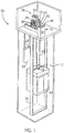
- a shaft 12 includes a cab 14 configured to move up and down the shaft 12.
- the cab 14 includes, for example, wheels configured to engage rails 16 extending vertically along each side of the shaft 12 to maintain horizontal alignment of the cab 14 within the shaft 12.
- Cables 20 extending around one or more cab sheaves 18 (a grooved spindle or pulley) mounted to the top of the cab 14 may be used to raise or lower the cab 14 within the shaft 12.
- a first end of the cables 20 are fixedly mounted to a first point at the top of the shaft 12 and routed down and around the cab sheave 18 mounted to the top of the cab 14.
- the cables 20 are then routed over one or more drive sheaves 78 mounted to an electrical motor 70.
- the cables 20 continue around one or more counterweight sheaves 32 mounted to a counterweight 30 and back to a second point at the top of the shaft 12. It is contemplated that various other configurations of cables, sheaves, and cable routing may be utilized according to the application requirements without deviating from the scope of the invention.
- the motor 70 may be mounted in a machine room located above the elevator shaft 12.
- the motor 70 may be mounted in the elevator shaft 12.
- a brake 60 is operatively connected to the motor 70 to provide braking in the system, and an encoder 80 is operatively connected to the motor 70 to provide a feedback signal corresponding to an angular position of the motor 70.
- a control cabinet 41 is provided in the machine room.
- the control cabinet 41 may include a motor drive 40 to control operation of the motor and a separate controller 73 providing instructions to the motor drive 40.
- a junction box 74 may be mounted to the top of a housing 72 of the motor 70, and electrical conductors 76 may run between the control cabinet 41 and the junction box 74, the motor 70, the brake 60, and the encoder 80 to connect the motor drive 40 and the controller 73 with the motor, brake, and encoder.
- the electrical conductors 76 may conduct electrical power and control signals to or feedback signals from the motor 70, the brake 60 and encoder 80 as will be further described.
- the motor drive 40 includes a power conversion section 43 and a control section 45.
- the power conversion section 43 converts the input power 21 to the desired voltage at the output 22.
- the power conversion section 43 includes a rectifier section 42 and an inverter section 46, converting a fixed AC input 21 to a variable amplitude and variable frequency AC output 22.
- the rectifier section 42 is electrically connected to the power input 21.
- the rectifier section 42 may be either passive, such as a diode bridge, or active, including controlled power electronic devices such as transistors.
- the rectifier section 42 converts the AC voltage input 21 to a DC voltage present on a DC bus 44.
- the DC bus 44 may include a bus capacitance 48 connected across the DC bus 44 to smooth the level of the DC voltage present on the DC bus 44.
- the bus capacitance 48 may include a single or multiple capacitors arranged in serial, parallel, or a combination thereof according to the power ratings of the motor drive 40.
- An inverter section 46 converts the DC voltage on the DC bus 44 to the desired voltage at the output 22 for the motor 70 according to switching signals 62.
- the control section 45 receives a command signal, feedback signals and generates the switching signals 62 responsive to the command and feedback signals to achieve desired operation of the motor 70.
- the control section 45 includes a processor 50 connected to a memory device 52. It is contemplated that the processor 50 may be a single processor or multiple processors operating in tandem. It is further contemplated that the processor 50 may be implemented in part or in whole on a field programmable gate array (FPGA), an application specific integrated circuit (ASIC), a logic circuit, or a combination thereof.
- the memory device 52 may be a single or multiple electronic devices, including static memory, dynamic memory, transitory memory, non-transitory memory, or a combination thereof.
- the memory device 52 preferably stores parameters of the motor drive 40 and one or more programs, which include instructions executable on the processor 50.
- a parameter table may include an identifier and a value for each of the parameters.
- the parameters may, for example, configure operation of the motor drive 40 or store data for later use by the motor drive 40.
- a motor control module may be stored in the memory 52 for execution by the processor 50 to control operation of the motor 70.
- the processor 50 receives feedback signals, 55 and 57, from sensors, 54 and 56 respectively.
- the sensors, 54 and 56 may include one or more sensors generating signals, 55 and 57, corresponding to the amplitude of voltage and/or current present at the DC bus 44 or at the output 22 of the motor drive 40 respectively.
- the processor 50 also receives a position feedback signal 95 from the position sensor 80, such as an encoder or resolver, mounted to the motor 70.
- the switching signals 62 may be determined by an application specific integrated circuit 61 receiving reference signals from a processor 50 or, optionally, directly by the processor 50 executing the stored instructions. The switching signals 62 are generated, for example, as a function of the feedback signals, 55, 57, and 95, received at the processor 50.
- the controller 73 in the control cabinet 41 may similarly include a processor and a memory device. It is contemplated that the processor for the controller 73 may be a single processor or multiple processors operating in tandem. It is further contemplated that the processor for the controller 73 may be implemented in part or in whole on a field programmable gate array (FPGA), an application specific integrated circuit (ASIC), a logic circuit, or a combination thereof.
- the memory device for the controller 73 may be a single or multiple electronic devices, including static memory, dynamic memory, transitory memory, non-transitory memory, or a combination thereof.
- the memory device for the controller preferably stores parameters for operation of the elevator 10 and one or more programs, which include instructions executable on the processor for the controller 73.
- a portion of the method for controlling motion of the counterbalancing system as described herein may be implemented in whole or in part in the processor 50 of the motor drive 40, the controller 73, or a combination thereof. For ease of discussion, the method will be discussed as being implemented on the processor 50 of the motor drive 40.
- FIG. 4 a partial isometric view of an exemplary encoder which may be used in the system of Fig. 1 is provided in accordance with an embodiment of the invention.
- An encoder 80 may be coupled to a rotor or to a drive shaft 111, which is, in turn coupled to the rotor.
- a mounting bracket 84 may be provided to secure a housing 82 of the encoder 80 to a mounting surface 113 provided in the system, such as a mounting surface 113 proximal to the drive sheave 78.
- the encoder 80 may be, for example, a high resolution shaft mounted encoder, such as an EnDat interface bidirectional rotary encoder available from Heidenhain GmbH of Germany.
- the encoder 80 includes a transducer in communication with the drive shaft 111 to convert the rotary motion of the drive shaft 111 into an electric signal 95.
- the electric signal 95 may be a series of pulses, a sinusoidal waveform, or a serial data word containing the angular position information.
- the encoder 80 also includes an electronic circuit configured to transmit the electric signal 95 from the transducer to the motor drive 40 via an encoder cable. As a result, the encoder 80 is operative to detect motion of the rotor or drive shaft 111 by detecting an angular movement.
- the illustrated encoder 80 is shown by way of example.
- a resolver or another position feedback device providing a signal corresponding to an angular position of the rotor or drive shaft 111, may be utilized in place of the encoder 80.
- additional and/or alternative encoders, resolvers, or positions sensors may be used, and in the same or alternative locations, within the scope of the invention.
- the illustrated brake 60 includes a toothed hub 102 and a grooved brake rotor 104.
- the toothed hub 102 may have a central aperture 106 for mounting to a drive shaft 110 extending from the motor rotor.
- a notch 108 in the hub 102 is configured to receive a motor key 109 fit in a keyway 107 on the motor shaft 110.
- the hub 102 is mounted to the motor shaft 110 and the motor key 109 engages the notch 108 and the keyway 107 to prevent slippage of the hub 102 on the motor shaft 110.
- the grooved brake rotor 104 is then slid on to the toothed hub 102 as the brake 60 is mounted to the motor 70.
- the brake rotor 104 rotates with the toothed hub as it is spun during operation of the motor 70.
- the brake 60 is operative in one of two states.
- a first, unenergized state (engagement) provides braking in the system.
- one or more springs 112 press an armature disk 114 against a friction plate 105 mounted to the grooved rotor 104, thereby holding the grooved rotor 104 stationary.
- the friction plate 105 holds the grooved rotor 104 and, in turn, the hub 102 stationary.
- the springs 112 engage the brake 60 and hold the drive shaft 110 stationary.
- a second, energized state allows movement in the system.
- power is provided to an electromagnetic coil 117 wound on a core 118 within the brake 60 in order to establish a magnetic field.
- the magnetic field is of sufficient strength to attract the armature disk 114 to the core 118 against the force resulting from compressing the spring 112. Drawing the armature disk 114 toward the core disengages the disk from the friction plate 105 on the grooved rotor 104.
- the brake 60 With the brake 60 in the released state, the grooved rotor 104 is able to rotate, which, in turn, allows the hub 102 and drive shaft 110 to rotate.
- the brake 60 may be a "ROBA-stop-M" electromagnetic safety brake as provided by Chr. Mayr GmbH + Co. KG of Germany.
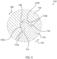
- a detailed view of engagement of the toothed hub 102 with the grooved rotor 104 is provided in accordance with an embodiment of the invention.
- a load present on the motor will cause the drive shaft 110 to rotate in the direction of the load to the extent allowed by the grooved rotor 104.
- the drive shaft 110 will rotate until one or more teeth 122 of the toothed hub 102 engage an interior surface of a groove 126 on the grooved rotor 104.
- the side wall 123 of each tooth 122 will be held against an interior edge 124 of one of the grooves 126.
- the load applied to the motor is represented by a vector force (128 or 132) having a direction and a magnitude, as applied by a load in the system 10 against the brake 60.
- a force in the direction of arrow 128 is being applied to the motor shaft 110 and forcing a first side wall 123a of each tooth 122 against a first interior surface 124a of the groove 126.
- each groove 126 is larger than the width of each tooth 122.
- a gap 130 exists between a second side wall 123b of each tooth 122 and an opposing, second interior surface 124b of the groove 126.
- the grooved rotor 104 is machined to closely engage the toothed hub 102, some space exists between each groove 126 and each tooth 122, defining the gap 130 and resulting in some backlash in the system.
- the gap 130 provides a limited amount of rotational movement of the motor 70 in a direction opposite the direction that the load is being applied.
- the gap 130 which provides this limited amount of movement, may allow for determining the direction that the brake is being pulled. This may be accomplished, for example, by activating the motor 70 when the brake 60 is still engaged, to apply a torque in the direction of the gap 130.
- the motor drive 40 may apply sufficient voltage and current to overcome the load present on the motor 70 and cause the hub 102 to rotate in the direction of the gap 130.
- the limited amount of movement may be detected by the encoder 80 and the motor drive 40 may identify the movement by monitoring the position feedback signal 95 from the encoder 80.
- the motor drive 40 may record the level of voltage and/or current required to cause the movement and, thereby identify a level of torque required to suspend the load present on the motor 70.
- the motor drive 40 may, in turn, generate the recoded levels of voltage and/or current prior to releasing the brake 60, which generates a motor vector force 132 substantially opposite to the load vector force 128, such that little or no movement is seen on the motor shaft 110 when the brake 60 is released.
- a state and timing diagram illustrating a sequence of activating the motor 70 to determine a magnitude and direction of a desired pretorque to apply to the motor 70 prior to opening the brake 60 is illustrated according to one embodiment of the invention.
- the motor 70 is activated with the brake 60 engaged to apply torques in opposing directions.
- the position feedback signal 95 is monitored for movement of the motor 70. Based on the position feedback signal 95, a desired level of pretorque required to hold a load present on the motor 70 is determined.
- the motor 70 is activated to apply a torque having a magnitude and in a direction determined to be opposite the direction of the load present on the motor 70 before releasing the brake 60, is provided.
- a run command 150 is initially provided to the motor drive 40 controlling operation of the motor 70.
- the run command 150 is maintained for a duration, identified as t run , in order to execute the pretorque routine. Although illustrated as returning, to zero, the run command may remain on for a duration after the pretorque duration, t run , to control operation of the motor 70 and move the elevator cab 14 between floor.
- a first state 160 (labeled "1" in Fig. 6D ), the brake 60 remains deenergized or set, thereby causing the brake to engage the motor shaft 110 and hold the motor in position. As indicated above, however, a certain amount of backlash exists in the holding brake.
- the motor drive 40 activates the motor 70 to ramp-up a first torque 152a applied to the drive shaft 110.
- Activataion of the motor 70 includes providing a variable voltage and/or a variable current at the output 22 of the motor drive to achieve a desired torque on the drive shaft 110.
- the drive shaft is splined to the toothed hub 1 02 and, thereby transfers the torque generated by the motor 70 to the hub 102 of the brake 60.
- the first torque 152a is illustrated as "ramping up" throughout the first state 160.
- the current output to the motor 70 is increased by the motor drive 40 in a manner that results in a linear increase of torque from zero torque at the start of the first state 1 60 to one hundred percent torque and the end of the first state 160.
- various other methods of increasing the torque such as periodic step changes or a sinusoidal increase of the torque may be utilized without deviating from the scope of the invention.
- the current is generated such that the torque, Trq, increases in a first direction throughout the desired range of magnitudes.
- the first direction may be, for example, a "positive" or clockwise direction of rotation of the motor shaft 110.
- the first torque 152a may or may not produce a motion detected by the encoder depending on the force 128 or 132 applied to the hub 102 by the load present on the motor 70.
- Motion is detected by the position feedback signal 95 which may be, for example, encoder counts representing a motion of the rotor or drive shaft 110 with respect to the brake 60.
- the amount of motion is limited by the width of the gap 130 between a surface of the tooth 122 and a surface of the groove 126. This motion is indicated by the step change in angular position, ⁇ , from zero to Delta, ⁇ , in Fig. 6c .
- a second state 162 (labeled “2" in Fig. 6D ) the brake 60 is still applied and the motor drive 40 decreases the first torque 152a applied to the motor 70.
- the first torque 152a is illustrated as "ramping down” throughout the second state 162.
- the current output to the motor 70 is decreased by the motor drive 40 in a manner that results in a linear decrease of torque from one hundred percent torque at the start of the second state 162 to zero torque and the end of the second state 162.
- various other methods of decreasing the torque such as periodic step changes or a sinusoidal decrease of the torque may be utilized without deviating from the scope of the invention.
- the first torque 152a is applied for a first duration 153a of the pretorque sequence.
- first torque 152a is illustrated as ramping up from zero torque to one hundred percent torque and then ramping back down to zero torque, it is contemplated that various other initial and final setpoints of torque may be selected without deviating from the scope of the invention.
- decreasing the magnitude of torque in the second state 162 may or may not produce a motion detected by the encoder 80 depending on the force 128 or 132 applied to the hub 102 by the load present on the motor 70. If motion was detected during the initial ramp in the first state 160, this indicates the torque applied was sufficient to overcome the load and that the force applied 128 or 132 was in the direction opposite of the torque applied. As a result, the torque applied during the first state caused the hub 102 to rotate such that the tooth 122 moved from one side of the groove 126 to the other. As the magnitude of torque is ramped back to zero, the force applied 128 or 132 by the load causes the hub 102 to rotate back to its initial position.
- This motion is detected by the position feedback signal 95 which may be, for example, encoder counts representing a motion of the rotor or drive shaft 110 with respect to the brake 60.
- the amount of motion is limited by the width of the gap 130 between a surface of the tooth 122 and a surface of the groove 126.
- This motion is indicated by the step change in angular position, ⁇ , from Delta, ⁇ , back to zero in Fig. 6c .
- a third state 164 (labeled "3" in Fig. 6D ) the brake 60 remains deenergized or set, thereby causing the brake to engage the motor shaft 110 and hold the motor in position. As indicated above, however, a certain amount of backlash exists in the holding brake.
- the motor drive 40 again activates the motor 70 to ramp-down a second torque 152b applied to the drive shaft 110.
- activation of the motor 70 includes providing a variable voltage and/or a variable current at the output 22 of the motor drive to achieve a desired torque on the drive shaft 110.
- the polarity, or direction, in which the torque is applied changes between the first torque 152a and the second torque 152b.
- FIG. 6B shows the first torque 152a being applied in a positive direction and the second torque 152b being applied in a negative direction.
- the second torque 152b is illustrated as "ramping down" throughout the third state 164, the magnitude of torque is increasing, but in a negative direction.
- the current output to the motor 70 is increased by the motor drive 40 in a manner that results in a linear increase of torque from zero torque at the start of the third state 164 to negative one hundred percent torque and the end of the third state 164, where the negative sign indicates a reversal of direction of the applied torque from the first state 160.
- various other methods of increasing the torque such as periodic step changes or a sinusoidal increase of the torque may be utilized without deviating from the scope of the invention.
- the current is generated such that the torque, Trq, increases in the second direction throughout the desired range of magnitudes.
- the second direction is opposite the first direction and may be, for example, a "negative" or counter-clockwise direction of rotation of the motor shaft 110.
- the second torque 152b may or may not produce a motion detected by the encoder depending on the force 128 or 132 applied to the hub 102 by the load present on the motor 70.
- Motion is detected by the position feedback signal 95 which may be, for example, encoder counts representing a motion of the rotor or drive shaft 110 with respect to the brake 60.
- the amount of motion is limited by the width of the gap 130 between a surface of the tooth 122 and a surface of the groove 126. This motion is indicated by the step change in angular position, ⁇ , from zero to negative Delta, - ⁇ , in Fig. 6c .
- a fourth state 166 (labeled "4" in Fig. 6D ) the brake 60 is still applied and the motor drive 40 decreases the magnitude of the second torque 152b applied to the motor 70.
- the second torque 152b is illustrated as "ramping up” throughout the fourth state 166.
- the magnitude of the torque is decreasing but it is a negative value of torque.
- the second torque 152b is changing from a maximum negative value to zero.
- the current output to the motor 70 is decreased by the motor drive 40 in a manner that results in a linear decrease of torque from negative one hundred percent torque at the start of the fourth state 166 to zero torque and the end of the fourth state 166.
- the second torque 152b is applied for a second duration 153b of the pretorque sequence. Although the second torque 152b is illustrated as ramping from zero torque to negative one hundred percent torque and then ramping back to zero torque, it is contemplated that various other initial and final setpoints of torque may be selected without deviating from the scope of the invention.
- decreasing the magnitude of torque in the fourth state 166 may or may not produce a motion detected by the encoder 80 depending on the force 128 or 132 applied to the hub 102 by the load present on the motor 70. If motion was detected during the initial ramp in the third state 164, this indicates the torque applied was sufficient to overcome the load and that the force applied 128 or 132 was in the direction opposite of the torque applied. As a result, the torque applied during the third state 164 caused the hub 102 to rotate such that the tooth 122 moved from one side of the groove 126 to the other. As the magnitude of torque is ramped back to zero, the force applied 128 or 132 by the load causes the hub 102 to rotate back to its initial position.
- This motion is detected by the position feedback signal 95 which may be, for example, encoder counts representing a motion of the rotor or drive shaft 110 with respect to the brake 60.
- the amount of motion is limited by the width of the gap 130 between a surface of the tooth 122 and a surface of the groove 126.
- This motion is indicated by the step change in angular position, ⁇ , from negative Delta, - ⁇ , back to zero in Fig. 6c .
- the feedback signal 95 from the encoder 80 may be monitored to detect motion in the system.
- the motion corresponds to an angular rotation of the drive shaft 110 in either direction as the torque is increased/decreased.
- the motor drive 40 may utilize the detected motion to determine both a direction and a magnitude of a desired pretorque level for the motor to apply prior to releasing the brake 60.
- the direction of the pretorque is determined as a function of the polarity of the torque that is applied to cause motion of the drive shaft 110 during states 1-4.
- Fig. 6 illustrates motion occurring in either direction and as a function both positive and negative torque
- Fig. 6c illustrates four different runs where each run is represented by a different line. Along each line, motion occurs responsive only to one of the directions of torque applied in Fig. 6B .
- force vector 128 is a positive direction
- application of additional torque in the positive direction i.e., states 1 and 2 result in pressing the first side wall 123a of the tooth 122 against the first interior surface 124a of the groove 126 with greater force.
- the brake 60 will resist further movement in that direction and, therefore, little or no movement is detected.
- application of torque in the negative direction i.e., states 3 and 4
- This rotation causes the angular position, ⁇ , in Fig. 6c to move from zero to negative Delta, - ⁇ .
- the magnitude of the pretorque is determined as a function of the magnitude of torque required to cause motion of the drive shaft 110 during states 1-4.
- the magnitude of pretorque required to hold the load corresponds to the magnitude of torque being applied when the angular position, ⁇ , changes or in other words the magnitude of pretorque required to hold the load corresponds to the magnitude of torque required to cause the hub 102 to move within the grooved rotor plate 104 of the holding brake 60.
- the identified level of pretorque is applied in state 6, 170.
- the levels shown in state 6 170 of Fig. 6B correspond to the level of torque being applied when movement of the hub 102 is detected by the position feedback signal 95.
- a first plot in Fig. 6c has a wide band at which the angular position, ⁇ , is at Delta, ⁇ . Tracing the change in angular position, ⁇ , shown in Fig. 6c up to the corresponding level of torque, Trq, illustrated in Fig. 6b , the level of torque required to cause the change in position is relatively low. When the level of torque again drops below the initial level required to cause the first change in angular position, ⁇ , the second change in angular position shows the angular position returning from Delta, ⁇ , to zero.
- the second plot in Fig. 6c has a narrower band at which the angular position, ⁇ , is at Delta, ⁇ , than the first plot. Tracing the change in angular position, ⁇ , shown in Fig. 6c up to the corresponding level of torque, Trq, illustrated in Fig. 6b , the level of torque required to cause the change in position is greater than that required to cause the change for the first plot. When the level of torque again drops below the level required to cause the first change in angular position, ⁇ , the second change in angular position shows the angular position returning from Delta, ⁇ , to zero.
- the motor drive 40 may ramp up the current and, therefore, the first torque 152a produced by the motor 70 in the first direction from an initial magnitude of about 0% of rated torque on the motor 70 to a final magnitude of about 100% of rated torque.
- the encoder 80 may initially detect motion at a magnitude of about 20% of rated torque on the motor 70 for the first plot discussed above and at a magnitude of about 80% of rated toque for the second plot discussed above.
- the motor drive 40 may determine the correct pretorque magnitude (20% or 80%) and direction (first direction) for the pre-torque to hold the mechanical load being applied to the motor 70.
- the motor drive 40 may ramp up the magnitude of current in the second direction, or in an opposite polarity from the first direction, and, therefore, the second torque 152b is produced by the motor 70 in the second direction.
- the second torque 152b is illustrated as ramping down to a negative torque, meaning the magnitude of torque changes from an initial magnitude of about 0% of rated torque on the motor 70 to a final magnitude of about 100% of rated torque, but the direction of the second torque 152b is applied opposite the direction of the first torque 152a.
- the encoder 80 may initially detect motion at a magnitude of about -20% of rated torque on the motor 70 for the third plot shown in Fig.
- the motor drive 40 may determine the correct pretorque magnitude (20% or 80%) and direction (second direction) for the pre-torque to hold the mechanical load being applied to the motor 70.
- the motor drive After determining the direction and magnitude of a pretorque required to suspend the mechanical load being applied to the motor 70, the motor drive applies that torque in state 5 168. As shown, in Fig. 6b , the torque is ramped from zero torque to the magnitude and direction of the required pretorque identified in the first four states. When the pretorque reaches the required level, the angular position may again move such that hub 102 rotates within the grooved rotor 104.
- the pretorque level may be selected at a level just prior to motion occurring such that no motion occurs when the pretorque is applied, but also the motor 70 is very nearly at the level of torque required to suspend the load prior to opening the brake 60.
- the brake is energized, causing the armature plate 114 to disengage the friction pads 105 on the rotor disk 104, allowing the hub 102 to rotate.
- the motor 70 By first activating the motor 70 to apply a level of torque in the proper to support the mechanical load applied to the motor 70, a smooth transition from the brake 60 supporting the load to the motor 70 supporting the load occurs.
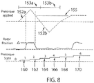
- FIG. 8 a state and timing diagram illustrating activation and resulting motion of the motor 70 during an exemplary start of the motor is provided in accordance with an embodiment of the invention.
- an initial pretorque state (labeled "0") is shown.
- the amount of torque 180 applied by the motor 70 is zero, and the position sensor 80 or encoder detects approximately zero motion with respect to a rotor or drive shaft.
- the motor drive ramps-up the amount of torque 152a applied by the motor in a first direction through multiple increasing magnitudes.
- the position sensor 80 or encoder detects motion.
- the angular position indicates that the rotor has moved the relative maximum amount, or Delta, ⁇ , as discussed above, thereby indicating that any greater amount of torque is unnecessary to provide the movement through the gap 130 in the brake 60.
- the motor drive 40 enters the second pre-torque state 162 (labeled "2").
- the motor drive 40 gradually ramps-down the first torque 152a applied by the motor through multiple decreasing magnitudes.
- the position sensor or encoder may again capture an amount of motion, indicating the rotor or drive shaft returning to again to its original brake position.
- the motor drive may later use this data from the encoder from the first state, the second state, or both states (such as to determine an average) for determining a correct pre-torque magnitude for subsequent application.
- the motor drive 40 enters a third pre-torque state 164 (labeled "3").
- the motor drive gradually ramps-up an amount of torque 152b applied by the motor in a second direction, opposite the first direction, through multiple increasing magnitudes.
- the amount of torque applied by the motor reaches 100%, the position sensor or encoder has detected approximately zero motion with respect to a rotor or drive shaft,
- the motor drive 40 moves to the fourth pre-torque state 1 66 (labeled "4") and gradually ramps-down the amount of torque 152b applied by the motor through multiple decreasing magnitudes. Through the ramp-down of the second torque 152b, the position sensor or encoder captures approximately zero motion.
- the controller may now determine that a pretorque magnitude of 60% in the first direction will be sufficient to lift the load from the brake.
- the motor drive 40 With the brake still applied, the motor drive 40 enters a fifth pre-torque state 168 (labeled "5"). The motor drive 40 gradually ramps-up the amount of torque applied by the motor to the correct pre-torque 155 of 60% in the first direction. As the amount of torque applied by the motor gradually reaches approximately 60%, the position sensor or encoder may capture an increasing amount of motion, which motion may again reach a relative maximum.
- the motor drive 40 Upon applying the pre-torque, the motor drive 40 enters a sixth pre-torque state 170 (labeled "6") and disengages/releases the brake 60.
- the motor drive 40 may typically run through the above six states in less than a second. Having now provided a smooth transition from brake to drive with the brake fully disengaged and the motor fully engaged, following the sixth state, the controller may continue with normal operation to carry the load, such as an elevator cab, to a desired position,
Landscapes
- Engineering & Computer Science (AREA)
- Automation & Control Theory (AREA)
- Power Engineering (AREA)
- Control Of Electric Motors In General (AREA)
- Connection Of Motors, Electrical Generators, Mechanical Devices, And The Like (AREA)
- Elevator Control (AREA)
- Braking Arrangements (AREA)
Claims (13)
- Verfahren zum Bestimmen eines gewünschten Vordrehmomentpegels für einen Motor, der die Bewegung in einem Gewichtsausgleichssystem steuert, wobei der Motor eine Haltebremse aufweist, die mit einer Antriebswelle des Motors operativ verbunden ist, wobei das Verfahren die folgenden Schritte beinhaltet:Erhöhen einer Stärke von dem Motor (70) zugeführtem Strom, um ein Drehmoment in einer ersten Drehrichtung zu erzeugen, während die Haltebremse (60) angelegt ist;Überwachen eines Positionsrückmeldesignals (95) entsprechend der Drehung des Motors, während das Drehmoment in der ersten Richtung erzeugt wird;Wegnehmen des dem Motor zugeführten Stroms, um ein Drehmoment in der ersten Drehrichtung zu erzeugen;Erhöhen der Stärke des dem Motor zugeführten Stroms, um ein Drehmoment in einer zweiten Drehrichtung zu erzeugen, während die Haltebremse angelegt ist;Überwachen des Positionsrückmeldesignals entsprechend der Drehung des Motors, während das Drehmoment in der zweiten Richtung erzeugt wird;Entfernen des dem Motor zugeführten Stroms, um ein Drehmoment in der zweiten Drehrichtung zu erzeugen; undBestimmen des gewünschten Vordrehmomentpegels als eine Funktion der Stärke von dem Motor zugeführtem Strom und einer Größe der durch das Positionsrückmeldesignal erfassten Drehung.
- Verfahren nach Anspruch 1, wobei der Schritt des Bestimmens des gewünschten Vordrehmomentpegels ferner die folgenden Schritte beinhaltet:Vergleichen einer Änderung des Positionsrückmeldesignals mit einem ersten Schwellenwert; undEinstellen des gewünschten Vordrehmomentpegels auf die Stärke des dem Motor zugeführten Stroms, wenn die Änderung des Positionsrückmeldesignals den ersten Schwellenwert erreicht.
- Verfahren nach Anspruch 1, wobei der Schritt des Bestimmens des gewünschten Vordrehmomentpegels ferner die folgenden Schritte beinhaltet:Vergleichen einer Änderung des Positionsrückmeldesignals mit einem ersten Schwellenwert;Überwachen, wenn die Änderung des Positionsrückmeldesignals den ersten Schwellenwert überschreitet, des Positionsrückmeldesignals, bis die Änderung des Positionsrückmeldesignals wieder unter den ersten Schwellenwert fällt; undEinstellen, wenn die Änderung des Positionsrückmeldesignals wieder unter den ersten Schwellenwert fällt, des gewünschten Vordrehmomentpegels auf die Stärke des dem Motor zugeführten Stroms, wenn die Änderung des Positionsrückmeldesignals wieder unter den ersten Schwellenwert fällt.
- Verfahren nach einem der Ansprüche 1 bis 3, das ferner den Schritt des Applizierens einer Stromstärke auf den Motor beinhaltet, um vor dem Lösen der Haltebremse ein Drehmoment auf dem gewünschten Vordrehmomentpegel zu erzeugen.
- Verfahren nach einem der Ansprüche 1 bis 3, wobei der Schritt des Erhöhens der Stärke des dem Motor zugeführten Stroms, um ein Drehmoment in der ersten Drehrichtung zu erzeugen, ein inkrementelles Ändern der Stärke des dem Motor zugeführten Stroms von einem ersten Pegel auf einen zweiten Pegel beinhaltet.
- Verfahren nach einem der Ansprüche 1 bis 3, wobei der Schritt des Erhöhens der Stärke des dem Motor zugeführten Stroms, um ein Drehmoment in der zweiten Drehrichtung zu erzeugen, ein inkrementelles Ändern der Stärke des dem Motor zugeführten Stroms von einem dritten Pegel auf einen vierten Pegel beinhaltet.
- System zum Bestimmen eines gewünschten Vordrehmomentpegels für einen Motor, der die Bewegung in einem Gewichtsausgleichssystem steuert, wobei der Motor eine Haltebremse aufweist, die mit einer Antriebswelle des Motors operativ verbunden ist, wobei das System Folgendes umfasst:einen Stromrichter, der mit dem Motor (70) operativ verbunden ist, um dem Motor eine variable Spannung und einen variablen Strom zum Steuern des Betriebs des Motors zuzuführen;ein Positionsrückmeldegerät (80), das mit dem Motor operativ verbunden und zum Erzeugen eines Signals (95) entsprechend einer Winkelposition des Motors konfiguriert ist; undeine Steuerung, die Folgendes aufweist:einen Eingang mit der Aufgabe, das Signal von dem Positionsrückmeldegerät zu empfangen;ein Speichergerät (52) mit der Aufgabe, mehrere Befehle zu speichern; undeinen Prozessor (50) mit der Aufgabe, die mehreren Befehle auszuführen zum:Steuern des Betriebs des Stromrichters zum Zuführen von Strom einer zunehmenden Stärke mit einer ersten Polarität zum Motor, während die Haltebremse angelegt ist, wobei der Strom von einem ersten Pegel auf einen zweiten Pegel zunimmt und ein Drehmoment im Motor in einer ersten Drehrichtung erzeugt,Überwachen des Signals vom Positionsrückmeldegerät, während dem Motor Strom von zunehmender Stärke mit der ersten Polarität zugeführt wird,Steuern des Betriebs des Stromrichters, um dem Motor Strom von abnehmender Stärke mit der ersten Polarität zuzuführen, während die Haltebremse angelegt ist, wobei der Strom vom zweiten Pegel auf den ersten Pegel abnimmt,Steuern des Betriebs des Stromrichters, um dem Motor Strom von zunehmender Stärke mit einer zweiten Polarität zuzuführen, während die Haltebremse angelegt ist, wobei der Strom vom ersten Pegel auf einen dritten Pegel zunimmt, die zweite Polarität der ersten Polarität entgegengesetzt ist und der Strom ein Drehmoment im Motor in einer zweiten Drehrichtung erzeugt,Überwachen des Signals vom Positionsrückmeldegerät, während dem Motor Strom von zunehmender Stärke mit der zweiten Polarität zugeführt wird,Steuern des Betriebs des Stromrichters, um dem Motor Strom von abnehmender Stärke mit der zweiten Polarität zuzuführen, während die Haltebremse angelegt ist, wobei der Strom vom dritten Pegel auf den ersten Pegel abnimmt, undBestimmen des gewünschten Vordrehmomentpegels als eine Funktion der Stärke des dem Motor zugeführten Stroms und einer Größe der durch das Positionsrückmeldesignal erfassten Drehung.
- System nach Anspruch 7, das ferner einen Motorantrieb (40) umfasst, wobei der Stromrichter ein Stromwandlungsteil (43) des Motorantriebs ist und die Steuerung ein Steuerteil (45) des Motorantriebs ist.
- System nach Anspruch 7 oder 8, wobei der gewünschte Vordrehmomentpegel als Funktion der Stärke des dem Motor zugeführten Stroms bestimmt wird, während die Stromstärke zunimmt.
- System nach Anspruch 9, wobei der Prozessor ferner die folgenden Aufgaben hat:Vergleichen einer Änderung des Signals vom Positionsrückmeldegerät mit einem ersten Schwellenwert, undEinstellen des gewünschten Vordrehmomentpegels auf die Stärke des dem Motor zugeführten Stroms, wenn die Änderung des Signals vom Positionsrückmeldegerät den ersten Schwellenwert erreicht.
- System nach Anspruch 7 oder 8, wobei der gewünschte Vordrehmomentpegel als eine Funktion der Stärke des dem Motor zugeführten Stroms bestimmt wird, wenn die Stromstärke abnimmt.
- System nach Anspruch 11, wobei der Prozessor ferner die folgenden Aufgaben hat:Vergleichen einer Änderung des Signals vom Positionsrückmeldegerät mit einem ersten Schwellenwert,Überwachen, wenn die Änderung des Signals vom Positionsrückmeldegerät den ersten Schwellenwert überschreitet, des Signals vom Positionsrückmeldegerät, bis die Änderung des Signals wieder unter den ersten Schwellenwert fällt, undEinstellen, wenn die Änderung des Signals vom Positionsrückmeldegerät wieder unter den ersten Schwellenwert fällt, des gewünschten Vordrehmomentpegels auf die Stärke des dem Motor zugeführten Stroms, wenn die Änderung des Signals vom Positionsrückmeldegerät wieder unter den ersten Schwellenwert fällt.
- System nach Anspruch 7, wobei der Prozessor ferner die Aufgabe hat, den Betrieb des Stromrichters zu steuern, um dem Motor Strom einer Stärke zuzuführen, um ein Drehmoment auf dem gewünschten Vordrehmomentpegel zu erzeugen, bevor die Haltebremse gelöst wird.
Applications Claiming Priority (2)
| Application Number | Priority Date | Filing Date | Title |
|---|---|---|---|
| US201662288776P | 2016-01-29 | 2016-01-29 | |
| PCT/US2017/015365 WO2017132525A1 (en) | 2016-01-29 | 2017-01-27 | Method and apparatus for controlling motion in a counterbalancing system |
Publications (3)
| Publication Number | Publication Date |
|---|---|
| EP3408204A1 EP3408204A1 (de) | 2018-12-05 |
| EP3408204A4 EP3408204A4 (de) | 2019-09-25 |
| EP3408204B1 true EP3408204B1 (de) | 2021-07-14 |
Family
ID=59387675
Family Applications (1)
| Application Number | Title | Priority Date | Filing Date |
|---|---|---|---|
| EP17744983.2A Active EP3408204B1 (de) | 2016-01-29 | 2017-01-27 | Verfahren und vorrichtung zur steuerung der bewegung in einem gewichtsausgleichssystem |
Country Status (9)
| Country | Link |
|---|---|
| US (1) | US9973114B2 (de) |
| EP (1) | EP3408204B1 (de) |
| JP (1) | JP6525226B2 (de) |
| CN (1) | CN108883890B (de) |
| AU (1) | AU2017212650B2 (de) |
| CA (1) | CA3013036C (de) |
| ES (1) | ES2884359T3 (de) |
| SG (1) | SG11201806441PA (de) |
| WO (1) | WO2017132525A1 (de) |
Families Citing this family (13)
| Publication number | Priority date | Publication date | Assignee | Title |
|---|---|---|---|---|
| US10044156B1 (en) | 2017-04-26 | 2018-08-07 | EMC IP Holding Company, LLC | Cable management |
| US10154607B1 (en) | 2017-04-26 | 2018-12-11 | EMC IP Holding Company LLC | Cable management |
| US10154608B1 (en) * | 2017-04-26 | 2018-12-11 | EMC IP Holding Company LLC | Cable management |
| GB2566497B (en) | 2017-09-15 | 2020-07-29 | Illinois Tool Works | Braking system for electromagnetic motors |
| GB2585471B (en) * | 2017-09-15 | 2021-07-21 | Illinois Tool Works | Braking system for electromagnetic motors |
| US10663365B2 (en) * | 2017-09-27 | 2020-05-26 | Rockwell Automation Technologies, Inc. | Method for measuring motor brake health |
| EP3556699A1 (de) * | 2018-04-19 | 2019-10-23 | KONE Corporation | Überwachungslösung für ein fördersystem |
| US10483740B1 (en) * | 2018-10-12 | 2019-11-19 | Kone Corporation | Floor board junction box |
| EP3885300B1 (de) * | 2020-03-27 | 2024-05-01 | KONE Corporation | Verfahren zur identifizierung von magnetisierungachsen- und drehmomentachseinduktivitäten eines permanentmagnetmotors eines aufzugs, und aufzugsantriebseinheit |
| US11815885B2 (en) * | 2021-02-10 | 2023-11-14 | Rockwell Automation Technologies, Inc. | System and method for safe retention of loads with stored potential energy |
| CN114710071A (zh) * | 2022-05-05 | 2022-07-05 | 浙江湖州森富机电有限责任公司 | 一种门体用无刷直流管状电机的控制方法 |
| CN116281464B (zh) * | 2023-05-24 | 2023-07-25 | 广东轩宇机械科技有限公司 | 双柱施工升降机及升降机控制方法 |
| CN116675047A (zh) * | 2023-06-27 | 2023-09-01 | 合肥神马科技集团有限公司 | 一种骨架层锁扣机动载平衡的控制系统及方法 |
Citations (1)
| Publication number | Priority date | Publication date | Assignee | Title |
|---|---|---|---|---|
| US5025896A (en) * | 1988-03-18 | 1991-06-25 | Hitachi, Ltd. | Elevator control apparatus |
Family Cites Families (17)
| Publication number | Priority date | Publication date | Assignee | Title |
|---|---|---|---|---|
| US5077508A (en) | 1989-01-30 | 1991-12-31 | Wycoff David C | Method and apparatus for determining load holding torque |
| US5076399A (en) | 1990-09-28 | 1991-12-31 | Otis Elevator Company | Elevator start control technique for reduced start jerk and acceleration overshoot |
| US5424498A (en) | 1993-03-31 | 1995-06-13 | Otis Elevator Company | Elevator start jerk removal |
| JPH07228438A (ja) * | 1994-02-15 | 1995-08-29 | Hitachi Ltd | マルチインバータ式エレベータの制御装置及びその方法 |
| FI97797C (fi) | 1994-09-30 | 1997-02-25 | Kone Oy | Menetelmä hissin käynnistämiseksi |
| EP0807084B1 (de) | 1995-01-31 | 2004-08-25 | Kone Corporation | Steuerungsverfahren und -vorrichtung für aufzughebemotor |
| FI981887A7 (fi) | 1998-09-04 | 2000-03-05 | Kone Corp | Hissijärjestely hissikoneiston moottorin lähtömomentin asettamiseksi |
| US6488128B1 (en) | 2000-12-12 | 2002-12-03 | Otis Elevator Company | Integrated shaft sensor for load measurement and torque control in elevators and escalators |
| US6566830B2 (en) | 2001-08-17 | 2003-05-20 | Delphi Technologies, Inc. | Method and system for controlling a permanent magnet machine |
| WO2006119787A1 (en) * | 2005-05-09 | 2006-11-16 | Otis Elevator Company | Method for controlling an elevator drive device and related operartion device for an elevator system |
| JP2006335553A (ja) * | 2005-06-06 | 2006-12-14 | Yaskawa Electric Corp | エレベータ制御装置とその制御方法 |
| US7902689B2 (en) | 2009-07-07 | 2011-03-08 | General Electric Company | Method and system for noise controlled operation of a wind turbine |
| JP5446627B2 (ja) * | 2009-09-08 | 2014-03-19 | 株式会社安川電機 | エレベータの制御装置及びその制御方法 |
| FI20090335L (fi) | 2009-09-16 | 2011-03-17 | Kone Corp | Menetelmä ja järjestely hissikorin hallitsemattoman liikkeen estämiseksi |
| JP5672053B2 (ja) * | 2011-02-22 | 2015-02-18 | 東芝三菱電機産業システム株式会社 | モーター停止用の制御装置 |
| KR20130057902A (ko) | 2011-11-24 | 2013-06-03 | 엘에스산전 주식회사 | 엘리베이터의 제어 방법, 엘리베이터 제어 장치 및 이를 이용한 엘리베이터 장치 |
| US9093937B2 (en) * | 2013-07-12 | 2015-07-28 | Magnetek, Inc. | Method and apparatus for determining position for a permanent magnet elevator motor |
-
2017
- 2017-01-27 ES ES17744983T patent/ES2884359T3/es active Active
- 2017-01-27 CN CN201780021516.6A patent/CN108883890B/zh not_active Expired - Fee Related
- 2017-01-27 AU AU2017212650A patent/AU2017212650B2/en active Active
- 2017-01-27 WO PCT/US2017/015365 patent/WO2017132525A1/en not_active Ceased
- 2017-01-27 US US15/418,118 patent/US9973114B2/en active Active
- 2017-01-27 CA CA3013036A patent/CA3013036C/en active Active
- 2017-01-27 JP JP2018539887A patent/JP6525226B2/ja active Active
- 2017-01-27 EP EP17744983.2A patent/EP3408204B1/de active Active
- 2017-01-27 SG SG11201806441PA patent/SG11201806441PA/en unknown
Patent Citations (1)
| Publication number | Priority date | Publication date | Assignee | Title |
|---|---|---|---|---|
| US5025896A (en) * | 1988-03-18 | 1991-06-25 | Hitachi, Ltd. | Elevator control apparatus |
Also Published As
| Publication number | Publication date |
|---|---|
| CN108883890A (zh) | 2018-11-23 |
| EP3408204A4 (de) | 2019-09-25 |
| JP2019503321A (ja) | 2019-02-07 |
| JP6525226B2 (ja) | 2019-06-05 |
| CN108883890B (zh) | 2020-07-28 |
| SG11201806441PA (en) | 2018-08-30 |
| HK1257674A1 (zh) | 2019-10-25 |
| AU2017212650A1 (en) | 2018-09-13 |
| US20170222577A1 (en) | 2017-08-03 |
| WO2017132525A1 (en) | 2017-08-03 |
| ES2884359T3 (es) | 2021-12-10 |
| AU2017212650B2 (en) | 2019-04-11 |
| US9973114B2 (en) | 2018-05-15 |
| CA3013036C (en) | 2023-01-03 |
| EP3408204A1 (de) | 2018-12-05 |
| CA3013036A1 (en) | 2017-08-03 |
Similar Documents
| Publication | Publication Date | Title |
|---|---|---|
| EP3408204B1 (de) | Verfahren und vorrichtung zur steuerung der bewegung in einem gewichtsausgleichssystem | |
| EP2923986B1 (de) | Verfahren und Vorrichtung zur Konfiguration eines automatischen Aufzugsantriebs | |
| US12258241B2 (en) | Elevator including safety monitoring that prevents excessive deceleration during slowdown failure | |
| EP2694416B1 (de) | Verfahren zur betriebszustandsüberwachung einer aufzugsanlage und aufzugsanlage | |
| CN101468769B (zh) | 电梯的开门行驶防止系统 | |
| JP3803128B2 (ja) | 電気駆動装置の監視及び/又は回転数の制御方法及び装置 | |
| EP2824825B1 (de) | Verfahren und Vorrichtung zur Bestimmung der Position für einen Permanentmagnetmotor für Aufzüge | |
| US11554933B2 (en) | Elevator | |
| EP2547616B1 (de) | Verfahren und vorrichtung zum starten des elektrischen antriebs eines fahrzeugs | |
| JP2014240817A (ja) | エンコーダ異常検出装置及びエンコーダ異常検出装置を用いたエレベータ装置 | |
| EP4341190B1 (de) | System und verfahren zur erkennung einer schleppbremse in einer aufzugsanwendung | |
| JP5476681B2 (ja) | 昇降システムのモータ制御装置 | |
| JP2009525239A (ja) | エレベータ駆動システム内のエンコーダの不具合の管理 | |
| HK1257674B (en) | Method and apparatus for controlling motion in a counterbalancing system | |
| EP3753891A1 (de) | Notbremsgeräte | |
| KR101913592B1 (ko) | 엘리베이터의 안티롤백 기동방법 | |
| CN105143079B (zh) | 电梯的控制装置 | |
| EP4370462B1 (de) | Sicherheitslösung für aufzüge | |
| HK40098717A (zh) | 用於电梯的安全方案 | |
| HK1206153B (en) | Method and apparatus for determining position for a permanent magnet elevator motor | |
| JPH0732815U (ja) | 昇降装置 |
Legal Events
| Date | Code | Title | Description |
|---|---|---|---|
| STAA | Information on the status of an ep patent application or granted ep patent |
Free format text: STATUS: THE INTERNATIONAL PUBLICATION HAS BEEN MADE |
|
| PUAI | Public reference made under article 153(3) epc to a published international application that has entered the european phase |
Free format text: ORIGINAL CODE: 0009012 |
|
| STAA | Information on the status of an ep patent application or granted ep patent |
Free format text: STATUS: REQUEST FOR EXAMINATION WAS MADE |
|
| 17P | Request for examination filed |
Effective date: 20180730 |
|
| AK | Designated contracting states |
Kind code of ref document: A1 Designated state(s): AL AT BE BG CH CY CZ DE DK EE ES FI FR GB GR HR HU IE IS IT LI LT LU LV MC MK MT NL NO PL PT RO RS SE SI SK SM TR |
|
| AX | Request for extension of the european patent |
Extension state: BA ME |
|
| DAV | Request for validation of the european patent (deleted) | ||
| DAX | Request for extension of the european patent (deleted) | ||
| A4 | Supplementary search report drawn up and despatched |
Effective date: 20190823 |
|
| RIC1 | Information provided on ipc code assigned before grant |
Ipc: B66B 1/34 20060101ALI20190819BHEP Ipc: H02P 23/06 20160101ALI20190819BHEP Ipc: B66B 1/32 20060101ALI20190819BHEP Ipc: B66B 1/30 20060101AFI20190819BHEP |
|
| STAA | Information on the status of an ep patent application or granted ep patent |
Free format text: STATUS: EXAMINATION IS IN PROGRESS |
|
| 17Q | First examination report despatched |
Effective date: 20200709 |
|
| GRAP | Despatch of communication of intention to grant a patent |
Free format text: ORIGINAL CODE: EPIDOSNIGR1 |
|
| STAA | Information on the status of an ep patent application or granted ep patent |
Free format text: STATUS: GRANT OF PATENT IS INTENDED |
|
| INTG | Intention to grant announced |
Effective date: 20210218 |
|
| GRAS | Grant fee paid |
Free format text: ORIGINAL CODE: EPIDOSNIGR3 |
|
| GRAA | (expected) grant |
Free format text: ORIGINAL CODE: 0009210 |
|
| STAA | Information on the status of an ep patent application or granted ep patent |
Free format text: STATUS: THE PATENT HAS BEEN GRANTED |
|
| AK | Designated contracting states |
Kind code of ref document: B1 Designated state(s): AL AT BE BG CH CY CZ DE DK EE ES FI FR GB GR HR HU IE IS IT LI LT LU LV MC MK MT NL NO PL PT RO RS SE SI SK SM TR |
|
| REG | Reference to a national code |
Ref country code: GB Ref legal event code: FG4D |
|
| REG | Reference to a national code |
Ref country code: IE Ref legal event code: FG4D |
|
| REG | Reference to a national code |
Ref country code: DE Ref legal event code: R096 Ref document number: 602017042125 Country of ref document: DE |
|
| REG | Reference to a national code |
Ref country code: NL Ref legal event code: FP |
|
| REG | Reference to a national code |
Ref country code: AT Ref legal event code: REF Ref document number: 1410496 Country of ref document: AT Kind code of ref document: T Effective date: 20210815 |
|
| REG | Reference to a national code |
Ref country code: LT Ref legal event code: MG9D |
|
| REG | Reference to a national code |
Ref country code: ES Ref legal event code: FG2A Ref document number: 2884359 Country of ref document: ES Kind code of ref document: T3 Effective date: 20211210 |
|
| REG | Reference to a national code |
Ref country code: AT Ref legal event code: MK05 Ref document number: 1410496 Country of ref document: AT Kind code of ref document: T Effective date: 20210714 |
|
| PG25 | Lapsed in a contracting state [announced via postgrant information from national office to epo] |
Ref country code: RS Free format text: LAPSE BECAUSE OF FAILURE TO SUBMIT A TRANSLATION OF THE DESCRIPTION OR TO PAY THE FEE WITHIN THE PRESCRIBED TIME-LIMIT Effective date: 20210714 Ref country code: SE Free format text: LAPSE BECAUSE OF FAILURE TO SUBMIT A TRANSLATION OF THE DESCRIPTION OR TO PAY THE FEE WITHIN THE PRESCRIBED TIME-LIMIT Effective date: 20210714 Ref country code: HR Free format text: LAPSE BECAUSE OF FAILURE TO SUBMIT A TRANSLATION OF THE DESCRIPTION OR TO PAY THE FEE WITHIN THE PRESCRIBED TIME-LIMIT Effective date: 20210714 Ref country code: NO Free format text: LAPSE BECAUSE OF FAILURE TO SUBMIT A TRANSLATION OF THE DESCRIPTION OR TO PAY THE FEE WITHIN THE PRESCRIBED TIME-LIMIT Effective date: 20211014 Ref country code: PT Free format text: LAPSE BECAUSE OF FAILURE TO SUBMIT A TRANSLATION OF THE DESCRIPTION OR TO PAY THE FEE WITHIN THE PRESCRIBED TIME-LIMIT Effective date: 20211115 Ref country code: FI Free format text: LAPSE BECAUSE OF FAILURE TO SUBMIT A TRANSLATION OF THE DESCRIPTION OR TO PAY THE FEE WITHIN THE PRESCRIBED TIME-LIMIT Effective date: 20210714 Ref country code: BG Free format text: LAPSE BECAUSE OF FAILURE TO SUBMIT A TRANSLATION OF THE DESCRIPTION OR TO PAY THE FEE WITHIN THE PRESCRIBED TIME-LIMIT Effective date: 20211014 Ref country code: AT Free format text: LAPSE BECAUSE OF FAILURE TO SUBMIT A TRANSLATION OF THE DESCRIPTION OR TO PAY THE FEE WITHIN THE PRESCRIBED TIME-LIMIT Effective date: 20210714 Ref country code: LT Free format text: LAPSE BECAUSE OF FAILURE TO SUBMIT A TRANSLATION OF THE DESCRIPTION OR TO PAY THE FEE WITHIN THE PRESCRIBED TIME-LIMIT Effective date: 20210714 |
|
| PG25 | Lapsed in a contracting state [announced via postgrant information from national office to epo] |
Ref country code: PL Free format text: LAPSE BECAUSE OF FAILURE TO SUBMIT A TRANSLATION OF THE DESCRIPTION OR TO PAY THE FEE WITHIN THE PRESCRIBED TIME-LIMIT Effective date: 20210714 Ref country code: LV Free format text: LAPSE BECAUSE OF FAILURE TO SUBMIT A TRANSLATION OF THE DESCRIPTION OR TO PAY THE FEE WITHIN THE PRESCRIBED TIME-LIMIT Effective date: 20210714 Ref country code: GR Free format text: LAPSE BECAUSE OF FAILURE TO SUBMIT A TRANSLATION OF THE DESCRIPTION OR TO PAY THE FEE WITHIN THE PRESCRIBED TIME-LIMIT Effective date: 20211015 |
|
| REG | Reference to a national code |
Ref country code: DE Ref legal event code: R097 Ref document number: 602017042125 Country of ref document: DE |
|
| PG25 | Lapsed in a contracting state [announced via postgrant information from national office to epo] |
Ref country code: DK Free format text: LAPSE BECAUSE OF FAILURE TO SUBMIT A TRANSLATION OF THE DESCRIPTION OR TO PAY THE FEE WITHIN THE PRESCRIBED TIME-LIMIT Effective date: 20210714 |
|
| PLBE | No opposition filed within time limit |
Free format text: ORIGINAL CODE: 0009261 |
|
| STAA | Information on the status of an ep patent application or granted ep patent |
Free format text: STATUS: NO OPPOSITION FILED WITHIN TIME LIMIT |
|
| PG25 | Lapsed in a contracting state [announced via postgrant information from national office to epo] |
Ref country code: SM Free format text: LAPSE BECAUSE OF FAILURE TO SUBMIT A TRANSLATION OF THE DESCRIPTION OR TO PAY THE FEE WITHIN THE PRESCRIBED TIME-LIMIT Effective date: 20210714 Ref country code: SK Free format text: LAPSE BECAUSE OF FAILURE TO SUBMIT A TRANSLATION OF THE DESCRIPTION OR TO PAY THE FEE WITHIN THE PRESCRIBED TIME-LIMIT Effective date: 20210714 Ref country code: RO Free format text: LAPSE BECAUSE OF FAILURE TO SUBMIT A TRANSLATION OF THE DESCRIPTION OR TO PAY THE FEE WITHIN THE PRESCRIBED TIME-LIMIT Effective date: 20210714 Ref country code: EE Free format text: LAPSE BECAUSE OF FAILURE TO SUBMIT A TRANSLATION OF THE DESCRIPTION OR TO PAY THE FEE WITHIN THE PRESCRIBED TIME-LIMIT Effective date: 20210714 Ref country code: CZ Free format text: LAPSE BECAUSE OF FAILURE TO SUBMIT A TRANSLATION OF THE DESCRIPTION OR TO PAY THE FEE WITHIN THE PRESCRIBED TIME-LIMIT Effective date: 20210714 Ref country code: AL Free format text: LAPSE BECAUSE OF FAILURE TO SUBMIT A TRANSLATION OF THE DESCRIPTION OR TO PAY THE FEE WITHIN THE PRESCRIBED TIME-LIMIT Effective date: 20210714 |
|
| 26N | No opposition filed |
Effective date: 20220419 |
|
| PG25 | Lapsed in a contracting state [announced via postgrant information from national office to epo] |
Ref country code: MC Free format text: LAPSE BECAUSE OF FAILURE TO SUBMIT A TRANSLATION OF THE DESCRIPTION OR TO PAY THE FEE WITHIN THE PRESCRIBED TIME-LIMIT Effective date: 20210714 |
|
| REG | Reference to a national code |
Ref country code: BE Ref legal event code: MM Effective date: 20220131 |
|
| PG25 | Lapsed in a contracting state [announced via postgrant information from national office to epo] |
Ref country code: LU Free format text: LAPSE BECAUSE OF NON-PAYMENT OF DUE FEES Effective date: 20220127 |
|
| PG25 | Lapsed in a contracting state [announced via postgrant information from national office to epo] |
Ref country code: BE Free format text: LAPSE BECAUSE OF NON-PAYMENT OF DUE FEES Effective date: 20220131 |
|
| PG25 | Lapsed in a contracting state [announced via postgrant information from national office to epo] |
Ref country code: IE Free format text: LAPSE BECAUSE OF NON-PAYMENT OF DUE FEES Effective date: 20220127 |
|
| PG25 | Lapsed in a contracting state [announced via postgrant information from national office to epo] |
Ref country code: HU Free format text: LAPSE BECAUSE OF FAILURE TO SUBMIT A TRANSLATION OF THE DESCRIPTION OR TO PAY THE FEE WITHIN THE PRESCRIBED TIME-LIMIT; INVALID AB INITIO Effective date: 20170127 |
|
| PG25 | Lapsed in a contracting state [announced via postgrant information from national office to epo] |
Ref country code: MK Free format text: LAPSE BECAUSE OF FAILURE TO SUBMIT A TRANSLATION OF THE DESCRIPTION OR TO PAY THE FEE WITHIN THE PRESCRIBED TIME-LIMIT Effective date: 20210714 Ref country code: CY Free format text: LAPSE BECAUSE OF FAILURE TO SUBMIT A TRANSLATION OF THE DESCRIPTION OR TO PAY THE FEE WITHIN THE PRESCRIBED TIME-LIMIT Effective date: 20210714 |
|
| PG25 | Lapsed in a contracting state [announced via postgrant information from national office to epo] |
Ref country code: MT Free format text: LAPSE BECAUSE OF FAILURE TO SUBMIT A TRANSLATION OF THE DESCRIPTION OR TO PAY THE FEE WITHIN THE PRESCRIBED TIME-LIMIT Effective date: 20210714 |
|
| REG | Reference to a national code |
Ref country code: CH Ref legal event code: U11 Free format text: ST27 STATUS EVENT CODE: U-0-0-U10-U11 (AS PROVIDED BY THE NATIONAL OFFICE) Effective date: 20260201 |
|
| PGFP | Annual fee paid to national office [announced via postgrant information from national office to epo] |
Ref country code: NL Payment date: 20260128 Year of fee payment: 10 |
|
| PGFP | Annual fee paid to national office [announced via postgrant information from national office to epo] |
Ref country code: GB Payment date: 20260130 Year of fee payment: 10 |
|
| PGFP | Annual fee paid to national office [announced via postgrant information from national office to epo] |
Ref country code: ES Payment date: 20260210 Year of fee payment: 10 |
|
| PGFP | Annual fee paid to national office [announced via postgrant information from national office to epo] |
Ref country code: DE Payment date: 20260129 Year of fee payment: 10 |
|
| PGFP | Annual fee paid to national office [announced via postgrant information from national office to epo] |
Ref country code: IT Payment date: 20260128 Year of fee payment: 10 |
|
| PGFP | Annual fee paid to national office [announced via postgrant information from national office to epo] |
Ref country code: FR Payment date: 20260127 Year of fee payment: 10 |
|
| PGFP | Annual fee paid to national office [announced via postgrant information from national office to epo] |
Ref country code: TR Payment date: 20260123 Year of fee payment: 10 |
|
| PGFP | Annual fee paid to national office [announced via postgrant information from national office to epo] |
Ref country code: CH Payment date: 20260201 Year of fee payment: 10 |