EP3408420B1 - Procédé de traitement thermique d'un composant métallique - Google Patents
Procédé de traitement thermique d'un composant métallique Download PDFInfo
- Publication number
- EP3408420B1 EP3408420B1 EP17703343.8A EP17703343A EP3408420B1 EP 3408420 B1 EP3408420 B1 EP 3408420B1 EP 17703343 A EP17703343 A EP 17703343A EP 3408420 B1 EP3408420 B1 EP 3408420B1
- Authority
- EP
- European Patent Office
- Prior art keywords
- component
- temperature
- nozzle
- furnace
- oven
- Prior art date
- Legal status (The legal status is an assumption and is not a legal conclusion. Google has not performed a legal analysis and makes no representation as to the accuracy of the status listed.)
- Active
Links
Images

Classifications
-
- C—CHEMISTRY; METALLURGY
- C21—METALLURGY OF IRON
- C21D—MODIFYING THE PHYSICAL STRUCTURE OF FERROUS METALS; GENERAL DEVICES FOR HEAT TREATMENT OF FERROUS OR NON-FERROUS METALS OR ALLOYS; MAKING METAL MALLEABLE, e.g. BY DECARBURISATION OR TEMPERING
- C21D9/00—Heat treatment, e.g. annealing, hardening, quenching or tempering, adapted for particular articles; Furnaces therefor
- C21D9/0062—Heat-treating apparatus with a cooling or quenching zone
-
- C—CHEMISTRY; METALLURGY
- C21—METALLURGY OF IRON
- C21D—MODIFYING THE PHYSICAL STRUCTURE OF FERROUS METALS; GENERAL DEVICES FOR HEAT TREATMENT OF FERROUS OR NON-FERROUS METALS OR ALLOYS; MAKING METAL MALLEABLE, e.g. BY DECARBURISATION OR TEMPERING
- C21D1/00—General methods or devices for heat treatment, e.g. annealing, hardening, quenching or tempering
- C21D1/18—Hardening; Quenching with or without subsequent tempering
- C21D1/19—Hardening; Quenching with or without subsequent tempering by interrupted quenching
-
- C—CHEMISTRY; METALLURGY
- C21—METALLURGY OF IRON
- C21D—MODIFYING THE PHYSICAL STRUCTURE OF FERROUS METALS; GENERAL DEVICES FOR HEAT TREATMENT OF FERROUS OR NON-FERROUS METALS OR ALLOYS; MAKING METAL MALLEABLE, e.g. BY DECARBURISATION OR TEMPERING
- C21D1/00—General methods or devices for heat treatment, e.g. annealing, hardening, quenching or tempering
- C21D1/62—Quenching devices
- C21D1/667—Quenching devices for spray quenching
-
- C—CHEMISTRY; METALLURGY
- C21—METALLURGY OF IRON
- C21D—MODIFYING THE PHYSICAL STRUCTURE OF FERROUS METALS; GENERAL DEVICES FOR HEAT TREATMENT OF FERROUS OR NON-FERROUS METALS OR ALLOYS; MAKING METAL MALLEABLE, e.g. BY DECARBURISATION OR TEMPERING
- C21D1/00—General methods or devices for heat treatment, e.g. annealing, hardening, quenching or tempering
- C21D1/62—Quenching devices
- C21D1/673—Quenching devices for die quenching
-
- C—CHEMISTRY; METALLURGY
- C21—METALLURGY OF IRON
- C21D—MODIFYING THE PHYSICAL STRUCTURE OF FERROUS METALS; GENERAL DEVICES FOR HEAT TREATMENT OF FERROUS OR NON-FERROUS METALS OR ALLOYS; MAKING METAL MALLEABLE, e.g. BY DECARBURISATION OR TEMPERING
- C21D1/00—General methods or devices for heat treatment, e.g. annealing, hardening, quenching or tempering
- C21D1/84—Controlled slow cooling
-
- C—CHEMISTRY; METALLURGY
- C21—METALLURGY OF IRON
- C21D—MODIFYING THE PHYSICAL STRUCTURE OF FERROUS METALS; GENERAL DEVICES FOR HEAT TREATMENT OF FERROUS OR NON-FERROUS METALS OR ALLOYS; MAKING METAL MALLEABLE, e.g. BY DECARBURISATION OR TEMPERING
- C21D9/00—Heat treatment, e.g. annealing, hardening, quenching or tempering, adapted for particular articles; Furnaces therefor
- C21D9/46—Heat treatment, e.g. annealing, hardening, quenching or tempering, adapted for particular articles; Furnaces therefor for sheet metals
-
- C—CHEMISTRY; METALLURGY
- C21—METALLURGY OF IRON
- C21D—MODIFYING THE PHYSICAL STRUCTURE OF FERROUS METALS; GENERAL DEVICES FOR HEAT TREATMENT OF FERROUS OR NON-FERROUS METALS OR ALLOYS; MAKING METAL MALLEABLE, e.g. BY DECARBURISATION OR TEMPERING
- C21D2211/00—Microstructure comprising significant phases
- C21D2211/001—Austenite
-
- C—CHEMISTRY; METALLURGY
- C21—METALLURGY OF IRON
- C21D—MODIFYING THE PHYSICAL STRUCTURE OF FERROUS METALS; GENERAL DEVICES FOR HEAT TREATMENT OF FERROUS OR NON-FERROUS METALS OR ALLOYS; MAKING METAL MALLEABLE, e.g. BY DECARBURISATION OR TEMPERING
- C21D2221/00—Treating localised areas of an article
Definitions
- the invention relates to a method for heat treating a metallic component.
- the invention is particularly applicable to the partial hardening of optionally pre-coated components made of high-strength manganese-boron steel.
- the middle area of a vehicle's B pillar should have a high level of strength in order to protect the occupants in the event of a side impact.
- the upper and lower end areas of the B pillar should have a comparatively low level of strength in order to be able to absorb deformation energy during a side impact and to enable easy connection to other body components during assembly of the B pillar.
- the hardened component has different material structures or strength properties in the partial areas.
- the steel sheet to be hardened can, for example, already be provided with different, interconnected sheet sections or can be partially cooled differently in the press.
- the steel sheet to be hardened can be hardened to partially different heat treatment processes before cooling and forming in the press.
- a structural transformation to harder structures such as martensite
- such a process usually has the disadvantage that the diffusion of a coating that is usually applied to the surface of the steel sheet to protect against scaling, such as an aluminum-silicon coating, cannot be efficiently integrated into the heat treatment process.
- contact plates that are designed to partially temper the steel sheet by heat conduction.
- this requires a certain contact time with the plates, which is usually longer than the (minimum) cycle time that can be achieved using the downstream press.
- the coordination between a specific contact time and cycle time on the press regularly complicates the integration of corresponding tempering stations into a press hardening line on an industrial scale, in which production fluctuations during operation are usually unavoidable.
- the object of the present invention is to at least partially solve the problems described with reference to the prior art.
- a method for heat treating a metallic component is to be specified which allows a partially different heat treatment of the component to be carried out on an industrial scale, in particular as efficiently as possible.
- the method is intended in particular to help reduce the influence of the process section of the heat treatment process that is located upstream of the press on the cycle time of the entire heat treatment process.
- At least a first (more ductile in the finished treated component) partial area of the component is convectively cooled by means of at least one nozzle which discharges a fluid flow towards the first partial area, so that a temperature difference of at least 100 K [Kelvin] is set between the at least one first partial area and at least one second (harder in the finished treated component in comparison) partial area of the component, wherein the at least one nozzle is operated with an overpressure of at least 2 bar.
- the proposed method which is not according to the invention, is used in particular for the targeted heat treatment of a (steel) component in individual component zones or for the targeted setting of different structures in different sub-areas of a steel component.
- the method is preferably used for the partial hardening of optionally pre-coated components made of a (high-strength) manganese-boron steel.
- the proposed method which is not according to the invention, allows, in a particularly advantageous manner, that a partially different heat treatment of a component can also be carried out reliably on an industrial scale.
- the cooling of the at least one first partial area of the component is carried out by means of at least one nozzle operated with an overpressure of at least 2 bar, the influence of the process section of the heat treatment process that is upstream of a press on the cycle time of the entire heat treatment process can be reduced.
- the cooling of the at least one first partial area of the component by means of at least one nozzle operated with an overpressure of at least 2 bar allows, in a particularly advantageous manner, that the at least one first partial area of the component can be cooled down very quickly by at least 100 K, in particular so quickly that a cooling time is less than or equal to a cycle time on a downstream press hardening tool (press cycle).
- Such short cooling times cannot be achieved in particular with fans that can be used to generate a (cooling) air flow towards a component surface.
- a cooling time in which the at least one first partial region of the component is cooled convectively or by means of the nozzle is less than fifteen seconds, in particular less than ten seconds or even less than five seconds or particularly preferably less than three seconds.
- the metallic component is preferably a metallic plate, a steel sheet or an at least partially preformed semi-finished product.
- the metallic component is preferably formed with or from a (hardenable) steel, for example a boron (manganese) steel, e.g. with the designation 22MnB5. More preferably, the metallic component is at least largely provided with or pre-coated with a (metallic) coating.
- the metallic coating can, for example, be a coating (primarily) containing zinc or a coating (primarily) containing aluminum and/or silicon, in particular a so-called aluminum/silicon (Al/Si) coating.
- the at least one nozzle is preferably arranged in a tempering station, wherein the tempering station is particularly preferably arranged downstream of a first oven and/or upstream of a second oven.
- the at least one nozzle in particular a nozzle outlet of the nozzle, can be directed towards the first sub-area.
- the at least one nozzle, in particular a nozzle inlet of the nozzle can be connected to a fluid source.
- the fluid source can be a tank in which the fluid forming the fluid flow is stored in a compressed state.
- the fluid can be, for example, (compressed) air, nitrogen, water or a mixture thereof.
- the fluid is compressed air and/or the fluid flow is a (compressed) air flow.
- the at least one nozzle is preferably at least one compressed air nozzle.
- the at least one nozzle is preferably operated with compressed air.
- the at least one nozzle in particular a nozzle inlet of the nozzle, can be connected to at least one compressor.
- a provision of compressed air can be carried out with a Overpressure of at least 2 bar can be achieved by means of at least one compressor.
- the compressed air thus provided can be supplied to the at least one nozzle. This can be done before, at the same time and/or at least partially parallel to the cooling by means of the at least one nozzle.
- the compressor is provided and set up to supply compressed air to the at least one compressed air nozzle with an overpressure of at least 2 bar.
- the compressor can, for example, provide a (system) overpressure of at least 2 bar, which is preferably kept or stored in a pressure (air) reservoir.
- a (corresponding) pressure reservoir is arranged in a pipe system connecting the compressor to the at least one compressed air nozzle and/or connected to the pipe system between the compressor and the at least one compressed air nozzle.
- At least one controllable valve can be arranged between the compressor and the at least one compressed air nozzle, which is actuated, in particular opened and closed, in accordance with a desired cooling time and/or a desired (compressed air) volume flow.
- the (each) nozzle is shaped like a flat jet nozzle. Further preferably, several nozzles are provided, which are particularly preferably arranged to form a nozzle field. In particular, the shape of the nozzle field and/or the arrangement of the plurality of nozzles is adapted to the (to be achieved) geometry of at least one first partial region of the component.
- cooling is carried out by means of a plurality, in particular by means of at least five or even at least ten nozzles, which can be controlled individually or in groups, in particular can be supplied with a (specific) fluid volume flow.
- the nozzles are controlled in a time-dependent manner.
- the nozzles are controlled in such a way (individually or in groups) that one or more temperature differences are specifically set between sub-areas of the component, for example between the at least one first sub-area and the at least one second sub-area.
- the nozzles can be controlled in such a way (individually or in groups) that environmental influences in the temperature control station that can act on the component after it leaves the temperature control station are specifically compensated for.
- Such compensation which is to be understood in particular as prevention, can be carried out, for example, in such a way that an area of the component that is further towards the edge, in particular an area of the at least one first sub-area that is further towards the component edge, is cooled less than an area of the component that is further away from the edge, in particular than an area of the at least one first sub-area of the component that is further away from the component edge, in order to take into account or even (substantially) compensate for a faster cooling of the component in its edge areas that may take place after leaving the temperature control station, in particular in the heat exchange with the environment.
- the convective cooling creates a temperature difference of at least 100 K, preferably of at least 150 K or even of at least 200 K between the at least one first partial region and at least one second Partial region of the component is set.
- the component has partially different (component) temperatures, with a temperature difference being set between a first temperature of the at least one first partial region and a second temperature of the at least one second partial region of the component.
- several (different) temperature differences can be set between partial regions of the component. For example, it is possible to set three or more partial regions in the component, each with different temperatures.
- the partially different temperatures can lead to different structures or strength properties being set in the component, in particular during any subsequent quenching, such as during a press hardening process.
- the at least one nozzle is operated with an overpressure of at least 2 bar, preferably at least 2.5 bar, particularly preferably at least 3.5 bar or even at least 5 bar.
- a fluid forming the fluid flow has an overpressure of at least 2 bar, preferably at least 2.5 bar, particularly preferably at least 3.5 bar or even at least 5 bar, at a nozzle inlet of the at least one nozzle, particularly during a cooling time.
- this means in particular that the overpressure with which the at least one nozzle is operated is measurable at a nozzle inlet of the at least one nozzle.
- the overpressure with which the at least one nozzle is operated can in particular relate to the overpressure held or stored in the pressure reservoir.
- An overpressure is to be understood here as a pressure that is determined relative to the ambient pressure or atmospheric pressure.
- the fluid flow can be accelerated while flowing through the at least one nozzle.
- the fluid flow exits the at least one nozzle at an exit speed of approximately the speed of sound.
- the fluid flow discharged by means of the at least one nozzle exerts a blowing pressure of at least 3000 Pa [Pascal] or N/m 2 [Newton per square meter] on a component surface of the component in the at least one first partial area of the component.
- a cooling rate of at least 100 K/s [Kelvin per second] is set by cooling by means of the at least one nozzle in the at least one first partial area of the component.
- At least the at least one first partial area of the component is heated by at least 500 K, preferably by at least 600 K or even by at least 800 K before cooling.
- the at least one first partial area of the component is heated by means of the at least one nozzle in a first oven and/or by means of radiant heat and/or convection before cooling. More preferably, cooling is carried out by means of the at least one nozzle in a tempering station arranged downstream of a first oven.
- At least the at least one first partial region of the component is heated after cooling by at least 100 K, preferably by at least 150 K or even by at least 200 K.
- the at least one first partial region of the component is heated after cooling by means of the at least one nozzle in a second oven and/or by means of radiant heat and/or convection.
- the second oven is particularly preferably arranged downstream of the tempering station.
- the (entire) component is heated in a first oven.
- the component is heated homogeneously or uniformly in the first oven.
- the component is heated in the first oven (exclusively) by means of radiant heat, for example from at least one electrically operated heating element (which does not physically or electrically contact the component), such as a heating loop and/or a heating wire, and/or from at least one (gas-heated) radiant tube.
- the first oven can be a continuous oven or a chamber oven.
- step b) the component is moved from the first oven to a tempering station.
- a transport device can be provided, for example at least comprising a roller table and/or an (industrial) robot.
- the component preferably travels a distance of at least 0.5 m [meters] from the first oven to the tempering station.
- the component can be guided in contact with the ambient air or within a protective atmosphere.
- step c) at least a first partial area of the component is (actively) cooled in the temperature control station.
- thermal energy is introduced into the at least one second partial area of the component at the same time or at least partially parallel to the cooling of the at least one first partial area of the component.
- the at least one second partial area of the component in the temperature control station is (exclusively) exposed to thermal radiation, which is generated and/or emitted, for example, by at least one electrically operated or heated heating element (which does not contact the component), such as a heating loop and/or a heating wire, and/or by at least one (gas-heated) jet pipe, particularly arranged in the temperature control station.
- the introduction of thermal energy into the at least one second partial area of the component can preferably be carried out in the tempering station in such a way that a decrease in the temperature of the at least one second partial area and/or a cooling rate of the at least one second partial area is at least reduced while the component remains in the tempering station.
- This method is particularly advantageous if the component is not heated to a temperature above the AC3 temperature in step a) according to the invention.
- the introduction of thermal energy into the at least one second partial region of the component in the tempering station can be carried out in such a way that the at least one second partial region of the component is (significantly) heated, in particular heated by at least approximately 50 K. This method is particularly advantageous if the component was heated according to the invention in step a) to a temperature below the AC3 temperature or even below the AC1 temperature.
- step d) the component is moved from the tempering station into a second oven.
- a transport device can be provided, for example at least comprising a roller table and/or an (industrial) robot.
- the component preferably travels a distance of at least 0.5 m from the tempering station to the second oven.
- the component can be guided in contact with the ambient air or within a protective atmosphere.
- the component is brought directly into the second oven immediately after being removed from the tempering station.
- the second oven can be a continuous oven or a chamber oven.
- step e) at least the at least one first partial area of the component is heated in the second furnace by at least 100 K, preferably by at least 150 K or even by at least 200 K.
- a renewed heating process takes place in the second furnace, whereby at least the previously (actively) cooled at least one first partial region is heated by at least 100 K.
- at least the at least one first partial region of the component is heated in the second furnace (exclusively) by means of radiant heat, for example from at least one electrically operated heating element (which does not contact the component), such as a heating loop and/or a heating wire, and/or from at least one (gas-heated) radiant pipe.
- step e) in particular simultaneously or at least partially parallel to the heating of the at least one first partial region, the at least one second partial region of the component is heated in the second furnace by at least 50 K, particularly preferably by at least 70 K or even by at least 100 K, in particular (exclusively) by means of radiant heat.
- the at least one second partial region of the component is heated to a temperature above the AC1 temperature or even above the AC3 temperature.
- step e) in particular simultaneously or at least partially parallel to the heating of the at least one first partial region, a decrease in the temperature of the at least one second partial region and/or a cooling rate of the at least one second partial region is at least reduced while the component remains in the second furnace.
- thermal energy can be introduced into the entire component, in particular by means of radiant heat.
- the second furnace can (for this purpose) have a furnace interior, in particular (exclusively) heated by means of radiant heat, in which an almost uniform internal temperature preferably prevails.
- the introduction of thermal energy into the at least one first partial region of the component in the second furnace preferably takes place in such a way that the temperature of the at least one first partial region is increased by at least 100 K, preferably by at least 120 K, particularly preferably by at least 150 K or even by at least 200 K.
- the introduction of thermal energy into the at least one second partial region of the component can preferably take place in the second furnace in such a way that a decrease in the temperature of the at least one second partial region and/or a cooling rate of the at least one second partial region is at least reduced while the component remains in the second furnace. This process is particularly advantageous if the component was heated to a temperature above the AC3 temperature in step a).
- the introduction of thermal energy into the at least one second partial region of the component in the second furnace can take place in such a way that the at least one second partial region of the component is at least (significantly) heated, in particular by at least 50 K, particularly preferably by at least 70 K or even by at least 100 K; and/or heated to a temperature above the AC1 temperature or even above the AC3 temperature.
- This process is particularly advantageous if the component was heated to a temperature below the AC3 temperature or even below the AC1 temperature in step a).
- the movement in step f) is carried out by means of a transport device, for example at least comprising a roller table and/or an (industrial) robot.
- a transport device for example at least comprising a roller table and/or an (industrial) robot.
- the component is placed from the second oven to the Press hardening tool travels a distance of at least 0.5 m.
- the component can be guided in contact with the ambient air or within a protective atmosphere.
- the component is placed directly into the press hardening tool immediately after being removed from the second furnace.
- the component is heated in step a) to a temperature below the AC3 temperature or even below the AC1 temperature.
- the AC1 temperature is the temperature at which the structural transformation from ferrite to austenite begins when a metallic component, in particular a steel component, is heated.
- the component is heated in step a) to a temperature above the AC3 temperature.
- the AC3 temperature is the temperature at which the structural transformation from ferrite to austenite ends or is (completely) completed when a metallic component, in particular a steel component, is heated.
- the at least one first partial region in step c) is cooled convectively to a temperature below the AC1 temperature.
- the at least one first partial region in step c) is cooled, in particular convectively, to a temperature below 550°C [° Celsius] (823.15 K), particularly preferably below 500°C (773.15 K) or even below 450°C (723.15 K).
- the device not according to the invention can be used to carry out a method presented here.
- the device is provided and set up to carry out a method presented here.
- the device is assigned an electronic control unit that is suitable and set up to carry out a method proposed here.
- the control unit has at least one program-controlled microprocessor and an electronic memory in which a control program is stored that is provided and set up to carry out a method proposed here.
- the first furnace or the second furnace is a continuous furnace or a chamber furnace.
- the first furnace is a continuous furnace, in particular a roller hearth furnace.
- the second furnace is a continuous furnace, in particular a roller hearth furnace, or a chamber furnace, in particular a multi-layer chamber furnace with at least two chambers arranged one above the other.
- the second furnace has a furnace interior, in particular (exclusively) heatable by means of radiant heat, in which preferably an almost uniform internal temperature can be set.
- the second furnace is designed as a multi-layer chamber furnace, there can be several such furnace interiors, depending on the number of chambers.
- radiant heat sources are (exclusively) arranged in the first furnace and/or in the second furnace.
- at least one electrically operated heating element (which does not contact the component), such as at least one electrically operated heating loop and/or at least one electrically operated heating wire, is arranged in an oven interior of the first furnace and/or in an oven interior of the second furnace.
- at least one radiant tube in particular gas-heated, can be arranged in the oven interior of the first furnace and/or the oven interior of the second furnace.
- several radiant tube gas burners or radiant tubes are arranged in the oven interior of the first furnace and/or the oven interior of the second furnace, into each of which at least one gas burner burns. It is particularly advantageous here if the inner region of the steel tubes into which the gas burners burn is atmospherically separated from the oven interior, so that no combustion gases or exhaust gases enter the oven interior and can thus influence the oven atmosphere. Such an arrangement is also called "indirect gas heating".
- At least one nozzle is arranged or held in the tempering station, which is provided and set up for discharging a fluid.
- the at least one nozzle can be operated with an overpressure of at least 2 bar.
- the device can furthermore have at least one compressor, in particular for providing the overpressure, which is preferably assigned to the tempering station.
- the compressor can be connected to the at least one nozzle, in particular to a nozzle inlet of the nozzle (in terms of flow).
- the device preferably has at least one pressure (air) reservoir, which is provided and set up to hold or store pressure provided by the compressor.
- the pressure reservoir is preferably assigned to the temperature control station.
- the pressure reservoir is also preferably arranged in a pipe system connecting the compressor to the at least one compressed air nozzle and/or connected to the pipe system between the compressor and the at least one compressed air nozzle.
- the compressor is preferably provided and set up to provide the fluid forming the fluid flow with an overpressure of at least 2 bar.
- the compressor is preferably a piston compressor, a rotary compressor, in particular a screw compressor, or a turbo compressor, which is particularly preferably designed with a plurality of rotatably driven blades (at least one impeller) and a plurality of fixed blades (at least one guide wheel).
- a source for a fluid under pressure can be provided, which can be connected to the at least one nozzle.
- This is preferably a source in which a liquefied gas is vaporized, for example via a corresponding heat exchanger, which causes the liquefied gas (for example liquefied nitrogen) to vaporize in ambient air, for example.
- the vaporized gas can then preferably be fed to a compressor to increase the pressure if the gas pressure at the outlet of the source is too low.
- At least one heating device is (also) arranged in the tempering station.
- the heating device is provided and designed to transfer heat energy into the at least a second partial area of the component.
- the heating device is particularly preferably arranged and/or aligned in the tempering station in such a way that the introduction of thermal energy into the at least one second partial area of the component can be carried out simultaneously or at least partially parallel to the cooling of the at least one first partial area of the component by means of the at least one nozzle.
- the heating device preferably comprises (exclusively) at least one radiant heat source.
- the at least one radiant heat source is particularly preferably formed with at least one electrically operated heating element (which does not contact the component), such as at least one electrically operated heating loop and/or at least one electrically operated heating wire.
- at least one gas-heated jet pipe can be provided as the radiant heat source.
- the device not according to the invention can comprise a press hardening tool which is arranged downstream of the second furnace.
- the press hardening tool is in particular intended and set up to form and (at least partially) quench the component simultaneously or at least partially in parallel.
- a use not according to the invention of at least one nozzle operated with an overpressure of at least 2 bar for convective cooling of at least a first partial area of a metallic component is proposed, wherein the nozzle is used in such a way that a temperature difference of at least 100 K is set between the at least one first partial area and at least one second partial area of the component.
- Fig.1 shows schematically a device 12 not according to the invention for heat treatment of a metallic component 1, with which a method according to the invention can be carried out.
- the device 12 has a first furnace 7, a tempering station 8, a second furnace 9 and a press hardening tool 11.
- the device 12 here represents a hot forming line for press hardening.
- the tempering station 8 is arranged (directly) downstream of the first furnace 7, so that a component 1 to be treated by means of the device 12 can be brought directly into the tempering station 8 after leaving the first furnace 7.
- the second furnace 9 of the tempering station 8 and the press hardening tool 11 are arranged (directly) downstream of the second furnace 9.
- Fig.2 shows a schematic detail view of the device from Fig.1 .
- the tempering station 8 of the device is made of Fig.1 illustrated in more detail.
- a nozzle 3 is arranged in the temperature control station 8, which discharges a fluid flow 4 to a first partial area 2 of the component in order to cool this first partial area 2 convectively (actively).
- the nozzle 3 is operated, for example, with an overpressure of 5 bar.
- the nozzle is connected to a compressor 13 on the inlet side.
- a heating device 11 is arranged in the temperature control station 8, which is provided and set up to introduce heat energy into a second partial area 6 of the component 1.
- the heating device 11 is designed, for example, as an electrically operated heating wire.
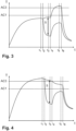
- Fig. 3 shows schematically a temperature-time curve that can be achieved by means of a method according to the invention.
- the temperature T of the metallic component or the temperatures T of the at least one first partial region and the at least one second partial region of the component are plotted against time t.
- the metallic component 1 is first heated uniformly to a temperature below the AC1 temperature until time t 1 .
- This heating takes place here, for example, in a first oven 2.
- the metallic component is transferred from the first oven to a tempering station.
- the component temperature can decrease slightly, for example due to heat being released into the environment.
- a first part of the component is cooled in the tempering station (actively).
- at least a second part of the component is heated (slightly) in the temperature control station.
- a temperature difference 5 is set between at least one first partial area and at least one second partial area of the component.
- the component is transferred from the tempering station to a second furnace that is different from the first furnace.
- the partially different temperatures set in the tempering station can decrease slightly, for example due to heat being released into the environment.
- the component is heated in the second furnace such that the temperature of the at least one first partial region of the component is increased by at least 150 K.
- the heating in the second furnace is carried out such that at the same time the temperature of the at least one second part of the component is brought to a temperature above the AC3 temperature.
- the component is transferred from the second furnace to a press hardening tool.
- the partially different temperatures set in the second furnace can decrease slightly, for example due to heat being released into the environment.
- the (entire) component is quenched in the press hardening tool.
- an at least partially or even predominantly martensitic structure can develop in the at least one second partial area of the component, which has a comparatively high strength and a comparatively low ductility.
- the at least one first partial area of the component essentially no structural transformation has taken place, since the at least one first partial area of the component has never exceeded the AC1 temperature at any time during the process, so that a predominantly ferritic structure remains in the at least one first partial area of the component, which has a comparatively low strength and a comparatively high ductility.
- Fig.4 shows schematically another temperature-time curve that can be achieved using a method not according to the invention.
- the metallic component is heated uniformly to a temperature above the AC3 temperature up to time t 1 . This heating takes place here, for example, in a first oven. Between times t 1 and t 2 , the metallic component is transferred from the first oven to a tempering station. The component temperature can decrease slightly during this process.
- a first part of the component is cooled in the tempering station (actively).
- the temperature of at least a second part of the component in the temperature control station can decrease slightly.
- This (passive) temperature decrease in the at least one second partial area of the component has a significantly lower cooling rate than the parallel (active) cooling of the at least one first partial area of the component.
- a temperature difference 5 is set between the at least one first partial area and at least one second partial area of the component.
- the component is transferred from the tempering station to a second oven that is different from the first oven.
- the partially different temperatures set in the tempering station can decrease slightly.
- the component is heated in the second furnace such that the temperature of the at least one first partial region of the component is increased by at least 150 K.
- the heating in the second furnace is carried out such that at the same time a cooling rate of the at least one second partial region of the component is reduced in comparison to a cooling rate during heat release to the environment.
- the component is transferred from the second furnace to a press hardening tool.
- the set partially different temperatures, for example due to heat loss to the environment.
- the (entire) component is quenched in the press hardening tool.
- an at least partially or even predominantly martensitic structure can develop in the at least one second partial area of the component, which has a comparatively high strength and a comparatively low ductility.
- an at least partially or even predominantly bainitic structure can develop, which has a comparatively low strength and a comparatively high ductility.
Landscapes
- Chemical & Material Sciences (AREA)
- Engineering & Computer Science (AREA)
- Physics & Mathematics (AREA)
- Thermal Sciences (AREA)
- Crystallography & Structural Chemistry (AREA)
- Mechanical Engineering (AREA)
- Materials Engineering (AREA)
- Metallurgy (AREA)
- Organic Chemistry (AREA)
- Heat Treatment Of Articles (AREA)
- Heat Treatments In General, Especially Conveying And Cooling (AREA)
Claims (4)
- Procédé de traitement thermique d'un composant métallique (1) avec au moins les étapes suivantes :a) le chauffage du composant (1) dans un premier four (7),b) le déplacement du composant (1) dans un poste de thermorégulation (8),c) le refroidissement par convection d'au moins une première zone partielle (2) du composant (1) dans le poste de thermorégulation (8) au moyen d'au moins une buse (3) qui évacue un courant de fluide (4) vers la première zone partielle (2), une différence de température (5) entre l'au moins une première zone partielle (2) et au moins une deuxième zone partielle (6) du composant (1) étant réglée et l'au moins une buse (3) étant exploitée avec une surpression d'au moins 2 bar, et, dans le poste de thermorégulation (8), en même temps ou au moins en partie parallèlement au refroidissement de l'au moins une première zone partielle (2) du composant (1), un apport d'énergie thermique étant effectué dans l'au moins une deuxième zone partielle (6) du composant (1),le composant (1) étant chauffé à l'étape a) à une température inférieure à la température AC3.
- Procédé selon la revendication 1, le procédé comprenant en outre au moins les étapes suivantes :d) le déplacement du composant (1) de la station de thermorégulation (8) dans un deuxième four (9),e) le chauffage au moins de la première zone partielle (2) du composant (1) dans le deuxième four (9) d'au moins 100 K.
- Procédé selon la revendication 1 ou 2, le procédé comprenant en outre au moins les étapes suivantes :f) le déplacement du composant (1) du poste de thermorégulation (8) ou du deuxième four (9) dans un outil de durcissement par compression (10),g) la mise en forme et le refroidissement du composant (1) dans l'outil de durcissement par compression (10).
- Procédé selon l'une quelconque des revendications 1 à 3, dans lequel l'au moins une première zone partielle (2) est refroidie par convection à une température inférieure à la température AC1 à l'étape c).
Applications Claiming Priority (6)
| Application Number | Priority Date | Filing Date | Title |
|---|---|---|---|
| DE102016201025.5A DE102016201025A1 (de) | 2016-01-25 | 2016-01-25 | Wärmebehandlungsverfahren und Wärmebehandlungsvorrichtung |
| DE102016201024.7A DE102016201024A1 (de) | 2016-01-25 | 2016-01-25 | Wärmebehandlungsverfahren und Wärmebehandlungsvorrichtung |
| DE102016201936.8A DE102016201936A1 (de) | 2016-02-09 | 2016-02-09 | Wärmebehandlungsverfahren und Wärmebehandlungsvorrichtung |
| DE102016202766.2A DE102016202766A1 (de) | 2016-02-23 | 2016-02-23 | Wärmebehandlungsverfahren und Wärmebehandlungsvorrichtung |
| DE102016118253.2A DE102016118253A1 (de) | 2016-09-27 | 2016-09-27 | Verfahren zur Wärmebehandlung eines metallischen Bauteils |
| PCT/EP2017/051508 WO2017129600A1 (fr) | 2016-01-25 | 2017-01-25 | Procede de traitement thermique d'un élément métallique |
Publications (3)
| Publication Number | Publication Date |
|---|---|
| EP3408420A1 EP3408420A1 (fr) | 2018-12-05 |
| EP3408420B1 true EP3408420B1 (fr) | 2024-06-26 |
| EP3408420C0 EP3408420C0 (fr) | 2024-06-26 |
Family
ID=57965904
Family Applications (1)
| Application Number | Title | Priority Date | Filing Date |
|---|---|---|---|
| EP17703343.8A Active EP3408420B1 (fr) | 2016-01-25 | 2017-01-25 | Procédé de traitement thermique d'un composant métallique |
Country Status (7)
| Country | Link |
|---|---|
| US (1) | US20190024203A1 (fr) |
| EP (1) | EP3408420B1 (fr) |
| CN (1) | CN109072330A (fr) |
| ES (1) | ES2982368T3 (fr) |
| HU (1) | HUE067310T2 (fr) |
| PL (1) | PL3408420T3 (fr) |
| WO (1) | WO2017129600A1 (fr) |
Families Citing this family (6)
| Publication number | Priority date | Publication date | Assignee | Title |
|---|---|---|---|---|
| DE102017120128A1 (de) * | 2017-09-01 | 2019-03-07 | Schwartz Gmbh | Verfahren zum Erwärmen eines metallischen Bauteils auf eine Zieltemperatur und entsprechender Rollenherdofen |
| EP3749791B1 (fr) * | 2018-02-06 | 2023-06-07 | Integrated Heat Treating Solutions, LLC | Trempe haute pression à uniformité instantanée pour contrôler les propriétés d'une pièce |
| DE102018109579A1 (de) * | 2018-04-20 | 2019-10-24 | Schwartz Gmbh | Temperiervorrichtung zur partiellen Kühlung eines Bauteils |
| CN109022722B (zh) * | 2018-07-23 | 2020-01-03 | 中国科学院金属研究所 | 一种高强度、高韧性犁柱的制造方法 |
| DE102020133462A1 (de) * | 2020-12-15 | 2022-06-15 | Schwartz Gmbh | Thermisches Behandeln von Bauteilen |
| DE102023135571A1 (de) * | 2023-12-18 | 2025-06-18 | Alexander Wilden Beteiligungen GmbH | Thermisches Behandeln eines metallischen Bauteils |
Citations (1)
| Publication number | Priority date | Publication date | Assignee | Title |
|---|---|---|---|---|
| US20030189027A1 (en) * | 2002-03-22 | 2003-10-09 | Benteler Automobiltechnik Gmbh | Method of making a metallic component |
Family Cites Families (10)
| Publication number | Priority date | Publication date | Assignee | Title |
|---|---|---|---|---|
| SE328324B (fr) * | 1965-11-24 | 1970-09-14 | Bethlehem Steel Corp | |
| DE10208216C1 (de) * | 2002-02-26 | 2003-03-27 | Benteler Automobiltechnik Gmbh | Verfahren zur Herstellung eines metallischen Bauteils |
| KR101277864B1 (ko) * | 2011-03-31 | 2013-06-21 | 주식회사 포스코 | 열간 성형용 블랭크 열처리 장치 및 열간 성형품 제조방법 |
| EP2548975A1 (fr) * | 2011-07-20 | 2013-01-23 | LOI Thermprocess GmbH | Procédé et dispositif de fabrication d'un composant métallique durci doté d'au moins deux zones ayant une ductilité différente |
| JP5380632B1 (ja) * | 2012-03-13 | 2014-01-08 | 株式会社アステア | 鋼板部材の強化方法 |
| DE102012218159B4 (de) * | 2012-10-04 | 2018-02-08 | Ebner Industrieofenbau Gmbh | Handhabungseinrichtung |
| KR101482336B1 (ko) * | 2012-12-21 | 2015-01-13 | 주식회사 포스코 | 이종 강도 영역을 갖는 열간 성형품의 제조방법 |
| DE102013104229B3 (de) * | 2013-04-25 | 2014-10-16 | N. Bättenhausen Industrielle Wärme- und Elektrotechnik GmbH | Vorrichtung zum Presshärten von Bauteilen |
| CN204474718U (zh) * | 2015-02-15 | 2015-07-15 | 赣州群星机器人有限公司 | 同步器齿套压力淬火机床 |
| CN204657935U (zh) * | 2015-05-18 | 2015-09-23 | 江西三川铜业有限公司 | 一种用于铜带加工的装置 |
-
2017
- 2017-01-25 EP EP17703343.8A patent/EP3408420B1/fr active Active
- 2017-01-25 PL PL17703343.8T patent/PL3408420T3/pl unknown
- 2017-01-25 ES ES17703343T patent/ES2982368T3/es active Active
- 2017-01-25 CN CN201780008164.0A patent/CN109072330A/zh active Pending
- 2017-01-25 HU HUE17703343A patent/HUE067310T2/hu unknown
- 2017-01-25 US US16/072,633 patent/US20190024203A1/en not_active Abandoned
- 2017-01-25 WO PCT/EP2017/051508 patent/WO2017129600A1/fr not_active Ceased
Patent Citations (1)
| Publication number | Priority date | Publication date | Assignee | Title |
|---|---|---|---|---|
| US20030189027A1 (en) * | 2002-03-22 | 2003-10-09 | Benteler Automobiltechnik Gmbh | Method of making a metallic component |
Also Published As
| Publication number | Publication date |
|---|---|
| CN109072330A (zh) | 2018-12-21 |
| PL3408420T3 (pl) | 2024-11-18 |
| HUE067310T2 (hu) | 2024-10-28 |
| ES2982368T3 (es) | 2024-10-15 |
| US20190024203A1 (en) | 2019-01-24 |
| WO2017129600A1 (fr) | 2017-08-03 |
| EP3408420C0 (fr) | 2024-06-26 |
| EP3408420A1 (fr) | 2018-12-05 |
Similar Documents
| Publication | Publication Date | Title |
|---|---|---|
| EP2864506B1 (fr) | Procédé et dispositif de fabrication d'un composant métallique trempé à la presse | |
| DE102011056444C5 (de) | Verfahren und Vorrichtung zum partiellen Härten von Blechbauteilen | |
| EP3652352B1 (fr) | Procédé et dispositif de traitement thermique d'une pièce métallique | |
| EP3408417B1 (fr) | Procédé de traitement thermique | |
| EP3408419A1 (fr) | Procédé et dispositif de traitement thermique d'une pièce métallique | |
| DE102016118252A1 (de) | Verfahren und Vorrichtung zur Wärmebehandlung eines metallischen Bauteils | |
| DE102017110864B3 (de) | Verfahren und Vorrichtung zum Erzeugen gehärteter Stahlblechbauteile mit unterschiedlichen Blechdicken | |
| EP3408420A1 (fr) | Procede de traitement thermique d'un élément métallique | |
| WO2015110456A1 (fr) | Dispositif de traitement thermique | |
| DE102016121699A1 (de) | Temperierstation zur partiellen Wärmebehandlung eines metallischen Bauteils | |
| EP3408416B1 (fr) | Procédé de traitement thermique et dispositif de traitement thermique | |
| EP3420111B1 (fr) | Procédé de traitement thermique ciblé sur les zones d'une pièce | |
| WO2017025460A1 (fr) | Procédé de traitement thermique d'un élément en tôle d'acier et dispositif de traitement thermique à cet effet | |
| EP3607098B1 (fr) | Poste de thermorégulation destiné au traitement thermique partiel d'une pièce métallique | |
| EP3414350B1 (fr) | Procédé de traitement thermique et utilisation d'un dispositif de traitement thermique | |
| DE102016124539B4 (de) | Verfahren zum Herstellen lokal gehärteter Stahlblechbauteile | |
| EP3408421B1 (fr) | Procédé et dispositif pour traitement thermique d'un composant en acier | |
| DE102016120605A1 (de) | Verfahren und Vorrichtung zur Wärmebehandlung eines metallischen Bauteils | |
| DE102016118253A1 (de) | Verfahren zur Wärmebehandlung eines metallischen Bauteils |
Legal Events
| Date | Code | Title | Description |
|---|---|---|---|
| STAA | Information on the status of an ep patent application or granted ep patent |
Free format text: STATUS: UNKNOWN |
|
| STAA | Information on the status of an ep patent application or granted ep patent |
Free format text: STATUS: THE INTERNATIONAL PUBLICATION HAS BEEN MADE |
|
| PUAI | Public reference made under article 153(3) epc to a published international application that has entered the european phase |
Free format text: ORIGINAL CODE: 0009012 |
|
| STAA | Information on the status of an ep patent application or granted ep patent |
Free format text: STATUS: REQUEST FOR EXAMINATION WAS MADE |
|
| 17P | Request for examination filed |
Effective date: 20180817 |
|
| AK | Designated contracting states |
Kind code of ref document: A1 Designated state(s): AL AT BE BG CH CY CZ DE DK EE ES FI FR GB GR HR HU IE IS IT LI LT LU LV MC MK MT NL NO PL PT RO RS SE SI SK SM TR |
|
| AX | Request for extension of the european patent |
Extension state: BA ME |
|
| DAV | Request for validation of the european patent (deleted) | ||
| DAX | Request for extension of the european patent (deleted) | ||
| STAA | Information on the status of an ep patent application or granted ep patent |
Free format text: STATUS: EXAMINATION IS IN PROGRESS |
|
| 17Q | First examination report despatched |
Effective date: 20200326 |
|
| P01 | Opt-out of the competence of the unified patent court (upc) registered |
Effective date: 20230516 |
|
| GRAP | Despatch of communication of intention to grant a patent |
Free format text: ORIGINAL CODE: EPIDOSNIGR1 |
|
| STAA | Information on the status of an ep patent application or granted ep patent |
Free format text: STATUS: GRANT OF PATENT IS INTENDED |
|
| RIC1 | Information provided on ipc code assigned before grant |
Ipc: C21D 1/84 20060101ALI20240216BHEP Ipc: C21D 1/673 20060101ALI20240216BHEP Ipc: C21D 1/19 20060101ALI20240216BHEP Ipc: C21D 9/46 20060101ALI20240216BHEP Ipc: C21D 1/667 20060101ALI20240216BHEP Ipc: C21D 9/00 20060101AFI20240216BHEP |
|
| INTG | Intention to grant announced |
Effective date: 20240320 |
|
| GRAS | Grant fee paid |
Free format text: ORIGINAL CODE: EPIDOSNIGR3 |
|
| GRAA | (expected) grant |
Free format text: ORIGINAL CODE: 0009210 |
|
| STAA | Information on the status of an ep patent application or granted ep patent |
Free format text: STATUS: THE PATENT HAS BEEN GRANTED |
|
| AK | Designated contracting states |
Kind code of ref document: B1 Designated state(s): AL AT BE BG CH CY CZ DE DK EE ES FI FR GB GR HR HU IE IS IT LI LT LU LV MC MK MT NL NO PL PT RO RS SE SI SK SM TR |
|
| REG | Reference to a national code |
Ref country code: GB Ref legal event code: FG4D Free format text: NOT ENGLISH |
|
| REG | Reference to a national code |
Ref country code: CH Ref legal event code: EP |
|
| REG | Reference to a national code |
Ref country code: DE Ref legal event code: R096 Ref document number: 502017016202 Country of ref document: DE |
|
| U01 | Request for unitary effect filed |
Effective date: 20240705 |
|
| U07 | Unitary effect registered |
Designated state(s): AT BE BG DE DK EE FI FR IT LT LU LV MT NL PT SE SI Effective date: 20240716 |
|
| P04 | Withdrawal of opt-out of the competence of the unified patent court (upc) registered |
Free format text: CASE NUMBER: APP_41240/2024 Effective date: 20240712 |
|
| PG25 | Lapsed in a contracting state [announced via postgrant information from national office to epo] |
Ref country code: HR Free format text: LAPSE BECAUSE OF FAILURE TO SUBMIT A TRANSLATION OF THE DESCRIPTION OR TO PAY THE FEE WITHIN THE PRESCRIBED TIME-LIMIT Effective date: 20240626 |
|
| PG25 | Lapsed in a contracting state [announced via postgrant information from national office to epo] |
Ref country code: GR Free format text: LAPSE BECAUSE OF FAILURE TO SUBMIT A TRANSLATION OF THE DESCRIPTION OR TO PAY THE FEE WITHIN THE PRESCRIBED TIME-LIMIT Effective date: 20240927 |
|
| REG | Reference to a national code |
Ref country code: ES Ref legal event code: FG2A Ref document number: 2982368 Country of ref document: ES Kind code of ref document: T3 Effective date: 20241015 |
|
| REG | Reference to a national code |
Ref country code: HU Ref legal event code: AG4A Ref document number: E067310 Country of ref document: HU |
|
| PG25 | Lapsed in a contracting state [announced via postgrant information from national office to epo] |
Ref country code: NO Free format text: LAPSE BECAUSE OF FAILURE TO SUBMIT A TRANSLATION OF THE DESCRIPTION OR TO PAY THE FEE WITHIN THE PRESCRIBED TIME-LIMIT Effective date: 20240926 Ref country code: HR Free format text: LAPSE BECAUSE OF FAILURE TO SUBMIT A TRANSLATION OF THE DESCRIPTION OR TO PAY THE FEE WITHIN THE PRESCRIBED TIME-LIMIT Effective date: 20240626 Ref country code: GR Free format text: LAPSE BECAUSE OF FAILURE TO SUBMIT A TRANSLATION OF THE DESCRIPTION OR TO PAY THE FEE WITHIN THE PRESCRIBED TIME-LIMIT Effective date: 20240927 Ref country code: RS Free format text: LAPSE BECAUSE OF FAILURE TO SUBMIT A TRANSLATION OF THE DESCRIPTION OR TO PAY THE FEE WITHIN THE PRESCRIBED TIME-LIMIT Effective date: 20240926 |
|
| P05 | Withdrawal of opt-out of the competence of the unified patent court (upc) changed |
Free format text: CASE NUMBER: APP_41240/2024 Effective date: 20240716 |
|
| PG25 | Lapsed in a contracting state [announced via postgrant information from national office to epo] |
Ref country code: IS Free format text: LAPSE BECAUSE OF FAILURE TO SUBMIT A TRANSLATION OF THE DESCRIPTION OR TO PAY THE FEE WITHIN THE PRESCRIBED TIME-LIMIT Effective date: 20241026 |
|
| PG25 | Lapsed in a contracting state [announced via postgrant information from national office to epo] |
Ref country code: RO Free format text: LAPSE BECAUSE OF FAILURE TO SUBMIT A TRANSLATION OF THE DESCRIPTION OR TO PAY THE FEE WITHIN THE PRESCRIBED TIME-LIMIT Effective date: 20240626 Ref country code: SK Free format text: LAPSE BECAUSE OF FAILURE TO SUBMIT A TRANSLATION OF THE DESCRIPTION OR TO PAY THE FEE WITHIN THE PRESCRIBED TIME-LIMIT Effective date: 20240626 |
|
| PG25 | Lapsed in a contracting state [announced via postgrant information from national office to epo] |
Ref country code: SM Free format text: LAPSE BECAUSE OF FAILURE TO SUBMIT A TRANSLATION OF THE DESCRIPTION OR TO PAY THE FEE WITHIN THE PRESCRIBED TIME-LIMIT Effective date: 20240626 |
|
| PG25 | Lapsed in a contracting state [announced via postgrant information from national office to epo] |
Ref country code: SM Free format text: LAPSE BECAUSE OF FAILURE TO SUBMIT A TRANSLATION OF THE DESCRIPTION OR TO PAY THE FEE WITHIN THE PRESCRIBED TIME-LIMIT Effective date: 20240626 Ref country code: SK Free format text: LAPSE BECAUSE OF FAILURE TO SUBMIT A TRANSLATION OF THE DESCRIPTION OR TO PAY THE FEE WITHIN THE PRESCRIBED TIME-LIMIT Effective date: 20240626 Ref country code: RO Free format text: LAPSE BECAUSE OF FAILURE TO SUBMIT A TRANSLATION OF THE DESCRIPTION OR TO PAY THE FEE WITHIN THE PRESCRIBED TIME-LIMIT Effective date: 20240626 Ref country code: IS Free format text: LAPSE BECAUSE OF FAILURE TO SUBMIT A TRANSLATION OF THE DESCRIPTION OR TO PAY THE FEE WITHIN THE PRESCRIBED TIME-LIMIT Effective date: 20241026 |
|
| U20 | Renewal fee for the european patent with unitary effect paid |
Year of fee payment: 9 Effective date: 20250128 |
|
| PLBE | No opposition filed within time limit |
Free format text: ORIGINAL CODE: 0009261 |
|
| STAA | Information on the status of an ep patent application or granted ep patent |
Free format text: STATUS: NO OPPOSITION FILED WITHIN TIME LIMIT |
|
| 26N | No opposition filed |
Effective date: 20250327 |
|
| REG | Reference to a national code |
Ref country code: CH Ref legal event code: PL |
|
| PG25 | Lapsed in a contracting state [announced via postgrant information from national office to epo] |
Ref country code: MC Free format text: LAPSE BECAUSE OF FAILURE TO SUBMIT A TRANSLATION OF THE DESCRIPTION OR TO PAY THE FEE WITHIN THE PRESCRIBED TIME-LIMIT Effective date: 20240626 |
|
| GBPC | Gb: european patent ceased through non-payment of renewal fee |
Effective date: 20250125 |
|
| PG25 | Lapsed in a contracting state [announced via postgrant information from national office to epo] |
Ref country code: GB Free format text: LAPSE BECAUSE OF NON-PAYMENT OF DUE FEES Effective date: 20250125 |
|
| PG25 | Lapsed in a contracting state [announced via postgrant information from national office to epo] |
Ref country code: CH Free format text: LAPSE BECAUSE OF NON-PAYMENT OF DUE FEES Effective date: 20250131 |
|
| PG25 | Lapsed in a contracting state [announced via postgrant information from national office to epo] |
Ref country code: IE Free format text: LAPSE BECAUSE OF NON-PAYMENT OF DUE FEES Effective date: 20250125 |
|
| PGFP | Annual fee paid to national office [announced via postgrant information from national office to epo] |
Ref country code: HU Payment date: 20260123 Year of fee payment: 10 |
|
| U20 | Renewal fee for the european patent with unitary effect paid |
Year of fee payment: 10 Effective date: 20260129 |
|
| PGFP | Annual fee paid to national office [announced via postgrant information from national office to epo] |
Ref country code: ES Payment date: 20260227 Year of fee payment: 10 |
|
| PGFP | Annual fee paid to national office [announced via postgrant information from national office to epo] |
Ref country code: CZ Payment date: 20260120 Year of fee payment: 10 |
|
| PGFP | Annual fee paid to national office [announced via postgrant information from national office to epo] |
Ref country code: PL Payment date: 20260102 Year of fee payment: 10 |