EP3408480B1 - Kabel für kraftfahrzeugtürschloss - Google Patents
Kabel für kraftfahrzeugtürschloss Download PDFInfo
- Publication number
- EP3408480B1 EP3408480B1 EP17706290.8A EP17706290A EP3408480B1 EP 3408480 B1 EP3408480 B1 EP 3408480B1 EP 17706290 A EP17706290 A EP 17706290A EP 3408480 B1 EP3408480 B1 EP 3408480B1
- Authority
- EP
- European Patent Office
- Prior art keywords
- cable
- piece
- distance
- cable end
- sheath
- Prior art date
- Legal status (The legal status is an assumption and is not a legal conclusion. Google has not performed a legal analysis and makes no representation as to the accuracy of the status listed.)
- Active
Links
Images

Classifications
-
- E—FIXED CONSTRUCTIONS
- E05—LOCKS; KEYS; WINDOW OR DOOR FITTINGS; SAFES
- E05B—LOCKS; ACCESSORIES THEREFOR; HANDCUFFS
- E05B79/00—Mounting or connecting vehicle locks or parts thereof
- E05B79/10—Connections between movable lock parts
- E05B79/20—Connections between movable lock parts using flexible connections, e.g. Bowden cables
-
- F—MECHANICAL ENGINEERING; LIGHTING; HEATING; WEAPONS; BLASTING
- F16—ENGINEERING ELEMENTS AND UNITS; GENERAL MEASURES FOR PRODUCING AND MAINTAINING EFFECTIVE FUNCTIONING OF MACHINES OR INSTALLATIONS; THERMAL INSULATION IN GENERAL
- F16C—SHAFTS; FLEXIBLE SHAFTS; ELEMENTS OR CRANKSHAFT MECHANISMS; ROTARY BODIES OTHER THAN GEARING ELEMENTS; BEARINGS
- F16C1/00—Flexible shafts; Mechanical means for transmitting movement in a flexible sheathing
- F16C1/10—Means for transmitting linear movement in a flexible sheathing, e.g. "Bowden-mechanisms"
- F16C1/102—Arrangements to mount end fittings of the sheathings to support walls or brackets
-
- F—MECHANICAL ENGINEERING; LIGHTING; HEATING; WEAPONS; BLASTING
- F16—ENGINEERING ELEMENTS AND UNITS; GENERAL MEASURES FOR PRODUCING AND MAINTAINING EFFECTIVE FUNCTIONING OF MACHINES OR INSTALLATIONS; THERMAL INSULATION IN GENERAL
- F16C—SHAFTS; FLEXIBLE SHAFTS; ELEMENTS OR CRANKSHAFT MECHANISMS; ROTARY BODIES OTHER THAN GEARING ELEMENTS; BEARINGS
- F16C2350/00—Machines or articles related to building
- F16C2350/52—Locks, e.g. cables to actuate door locks
Definitions
- the invention relates to a cable for a lock intended to open and lock a door leaf of a motor vehicle.
- This type of cable includes in particular transmission cables and connection to the handles for actuating the lock to open the door.
- lock cable is meant in particular an assembly comprising for example an opening cable and a cable for locking the opening.
- the invention further relates to a motor vehicle lock receiving the cable according to the invention, and an opening and locking assembly as well as a corresponding motor vehicle.
- Locks generally comprise a housing fixed to a mounting part making it possible to mount a motor vehicle lock cable.
- Each cable is associated with a lever provided in the box.
- the cable includes a cable sheath and a cable core terminating in a cable end at each end of the sheath.
- the end of the sheath is attached to a mounting piece, also called a "sheath end piece", and the mounting piece houses the cable end piece.
- the invention aims to provide a cable and a lock whose assembly is simplified and the assembly times are reduced compared to the prior art, so as to reduce the assembly costs.
- the cable according to the invention provides for maintaining the cable end piece in the delivery position, which makes it possible to preserve the position of the cable end piece from the vibrations undergone during transport to the construction line.
- the cable, delivered separately from the lock, according to the invention therefore makes it possible to limit the transport costs.
- deactivation of the holding means makes it possible to associate the cable with the lock housing by making the cable end-piece and the corresponding lever cooperate.
- the cable according to the invention therefore has a simplified assembly with limited assembly costs.
- the invention further relates to a lock for opening and locking an opening of a motor vehicle comprising a housing intended to receive the cable according to the invention, the housing and the cable comprising attachment means for fixing the housing and the cable, the housing comprising a lever configured to cooperate with the cable end piece when the housing is attached to the cable via the attachment means.
- the invention also relates to an assembly for opening and locking a motor vehicle opening comprising a lock for opening and locking an opening and a cable according to the invention.
- the invention further relates to a motor vehicle comprising an opening and locking assembly according to the invention.
- the cable is mounted so as to close a lower face of the case with reference to the motor vehicle.
- the present invention relates to a cable for a lock intended to open and lock a door leaf of a motor vehicle such as a side door or a rear flap.
- the cable is generally noted 1.
- the cable 1 is an assembly comprising for example an opening cable 10 and a locking cable 20. The description below is based on the opening cable 10.
- the locking cable 20 a preferably characteristics identical to those of the opening cable 10, unless otherwise stated.
- the opening cable 10 comprises a cable sheath 12 and a cable core 11a movably housed in the sheath 12.
- the cable core 11a ends in a cable end 11 at at least one end of the sheath, for example at the end of the sheath 12 on the figure 1 .
- the cable core 11a ends in a cable end piece at each end of the sheath 12.
- the locking cable 20 also includes another sheath 22 and another cable core 21a.
- the cable 1 also comprises a mounting part 4 fixed to said end of the sheath 12.
- the mounting part 4 houses the cable end 11.
- the cable end piece 11 is mounted movable between a delivery position and an operating position.
- the cable end piece 11 is placed in a delivery area b at a first distance from said end of the sheath 12.
- the cable end 11 is placed in an operating zone c at a second distance from said end of the sheath 12.
- the mounting piece 4 further comprises a means 41 for holding the cable end 11 in the delivery position.
- the cable 1 according to the invention provides for holding the cable end 11 in the delivery position, by the holding means 41.
- the holding means 41 makes it possible to preserve the position of the cable 1 against the vibrations undergone during transport to a construction line.
- deactivation of the holding means 41 makes it possible to associate the opening cable 10 with the lock housing by making the cable end 11 and the lever cooperate. corresponding, in particular by a so-called “blind” assembly, that is to say without the need for visual control to associate the cable end piece 11 with the corresponding lever.
- the cable 1 according to the invention therefore has a simplified assembly with limited assembly costs.
- the holding means 41 is deactivated by unclipping so that the cable end 11 can be placed in the operating position.
- unclipping of two elements at least partially coupled together, is meant a dislocation of said elements involving plastic or elastic deformation of a sub-element involved in the coupling of said elements. An elastic deformation allows reversible unclipping.
- the holding means 41 comprises a deforming element to allow the cable end 11 to be moved from the delivery position to the operating position.
- the cable end piece 11 is further mounted movable to or from a mounting position in which the cable end piece 11 is disposed in a mounting area a at another distance from said end of the sheath 12, so that the second distance is between the first distance and the other distance.
- the mounting area a configured so that the operating area c is between the mounting area a and the delivery area b.
- this arrangement makes it possible to guarantee easy assembly of the end piece and without risk of dismantling during use, in particular thanks to the position of the mounting zone outside the operating zone.
- the holding means 41 retains the cable endpiece in the delivery position by clipping.
- clipping of two elements is meant an at least partial nesting of said elements involving a deformation, preferably elastic, of a sub-element of at least one of said elements.
- the holding means 41 comprises an elastically deforming element to dispose the cable end 11 in the delivery position. Said element returning to its initial shape maintains the cable end 11 in the delivery position.
- a holding means 41 comprises a holding blade.
- this embodiment offers a simple, effective and low-cost means for maintaining the cable end piece in the delivery position.
- the holding means 41 can for example be obtained by a specific molding of the mounting piece 4.
- the holding blade is preferably the portion deforming plastically or elastically.
- the cable end piece 11 is mounted movable in translation between said positions.
- the cable end piece 11 is mounted movable between at least two of said positions.
- a translation is a simple movement of the cable end piece linked to the pulling of the cable without requiring a complex mechanism such as a cam.
- the mounting part 4 comprises a guide means 51 for the cable end 11 in the operating zone c.
- the guide means makes it possible to maintain a constant trajectory of the cable end piece 11 between the different positions.
- the guide means 51 is a guide rail cooperating with the cable end piece 11.
- the guide means 51 can for example be obtained by specific molding of the mounting part 4.
- the cable end 11 comprises at least one guide structure 11b, for example a shoulder, cooperating with the guide rail 51.
- the opening cable 10 is mounted so that in the delivery position, the cable end 11 is disposed at a first distance greater than the second distance from the operating position. This arrangement is better suited to an opening cable.
- the locking cable 20 is mounted so that in the delivery position, the cable end piece 21 is disposed at a first distance less than the second distance from the operating position. This arrangement is better suited to a locking cable.
- the locking cable 20 configured so that a movement of the cable end piece 21 makes it possible to deactivate the means of holding 42 and moving the cable end piece 21 from the delivery position to the operating position.
- the cable end piece 21 and the holding means 42 are configured so that a thrust exerted on the cable end piece 21 allows it to come out of the delivery position to reach the operating position.
- This arrangement makes it possible to have a first simplified and low-cost means for deactivating the holding means 42.
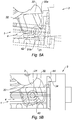
- the surfaces of the cable end piece 21 and the holding means 42 comprise at least one circular part and the holding means 42 preferably comprises an angled portion so that a thrust exerted to the left of the Figures 5A and 5B allows to move the holding means down of said figures and to slide the cable end piece 21 towards the operating position.
- This arrangement is particularly suitable for a locking cable, since the cable end piece is motor both in pushing and in pulling.
- the opening cable 10 is configured so that a pull of the cable core 11a makes it possible to deactivate the holding means 41 and to move the cable end 11 from the position of delivery to operating position.
- This arrangement makes it possible to have a second simplified and low-cost means for deactivating the holding means 41.
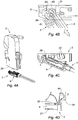
- the cable end 11 mounted at a certain distance from the corresponding lever 31, the association with said lever 31 is made by pulling the cable core to the right of the Figures 4B and 4C .
- This arrangement is particularly suitable for an opening cable, because the cable end piece is initially disposed at a distance from the cable end piece 11 and is intended to come closer to it, preferably come into contact, in order to reach the position of operation.
- the invention further relates to a lock for opening and locking an opening of a motor vehicle comprising a housing 3 intended to receive the cable 1 according to the invention.
- the housing 3 and the cable 1 comprise detailed attachment means marked 33, 43, 34 and 44 for fixing the housing 3 and the cable 1.
- the housing 3 comprises an opening lever 31 and preferably a locking lever 32 configured to cooperate respectively with the cable end 11 and the cable end 21 when the housing is attached to the cable 1 via said attachment means.
- the housing 3 preferably comprises a first 33 and a second 34 attachment means
- the cable 1 comprises a first 43 and a second 44 attachment means configured to cooperate respectively with the attachment means 33, 34 of the housing 3.
- the lock comprises a drive structure 32a configured to deactivate the holding means 42 and to move the cable end piece 21 from the delivery position to the operating position.
- the drive structure 32a is a ramp of the locking lever 32 active when the case is attached to the cable 1 via said attachment means.
- the attachment means comprise on the one hand a fastening system by hook with rotary hinge 33, 43 and on the other hand a fastening system by clipping 34, 44.
- opening lever 31 and preferably the locking lever 32 are configured to cooperate respectively with the cable end 11 and the cable end 21 when the housing 3 is attached to the cable 1 via the fastening system with rotary hinge hook 33, 43 and clip fastening system 34, 44.
- the first attachment means comprise the rotary hinge hook 33, 43.
- the cable 1 comprises the male structure of the rotary hinge hook and the housing 3 comprises the female structure.
- a reverse variant can be envisaged.
- the second attachment means comprise the attachment system by clipping 34, 44.
- the cable 1 comprises a protrusion for clipping said attachment structure
- the housing 3 comprises a relief of clipping receiving said clipping protuberance as can be seen on the figure 4D .
- a reverse variant can be envisaged.
- the cable 1 and / or the housing 3 comprises sealing means 45 so that the cable 1 partitions the housing 3 when the cable 1 is mounted on the housing 3.
- the sealing means 45 may comprise at least one seal provided on the cable 1, in particular on the mounting part 4.
- the lock comprises a keying arrangement 36 configured to fix the housing 3 and the cable 1 and associate the opening lever 31 and preferably the locking lever 32 and respectively the end piece cable 11 and the cable end 21.
- the keying arrangement 36 comprises a funnel shape provided on the housing.
- the funnel shape is open and widened towards the bottom of the Figures 4A to 4D so that an insertion of the cable 1 towards the top of the said figures allows the cable 1 to be placed in the required position without the need for visual inspection.
- the keying arrangement 36 is preferably asymmetrical and makes it possible to prevent the mounting of a right door cable on a left door lock and vice versa.
- the invention further relates to an opening and locking assembly of a motor vehicle opening comprising a lock for opening and locking an opening and a cable 1 according to the invention.
- the lock of the assembly is also a lock according to the invention.
- the invention also relates to a motor vehicle comprising an opening and locking assembly according to the invention.
- the cable 1 is mounted so as to close a lower face of the housing 3 with reference to the motor vehicle. This aspect increases the protection of the lock against water intrusion into the lock.
- the mounting of the cable 1 in the lock comprises a first mounting i of the first attachment means 33, 43 then a second mounting ii of the second attachment means 34, 44.
- the first attachment means 33, 43 are associated together, in particular the male structure is inserted in the female structure of the rotating hinge hook. The hinge is then pivoted to fix the cable to the lock.
- the second attachment means 34, 44 are associated together, in particular the protuberance of the attachment system by clipping is associated with the clipping relief as can be seen on the figure 4D .
- the pivoting of the hinge makes it possible to associate the second attachment means 34, 44, in particular of the attachment system by clipping as can be seen on the Figures 4C and 4D .
- the second mounting ii therefore comprises the pivoting of the hinge in a preferred variant, which allows rapid mounting.
- levers 31, 32 in the housing 3 allows their association with the respective cable ends 11, 12, which allows mounting without visual inspection.
- mounting the cable 1 in the housing 3 allows the locking lever 32 comprising the drive structure 32a to move the cable end piece 21 towards the operating position while associating said cable end piece 21 with said locking lever 32.
- mounting the cable 1 in the housing 3 makes it possible to position the cable end 11 near the opening lever 31 so that a pull of the cable core 11a makes it possible to associate said cable end with said lever d opening 31.
- This arrangement allows the cable ends 11, 21 to be associated with the corresponding levers 31, 32 without visual inspection.
- a cable 1 preferably comprising an opening cable and a locking cable.
- the invention also covers a system in which only the opening cable or the locking cable is as described above.
Landscapes
- Engineering & Computer Science (AREA)
- General Engineering & Computer Science (AREA)
- Health & Medical Sciences (AREA)
- Oral & Maxillofacial Surgery (AREA)
- Mechanical Engineering (AREA)
- Lock And Its Accessories (AREA)
Claims (15)
- Kabel (1) für ein Schloss, das dazu bestimmt ist, eine Tür eines Kraftfahrzeugs zu öffnen und zu verriegeln, wobei das Kabel (1) einen Kabelmantel (12, 22) und einen Kabelkern (11a, 21a) umfasst, der beweglich in dem Mantel (12, 22) untergebracht ist, wobei der Kabelkern (11a, 21a) an mindestens einem Ende des Mantels (12, 22) mit einem Kabelendstück (11, 21) abschließt,
wobei das Kabel weiter ein Befestigungsteil (4) umfasst, das an dem Ende des Mantels (12, 22) fixiert ist, wobei das Befestigungsteil (4) das Kabelendstück (11, 21) unterbringt,
wobei das Kabelendstück (11, 21) beweglich befestigt ist zwischen- einer Lieferposition, in der das Kabelendstück (11, 21) in einer Lieferzone (b) in einem ersten Abstand zu dem Ende des Mantels (12, 22) angeordnet ist, und- einer Betriebsposition, in der das Kabelendstück (11, 21) in einer Betriebszone (c) in einem zweiten Abstand zu dem Ende des Mantels (12, 22) angeordnet ist,und wobei das Befestigungsteil (4) weiter ein Haltemittel (41, 42) des Kabelendstücks (11, 21) in der Lieferposition umfasst. - Kabel (1) nach dem vorstehenden Anspruch, wobei das Kabelendstück (11, 21) weiter in eine oder aus einer Befestigungsposition beweglich befestigt ist, in der das Kabelendstück (11, 21) in einer Befestigungszone (a) in einem anderen Abstand zu dem Ende des Mantels (12, 22) angeordnet ist, sodass der zweite Abstand zwischen dem ersten Abstand und dem anderen Abstand enthalten ist.
- Kabel (1) nach einem der vorstehenden Ansprüche, wobei das Haltemittel (41, 42) eine Halteleiste umfasst.
- Kabel (1) nach einem der vorstehenden Ansprüche, wobei das Kabelendstück (11, 21) translationsbeweglich zwischen den Positionen befestigt ist.
- Kabel (1) nach einem der vorstehenden Ansprüche, wobei das Befestigungsteil (4) ein Führungsmittel (51, 52) des Kabelendstücks in der Betriebszone (c) umfasst.
- Kabel (1) nach einem der vorstehenden Ansprüche, wobei das Führungsmittel (51, 52) eine Führungsschiene ist, die mit dem Kabelendstück (11, 21) zusammenwirkt.
- Kabel (1) nach einem der vorstehenden Ansprüche, wobei das Kabel (1) derart befestigt ist, dass das Kabelendstück (11) in Lieferposition in einem ersten Abstand größer als der zweite Abstand von der Betriebsposition angeordnet ist.
- Kabel (1) nach einem der vorstehenden Ansprüche, wobei das Kabel (1) derart befestigt ist, dass das Kabelendstück (21) in Lieferposition in einem ersten Abstand kleiner als der zweite Abstand von der Betriebsposition angeordnet ist.
- Kabel (1) nach einem der vorstehenden Ansprüche, wobei das Kabel (1) derart konfiguriert ist, dass eine Verschiebung des Kabelendstücks (21) erlaubt, das Haltemittel (42) zu deaktivieren, und das Kabelendstück (21) von der Lieferposition in die Betriebsposition zu verschieben.
- Kabel (1) nach einem der vorstehenden Ansprüche, wobei das Kabel (1) derart konfiguriert ist, dass ein Ziehen des Kabelkerns (11a) erlaubt, das Haltemittel (41) zu deaktivieren und das Kabelendstück (11) von der Lieferposition in die Betriebsposition zu verschieben.
- Schloss zum Öffnen und Verriegeln einer Tür eines Kraftfahrzeugs, umfassend ein Gehäuse (3), welches das Kabel (1) nach einem der vorstehenden Ansprüche aufnimmt,
wobei das Gehäuse (3) und das Kabel (1) Verbindungsmittel (33, 43, 34, 44) zum Fixieren des Gehäuses und des Kabels (1) umfassen,
wobei das Gehäuse (3) einen Hebel (31, 32) umfasst, der konfiguriert ist, um mit dem Kabelendstück (11, 21) zusammenzuwirken, wenn das Gehäuse anhand der Verbindungsmittel (33, 43, 34, 44) mit dem Kabel (1) verbunden ist. - Schloss nach dem vorstehenden Anspruch, umfassend eine Antriebsstruktur (32a), die konfiguriert ist, um das Haltemittel (42) zu deaktivieren und um das Kabelendstück (21) von der Lieferposition in die Betriebsposition zu verschieben.
- Schloss nach dem vorstehenden Anspruch, wobei die Antriebsstruktur (32a) eine aktive Rampe des Hebels (32) ist, wenn das Gehäuse anhand der Verbindungsmittel (33, 43, 34, 44) mit dem Kabel (1) verbunden ist.
- Schloss nach einem der Ansprüche 11 bis 13, wobei die Verbindungsmittel (33, 43, 34, 44) einerseits ein Verbindungssystem durch Haken mit Drehscharnier (33, 43), und andererseits ein Verbindungssystem durch Kopplung (34, 44) umfassen,
und wobei der Hebel (31, 32) konfiguriert ist, um mit dem Kabelendstück (11, 21) zusammenzuwirken, wenn das Gehäuse (3) anhand des Verbindungssystems durch Haken mit Drehscharnier (33, 43) und des Verbindungssystems durch Kopplung (34, 44) mit dem Kabel (1) verbunden ist. - Schloss nach einem der Ansprüche 11 bis 14, wobei das Kabel (1) und/oder das Gehäuse Dichtmittel (45) umfasst, sodass das Kabel (1) das Gehäuse (3) unterteilt, wenn das Kabel (1) auf dem Gehäuse (3) befestigt ist.
Applications Claiming Priority (2)
| Application Number | Priority Date | Filing Date | Title |
|---|---|---|---|
| FR1650692A FR3047266B1 (fr) | 2016-01-28 | 2016-01-28 | Cable pour serrure d’ouvrant de vehicule automobile |
| PCT/FR2017/050175 WO2017129905A1 (fr) | 2016-01-28 | 2017-01-26 | Câble pour serrure d'ouvrant de véhicule automobile |
Publications (2)
| Publication Number | Publication Date |
|---|---|
| EP3408480A1 EP3408480A1 (de) | 2018-12-05 |
| EP3408480B1 true EP3408480B1 (de) | 2019-12-25 |
Family
ID=56117835
Family Applications (1)
| Application Number | Title | Priority Date | Filing Date |
|---|---|---|---|
| EP17706290.8A Active EP3408480B1 (de) | 2016-01-28 | 2017-01-26 | Kabel für kraftfahrzeugtürschloss |
Country Status (5)
| Country | Link |
|---|---|
| EP (1) | EP3408480B1 (de) |
| JP (1) | JP6913098B2 (de) |
| CN (1) | CN108603388B (de) |
| FR (1) | FR3047266B1 (de) |
| WO (1) | WO2017129905A1 (de) |
Cited By (1)
| Publication number | Priority date | Publication date | Assignee | Title |
|---|---|---|---|---|
| US20240344370A1 (en) * | 2023-03-16 | 2024-10-17 | Magna Closures Inc. | Blind connection system for a remote actuator |
Families Citing this family (2)
| Publication number | Priority date | Publication date | Assignee | Title |
|---|---|---|---|---|
| DE102019100986B4 (de) | 2018-01-17 | 2026-02-19 | Bayerische Motoren Werke Aktiengesellschaft | Schließeinrichtung, Bowdenzug, Fahrzeug und Verfahren zur Bowdenzugmontage |
| JP7290617B2 (ja) * | 2020-09-08 | 2023-06-13 | トヨタ自動車株式会社 | 車両、及び、車両の生産方法 |
Family Cites Families (9)
| Publication number | Priority date | Publication date | Assignee | Title |
|---|---|---|---|---|
| JP2573895B2 (ja) * | 1992-01-31 | 1997-01-22 | 株式会社大井製作所 | 自動車用ドアロック装置 |
| JP2528945Y2 (ja) * | 1992-02-28 | 1997-03-12 | 株式会社大井製作所 | 自動車用ドアロック装置 |
| DE10227873A1 (de) * | 2002-06-22 | 2004-01-08 | Bayerische Motoren Werke Ag | Bowdenzug mit einem gekrümmten Führungsteil |
| FR2984938B1 (fr) * | 2011-12-21 | 2017-03-10 | Valeo Securite Habitacle | Serrure pour vehicule automobile |
| DE102013203166B4 (de) * | 2013-02-26 | 2020-01-30 | Kiekert Ag | Bowdenzug |
| JP6131103B2 (ja) * | 2013-05-24 | 2017-05-17 | 株式会社アルファ | 車両用ハンドル装置 |
| JP6368951B2 (ja) * | 2014-03-13 | 2018-08-08 | 三井金属アクト株式会社 | 車両用ドアラッチ装置 |
| JP6306415B2 (ja) * | 2014-04-22 | 2018-04-04 | 株式会社アルファ | 車両のハンドル装置 |
| JP2016008021A (ja) * | 2014-06-26 | 2016-01-18 | ヤマハ発動機株式会社 | 車両 |
-
2016
- 2016-01-28 FR FR1650692A patent/FR3047266B1/fr not_active Expired - Fee Related
-
2017
- 2017-01-26 JP JP2018539841A patent/JP6913098B2/ja active Active
- 2017-01-26 EP EP17706290.8A patent/EP3408480B1/de active Active
- 2017-01-26 CN CN201780008481.2A patent/CN108603388B/zh active Active
- 2017-01-26 WO PCT/FR2017/050175 patent/WO2017129905A1/fr not_active Ceased
Non-Patent Citations (1)
| Title |
|---|
| None * |
Cited By (1)
| Publication number | Priority date | Publication date | Assignee | Title |
|---|---|---|---|---|
| US20240344370A1 (en) * | 2023-03-16 | 2024-10-17 | Magna Closures Inc. | Blind connection system for a remote actuator |
Also Published As
| Publication number | Publication date |
|---|---|
| WO2017129905A1 (fr) | 2017-08-03 |
| FR3047266A1 (fr) | 2017-08-04 |
| FR3047266B1 (fr) | 2018-05-18 |
| CN108603388B (zh) | 2020-11-03 |
| EP3408480A1 (de) | 2018-12-05 |
| JP2019504949A (ja) | 2019-02-21 |
| JP6913098B2 (ja) | 2021-08-04 |
| CN108603388A (zh) | 2018-09-28 |
Similar Documents
| Publication | Publication Date | Title |
|---|---|---|
| EP1882779B1 (de) | Vorrichtung zum Verriegeln und Entriegeln einer Abdeckung oder eines Deckels auf einem Rahmen mit Hilfe eines Schlüssels, insbesondere von Fahrbahnschachtabdeckungen | |
| EP3408480B1 (de) | Kabel für kraftfahrzeugtürschloss | |
| FR2937670A1 (fr) | Systeme de trappe. | |
| EP1105583B1 (de) | Sperrvorrichtung mit selektiver verriegelung | |
| EP0647752B1 (de) | Entkuppelbares Schloss für Kraftfahrzeuge und dgl. | |
| FR2876077A1 (fr) | Methode de montage d'un dispositif de commande interieur du mecanisme d'ouverture d'un ouvrant de vehicule automobile, piece intermediaire de prepositionnement utilise dans la methode, et ouvrant obtenu par cette methode | |
| FR2761422A1 (fr) | Dispositif de fixation d'un element quelconque, tel qu'une poignee, sur une paroi | |
| EP2318622B1 (de) | Vorrichtung zum vorübergehenden schliessen einer zu öffnenden platte auf einem trägerelement | |
| WO2012076330A1 (fr) | Goulotte de reception d'elements allonges, son procede de montage et ensemble comprenant un support et une telle goulotte | |
| EP0721044A1 (de) | Träger zum Aufsetzen auf einem Mitnehmer eines Kraftfahrzeugfensterhebers | |
| FR2897230A1 (fr) | Dispositif d'obturation perfectionne a volet mobile | |
| EP0742329B1 (de) | Verriegelungsvorrichtung für Kraftwagenflügel mit verbesserten Einbaumitteln für Verkleidungskappe | |
| FR2938889A1 (fr) | Dispositif d'assemblage de deux pieces de vehicule automobile | |
| EP1683937B1 (de) | Schliesssystem für eine Tür eines elektrischen Gehäuses | |
| EP3967838A1 (de) | Steuerungsvorrichtung zur öffnung einer kraftfahrzeugtür | |
| FR3069217A1 (fr) | Boite a gants | |
| EP4239149B1 (de) | Betätigungsvorrichtung für verschiedene arten von getrieben für türschloss | |
| WO2013092885A1 (fr) | Antivol pour colonne de direction de véhicule automobile et procédé d'assemblage associé | |
| FR2999252A1 (fr) | Dispositif pour une installation de controle de pieces munies d'inserts de fixation par encliquetage. | |
| EP1624148B1 (de) | Vorrichtung zum Verschliessen und Öffnen einer Öffnung, mit einem mit einem abnehmbaren Flansch vorgesehenen Seitenflansch | |
| WO2011000909A1 (fr) | Dispositif pour verrou de vehicule | |
| FR2880600A1 (fr) | Boite a gants destinee a un vehicule automobile | |
| FR3080136A1 (fr) | Bague de fixation pour verrou | |
| FR2905399A1 (fr) | Dispositif de commande de l'ouverture d'une serrure d'un ouvrant de vehicule automobile. | |
| FR2770560A1 (fr) | Serrures avec un barillet |
Legal Events
| Date | Code | Title | Description |
|---|---|---|---|
| STAA | Information on the status of an ep patent application or granted ep patent |
Free format text: STATUS: UNKNOWN |
|
| STAA | Information on the status of an ep patent application or granted ep patent |
Free format text: STATUS: THE INTERNATIONAL PUBLICATION HAS BEEN MADE |
|
| PUAI | Public reference made under article 153(3) epc to a published international application that has entered the european phase |
Free format text: ORIGINAL CODE: 0009012 |
|
| STAA | Information on the status of an ep patent application or granted ep patent |
Free format text: STATUS: REQUEST FOR EXAMINATION WAS MADE |
|
| 17P | Request for examination filed |
Effective date: 20180620 |
|
| AK | Designated contracting states |
Kind code of ref document: A1 Designated state(s): AL AT BE BG CH CY CZ DE DK EE ES FI FR GB GR HR HU IE IS IT LI LT LU LV MC MK MT NL NO PL PT RO RS SE SI SK SM TR |
|
| AX | Request for extension of the european patent |
Extension state: BA ME |
|
| DAV | Request for validation of the european patent (deleted) | ||
| DAX | Request for extension of the european patent (deleted) | ||
| GRAP | Despatch of communication of intention to grant a patent |
Free format text: ORIGINAL CODE: EPIDOSNIGR1 |
|
| STAA | Information on the status of an ep patent application or granted ep patent |
Free format text: STATUS: GRANT OF PATENT IS INTENDED |
|
| INTG | Intention to grant announced |
Effective date: 20190726 |
|
| GRAS | Grant fee paid |
Free format text: ORIGINAL CODE: EPIDOSNIGR3 |
|
| GRAJ | Information related to disapproval of communication of intention to grant by the applicant or resumption of examination proceedings by the epo deleted |
Free format text: ORIGINAL CODE: EPIDOSDIGR1 |
|
| GRAL | Information related to payment of fee for publishing/printing deleted |
Free format text: ORIGINAL CODE: EPIDOSDIGR3 |
|
| STAA | Information on the status of an ep patent application or granted ep patent |
Free format text: STATUS: REQUEST FOR EXAMINATION WAS MADE |
|
| GRAP | Despatch of communication of intention to grant a patent |
Free format text: ORIGINAL CODE: EPIDOSNIGR1 |
|
| STAA | Information on the status of an ep patent application or granted ep patent |
Free format text: STATUS: GRANT OF PATENT IS INTENDED |
|
| INTG | Intention to grant announced |
Effective date: 20191024 |
|
| GRAA | (expected) grant |
Free format text: ORIGINAL CODE: 0009210 |
|
| STAA | Information on the status of an ep patent application or granted ep patent |
Free format text: STATUS: THE PATENT HAS BEEN GRANTED |
|
| AK | Designated contracting states |
Kind code of ref document: B1 Designated state(s): AL AT BE BG CH CY CZ DE DK EE ES FI FR GB GR HR HU IE IS IT LI LT LU LV MC MK MT NL NO PL PT RO RS SE SI SK SM TR |
|
| REG | Reference to a national code |
Ref country code: GB Ref legal event code: FG4D Free format text: NOT ENGLISH |
|
| REG | Reference to a national code |
Ref country code: CH Ref legal event code: EP |
|
| REG | Reference to a national code |
Ref country code: AT Ref legal event code: REF Ref document number: 1217289 Country of ref document: AT Kind code of ref document: T Effective date: 20200115 |
|
| REG | Reference to a national code |
Ref country code: DE Ref legal event code: R096 Ref document number: 602017010118 Country of ref document: DE |
|
| REG | Reference to a national code |
Ref country code: IE Ref legal event code: FG4D Free format text: LANGUAGE OF EP DOCUMENT: FRENCH |
|
| REG | Reference to a national code |
Ref country code: NL Ref legal event code: MP Effective date: 20191225 |
|
| PG25 | Lapsed in a contracting state [announced via postgrant information from national office to epo] |
Ref country code: LT Free format text: LAPSE BECAUSE OF FAILURE TO SUBMIT A TRANSLATION OF THE DESCRIPTION OR TO PAY THE FEE WITHIN THE PRESCRIBED TIME-LIMIT Effective date: 20191225 Ref country code: NO Free format text: LAPSE BECAUSE OF FAILURE TO SUBMIT A TRANSLATION OF THE DESCRIPTION OR TO PAY THE FEE WITHIN THE PRESCRIBED TIME-LIMIT Effective date: 20200325 Ref country code: GR Free format text: LAPSE BECAUSE OF FAILURE TO SUBMIT A TRANSLATION OF THE DESCRIPTION OR TO PAY THE FEE WITHIN THE PRESCRIBED TIME-LIMIT Effective date: 20200326 Ref country code: SE Free format text: LAPSE BECAUSE OF FAILURE TO SUBMIT A TRANSLATION OF THE DESCRIPTION OR TO PAY THE FEE WITHIN THE PRESCRIBED TIME-LIMIT Effective date: 20191225 Ref country code: LV Free format text: LAPSE BECAUSE OF FAILURE TO SUBMIT A TRANSLATION OF THE DESCRIPTION OR TO PAY THE FEE WITHIN THE PRESCRIBED TIME-LIMIT Effective date: 20191225 Ref country code: BG Free format text: LAPSE BECAUSE OF FAILURE TO SUBMIT A TRANSLATION OF THE DESCRIPTION OR TO PAY THE FEE WITHIN THE PRESCRIBED TIME-LIMIT Effective date: 20200325 Ref country code: FI Free format text: LAPSE BECAUSE OF FAILURE TO SUBMIT A TRANSLATION OF THE DESCRIPTION OR TO PAY THE FEE WITHIN THE PRESCRIBED TIME-LIMIT Effective date: 20191225 |
|
| REG | Reference to a national code |
Ref country code: LT Ref legal event code: MG4D |
|
| PG25 | Lapsed in a contracting state [announced via postgrant information from national office to epo] |
Ref country code: RS Free format text: LAPSE BECAUSE OF FAILURE TO SUBMIT A TRANSLATION OF THE DESCRIPTION OR TO PAY THE FEE WITHIN THE PRESCRIBED TIME-LIMIT Effective date: 20191225 Ref country code: HR Free format text: LAPSE BECAUSE OF FAILURE TO SUBMIT A TRANSLATION OF THE DESCRIPTION OR TO PAY THE FEE WITHIN THE PRESCRIBED TIME-LIMIT Effective date: 20191225 |
|
| PG25 | Lapsed in a contracting state [announced via postgrant information from national office to epo] |
Ref country code: AL Free format text: LAPSE BECAUSE OF FAILURE TO SUBMIT A TRANSLATION OF THE DESCRIPTION OR TO PAY THE FEE WITHIN THE PRESCRIBED TIME-LIMIT Effective date: 20191225 |
|
| PG25 | Lapsed in a contracting state [announced via postgrant information from national office to epo] |
Ref country code: CZ Free format text: LAPSE BECAUSE OF FAILURE TO SUBMIT A TRANSLATION OF THE DESCRIPTION OR TO PAY THE FEE WITHIN THE PRESCRIBED TIME-LIMIT Effective date: 20191225 Ref country code: RO Free format text: LAPSE BECAUSE OF FAILURE TO SUBMIT A TRANSLATION OF THE DESCRIPTION OR TO PAY THE FEE WITHIN THE PRESCRIBED TIME-LIMIT Effective date: 20191225 Ref country code: PT Free format text: LAPSE BECAUSE OF FAILURE TO SUBMIT A TRANSLATION OF THE DESCRIPTION OR TO PAY THE FEE WITHIN THE PRESCRIBED TIME-LIMIT Effective date: 20200520 Ref country code: EE Free format text: LAPSE BECAUSE OF FAILURE TO SUBMIT A TRANSLATION OF THE DESCRIPTION OR TO PAY THE FEE WITHIN THE PRESCRIBED TIME-LIMIT Effective date: 20191225 Ref country code: NL Free format text: LAPSE BECAUSE OF FAILURE TO SUBMIT A TRANSLATION OF THE DESCRIPTION OR TO PAY THE FEE WITHIN THE PRESCRIBED TIME-LIMIT Effective date: 20191225 |
|
| PG25 | Lapsed in a contracting state [announced via postgrant information from national office to epo] |
Ref country code: SM Free format text: LAPSE BECAUSE OF FAILURE TO SUBMIT A TRANSLATION OF THE DESCRIPTION OR TO PAY THE FEE WITHIN THE PRESCRIBED TIME-LIMIT Effective date: 20191225 Ref country code: SK Free format text: LAPSE BECAUSE OF FAILURE TO SUBMIT A TRANSLATION OF THE DESCRIPTION OR TO PAY THE FEE WITHIN THE PRESCRIBED TIME-LIMIT Effective date: 20191225 Ref country code: IS Free format text: LAPSE BECAUSE OF FAILURE TO SUBMIT A TRANSLATION OF THE DESCRIPTION OR TO PAY THE FEE WITHIN THE PRESCRIBED TIME-LIMIT Effective date: 20200425 |
|
| REG | Reference to a national code |
Ref country code: CH Ref legal event code: PL |
|
| REG | Reference to a national code |
Ref country code: DE Ref legal event code: R097 Ref document number: 602017010118 Country of ref document: DE |
|
| PG25 | Lapsed in a contracting state [announced via postgrant information from national office to epo] |
Ref country code: MC Free format text: LAPSE BECAUSE OF FAILURE TO SUBMIT A TRANSLATION OF THE DESCRIPTION OR TO PAY THE FEE WITHIN THE PRESCRIBED TIME-LIMIT Effective date: 20191225 |
|
| REG | Reference to a national code |
Ref country code: BE Ref legal event code: MM Effective date: 20200131 |
|
| PG25 | Lapsed in a contracting state [announced via postgrant information from national office to epo] |
Ref country code: LU Free format text: LAPSE BECAUSE OF NON-PAYMENT OF DUE FEES Effective date: 20200126 Ref country code: DK Free format text: LAPSE BECAUSE OF FAILURE TO SUBMIT A TRANSLATION OF THE DESCRIPTION OR TO PAY THE FEE WITHIN THE PRESCRIBED TIME-LIMIT Effective date: 20191225 Ref country code: ES Free format text: LAPSE BECAUSE OF FAILURE TO SUBMIT A TRANSLATION OF THE DESCRIPTION OR TO PAY THE FEE WITHIN THE PRESCRIBED TIME-LIMIT Effective date: 20191225 |
|
| PLBE | No opposition filed within time limit |
Free format text: ORIGINAL CODE: 0009261 |
|
| STAA | Information on the status of an ep patent application or granted ep patent |
Free format text: STATUS: NO OPPOSITION FILED WITHIN TIME LIMIT |
|
| REG | Reference to a national code |
Ref country code: AT Ref legal event code: MK05 Ref document number: 1217289 Country of ref document: AT Kind code of ref document: T Effective date: 20191225 |
|
| PG25 | Lapsed in a contracting state [announced via postgrant information from national office to epo] |
Ref country code: SI Free format text: LAPSE BECAUSE OF FAILURE TO SUBMIT A TRANSLATION OF THE DESCRIPTION OR TO PAY THE FEE WITHIN THE PRESCRIBED TIME-LIMIT Effective date: 20191225 Ref country code: BE Free format text: LAPSE BECAUSE OF NON-PAYMENT OF DUE FEES Effective date: 20200131 Ref country code: LI Free format text: LAPSE BECAUSE OF NON-PAYMENT OF DUE FEES Effective date: 20200131 Ref country code: CH Free format text: LAPSE BECAUSE OF NON-PAYMENT OF DUE FEES Effective date: 20200131 |
|
| 26N | No opposition filed |
Effective date: 20200928 |
|
| PG25 | Lapsed in a contracting state [announced via postgrant information from national office to epo] |
Ref country code: IT Free format text: LAPSE BECAUSE OF FAILURE TO SUBMIT A TRANSLATION OF THE DESCRIPTION OR TO PAY THE FEE WITHIN THE PRESCRIBED TIME-LIMIT Effective date: 20191225 Ref country code: IE Free format text: LAPSE BECAUSE OF NON-PAYMENT OF DUE FEES Effective date: 20200126 Ref country code: AT Free format text: LAPSE BECAUSE OF FAILURE TO SUBMIT A TRANSLATION OF THE DESCRIPTION OR TO PAY THE FEE WITHIN THE PRESCRIBED TIME-LIMIT Effective date: 20191225 |
|
| PG25 | Lapsed in a contracting state [announced via postgrant information from national office to epo] |
Ref country code: PL Free format text: LAPSE BECAUSE OF FAILURE TO SUBMIT A TRANSLATION OF THE DESCRIPTION OR TO PAY THE FEE WITHIN THE PRESCRIBED TIME-LIMIT Effective date: 20191225 |
|
| GBPC | Gb: european patent ceased through non-payment of renewal fee |
Effective date: 20210126 |
|
| PG25 | Lapsed in a contracting state [announced via postgrant information from national office to epo] |
Ref country code: GB Free format text: LAPSE BECAUSE OF NON-PAYMENT OF DUE FEES Effective date: 20210126 |
|
| PG25 | Lapsed in a contracting state [announced via postgrant information from national office to epo] |
Ref country code: TR Free format text: LAPSE BECAUSE OF FAILURE TO SUBMIT A TRANSLATION OF THE DESCRIPTION OR TO PAY THE FEE WITHIN THE PRESCRIBED TIME-LIMIT Effective date: 20191225 Ref country code: MT Free format text: LAPSE BECAUSE OF FAILURE TO SUBMIT A TRANSLATION OF THE DESCRIPTION OR TO PAY THE FEE WITHIN THE PRESCRIBED TIME-LIMIT Effective date: 20191225 Ref country code: CY Free format text: LAPSE BECAUSE OF FAILURE TO SUBMIT A TRANSLATION OF THE DESCRIPTION OR TO PAY THE FEE WITHIN THE PRESCRIBED TIME-LIMIT Effective date: 20191225 |
|
| PG25 | Lapsed in a contracting state [announced via postgrant information from national office to epo] |
Ref country code: MK Free format text: LAPSE BECAUSE OF FAILURE TO SUBMIT A TRANSLATION OF THE DESCRIPTION OR TO PAY THE FEE WITHIN THE PRESCRIBED TIME-LIMIT Effective date: 20191225 |
|
| PGFP | Annual fee paid to national office [announced via postgrant information from national office to epo] |
Ref country code: DE Payment date: 20260121 Year of fee payment: 10 |
|
| PGFP | Annual fee paid to national office [announced via postgrant information from national office to epo] |
Ref country code: FR Payment date: 20260123 Year of fee payment: 10 |