EP3408533B1 - Rotorblatt einer windenergieanlage und windenergieanlage - Google Patents
Rotorblatt einer windenergieanlage und windenergieanlage Download PDFInfo
- Publication number
- EP3408533B1 EP3408533B1 EP17702578.0A EP17702578A EP3408533B1 EP 3408533 B1 EP3408533 B1 EP 3408533B1 EP 17702578 A EP17702578 A EP 17702578A EP 3408533 B1 EP3408533 B1 EP 3408533B1
- Authority
- EP
- European Patent Office
- Prior art keywords
- region
- rotor blade
- hub
- profile
- rear edge
- Prior art date
- Legal status (The legal status is an assumption and is not a legal conclusion. Google has not performed a legal analysis and makes no representation as to the accuracy of the status listed.)
- Active
Links
Images


Classifications
-
- F—MECHANICAL ENGINEERING; LIGHTING; HEATING; WEAPONS; BLASTING
- F03—MACHINES OR ENGINES FOR LIQUIDS; WIND, SPRING, OR WEIGHT MOTORS; PRODUCING MECHANICAL POWER OR A REACTIVE PROPULSIVE THRUST, NOT OTHERWISE PROVIDED FOR
- F03D—WIND MOTORS
- F03D1/00—Wind motors with rotation axis substantially parallel to the air flow entering the rotor
- F03D1/06—Rotors
- F03D1/0608—Rotors characterised by their aerodynamic shape
- F03D1/0633—Rotors characterised by their aerodynamic shape of the blades
- F03D1/0641—Rotors characterised by their aerodynamic shape of the blades of the section profile of the blades, i.e. aerofoil profile
-
- F—MECHANICAL ENGINEERING; LIGHTING; HEATING; WEAPONS; BLASTING
- F05—INDEXING SCHEMES RELATING TO ENGINES OR PUMPS IN VARIOUS SUBCLASSES OF CLASSES F01-F04
- F05B—INDEXING SCHEME RELATING TO WIND, SPRING, WEIGHT, INERTIA OR LIKE MOTORS, TO MACHINES OR ENGINES FOR LIQUIDS COVERED BY SUBCLASSES F03B, F03D AND F03G
- F05B2240/00—Components
- F05B2240/20—Rotors
- F05B2240/30—Characteristics of rotor blades, i.e. of any element transforming dynamic fluid energy to or from rotational energy and being attached to a rotor
- F05B2240/301—Cross-section characteristics
-
- F—MECHANICAL ENGINEERING; LIGHTING; HEATING; WEAPONS; BLASTING
- F05—INDEXING SCHEMES RELATING TO ENGINES OR PUMPS IN VARIOUS SUBCLASSES OF CLASSES F01-F04
- F05B—INDEXING SCHEME RELATING TO WIND, SPRING, WEIGHT, INERTIA OR LIKE MOTORS, TO MACHINES OR ENGINES FOR LIQUIDS COVERED BY SUBCLASSES F03B, F03D AND F03G
- F05B2240/00—Components
- F05B2240/20—Rotors
- F05B2240/30—Characteristics of rotor blades, i.e. of any element transforming dynamic fluid energy to or from rotational energy and being attached to a rotor
- F05B2240/302—Segmented or sectional blades
-
- F—MECHANICAL ENGINEERING; LIGHTING; HEATING; WEAPONS; BLASTING
- F05—INDEXING SCHEMES RELATING TO ENGINES OR PUMPS IN VARIOUS SUBCLASSES OF CLASSES F01-F04
- F05B—INDEXING SCHEME RELATING TO WIND, SPRING, WEIGHT, INERTIA OR LIKE MOTORS, TO MACHINES OR ENGINES FOR LIQUIDS COVERED BY SUBCLASSES F03B, F03D AND F03G
- F05B2260/00—Function
- F05B2260/96—Preventing, counteracting or reducing vibration or noise
-
- F—MECHANICAL ENGINEERING; LIGHTING; HEATING; WEAPONS; BLASTING
- F16—ENGINEERING ELEMENTS AND UNITS; GENERAL MEASURES FOR PRODUCING AND MAINTAINING EFFECTIVE FUNCTIONING OF MACHINES OR INSTALLATIONS; THERMAL INSULATION IN GENERAL
- F16C—SHAFTS; FLEXIBLE SHAFTS; ELEMENTS OR CRANKSHAFT MECHANISMS; ROTARY BODIES OTHER THAN GEARING ELEMENTS; BEARINGS
- F16C2360/00—Engines or pumps
- F16C2360/31—Wind motors
-
- Y—GENERAL TAGGING OF NEW TECHNOLOGICAL DEVELOPMENTS; GENERAL TAGGING OF CROSS-SECTIONAL TECHNOLOGIES SPANNING OVER SEVERAL SECTIONS OF THE IPC; TECHNICAL SUBJECTS COVERED BY FORMER USPC CROSS-REFERENCE ART COLLECTIONS [XRACs] AND DIGESTS
- Y02—TECHNOLOGIES OR APPLICATIONS FOR MITIGATION OR ADAPTATION AGAINST CLIMATE CHANGE
- Y02E—REDUCTION OF GREENHOUSE GAS [GHG] EMISSIONS, RELATED TO ENERGY GENERATION, TRANSMISSION OR DISTRIBUTION
- Y02E10/00—Energy generation through renewable energy sources
- Y02E10/70—Wind energy
- Y02E10/72—Wind turbines with rotation axis in wind direction
Definitions
- the invention relates to a rotor blade of a wind energy installation and a wind energy installation.
- Rotor blades for a rotor of a wind turbine are generally known. Such rotor blades have a profile (cross-sectional profile) which takes into account the special aerodynamic requirements.
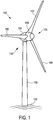
- a wind energy installation has, for example, an aerodynamic rotor with several rotor blades and is shown by way of example in FIG Fig. 1 shown.
- the aerodynamic properties of such rotor blades influence the performance of the rotor blades and thus the wind turbine.
- its profiles are optimized.
- the aerodynamic rotors In order to ensure the most constant possible electricity production, for example in regions with light wind, namely in particular at inland locations, the aerodynamic rotors have a rotor diameter that can be more than 80 meters. In the case of such large wind energy installations and thus also very large rotor blades, this leads to a high rotor blade weight.
- the large and heavy rotor blades generate high loads that act on the wind turbine during operation.
- a fundamentally different option for a rotor blade connection provides for a decreasing profile depth in the hub area in order to achieve an approximately circular profile cross-section for the hub connection starting from the shape of a standard profile in the central area of the rotor blade via an elliptical profile cross-section - this is for example in DE 102008052858 B9 described in which a blunt trailing edge of a rotor blade is provided.
- German Patent and Trademark Office researched the following prior art in the priority application for the present PCT application: DE 10 2014 108 917 A1 WO 2014/025 252 A1 , WO 2013/153 009 A1 , DE 10 2013 210 901 A1 , EP 2 568 166 A1 , DE 10 2014 206 345 A1 , DE 10 2008 052 858 B9 and DE 10 2013 101 232 A1 .
- the invention is based on the object of eliminating or reducing at least one of the above-mentioned problems, in particular of specifying a rotor blade which in any case still has limited good lift values in the hub area and at the same time reduces the problem of trailing edge turbulence.
- the rotor blade should have an optionally increasing profile thickness or decreasing profile thickness in the hub area, but in any case in the area of this profile thickness in the hub area it should be designed so that it can be transported comparatively more easily.
- the object relating to the rotor blade is achieved by a rotor blade of claim 1.
- the invention also leads to a wind energy installation according to claim 16.
- WO 2014/025 252 A1 is registered before the priority date of the present application and is only published afterwards and is therefore only relevant with regard to the novelty regarding the present application - WO 2014/025252 A1 shows an aerodynamic profile with a non-symmetrical, turned-in, tail-like throat body (swallow tail shaped) at a rear edge of the aerodynamic profile, which can be used for a wind turbine, for example.
- the non-symmetrical, turned-in, tail-like (dovetail-like) throat body has a first part and a second part, between which the throat (cavity) is formed.
- the first and second parts each have an upper and lower straight outer surface, which is correspondingly flush with an upper and lower side of the aerodynamic profile.
- the invention is based on the consideration that in the course of the constant further development of wind energy installations, the rotor diameter will increase in order to be able to extract even more energy from the wind. Due to the aerodynamic and structural-mechanical laws of nature, however, it is not, or only to a limited extent, possible to merely increase the length of the rotor blades and, for example, to maintain the width or profile depth, as this does not result in clean flow conditions in the area of application around the aerodynamic profile can. Due to the increasingly larger area of the rotors, the sound emission level of the entire wind energy installation also rises, which must also be taken into account.
- the invention has recognized that, in principle, the design of a rotor blade with an aerodynamic standard-type profile in the tip area and middle area results in a rotor blade with an aerodynamic thickness profile - in particular a flatback profile blunt rear edge, especially in the hub area - is advantageous. This enables a reduction in blade depth while maintaining the same buoyancy behavior.
- the invention has recognized that it is basically still advantageous - that is, in accordance with the applicant's concept with a further increasing profile thickness (but not necessarily) as in WO 2013/153009 A1 -
- the rotor blade is designed as a thickness profile which has a mandrel widening on its rear edge.
- the rear edge is to be understood as the flat rear edge and the thorn extension is considered in relation to this.
- An actual, in this respect pointed, rear edge is then formed at the end of the mandrel widening.
- the profile depth in the hub area be advantageously designed to be small, but also vortex shedding and thus the sound emission can advantageously be designed.
- the rotor blade at least partially has a thickness profile and the thickness profile has a first mandrel extension on the rear edge on the suction side and a second mandrel extension on the rear edge on the pressure side.
- the thickness profile is advantageously designed as a flatback profile, that is to say designed with a blunt rear edge.
- the rear edge is advantageously a flat rear edge which has a relative thickness, in particular a relative thickness of more than 5%.
- the thickness profile advantageously has a relative thickness of more than 40%, in particular more than 45%.
- a relative mandrel depth, measured from the rear edge, is advantageously below 25% and / or at least above a relative thickness of the rear edge, in particular above 5%.
- the flat rear edge is to be understood, and in relation to this, the relative thickness and the thorn expansion are considered.
- Such a profile also referred to as a rose thorn profile, corresponds to a modification according to the aforementioned development of a flatback profile and in this case corresponds to an advantageous development of the invention.
- the thickness profile advantageously has a relative thickness of more than 50%, in particular more than 75%.
- the sound emission is reduced in comparison to the flatback profile due to the preferably double - that is, on the suction and pressure side - thinly tapering end edge piece of a mandrel extension.
- the special shape of the trailing edge spikes enables controlled trailing edge vortex formation to be achieved. It has been shown that a vortex can be stabilized in the groove between the suction-side and the pressure-side mandrel (in any case, however, below or above a mandrel), especially with double thorns attached to the suction and pressure side, and nevertheless the profile in the area of the Hub area has comparatively good lift values. It has been shown to be advantageous that stable, even if pulsating or oscillating, formation of a vortex in the throat or below or above a mandrel is possible, even with more turbulent flow or different winds. A stable, albeit pulsating or oscillating formation of a vortex in the throat or below or above a mandrel increases the effective profile depth and thus improves the lift behavior of the profile.
- a relative mandrel depth measured at the rear edge is advantageously below 25% and / or at least above a relative thickness of the rear edge, in particular above 5%, with a maximum relative mandrel depth advantageously being between 15 and 25%.
- the flat rear edge is to be understood, and in relation to this, the relative thickness and the relative mandrel depth of the mandrel extension are considered.
- the rear edge is at least partially provided with a serration shape, that is, embodied as a serrated rear edge, so to speak.
- a serrated rear edge can be implemented on the suction side and / or on the pressure side, or or only on the pressure and / or suction side or also over the entire flat course of the rear edge.
- the flat rear edge but also possibly a pointed rear edge of the mandrel extension is to be understood and in relation to this the serrated rear edge becomes considered; ie in particular a serration form is attached to the end of the thorn extension.
- a flow stabilizer in the area of the hub area on the suction and / or pressure side.
- a flow stabilizer can be selected from the group consisting of spoilers, boundary layer fences, boundary layer suction.
- a further development according to the invention has also proven to be advantageous in which the thickness profile at least partially has a vortex generator in the area of the hub area on the suction and / or pressure side.
- a vortex generator is selected from the group consisting of: fin, knob, dimple, web or similar turbulators, a blow-out or suction structure.
- Vortex generators or similar turbulators are generally small artificially applied surface disturbances. They generate eddies and convert a laminar boundary layer flow into a turbulent one. The flow separation is delayed.
- Turbulators include, for example, transverse rails, small vertical plates or bores. Another possibility of turning the boundary layer flow is with the blow-out or suction turbulator. This is a series of fine bores through which air is blown into the boundary layer perpendicular to the direction of flow or is extracted.
- a particularly preferred development provides that in a first area, namely in the hub area in a first area close to the hub, the thickness profile has the mandrel extension on its rear edge and in a second area, namely in the hub area, in a second area remote from the hub , the thickness profile the trailing edge is a flat trailing edge without the mandrel extension.
- the concept of a local maximum between the root and the tip of the rotor blade can be implemented particularly advantageously in combination with the mandrel extension according to the invention. It is preferably provided that in the hub area between the first area, in particular the area close to the hub in the hub area, and the second Area, in particular the area remote from the hub in the hub area, the thickness profile has a maximum profile depth.
- a relative profile thickness which is defined as the ratio of profile thickness to profile depth, has a local maximum in a region, preferably a central region, between the rotor blade root of the hub region and the rotor blade tip of the tip region.
- the relative profile thickness of the local maximum can preferably be 35% to 50% and / or the rotor blade can have a profile depth of 1500 mm to 3500 mm in the region of the local maximum.
- the rotor blade is composed of a first and a second rotor blade section and the first rotor blade section has the rotor blade root and the second rotor blade section has the rotor blade tip, and the first and second rotor blade sections are connected to one another at a separation point.
- the separation point is preferably arranged in the middle area between the rotor blade root and the rotor blade tip and / or in the area of the local maximum.
- the rotor blade has an absolute profile depth of at least 3900 mm, in particular an absolute profile depth in a range of 4000 mm to 8000 mm, in a first area, in particular an area close to the hub in the hub area.
- the rotor blade starting from the rotor blade root, has an absolute profile depth of a maximum of 1000 mm, in particular an absolute profile depth in a range of 700 mm to 400 mm, in the range from 90% to 95% of the total length.
- the rotor blade has a profile depth in the central region (II) which corresponds to approximately 20% to 30%, in particular approximately 25%, of the profile depth in the hub region.
- the thickness profile advantageously has a relative thickness of more than 50%, in particular more than 75%.
- the thickness profile for the rotor blade is preferably formed in the form of an essentially elliptical, oval or cylindrical core. In particular in the case of an ideal or oval ellipse, the thickness profile advantageously has a relative thickness of more than 50%, in particular more than 75%.
- the core preferably develops into a cylindrical shape towards the hub connection, i.e. the rotor blade has a thickness profile with a relative thickness of up to 100%.
- the core is particularly advantageously formed as a wound part.
- the core is designed as a (e.g. glass or carbon) fiber-reinforced (GRP) profile.
- GRP fiber-reinforced
- filaments or mats or similar fibers are wound onto a mandrel which is later removed so that the core remains as a wound part, in particular a GRP wound part.
- the rotor blade can be manufactured particularly efficiently in the hub area by attaching the mandrel extension to the core as the aforementioned thickness profile with a relative thickness of more than 50%, in particular more than 75%, on its rear edge with a relative rear edge thickness, in particular only the mandrel extension becomes.
- a substantially cylindrical or oval winding part with a thickness profile of a advantageous relative thickness of more than 50%, in particular more than 75% and a mandrel extension is in this sense as a particularly preferred embodiment in Fig. 12 shown.
- the cylindrical or oval core preferably the essentially cylindrical or oval winding part, has the first mandrel extension on the rear edge on the suction side and the second mandrel extension on the rear edge on the pressure side, forming a groove with a flat bottom between the first and second mandrel extension.
- a relative and / or absolute profile thickness which is defined as the ratio of profile thickness to profile depth, should decrease from a rotor blade root to a rotor blade tip.
- the flat base of a groove between the first and second mandrel extensions is preferably arched outwards, at least in the region of the hub region close to the hub.
- the flat base of a groove between the first and second mandrel extensions is preferably curved inward, at least in the region of the hub region remote from the hub.
- the first and second mandrel extensions are particularly preferably arranged on the rear edge at a circumferential angle below 60 °, the circumferential angle being measured starting from a profile axis, that is, without an angle of attack, starting from a horizontal.
- the first mandrel extension on the rear edge has a relative mandrel depth that is less than a relative mandrel depth of the second mandrel extension on the rear edge on the pressure side.
- the second mandrel extension on the rear edge has an orientation that is more inclined towards the pressure side than an alignment of the first mandrel extension on the rear edge on the suction side .
- the first mandrel extension on the rear edge runs at a largely fixed circumferential angle in the direction of the tip area and on the pressure side the second mandrel extension on the rear edge runs with a largely decreasing circumferential angle in the direction of the tip area .
- a mandrel widening on the suction side with a largely fixed circumferential angle a largely fixed position between a 1 o'clock and 3 o'clock position, for example at a 2 o'clock position, and a mandrel extension on the pressure side is arranged, for example, in a position between a 5 o'clock and 3 o'clock position; preferably with a steadily decreasing position from a 5 o'clock to a 3 o'clock position running in the direction of the tip area.
- the first mandrel extension preferably converge in the hub area at the rear edge and the second mandrel extension at the rear edge, in particular at a position of a circumferential angle of 0 ° or at a negative circumferential angle.
- the suction-side mandrel extension and the pressure-side mandrel extension converge to form a pointed rear edge; preferably at a starting angle of 0 °; i.e. (without angle of attack / twist) at a 3 o'clock position.
- the second mandrel extension at the rear edge has a pressure-side underside curved towards the pressure-side, in particular a pressure-side underside curved towards the pressure-side with increasing curvature - so to speak with a negative curvature.
- the second mandrel extension on the rear edge has a lip curved towards the pressure side, in particular a spoiler lip or Guerney flap, in particular with an aerodynamic transition to a curve on the pressure side curved towards the pressure side Bottom.
- a rotor blade can preferably be implemented which has flow velocities of a standardized flow in the area of a throat between the first and second mandrel widening, which are between 0.01 Ma and a maximum of 0.1 Ma, in particular between 0.02 Ma and a maximum of 0.06 Ma.
- a rotor blade can preferably be implemented which has a glide ratio (lift / drag ratio) which, at angles of attack (twist) of up to 5 °, are above 1 and below 10, in particular
- a glide ratio (lift / drag ratio) increases and / or an angle of attack (twist) of a profile of the rotor blade decreases from an area of the hub area (I) close to the hub to an area of the hub area remote from the hub.
- Fig. 1 shows a wind energy installation 100 with a tower 102 which is erected on a foundation 103.
- a nacelle 104 machine house
- a rotor 105 which has a rotor hub 106 and rotor blades 107, 108 and 109 attached to it.
- the rotor 105 is coupled to an electrical generator inside the nacelle 104 for converting mechanical work into electrical energy.
- the gondola 104 is rotatably mounted on the tower 102, the foundation 103 of which provides the necessary stability.
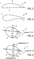
- tip area III shows Fig. 2 a rotor blade profile 30 essentially according to a standard profile, the suction side S being essentially convex and the pressure side D being essentially concave or straight.
- Fig. 3 shows a rotor blade profile 20 of a rotor blade 1 in the hub area with a blunt trailing edge F, the trailing edge having a relative trailing edge thickness Fd which can be in the range of 5% or more.
- the profiles 30, 20 of the Fig. 2, Fig. 3 can also be present in the middle area or hub area.
- Fig. 4 shows a rose mandrel profile of a rotor blade profile 10 for a rotor blade 1 of the preferred embodiment.
- the rotor blade profile in the hub region I has a thickness profile with a relative thickness of more than 45% and a trailing edge of more than 5% on the suction and pressure sides S, D, respectively a rose thorn in the form of a thorn extension R1, R2.
- the mandrel depth measured from the rear edge F is below 25% and above a relative thickness of the rear edge, namely particularly above 5%.
- the rotor blade profile is already shown with an angle of attack (twisted), which in any case in the area of the hub area close to the hub can be between 0 ° and 70 °, in particular between 0 ° and 45 °, and tends to increase in the process.
- Fig. 5 shows the rotor blade profile of the Fig. 4 with additional vortex generators W1, W2, the vortex generators being arranged on the suction and pressure side S, D.
- Fig. 6 shows a distribution of different profile geometries of a rotor blade 1 of an embodiment.
- profile thicknesses 2 and profile depths 3 are shown in sections.
- the rotor blade 1 has the rotor blade root 4 at one end and a connection area 5 for attaching a rotor blade tip at the end facing away from it.
- the rotor blade has a large profile depth 3.
- the profile depth 3 is very much smaller.
- the profile depth decreases significantly up to a central region II.
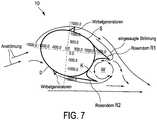
- Fig. 7 shows that in the throat K of the leaf profile between the suction-side and pressure-side rose thorns, that is, in the throat K between the suction-side and pressure-side thorn enlargements R1, R2, a comparatively stable throat vortex W is formed in the direction of the suction side.
- the anticlockwise throat vortex sucks in air from the suction side S into the throat K between the suction-side and pressure-side mandrels R1, R2 and prevents the flow from separating on the suction side.
- the pressure side flow on pressure side D additionally stabilizes the throat vortex W.
- the blade profile in the hub area I has a profile depth that is lengthened by the throat vortex, so that a longer flow line is formed, if you will, the profile depth of the blade profile extended by the stable throat vertebra.
- the rotor blade profile is the Fig. 7 provided with vortex generators, so that a detachment of an oncoming flow in the interface does not occur prematurely. This leads to stable pressure conditions for the throat vertebra in the throat between the suction-side and pressure-side rose thorns of the thorn widening of the leaf profile.
- Fig. 7 shows a flow around the rotor blade with currents at an angle of attack of 7 ° - however, the concept of the invention is in no way limited to such a small angle of attack but rather aims at the less favorable case of an angle of attack of 30 °.
- Fig. 7 shows Fig. 7 the basic principle and the possibility of significantly saving material by using rose thorns.
- the vortex generators can also be smaller than shown; the rose thorns are therefore relatively smaller.
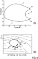
- Fig. 8 shows in (A) a coordinate representation of the rose thorn profile of Fig. 7 with an associated flow course (B); in particular, the formation of the in Fig. 7 designated sucked-in flow can be seen as a stabilized vortex W between the spikes R1, R2.
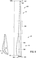
- Fig. 9 shows a side view of a rotor blade 900 of an embodiment over its total length I, ie from 0% to 100%.
- the rotor blade 900 has a rotor blade root 904 at one end and a rotor blade tip 907 at the end facing away from it.
- the rotor blade tip 907 is connected to the remaining part of the rotor blade at a connection area 905.
- the rotor blade root 904 the rotor blade has a large profile depth.
- the profile depth is very much smaller in the connection area 905 and at the rotor blade tip 907.
- the profile depth decreases significantly up to a central region 906.
- a separation point can be provided in the middle area 906 (here not shown). From the middle area 906 to the connection area 905, the profile depth is almost constant.
- the rotor blade 900 has a two-part shape in the area of the rotor blade root 904.
- the rotor blade 900 thus consists of a basic profile 909, on which a further section 908 for increasing the rotor blade depth of the rotor blade 900 is arranged in the area of the rotor blade root 904.
- the section 908 is glued to the basic profile 909, for example.
- Such a two-part form is easier to handle during transport to the installation site and easier to manufacture.
- a hub connection area 910 can be seen.
- the rotor blade 900 is connected to the rotor hub via the hub connection area 910.
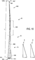
- FIG. 9 shows a further side view of the rotor blade 900 of FIG Fig. 9 .
- the rotor blade 900 with the basic profile 909, the section 908 for increasing the rotor blade depth, the middle area 906, the rotor blade root 904 and the hub connection area 910 as well as the connection area 905 to the rotor blade tip 907 can be seen.
- the rotor blade tip 907 is designed as a so-called winglet. This reduces eddies at the tip of the rotor blade.
- section 908 is shown as a trailing edge piece with the groove K between the suction-side and pressure-side rose mandrels R1, R2.
- the depth of the trailing edge piece turns out to be smaller, since the effective relative profile thickness of the blade profile in the hub area is increased as a result of the preferred stable formation of the throat vertebrae.
- Fig. 10 the trailing edge piece is shown once in view A without serration form and once in view B with serration form.
- a serration form or other flow-stabilizing measures can support the development of the throat vertebrae and thus increase the effective relative profile thickness of the blade profile in the hub area.
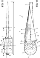
- the Fig.11 shows a preferred embodiment - recognizable in the upper part - as a first modification with a rear edge piece - for example in the form of a rear edge box, which is attached separately - as this is already shown as section 908 in Fig. 9 and Fig. 10 is shown.
- the rotor blade 1 shown with a correspondingly increased profile depth in the hub region I was particularly shown in connection with FIG Fig. 9 and Fig. 10 described - with the Trailing edge piece with a thorn extension, ie as section 908, the depth of the trailing edge piece is less than that of a trailing edge piece without a thorn extension, given similar lift and glide values.
- the profile depth of such a rotor blade 1 can therefore be comparatively reduced due to the aforementioned stable throat vortex formation, so that an effective relative profile thickness of the blade profile in the hub area can be increased. Since the effective relative profile thickness of the blade profile in the hub area increases as a result of the preferred stable throat vortex formation, this is preferably, but not necessarily, suitable for implementing a rotor blade 1 as shown in FIG Fig. 6 is shown.
- Fig.11 also shows a further particularly preferred embodiment as a second modification, which is referred to here as rotor blade 1 '.
- the mandrel extension in the hub area is formed “directly” on a rear edge F of the core of the rotor blade, the mandrel extension R1, R2 remaining below the dashed line L '; the dashed line L 'thus forms the rear edge of the mandrel extension R1, R2.
- the trailing edge piece 908 of the rotor blade 1 is omitted in the case of the rotor blade 1 '.
- the profile depth of the rotor blade 1 ' is limited to an area below the dashed line L'.
- the rotor blade 1 ' is designed with a significantly smaller profile depth (chord length) with, as is shown, nevertheless considerable and advantageous lift and glide values. This leads to a very considerable reduction and thus considerably improved transportability of the rotor blade 1 '.
- the rotor blade 1 ' can be manufactured particularly efficiently in the hub area I by attaching to the core as the aforementioned thickness profile with a relative thickness of more than 50%, in particular more than 75% - i.e. at the rear edge of the core with a relatively comparatively high rear edge thickness- - the mandrel extension is attached, in particular (as here in this in Fig.12 embodiment shown) only the mandrel extension is attached.
- a separation point R is provided, at which the rotor blade 1, 1' is assembled in the longitudinal direction.
- Fig.12 shows a three-dimensional representation of a preferred embodiment of a rotor blade in the hub area (I) with a recognizable mandrel widening in the hub area, the thickness profile having the mandrel widening at its rear edge in a first area close to the hub and also in a second area, namely in the hub area in a second area remote from the hub, the thickness profile, the rear edge, a flat rear edge, the mandrel extension.
- the rotor blade 1 ' is for its hub area I with a bead-like widened separation point R in Fig.12 shown in perspective.
- the perspective illustration of the rotor blade 1 'in Fig.12 shows that the thickness profile in the hub region I is formed in the form of an essentially elliptical and then developing in the longitudinal direction towards the hub, oval and then cylindrical core 11 ', which is designed as a winding part WT, which is shown in FIG Fig. 13 is marked accordingly.
- a first mandrel extension R1 is attached to the suction side S of the core 11 'and a second mandrel extension R2 is attached to the pressure side D of the core 11', namely to its rear edge F.
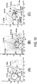
- Fig. 13 shows related to Fig.12 and Fig.11 for the in Fig.11 Cross-sections A - A and B - B and C - C shown in views (A).
- (B) and (C) the Fig. 13 the corresponding profiles with a relative thickness of more than 50% and then more than 75% and finally practically 100% of the rotor blade 1 'towards the hub - a calculated distribution of flow velocities is shown for this.
- the flow velocities are shown as shading and show the throat vortex W in the throat K between the mandrels R1, R2 on the winding part WT - reference will be made to this later.
- a relative and / or absolute profile thickness 2 which is defined as the ratio of profile thickness 2 to profile depth 3 (see Fig. 6 )
- a relative profile thickness increases from a rotor blade tip 5, 7 to a rotor blade root 4; namely, a relative profile thickness increases from initially less than 45% to more than 50%, then increases to more than 75% up to a relative profile thickness of practically 100% of a cylindrical blade connection on the rotor blade root 4 or hub.
- first and second mandrel extension R1, R2 are arranged on the rear edge F at a circumferential angle below 60 °, namely here at one in the Fig.12 Drawn circumferential angle ⁇ 1, ⁇ 2 of about 45 ° are arranged.
- the circumferential angle ⁇ 1, ⁇ 2 of the mandrel extensions R1, R2 is measured here on the basis of a profile axis (profile chord A of the profile of the rotor blade 1 ').
- the circumferential angle a1 on the suction side S of the first mandrel extension R1 on the rear edge F now runs at a largely fixed circumferential angle a1 in the direction of the tip area.
- the circumferential angle a2 decreases, as in Fig.12 recognizable, for the second mandrel extension R2 at the rear edge F in the direction of the tip area III.
- the mandrel extensions R1, R2 converge in order to converge at the intersection point T at the end of the hub region I. This corresponds roughly to a position at which the circumferential angle for both rose thorn profiles R1, R2 is approximately 0 ° or above, possibly at a fixed circumferential angle ⁇ 1.
- the thickness profile in the hub area I in a first area, namely an area I.1 near the hub in the hub area I, the thickness profile has a comparatively high first relative thickness and the mandrel widening at its flat rear edge.
- the rear edge of the thickness profile in the hub area I in a second area, in particular an area I.2 remote from the hub, in the hub area I, the rear edge of the thickness profile has a pointed rear edge without a mandrel extension or a flat rear edge of a second smaller relative thickness also with the mandrel extension.
- the mandrel extension R2 on the pressure side follows the twist of the rotor blade 1 ', so to speak; ie with the decreasing angle of attack ⁇ in the direction of the tip area III - this was already over Fig. 6 recognizable and is in Fig.12 clearly recognizable again.
- the profile of the rotor blade already has a pointed rear edge which is formed from the converging first and second spikes R1, R2 of the suction and pressure side.
- the rotor blade 1 ' has a blunt trailing edge ( Fig.
- the first mandrel extension R1 on the rear edge F has a relative mandrel depth which is less than a relative mandrel depth of the second mandrel extension R2 on the rear edge F on the pressure side D. of the rotor blade 1 '. Furthermore, it is off Fig.12 It can be seen that in the area of the hub area I close to the hub on the pressure side, the second mandrel extension R2 on the rear edge has an orientation that is more inclined towards the pressure side than an alignment of the first mandrel extension R1 on the rear edge on the suction side S. This can be seen in that the orientation angle ⁇ 1 for the first mandrel extension R1 is greater than the orientation angle ⁇ 2 for the second mandrel extension R2.
- a curve of a pressure-side lower side R2u of the mandrel extension R2 is provided that is curved towards the pressure side D. That is to say, for the lower side U of the second mandrel extension R2 on the pressure side, a curve curved toward the pressure side D with increasing curvature is provided.
- the buoyancy effect that can be achieved in this way can also be reinforced by a so-called arched lip; for example, a spoiler lip or a Guerney flap or the like, as it is in Fig. 13 View (C) can be seen. This leads to an increase in the pressure on the pressure side D and thus increased lift values.
- a glide ratio (lift / drag ratio) - as shown for views (A), (B) and (C) in Fig. 13 and Fig. 14 is shown (i.e. for the cross-sections A - A, B - B and C - C of the Fig.11 ) is still comparatively high, namely at angles of incidence ⁇ of up to 5 ° for section A - A actual, this is still at values of at least up to 2.5, for section B - B still at values of up to 8, and for the section C - C still with values of up to even 10.
Landscapes
- Engineering & Computer Science (AREA)
- Physics & Mathematics (AREA)
- Fluid Mechanics (AREA)
- Life Sciences & Earth Sciences (AREA)
- Sustainable Development (AREA)
- Sustainable Energy (AREA)
- Chemical & Material Sciences (AREA)
- Combustion & Propulsion (AREA)
- Mechanical Engineering (AREA)
- General Engineering & Computer Science (AREA)
- Wind Motors (AREA)
Applications Claiming Priority (2)
| Application Number | Priority Date | Filing Date | Title |
|---|---|---|---|
| DE102016201114.6A DE102016201114A1 (de) | 2016-01-26 | 2016-01-26 | Rotorblatt einer Windenergieanlage und Windenergieanlage |
| PCT/EP2017/051673 WO2017129691A1 (de) | 2016-01-26 | 2017-01-26 | Rotorblatt einer windenergieanlage und windenergieanlage |
Publications (2)
| Publication Number | Publication Date |
|---|---|
| EP3408533A1 EP3408533A1 (de) | 2018-12-05 |
| EP3408533B1 true EP3408533B1 (de) | 2021-03-17 |
Family
ID=57956267
Family Applications (1)
| Application Number | Title | Priority Date | Filing Date |
|---|---|---|---|
| EP17702578.0A Active EP3408533B1 (de) | 2016-01-26 | 2017-01-26 | Rotorblatt einer windenergieanlage und windenergieanlage |
Country Status (9)
| Country | Link |
|---|---|
| US (1) | US10968885B2 (da) |
| EP (1) | EP3408533B1 (da) |
| JP (1) | JP6691616B2 (da) |
| CN (1) | CN108603486B (da) |
| BR (1) | BR112018015058A2 (da) |
| CA (1) | CA3010688C (da) |
| DE (1) | DE102016201114A1 (da) |
| DK (1) | DK3408533T3 (da) |
| WO (1) | WO2017129691A1 (da) |
Families Citing this family (11)
| Publication number | Priority date | Publication date | Assignee | Title |
|---|---|---|---|---|
| DK3431753T3 (da) * | 2016-02-12 | 2020-07-13 | Lm Wp Patent Holding As | Savtakket bagkantspanel til en vindmøllevinge |
| DE102016117012A1 (de) * | 2016-09-09 | 2018-03-15 | Wobben Properties Gmbh | Windenergieanlagen-Rotorblatt |
| DE102017124861A1 (de) | 2017-10-24 | 2019-04-25 | Wobben Properties Gmbh | Rotorblatt einer Windenergieanlage und Verfahren zu dessen Auslegung |
| DE102018103732A1 (de) * | 2018-02-20 | 2019-08-22 | Wobben Properties Gmbh | Rotorblatt für eine Windenergieanlage und Verfahren |
| DE102018121249A1 (de) | 2018-08-30 | 2020-03-05 | Wobben Properties Gmbh | Rotorblatt für eine Windenergieanlage und Windenergieanlage |
| DE102019113080A1 (de) * | 2019-05-17 | 2020-11-19 | Wobben Properties Gmbh | Rotorblatt und Windenergieanlage |
| DE102019117365A1 (de) * | 2019-06-27 | 2020-12-31 | Wobben Properties Gmbh | Rotor für eine Windenergieanlage, Windenergieanlage und zugehöriges Verfahren |
| DE102019119027B4 (de) * | 2019-07-12 | 2022-04-28 | Wobben Properties Gmbh | Rotorblatt und Windenergieanlage |
| EP3954892A3 (de) * | 2020-07-21 | 2022-04-20 | Wobben Properties GmbH | Rotorblatt für eine windenergieanlage, rotor für eine windenergieanlage, bauwerk und windenergieanlage |
| CN117280113A (zh) * | 2021-03-10 | 2023-12-22 | 维斯塔斯风力系统有限公司 | 风力涡轮机叶片 |
| CN114278494B (zh) * | 2021-11-25 | 2025-02-11 | 华北电力大学(保定) | 一种仿鲸鱼尾鳍的增升降噪风力机叶片结构 |
Family Cites Families (29)
| Publication number | Priority date | Publication date | Assignee | Title |
|---|---|---|---|---|
| US2562227A (en) * | 1947-07-09 | 1951-07-31 | Zobel Theodor Wilhelm | Flow profile for reduced drag |
| US5088665A (en) * | 1989-10-31 | 1992-02-18 | The United States Of America As Represented By The Administrator Of The National Aeronautics And Space Administration | Serrated trailing edges for improving lift and drag characteristics of lifting surfaces |
| US5531406A (en) * | 1994-05-16 | 1996-07-02 | University Of Southern California | Flow-vectored trailing-edge for airfoils and jets |
| JP2003336572A (ja) | 2002-02-22 | 2003-11-28 | Mitsubishi Heavy Ind Ltd | ナセル構造の風車 |
| JPWO2005116446A1 (ja) * | 2004-05-27 | 2008-04-03 | 株式会社アイ・ピー・ビー | 垂直軸風車用ブレードおよび垂直軸風車 |
| US8419363B2 (en) | 2006-07-07 | 2013-04-16 | Danmarks Tekniske Universitet | Variable trailing edge section geometry for wind turbine blade |
| CA2703587A1 (en) | 2008-01-30 | 2009-08-06 | James G.P. Dehlsen | Retractable blade structure with a split trailing edge |
| DE102008052858B9 (de) | 2008-10-23 | 2014-06-12 | Senvion Se | Profil eines Rotorblatts und Rotorblatt einer Windenergieanlage |
| US9039381B2 (en) | 2010-12-17 | 2015-05-26 | Vestas Wind Systems A/S | Wind turbine blade and method for manufacturing a wind turbine blade with vortex generators |
| CN103782027B (zh) * | 2011-05-16 | 2017-03-22 | Lm Wp 专利控股有限公司 | 具有噪音降低装置的风力涡轮机叶片及相关方法 |
| US8414261B2 (en) | 2011-05-31 | 2013-04-09 | General Electric Company | Noise reducer for rotor blade in wind turbine |
| EP2568166B1 (de) * | 2011-09-09 | 2015-07-15 | Nordex Energy GmbH | Windenergieanlagenrotorblatt mit einer dicken Profilhinterkante |
| WO2013054404A1 (ja) * | 2011-10-12 | 2013-04-18 | 三菱重工業株式会社 | 風車翼及びこれを備えた風力発電装置ならびに風車翼の設計方法 |
| US8376703B2 (en) * | 2011-11-21 | 2013-02-19 | General Electric Company | Blade extension for rotor blade in wind turbine |
| US9617974B2 (en) | 2011-11-23 | 2017-04-11 | Lm Wp Patent Holding A/S | Wind turbine blade |
| US9677538B2 (en) * | 2012-02-09 | 2017-06-13 | General Electric Company | Wind turbine rotor blade assembly with root extension panel and method of assembly |
| CN104271330A (zh) | 2012-04-02 | 2015-01-07 | 绿色材料有限责任公司 | 用天然材料制造的注射模制物件和其制造方法 |
| DE102012206109C5 (de) | 2012-04-13 | 2022-06-09 | Wobben Properties Gmbh | Rotorblatt einer Windenergieanlage |
| US11136958B2 (en) * | 2012-08-06 | 2021-10-05 | Nederlandse Organisatie Voor Toegepast-Natuurwetenschappelijk Onderzoek Tno | Swallow tail airfoil |
| NL2009286C2 (en) * | 2012-08-06 | 2014-02-10 | Stichting Energie | Swallow tail airfoil. |
| US9377005B2 (en) * | 2013-03-15 | 2016-06-28 | General Electric Company | Airfoil modifiers for wind turbine rotor blades |
| DE102013210901A1 (de) | 2013-06-11 | 2014-12-11 | Wobben Properties Gmbh | Rotorblatt einer Windenergieanlage und Windenergieanlage |
| US20150003985A1 (en) | 2013-06-27 | 2015-01-01 | General Electric Company | Moveable surface features for wind turbine rotor blades |
| DE102014203442A1 (de) * | 2013-11-04 | 2015-05-07 | Senvion Se | Rotorblatt einer Windenergieanlage und Windenergieanlage |
| DE102014206345A1 (de) | 2014-04-02 | 2015-10-08 | Wobben Properties Gmbh | Verfahren zum Anbringen einer Zackenhinterkante an einer Blatthinterkante eines Rotorblattes |
| DE102014215966A1 (de) * | 2014-08-12 | 2016-02-18 | Senvion Gmbh | Rotorblattverlängerungskörper sowie Windenergieanlage |
| CN104595110A (zh) | 2014-12-01 | 2015-05-06 | 东方电气集团东方汽轮机有限公司 | 一种风机风轮调整装置及包含该装置的风机组 |
| US10180125B2 (en) * | 2015-04-20 | 2019-01-15 | General Electric Company | Airflow configuration for a wind turbine rotor blade |
| US20190024631A1 (en) * | 2017-07-20 | 2019-01-24 | General Electric Company | Airflow configuration for a wind turbine rotor blade |
-
2016
- 2016-01-26 DE DE102016201114.6A patent/DE102016201114A1/de not_active Withdrawn
-
2017
- 2017-01-26 US US16/072,823 patent/US10968885B2/en active Active
- 2017-01-26 BR BR112018015058-4A patent/BR112018015058A2/pt not_active Application Discontinuation
- 2017-01-26 EP EP17702578.0A patent/EP3408533B1/de active Active
- 2017-01-26 DK DK17702578.0T patent/DK3408533T3/da active
- 2017-01-26 CA CA3010688A patent/CA3010688C/en not_active Expired - Fee Related
- 2017-01-26 WO PCT/EP2017/051673 patent/WO2017129691A1/de not_active Ceased
- 2017-01-26 CN CN201780008228.7A patent/CN108603486B/zh not_active Expired - Fee Related
- 2017-01-26 JP JP2018557210A patent/JP6691616B2/ja active Active
Non-Patent Citations (1)
| Title |
|---|
| None * |
Also Published As
| Publication number | Publication date |
|---|---|
| US10968885B2 (en) | 2021-04-06 |
| BR112018015058A2 (pt) | 2018-12-18 |
| US20190032631A1 (en) | 2019-01-31 |
| CA3010688C (en) | 2020-06-30 |
| EP3408533A1 (de) | 2018-12-05 |
| JP2019502870A (ja) | 2019-01-31 |
| CN108603486B (zh) | 2020-12-22 |
| CN108603486A (zh) | 2018-09-28 |
| CA3010688A1 (en) | 2017-08-03 |
| WO2017129691A1 (de) | 2017-08-03 |
| DE102016201114A1 (de) | 2017-07-27 |
| JP6691616B2 (ja) | 2020-04-28 |
| DK3408533T3 (da) | 2021-04-19 |
Similar Documents
| Publication | Publication Date | Title |
|---|---|---|
| EP3408533B1 (de) | Rotorblatt einer windenergieanlage und windenergieanlage | |
| EP1514023B1 (de) | Windenergieanlage | |
| DE102012206109B3 (de) | Rotorblatt einer Windenergieanlage | |
| EP3169897B1 (de) | Windenergieanlagen-rotorblatt, rotorblatthinterkante, und verfahren zum herstellen eines windenergieanlagen-rotorblattes, und windenergieanlage | |
| EP2280163B1 (de) | Windenergieanlage sowie Rotorblatt für eine Windenergieanlage | |
| DE102013207640B4 (de) | Windenergieanlagen-Rotorblatt | |
| EP3665384B1 (de) | Rotorblatt eines rotors einer windenergieanlage, windenergieanlage und verfahren zur verbesserung des wirkungsgrades eines rotors einer windenergieanlage | |
| EP3169898B1 (de) | Windenergieanlagen-rotorblatt, windenergieanlagen-rotorblattspitzenhinterkante, verfahren zum herstellen eines windenergieanlagen-rotorblattes und windenergieanlage | |
| DE19815519A1 (de) | Rotorblatt für eine Windkraftanlage | |
| DE102013206437A1 (de) | Rotorblatt einer Windenergieanlage und Windenergieanlage | |
| WO2015062710A1 (de) | Rotorblatt einer windenergieanlage und windenergieanlage | |
| EP2840255B1 (de) | Rotorflügelprofil fur eine Windturbine | |
| EP3824176B1 (de) | Rotorblatt für eine windenergieanlage und windenergieanlage | |
| DE102016117012A1 (de) | Windenergieanlagen-Rotorblatt | |
| EP3399183B1 (de) | Rotorblatt einer windenergieanlage | |
| EP3969743B1 (de) | Rotorblatt und verfahren zum auslegen eines rotorblatts einer windenergieanlage. | |
| EP3954892A2 (de) | Rotorblatt für eine windenergieanlage, rotor für eine windenergieanlage, bauwerk und windenergieanlage | |
| WO2016162350A1 (de) | Windenergieanlagen-rotorblatt | |
| WO2020043870A1 (de) | Rotorblatt für eine windenergieanlage und windenergieanlage | |
| WO2019162114A1 (de) | Rotorblatt für eine windenergieanlage und verfahren | |
| EP4671529A1 (de) | Rotorblatt umfassend elastikelement, verfahren und windenergieanlage |
Legal Events
| Date | Code | Title | Description |
|---|---|---|---|
| STAA | Information on the status of an ep patent application or granted ep patent |
Free format text: STATUS: UNKNOWN |
|
| STAA | Information on the status of an ep patent application or granted ep patent |
Free format text: STATUS: THE INTERNATIONAL PUBLICATION HAS BEEN MADE |
|
| PUAI | Public reference made under article 153(3) epc to a published international application that has entered the european phase |
Free format text: ORIGINAL CODE: 0009012 |
|
| STAA | Information on the status of an ep patent application or granted ep patent |
Free format text: STATUS: REQUEST FOR EXAMINATION WAS MADE |
|
| 17P | Request for examination filed |
Effective date: 20180827 |
|
| AK | Designated contracting states |
Kind code of ref document: A1 Designated state(s): AL AT BE BG CH CY CZ DE DK EE ES FI FR GB GR HR HU IE IS IT LI LT LU LV MC MK MT NL NO PL PT RO RS SE SI SK SM TR |
|
| AX | Request for extension of the european patent |
Extension state: BA ME |
|
| DAV | Request for validation of the european patent (deleted) | ||
| DAX | Request for extension of the european patent (deleted) | ||
| GRAP | Despatch of communication of intention to grant a patent |
Free format text: ORIGINAL CODE: EPIDOSNIGR1 |
|
| STAA | Information on the status of an ep patent application or granted ep patent |
Free format text: STATUS: GRANT OF PATENT IS INTENDED |
|
| INTG | Intention to grant announced |
Effective date: 20201021 |
|
| GRAS | Grant fee paid |
Free format text: ORIGINAL CODE: EPIDOSNIGR3 |
|
| GRAA | (expected) grant |
Free format text: ORIGINAL CODE: 0009210 |
|
| STAA | Information on the status of an ep patent application or granted ep patent |
Free format text: STATUS: THE PATENT HAS BEEN GRANTED |
|
| AK | Designated contracting states |
Kind code of ref document: B1 Designated state(s): AL AT BE BG CH CY CZ DE DK EE ES FI FR GB GR HR HU IE IS IT LI LT LU LV MC MK MT NL NO PL PT RO RS SE SI SK SM TR |
|
| REG | Reference to a national code |
Ref country code: GB Ref legal event code: FG4D Free format text: NOT ENGLISH |
|
| REG | Reference to a national code |
Ref country code: CH Ref legal event code: EP |
|
| REG | Reference to a national code |
Ref country code: DE Ref legal event code: R096 Ref document number: 502017009735 Country of ref document: DE |
|
| REG | Reference to a national code |
Ref country code: NL Ref legal event code: FP Ref country code: IE Ref legal event code: FG4D Free format text: LANGUAGE OF EP DOCUMENT: GERMAN |
|
| REG | Reference to a national code |
Ref country code: AT Ref legal event code: REF Ref document number: 1372468 Country of ref document: AT Kind code of ref document: T Effective date: 20210415 |
|
| REG | Reference to a national code |
Ref country code: DK Ref legal event code: T3 Effective date: 20210413 |
|
| REG | Reference to a national code |
Ref country code: LT Ref legal event code: MG9D |
|
| PG25 | Lapsed in a contracting state [announced via postgrant information from national office to epo] |
Ref country code: BG Free format text: LAPSE BECAUSE OF FAILURE TO SUBMIT A TRANSLATION OF THE DESCRIPTION OR TO PAY THE FEE WITHIN THE PRESCRIBED TIME-LIMIT Effective date: 20210617 Ref country code: GR Free format text: LAPSE BECAUSE OF FAILURE TO SUBMIT A TRANSLATION OF THE DESCRIPTION OR TO PAY THE FEE WITHIN THE PRESCRIBED TIME-LIMIT Effective date: 20210618 Ref country code: FI Free format text: LAPSE BECAUSE OF FAILURE TO SUBMIT A TRANSLATION OF THE DESCRIPTION OR TO PAY THE FEE WITHIN THE PRESCRIBED TIME-LIMIT Effective date: 20210317 Ref country code: HR Free format text: LAPSE BECAUSE OF FAILURE TO SUBMIT A TRANSLATION OF THE DESCRIPTION OR TO PAY THE FEE WITHIN THE PRESCRIBED TIME-LIMIT Effective date: 20210317 Ref country code: NO Free format text: LAPSE BECAUSE OF FAILURE TO SUBMIT A TRANSLATION OF THE DESCRIPTION OR TO PAY THE FEE WITHIN THE PRESCRIBED TIME-LIMIT Effective date: 20210617 |
|
| PG25 | Lapsed in a contracting state [announced via postgrant information from national office to epo] |
Ref country code: LV Free format text: LAPSE BECAUSE OF FAILURE TO SUBMIT A TRANSLATION OF THE DESCRIPTION OR TO PAY THE FEE WITHIN THE PRESCRIBED TIME-LIMIT Effective date: 20210317 Ref country code: RS Free format text: LAPSE BECAUSE OF FAILURE TO SUBMIT A TRANSLATION OF THE DESCRIPTION OR TO PAY THE FEE WITHIN THE PRESCRIBED TIME-LIMIT Effective date: 20210317 Ref country code: SE Free format text: LAPSE BECAUSE OF FAILURE TO SUBMIT A TRANSLATION OF THE DESCRIPTION OR TO PAY THE FEE WITHIN THE PRESCRIBED TIME-LIMIT Effective date: 20210317 |
|
| PG25 | Lapsed in a contracting state [announced via postgrant information from national office to epo] |
Ref country code: LT Free format text: LAPSE BECAUSE OF FAILURE TO SUBMIT A TRANSLATION OF THE DESCRIPTION OR TO PAY THE FEE WITHIN THE PRESCRIBED TIME-LIMIT Effective date: 20210317 Ref country code: CZ Free format text: LAPSE BECAUSE OF FAILURE TO SUBMIT A TRANSLATION OF THE DESCRIPTION OR TO PAY THE FEE WITHIN THE PRESCRIBED TIME-LIMIT Effective date: 20210317 Ref country code: EE Free format text: LAPSE BECAUSE OF FAILURE TO SUBMIT A TRANSLATION OF THE DESCRIPTION OR TO PAY THE FEE WITHIN THE PRESCRIBED TIME-LIMIT Effective date: 20210317 Ref country code: SM Free format text: LAPSE BECAUSE OF FAILURE TO SUBMIT A TRANSLATION OF THE DESCRIPTION OR TO PAY THE FEE WITHIN THE PRESCRIBED TIME-LIMIT Effective date: 20210317 |
|
| PG25 | Lapsed in a contracting state [announced via postgrant information from national office to epo] |
Ref country code: IS Free format text: LAPSE BECAUSE OF FAILURE TO SUBMIT A TRANSLATION OF THE DESCRIPTION OR TO PAY THE FEE WITHIN THE PRESCRIBED TIME-LIMIT Effective date: 20210717 Ref country code: PT Free format text: LAPSE BECAUSE OF FAILURE TO SUBMIT A TRANSLATION OF THE DESCRIPTION OR TO PAY THE FEE WITHIN THE PRESCRIBED TIME-LIMIT Effective date: 20210719 Ref country code: PL Free format text: LAPSE BECAUSE OF FAILURE TO SUBMIT A TRANSLATION OF THE DESCRIPTION OR TO PAY THE FEE WITHIN THE PRESCRIBED TIME-LIMIT Effective date: 20210317 Ref country code: SK Free format text: LAPSE BECAUSE OF FAILURE TO SUBMIT A TRANSLATION OF THE DESCRIPTION OR TO PAY THE FEE WITHIN THE PRESCRIBED TIME-LIMIT Effective date: 20210317 Ref country code: RO Free format text: LAPSE BECAUSE OF FAILURE TO SUBMIT A TRANSLATION OF THE DESCRIPTION OR TO PAY THE FEE WITHIN THE PRESCRIBED TIME-LIMIT Effective date: 20210317 |
|
| REG | Reference to a national code |
Ref country code: DE Ref legal event code: R097 Ref document number: 502017009735 Country of ref document: DE |
|
| PLBE | No opposition filed within time limit |
Free format text: ORIGINAL CODE: 0009261 |
|
| STAA | Information on the status of an ep patent application or granted ep patent |
Free format text: STATUS: NO OPPOSITION FILED WITHIN TIME LIMIT |
|
| PG25 | Lapsed in a contracting state [announced via postgrant information from national office to epo] |
Ref country code: AL Free format text: LAPSE BECAUSE OF FAILURE TO SUBMIT A TRANSLATION OF THE DESCRIPTION OR TO PAY THE FEE WITHIN THE PRESCRIBED TIME-LIMIT Effective date: 20210317 Ref country code: ES Free format text: LAPSE BECAUSE OF FAILURE TO SUBMIT A TRANSLATION OF THE DESCRIPTION OR TO PAY THE FEE WITHIN THE PRESCRIBED TIME-LIMIT Effective date: 20210317 |
|
| 26N | No opposition filed |
Effective date: 20211220 |
|
| PG25 | Lapsed in a contracting state [announced via postgrant information from national office to epo] |
Ref country code: SI Free format text: LAPSE BECAUSE OF FAILURE TO SUBMIT A TRANSLATION OF THE DESCRIPTION OR TO PAY THE FEE WITHIN THE PRESCRIBED TIME-LIMIT Effective date: 20210317 |
|
| PG25 | Lapsed in a contracting state [announced via postgrant information from national office to epo] |
Ref country code: IT Free format text: LAPSE BECAUSE OF FAILURE TO SUBMIT A TRANSLATION OF THE DESCRIPTION OR TO PAY THE FEE WITHIN THE PRESCRIBED TIME-LIMIT Effective date: 20210317 |
|
| PG25 | Lapsed in a contracting state [announced via postgrant information from national office to epo] |
Ref country code: IS Free format text: LAPSE BECAUSE OF FAILURE TO SUBMIT A TRANSLATION OF THE DESCRIPTION OR TO PAY THE FEE WITHIN THE PRESCRIBED TIME-LIMIT Effective date: 20210717 |
|
| PG25 | Lapsed in a contracting state [announced via postgrant information from national office to epo] |
Ref country code: MC Free format text: LAPSE BECAUSE OF FAILURE TO SUBMIT A TRANSLATION OF THE DESCRIPTION OR TO PAY THE FEE WITHIN THE PRESCRIBED TIME-LIMIT Effective date: 20210317 |
|
| REG | Reference to a national code |
Ref country code: CH Ref legal event code: PL |
|
| REG | Reference to a national code |
Ref country code: BE Ref legal event code: MM Effective date: 20220131 |
|
| PG25 | Lapsed in a contracting state [announced via postgrant information from national office to epo] |
Ref country code: LU Free format text: LAPSE BECAUSE OF NON-PAYMENT OF DUE FEES Effective date: 20220126 |
|
| PG25 | Lapsed in a contracting state [announced via postgrant information from national office to epo] |
Ref country code: BE Free format text: LAPSE BECAUSE OF NON-PAYMENT OF DUE FEES Effective date: 20220131 |
|
| PG25 | Lapsed in a contracting state [announced via postgrant information from national office to epo] |
Ref country code: LI Free format text: LAPSE BECAUSE OF NON-PAYMENT OF DUE FEES Effective date: 20220131 Ref country code: CH Free format text: LAPSE BECAUSE OF NON-PAYMENT OF DUE FEES Effective date: 20220131 |
|
| PG25 | Lapsed in a contracting state [announced via postgrant information from national office to epo] |
Ref country code: IE Free format text: LAPSE BECAUSE OF NON-PAYMENT OF DUE FEES Effective date: 20220126 |
|
| REG | Reference to a national code |
Ref country code: AT Ref legal event code: MM01 Ref document number: 1372468 Country of ref document: AT Kind code of ref document: T Effective date: 20220126 |
|
| PG25 | Lapsed in a contracting state [announced via postgrant information from national office to epo] |
Ref country code: AT Free format text: LAPSE BECAUSE OF NON-PAYMENT OF DUE FEES Effective date: 20220126 |
|
| PG25 | Lapsed in a contracting state [announced via postgrant information from national office to epo] |
Ref country code: HU Free format text: LAPSE BECAUSE OF FAILURE TO SUBMIT A TRANSLATION OF THE DESCRIPTION OR TO PAY THE FEE WITHIN THE PRESCRIBED TIME-LIMIT; INVALID AB INITIO Effective date: 20170126 |
|
| PG25 | Lapsed in a contracting state [announced via postgrant information from national office to epo] |
Ref country code: MK Free format text: LAPSE BECAUSE OF FAILURE TO SUBMIT A TRANSLATION OF THE DESCRIPTION OR TO PAY THE FEE WITHIN THE PRESCRIBED TIME-LIMIT Effective date: 20210317 Ref country code: CY Free format text: LAPSE BECAUSE OF FAILURE TO SUBMIT A TRANSLATION OF THE DESCRIPTION OR TO PAY THE FEE WITHIN THE PRESCRIBED TIME-LIMIT Effective date: 20210317 |
|
| PG25 | Lapsed in a contracting state [announced via postgrant information from national office to epo] |
Ref country code: MT Free format text: LAPSE BECAUSE OF FAILURE TO SUBMIT A TRANSLATION OF THE DESCRIPTION OR TO PAY THE FEE WITHIN THE PRESCRIBED TIME-LIMIT Effective date: 20210317 |
|
| PGFP | Annual fee paid to national office [announced via postgrant information from national office to epo] |
Ref country code: NL Payment date: 20250122 Year of fee payment: 9 |
|
| PGFP | Annual fee paid to national office [announced via postgrant information from national office to epo] |
Ref country code: DE Payment date: 20250214 Year of fee payment: 9 |
|
| PGFP | Annual fee paid to national office [announced via postgrant information from national office to epo] |
Ref country code: DK Payment date: 20250122 Year of fee payment: 9 |
|
| PGFP | Annual fee paid to national office [announced via postgrant information from national office to epo] |
Ref country code: FR Payment date: 20250123 Year of fee payment: 9 |
|
| PGFP | Annual fee paid to national office [announced via postgrant information from national office to epo] |
Ref country code: GB Payment date: 20250123 Year of fee payment: 9 |
|
| PG25 | Lapsed in a contracting state [announced via postgrant information from national office to epo] |
Ref country code: TR Free format text: LAPSE BECAUSE OF FAILURE TO SUBMIT A TRANSLATION OF THE DESCRIPTION OR TO PAY THE FEE WITHIN THE PRESCRIBED TIME-LIMIT Effective date: 20210317 |
|
| REG | Reference to a national code |
Ref country code: DE Ref legal event code: R082 Ref document number: 502017009735 Country of ref document: DE Representative=s name: EISENFUEHR SPEISER PATENTANWAELTE RECHTSANWAEL, DE |