EP3408549B1 - Palier à roulement, éolienne et procédé de fonctionnement d'un palier à roulement - Google Patents
Palier à roulement, éolienne et procédé de fonctionnement d'un palier à roulement Download PDFInfo
- Publication number
- EP3408549B1 EP3408549B1 EP17701480.0A EP17701480A EP3408549B1 EP 3408549 B1 EP3408549 B1 EP 3408549B1 EP 17701480 A EP17701480 A EP 17701480A EP 3408549 B1 EP3408549 B1 EP 3408549B1
- Authority
- EP
- European Patent Office
- Prior art keywords
- rolling bearing
- conveying
- inner ring
- outer ring
- lubricant
- Prior art date
- Legal status (The legal status is an assumption and is not a legal conclusion. Google has not performed a legal analysis and makes no representation as to the accuracy of the status listed.)
- Active
Links
Images


Classifications
-
- F—MECHANICAL ENGINEERING; LIGHTING; HEATING; WEAPONS; BLASTING
- F16—ENGINEERING ELEMENTS AND UNITS; GENERAL MEASURES FOR PRODUCING AND MAINTAINING EFFECTIVE FUNCTIONING OF MACHINES OR INSTALLATIONS; THERMAL INSULATION IN GENERAL
- F16C—SHAFTS; FLEXIBLE SHAFTS; ELEMENTS OR CRANKSHAFT MECHANISMS; ROTARY BODIES OTHER THAN GEARING ELEMENTS; BEARINGS
- F16C33/00—Parts of bearings; Special methods for making bearings or parts thereof
- F16C33/30—Parts of ball or roller bearings
- F16C33/66—Special parts or details in view of lubrication
- F16C33/6603—Special parts or details in view of lubrication with grease as lubricant
- F16C33/6607—Retaining the grease in or near the bearing
-
- F—MECHANICAL ENGINEERING; LIGHTING; HEATING; WEAPONS; BLASTING
- F16—ENGINEERING ELEMENTS AND UNITS; GENERAL MEASURES FOR PRODUCING AND MAINTAINING EFFECTIVE FUNCTIONING OF MACHINES OR INSTALLATIONS; THERMAL INSULATION IN GENERAL
- F16C—SHAFTS; FLEXIBLE SHAFTS; ELEMENTS OR CRANKSHAFT MECHANISMS; ROTARY BODIES OTHER THAN GEARING ELEMENTS; BEARINGS
- F16C19/00—Bearings with rolling contact, for exclusively rotary movement
- F16C19/22—Bearings with rolling contact, for exclusively rotary movement with bearing rollers essentially of the same size in one or more circular rows, e.g. needle bearings
- F16C19/34—Bearings with rolling contact, for exclusively rotary movement with bearing rollers essentially of the same size in one or more circular rows, e.g. needle bearings for both radial and axial load
- F16C19/38—Bearings with rolling contact, for exclusively rotary movement with bearing rollers essentially of the same size in one or more circular rows, e.g. needle bearings for both radial and axial load with two or more rows of rollers
- F16C19/383—Bearings with rolling contact, for exclusively rotary movement with bearing rollers essentially of the same size in one or more circular rows, e.g. needle bearings for both radial and axial load with two or more rows of rollers with tapered rollers, i.e. rollers having essentially the shape of a truncated cone
- F16C19/385—Bearings with rolling contact, for exclusively rotary movement with bearing rollers essentially of the same size in one or more circular rows, e.g. needle bearings for both radial and axial load with two or more rows of rollers with tapered rollers, i.e. rollers having essentially the shape of a truncated cone with two rows, i.e. double-row tapered roller bearings
-
- F—MECHANICAL ENGINEERING; LIGHTING; HEATING; WEAPONS; BLASTING
- F16—ENGINEERING ELEMENTS AND UNITS; GENERAL MEASURES FOR PRODUCING AND MAINTAINING EFFECTIVE FUNCTIONING OF MACHINES OR INSTALLATIONS; THERMAL INSULATION IN GENERAL
- F16C—SHAFTS; FLEXIBLE SHAFTS; ELEMENTS OR CRANKSHAFT MECHANISMS; ROTARY BODIES OTHER THAN GEARING ELEMENTS; BEARINGS
- F16C33/00—Parts of bearings; Special methods for making bearings or parts thereof
- F16C33/30—Parts of ball or roller bearings
- F16C33/66—Special parts or details in view of lubrication
- F16C33/6603—Special parts or details in view of lubrication with grease as lubricant
- F16C33/6622—Details of supply and/or removal of the grease, e.g. purging grease
-
- F—MECHANICAL ENGINEERING; LIGHTING; HEATING; WEAPONS; BLASTING
- F16—ENGINEERING ELEMENTS AND UNITS; GENERAL MEASURES FOR PRODUCING AND MAINTAINING EFFECTIVE FUNCTIONING OF MACHINES OR INSTALLATIONS; THERMAL INSULATION IN GENERAL
- F16C—SHAFTS; FLEXIBLE SHAFTS; ELEMENTS OR CRANKSHAFT MECHANISMS; ROTARY BODIES OTHER THAN GEARING ELEMENTS; BEARINGS
- F16C2300/00—Application independent of particular apparatuses
- F16C2300/10—Application independent of particular apparatuses related to size
- F16C2300/14—Large applications, e.g. bearings having an inner diameter exceeding 500 mm
-
- F—MECHANICAL ENGINEERING; LIGHTING; HEATING; WEAPONS; BLASTING
- F16—ENGINEERING ELEMENTS AND UNITS; GENERAL MEASURES FOR PRODUCING AND MAINTAINING EFFECTIVE FUNCTIONING OF MACHINES OR INSTALLATIONS; THERMAL INSULATION IN GENERAL
- F16C—SHAFTS; FLEXIBLE SHAFTS; ELEMENTS OR CRANKSHAFT MECHANISMS; ROTARY BODIES OTHER THAN GEARING ELEMENTS; BEARINGS
- F16C2360/00—Engines or pumps
- F16C2360/31—Wind motors
Definitions
- the present invention relates to a roller bearing with an inner ring, an outer ring rotatable about an axis of rotation relative to the inner ring and at least one sealing element arranged between the inner ring and the outer ring for sealing an interior of the roller bearing that can be filled with a lubricant.
- Another object of the invention is a roller bearing with an outer ring, an inner ring rotatable about an axis of rotation relative to the outer ring and at least one sealing element arranged between the inner ring and the outer ring for sealing an interior of the roller bearing that can be filled with a lubricant.
- the invention also relates to a method for operating a roller bearing with an inner ring, an outer ring rotatable about an axis of rotation relative to the inner ring and at least one sealing element arranged between the inner ring and the outer ring for sealing a lubricant-filled interior of the roller bearing.
- the invention also relates to a roller bearing with an outer ring and an inner ring rotatable about an axis of rotation relative to the outer ring, and with at least one sealing element arranged between the inner ring and the outer ring for sealing a lubricant-filled interior of the roller bearing.
- a further object of the invention is a wind power plant with a nacelle, a rotor and a roller bearing, via which the rotor is rotatably connected to the nacelle, the roller bearing having either an inner ring which is non-rotatably connected to the nacelle and an inner ring which is rotatable about an axis of rotation relative to the inner ring, outer ring non-rotatably connected to the rotor or an outer ring non-rotatably connected to the nacelle and an inner ring rotatable about an axis of rotation relative to the outer ring and non-rotatably connected to the rotor, as well as at least one sealing element arranged between the inner ring and the outer ring for sealing a lubricant fillable interior of the rolling bearing.
- Rolling bearings generally have an inner ring and an outer ring which is rotatable about an axis of rotation relative to the inner ring.
- Such rolling bearings are typically with a lubricant such.
- B a fat or oil, filled by which an excessive Wear of contact points within the rolling bearing can be counteracted.
- a sealing element is usually provided between the inner ring and the outer ring.
- a rolling bearing in which the supply of the bearing with lubricant is ensured in a type of continuous process.
- the lubricant is introduced into the roller bearing and fed to the rolling elements via a feed channel located in the axial direction in the area of the center of the bearing.
- the lubricant is moved in the direction of a seal arranged on the outside in the axial direction between the bearing inner ring and the bearing outer ring.
- a discharge channel is provided in the inner ring of the bearing, through which the lubricant is drawn off from the inside of the bearing by means of a pump.
- the lubricant is pressed into the discharge channel by its rotation with the aid of a filling element and then drawn out of the discharge channel by means of the pump.
- the object of the present invention is to extend the maintenance intervals for roller bearings.
- the lubricant present in the roller bearing in particular grease or oil, can be circulated by the conveying element, so that it is possible to reduce local excess lubricant and/or local pressure increases in the interior, particularly in the region of the inside of the sealing element.
- the conveying element is arranged on one of the inner ring and the outer ring, with between the conveying element and the other of the inner ring and outer ring is provided a game.
- the clearance between the conveying element and the inner ring or outer ring that can be moved relative to the conveying element defines a region in which the lubricant present cannot be received and/or conveyed by the conveying element.
- a predetermined amount of lubricant can thus remain in the area in front of the sealing element, so that the functionality of the sealing element is not impaired.
- the play counteracts possible wear of the conveying element through contact with the inner ring or outer ring that can be moved relative to the conveying element.
- deformations of the inner ring and/or the outer ring can be absorbed by the play.
- the conveying element thus makes it possible to even out the distribution of the lubricant in the interior of the roller bearing. This reduces the risk of lubricant leakage through the sealing element, so that the undesired escape of lubricant from the roller bearing is reduced and the maintenance intervals of the roller bearing can be extended.
- the solution according to the invention can be used advantageously in particular for large roller bearings that have an outer diameter of z. B. have several meters and accordingly contain large amounts of lubricant.
- the raceways of the rolling bodies are preferably hardened by induction hardening.
- the roller bearing has at least one scraper element for scraping off lubricant from the conveying element.
- the scraping element can be arranged in such a way that lubricant conveyed by the conveying element is scraped off the conveying element by the scraping element.
- the wiped-off lubricant can be drained from the area of the sealing element via the wiper element.
- the conveying element can be moved relative to the scraping element, so that when the conveying element moves relative to the scraping element, in particular past the scraping element, lubricant conveyed by the conveying element can be scraped off by the scraping element.
- the conveying element has a lamellar design, as a result of which a good conveying effect can be achieved.
- the stripping element can be designed in a lamellar manner.
- the conveying element and/or the scraping element is designed in the shape of a shovel or triangular.
- a main extension plane of the conveying element has a encloses an acute angle with an axial plane of the roller bearing that encloses the axis of rotation.
- Such an inclination of the conveying element relative to the axis of rotation allows the lubricant conveyed by the conveying element to be given an additional force component in the axial direction, so that the lubricant is conveyed not only in the circumferential direction but also in the axial direction.
- the acute angle between the conveying element and the axial plane is particularly preferably arranged in such a way that lubricant is conveyed when the conveying element moves in the direction of a raceway of the roller bearing.
- a main extension plane of the scraper element can enclose an acute angle with an axial plane of the roller bearing that includes the axis of rotation, so that the lubricant can be drained off in the axial direction by means of the scraper element.
- An embodiment is advantageous in which the conveying element and the scraping element have an opposite inclination with respect to an axial plane of the roller bearing that includes the axis of rotation. Due to the opposite inclination, lubricant scraped off the conveying element can be better discharged via the scraping element in the radial direction.
- a main extension plane of the conveying element is arranged parallel to a radial direction of the roller bearing, so that the lubricant can be conveyed in an improved manner in the circumferential direction by means of the conveying element.
- a main extension plane of the stripping element can be arranged parallel to a radial direction of the roller bearing.
- the stripping element is preferably arranged on the other of the inner ring and the outer ring, and play is provided between the stripping element and one of the inner ring and the outer ring.
- rolling bearing has a plurality of conveying elements, so that the conveying effect can be increased.
- roller bearing can have several stripping elements.
- the roller bearing preferably has a plurality of conveying elements which are arranged on a common, in particular ring-shaped, first base body.
- the first base body, together with the conveyor elements, can form a rotatable conveyor wheel.
- the first base body and/or the conveying elements can be formed from a metal.
- the roller bearing has a plurality of scraper elements which are arranged on a common, in particular annular, second base body.
- the second base body, together with the stripping elements, can form a stripping wheel, with the feed wheel being movable relative to the stripping wheel, in particular rotatable about the axis of rotation.
- the second base body and/or the stripping elements can be formed from a metal.
- the second base body has recesses through which lubricant can be guided from the scraper elements through the base body, in particular in the direction of rolling bodies of the rolling bearing.
- the recesses can be formed by stamping and subsequent bending of the stamped area, the stamped area being bent in such a way that it forms the stripping element.
- the stripping elements can be realized in a manner that is advantageous in terms of production technology and is cost-effective.
- the first base body can have recesses which are formed by punching and subsequent bending of the punched area, the punched area being bent in such a way that it forms the conveying element.
- the roller bearing preferably has two sealing elements arranged between the inner ring and the outer ring for sealing the interior space.
- the sealing elements can be arranged on opposite sides of the roller bearing, so that the interior of the roller bearing is sealed from both sides. Both sealing elements can be designed as sealing rings.
- a preferred embodiment of the method provides that the lubricant is conveyed by the conveying element while the inner ring is rotating relative to the outer ring.
- roller bearing can also be used in the wind power plant and the method.
- the figure in figure 1 shows a roller bearing 1 according to an embodiment of the invention.
- the roller bearing 1 is designed as a large roller bearing and has a diameter in the range from 1 m to 10 m, preferably from 3 m to 7 m, particularly preferably from 4 m to 6 m.
- the roller bearing 1 comprises two raceways 2, in which conical roller bodies 3 are accommodated, only one raceway 2 being shown in each of the illustrations.
- the roller bearing 1 is a double-row tapered roller bearing.
- the raceways 2 are arranged between an inner ring 4 and an outer ring 5, the parts of the outer ring 5 bearing on the rolling bodies 3 not being shown in the figures to improve clarity.
- the outer ring 5 is rotatable relative to the inner ring 4 about an axis of rotation which is parallel to the figure 1 with the reference numeral 100 is arranged in the axial direction shown.
- the interior 7 of the roller bearing 1 is filled with a lubricant designed as grease.
- the roller bearing 1 has a first sealing element 6 .
- the first sealing element 6 is arranged on an outside of the roller bearing 1 .
- the roller bearing has a second sealing element, not shown, which is arranged on an inside of the roller bearing 1 opposite the outside.
- roller bearings 1 can be used, for example, as rotor bearings in wind turbines.
- the roller bearing 1 has a preferred direction of rotation and is essentially continuously rotating.
- special measures have been taken in the roller bearing 1.
- the roller bearing 1 has a conveying device 8 arranged in the interior 7 for conveying the lubricant.
- the conveyor device 8 is purely mechanical and ensures that the lubricant is circulated within the roller bearing 1 as a result of a rotation of the outer ring 5 relative to the inner ring 4, so that existing uneven distributions of the lubricant in the area in front of the first sealing element 6 can be reduced. This reduces the risk of lubricant leakage through the first sealing element 6, so that the undesired escape of lubricant from the roller bearing is reduced and the maintenance intervals of the roller bearing can be extended.
- roller bearings 1 described above often have an outer diameter of more than 1 m, often more than 2 m. Therefore, these rolling bearings also have a large amount of lubricant.
- the invention can therefore effectively prevent the undesired escape of lubricant precisely in the case of these large antifriction bearings and can be used advantageously.
- the raceways for the rolling elements are hardened using induction hardening. This hardening process is used in particular for large rolling bearings with an outside diameter of more than 2 m, because hardening the rings in such large bearings is associated with technical and economic disadvantages.
- the conveying device 8 has a multiplicity of conveying elements 9 which are arranged such that they can rotate about the axis of rotation of the roller bearing 1 .
- the conveying elements 9 are fixed to the outer ring 5 in a rotationally fixed manner, so that the conveying elements 9 also rotate with the outer ring 5 when the outer ring 5 rotates relative to the inner ring 4 .
- the conveying elements 9 are integrally connected to a first base body 10 which is ring-shaped. The first base body 10 and the conveying elements 9 together form a conveying wheel 11 that rotates with the outer ring 5.
- the conveying elements 9 are punched out of the first base body 10 and bent inward, so that a recess 12 is formed next to the conveying element 9, which allows the flow of lubricant through the first body 10 allowed. Seen in this way, the conveyor wheel 11 represents a rotating conveyor plate.
- the conveying elements 9 are designed essentially in the form of lamellae.
- the conveying elements 9 are designed as conveying lamellae.
- the conveying elements 9 are formed from a rigid material, in particular from a metal. They have a main extension plane, which is arranged at an incline to the inner contour of the first base body 10 .
- the main plane of extension of the conveyor elements 9 is parallel to a radial direction 101 of the roller bearing 1.
- the main plane of extension of the conveyor elements 9 encloses an acute angle with an axial plane of the roller bearing 1 that encloses the axis of rotation.
- the angle of the conveying elements 9 relative to the axial plane can ensure that lubricant is conveyed away from the first sealing element 6 when the conveying elements 9 rotate counterclockwise.
- the conveyor device 8 also has a large number of scraper elements 14, via which lubricant that is conveyed by the conveyor elements 9 can be scraped off.
- the stripping elements 14 are arranged in such a way that the conveying elements 9 move relative to the stripping elements 14 be able.
- the stripping elements 14 are fixed in a rotationally fixed manner on the inner ring 4 .
- the stripping elements 14 are integrally connected to a second base body 15, which is ring-shaped.
- the second base body 15 together with the scraper elements 14 forms a scraper wheel 15.
- the scraper elements 14 are formed by stamping and bending sections of the second base body 15, so that a recess 16 is arranged in the second base body 15 next to each scraper element 14.
- the stripping elements 14 are designed essentially in the form of lamellae.
- the stripping elements 14 are formed from a rigid material, in particular from a metal. They have a main plane of extension, which is arranged at an incline to the inner contour of the second base body 15 , the stripping elements 14 being arranged transversely to the conveying elements 9 .
- the conveying elements 9 and the stripping elements 14 have an opposite inclination with respect to an axial plane of the roller bearing 1 that includes the axis of rotation.
- the main extension plane of the stripping elements 14 is arranged parallel to a radial direction 101 of the roller bearing 1 .
- the main plane of extension of the stripping elements 14 encloses an acute angle with an axial plane of the roller bearing 1 that encloses the axis of rotation.
- the angle of the scraping elements 14 relative to the axial plane can be used to ensure that lubricant is scraped off the conveying elements 9 when the conveying elements 9 rotate and is guided through the recesses 16 in the direction of the rolling bodies 3 .
- the conveying elements 9 are arranged in such a way that a gap 13 remains between the conveying elements 9 and the inner ring 4 .
- the gap 13 provides play between the conveying elements 9 and the inner ring 4, which ensures that the lubricant arranged in the area in front of the first sealing element 6 is not completely absorbed and conveyed away by the conveying element 9, but rather that a certain amount of lubricant in the area in front of the first sealing element 6 remains.
- a gap 17 is also provided between the stripping elements 14 and the outer ring 5 , so that there is play between the stripping elements 14 and the outer ring 5 . In this respect, there is no contact between the conveying elements 9 and the inner ring 4. There is also no contact between the stripping elements 14 and the outer ring 5.
- the first sealing element 6 is designed as a sealing ring.
- the second sealing element is also designed as a sealing ring. Once again figure 2 can be taken, closes the first Sealing element 6 from the interior 7 from the environment.
- the first sealing element 6 is connected to the outer ring 5 in a torque-proof manner and is in sealing contact with the inner ring 4 .
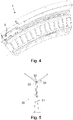
- the figure 3 shows a representation of the roller bearing 1 according to the exemplary embodiment from a viewing angle from which an anti-rotation element 18 arranged on the second base body 15 and an axial securing element 19 arranged on the first base body 15 are visible.
- the second base body 15 and/or the stripping elements 14 can be secured against undesired rotation in the circumferential direction of the roller bearing 1 via the anti-rotation element 18 .
- the anti-rotation element 18 is designed as an essentially plate-shaped element, which is formed from the second base body 15 by stamping and bending.
- a main extension plane of the anti-rotation element 18 is arranged perpendicular to a radial direction 101 of the roller bearing 1 .
- the anti-rotation element 18 engages in a groove 20 formed on the inner ring 4, so that a non-rotatable coupling of the second base body 15 and the inner ring 4 is achieved.
- a plurality of anti-rotation elements 18 are preferably arranged on the second base body 15 .
- the axial securing element 19 is designed like a hook and engages behind an area of the outer ring 5, so that the first base body 10 and/or the conveying elements 9 are positively fixed in the axial direction, i.e. in direction 100 of the axis of rotation.
- a plurality of axial securing elements 19 are preferably arranged on the first base body 10 .
- the first base body 10 can also have one or more anti-rotation elements 18 .
- one or more axial securing elements 19 can be provided on the second base body 15 .
- the conveying elements can be connected in a rotationally fixed manner to the inner ring of the roller bearing.
- the stripping elements are preferably provided on the outer ring of the roller bearing. In this case there is no contact between the conveying elements and the outer ring. Furthermore, in this modification there is no contact between the scraper elements and the inner ring.
- the conveying elements 9 and the stripping elements 14 can also have a shape that differs from that of the exemplary embodiment.
- the conveying elements 9 and/or the stripping elements 14 are curved, three-dimensionally shovel-shaped or triangular.
- the conveying elements 9 can be designed as conveying elements 9 that are separate from one another.
- the stripping elements can be configured as stripping elements 14 that are separate from one another.
- the stripping elements 14 can be connected individually to the inner ring 4 or it is possible to provide segments with a plurality of stripping elements 14 connected to one another in one piece.
- the exemplary embodiment described above can also be used when the roller bearing contains oil as a lubricant.
- the figure 5 shows an embodiment of a wind turbine 30 according to the invention.
- the wind turbine 30 has a tower 31 and a nacelle 32 which is mounted on the tower 31 so that it can rotate in azimuth via an azimuth rotary bearing.
- a rotor bearing is provided on the nacelle 32 , via which a rotor 33 of the wind turbine 30 is rotatably connected to the nacelle 32 .
- the rotor 33 has several, in particular three, rotor blades 34 .
- the rotor bearing of this wind turbine 30 is a roller bearing 1, as in the Figures 1 to 4 is shown. While the inner ring 4 of the roller bearing 1 is connected to the nacelle 32 in a torque-proof manner, the outer ring 5 of the roller bearing 1 is connected to the rotor 33 in a torque-proof manner. In this respect, the outer ring 5 of the roller bearing is rotatable about an axis of rotation relative to the inner ring 4 .
- the inner ring 4 can be connected to the rotor 33 in a rotationally fixed manner and the outer ring 5 can be connected to the nacelle 32 in a rotationally fixed manner. In such an alternative configuration, the inner ring 4 can be rotated relative to the outer ring 5 about an axis of rotation.
- the rotor bearing of the wind turbine also has at least one sealing element 6 arranged between the inner ring 4 and the outer ring 5 for sealing the interior 7 of the roller bearing 1 .
- the interior 7 can be filled with a lubricant.
- the rolling bearing 1 has a conveying element 9, which is arranged either on one of the inner ring 4 and the outer ring 5 so that it can rotate about the axis of rotation of the rolling bearing 1 such that between the conveying element 9 and the other of the inner ring 4 and the outer ring 5 game exists.
Landscapes
- Engineering & Computer Science (AREA)
- General Engineering & Computer Science (AREA)
- Mechanical Engineering (AREA)
- Rolling Contact Bearings (AREA)
Claims (14)
- Palier à roulement comportant une bague intérieure (4) et une bague extérieure (5), dans lequel soit la bague extérieure (5) peut tourner par rapport à la bague intérieure (4) autour d'un axe de rotation soit la bague intérieure (4) peut tourner par rapport à la bague extérieure (5) autour d'un axe de rotation, et comportant au moins un élément d'étanchéité (6) disposé entre la bague intérieure (4) et la bague extérieure (5) pour réaliser l'étanchéité d'un espace intérieur (7) du palier à roulement (1) pouvant être rempli d'un lubrifiant, dans lequel le palier à roulement (1) comprend un dispositif de refoulement (8) disposé dans l'espace intérieur (7) pour le refoulement du lubrifiant, dans lequel le dispositif de refoulement (8) comprend un élément de refoulement (9) pour le refoulement du lubrifiant, lequel élément de refoulement est disposé sur l'une parmi la bague intérieure (4) et la bague extérieure (5) de manière à pouvoir tourner autour de l'axe de rotation du palier à roulement (1) de telle sorte qu'un jeu existe entre l'élément de refoulement (9) et l'autre parmi la bague intérieure (4) et la bague extérieure (5), caractérisé en ce que le palier à roulement (1) comprend un élément racleur (14) pour le raclage de lubrifiant de l'élément de refoulement (9).
- Palier à roulement selon la revendication 1, dans lequel l'élément de refoulement (9) est déplaçable par rapport à l'élément racleur (14).
- Palier à roulement selon l'une des revendications précédentes, dans lequel l'élément de refoulement (9) et/ou l'élément racleur (14) est/sont réalisé(s) sous forme de lamelle(s).
- Palier à roulement selon l'une des revendications précédentes, dans lequel un plan d'étendue principale de l'élément de refoulement (9) et/ou de l'élément racleur (14) forme un angle aigu avec un plan axial du palier à roulement (1) contenant l'axe de rotation.
- Palier à roulement selon l'une des revendications 1 à 4, dans lequel l'élément de refoulement (9) et l'élément racleur (14) présentent une inclinaison opposée par rapport à un plan axial du palier à roulement (1) contenant l'axe de rotation.
- Palier à roulement selon l'une des revendications 1 à 5, dans lequel un plan d'étendue principale de l'élément de refoulement (9) et/ou de l'élément racleur (14) est disposé parallèlement à une direction radiale (101) du palier à roulement (1).
- Palier à roulement selon l'une des revendications précédentes, dans lequel l'élément racleur (14) est disposé sur l'autre parmi la bague intérieure (4) et la bague extérieure (5) et un jeu est prévu entre l'élément racleur (14) et l'une parmi la bague intérieure (4) et la bague extérieure (5).
- Palier à roulement selon l'une des revendications précédentes, le palier à roulement (1) comprenant plusieurs éléments de refoulement (9) et/ou plusieurs éléments racleurs (14).
- Palier à roulement selon l'une des revendications précédentes, le palier à roulement (1) comprenant plusieurs éléments de refoulement (9) qui sont disposés sur un premier corps de base (10) commun, en particulier annulaire.
- Palier à roulement selon l'une des revendications 1 à 9, le palier à roulement (1) comprenant plusieurs éléments racleurs (14) qui sont disposés sur un deuxième corps de base (15) commun, en particulier annulaire.
- Palier à roulement selon les revendications 10, dans lequel le deuxième corps de base (15) comprend des évidements (16) à travers lesquels du lubrifiant peut être conduit à partir des éléments racleurs (14) à travers le corps de base (15), en particulier en direction de corps de roulement (3) du palier à roulement (1) .
- Palier à roulement selon l'une des revendications précédentes, le palier à roulement (1) comprenant deux éléments d'étanchéité (6, 21) disposés entre la bague intérieure (4) et la bague extérieure (5) pour réaliser l'étanchéité de l'espace intérieur (7).
- Éolienne comportant une nacelle (32), un rotor (33) et un palier à roulement (1) par le biais duquel le rotor (33) est relié à la nacelle (32) de manière à pouvoir tourner, dans laquelle le palier à roulement (1) comprend soit- une bague intérieure (4) reliée à la nacelle (32) de manière bloquée en rotation et une bague extérieure (5) pouvant tourner par rapport à la bague intérieure (4) autour d'un axe de rotation et reliée au rotor (33) de manière bloquée en rotation soit- une bague extérieure (5) reliée à la nacelle (32) de manière bloquée en rotation et une bague intérieure (4) pouvant tourner par rapport à la bague extérieure (5) autour d'un axe de rotation et reliée au rotor (33) de manière bloquée en rotation,et comportant au moins un élément d'étanchéité (6) disposé entre la bague intérieure (4) et la bague extérieure (5) pour réaliser l'étanchéité d'un espace intérieur (7) du palier à roulement (1) pouvant être rempli d'un lubrifiant,caractérisée en ce quele palier à roulement (1) comprend un dispositif de refoulement (8) disposé dans l'espace intérieur (7) pour le refoulement du lubrifiant, le dispositif de refoulement (8) comprenant un élément de refoulement (9) pour le refoulement du lubrifiant, lequel élément de refoulement est disposé sur l'une parmi la bague intérieure (4) et la bague extérieure (5) de manière à pouvoir tourner autour de l'axe de rotation du palier à roulement (1) de telle sorte qu'un jeu existe entre l'élément de refoulement (9) et l'autre parmi la bague intérieure (4) et la bague extérieure (5), le palier à roulement (1) comprenant un élément racleur (14) pour le raclage de lubrifiant de l'élément de refoulement (9).
- Procédé de fonctionnement d'un palier à roulement (1) comportant une bague intérieure (4) et une bague extérieure (5), dans lequel soit la bague extérieure (5) peut tourner par rapport à la bague intérieure (4) autour d'un axe de rotation soit la bague intérieure (4) peut tourner par rapport à la bague extérieure (5) autour d'un axe de rotation, et comportant au moins un élément d'étanchéité (6) disposé entre la bague intérieure (4) et la bague extérieure (5) pour réaliser l'étanchéité d'un espace intérieur (7) du palier à roulement (1) rempli d'un lubrifiant, caractérisé en ce qu'un dispositif de refoulement (8) disposé dans l'espace intérieur (7) pour le refoulement du lubrifiant est prévu, le dispositif de refoulement (8) comprenant un élément de refoulement (9) pour le refoulement du lubrifiant, le lubrifiant étant refoulé par le biais de l'élément de refoulement (9), lequel est disposé sur l'une parmi la bague intérieure (4) et la bague extérieure (5) de manière à pouvoir tourner autour de l'axe de rotation du palier à roulement (1) de telle sorte qu'un jeu existe entre l'élément de refoulement (9) et l'autre parmi la bague intérieure (4) et la bague extérieure (5), le palier à roulement (1) comprenant un élément racleur (14) pour le raclage de lubrifiant de l'élément de refoulement (9), du lubrifiant refoulé par l'élément de refoulement (9) étant raclé de l'élément de refoulement (9) par le biais de l'élément racleur (14).
Applications Claiming Priority (3)
| Application Number | Priority Date | Filing Date | Title |
|---|---|---|---|
| DE102016101276 | 2016-01-26 | ||
| DE102016118054.8A DE102016118054A1 (de) | 2016-01-26 | 2016-09-23 | Wälzlager, Windkraftanlage und Verfahren zum Betrieb eines Wälzlagers |
| PCT/EP2017/051465 WO2017129578A1 (fr) | 2016-01-26 | 2017-01-25 | Palier à roulement, éolienne et procédé de fonctionnement d'un palier à roulement |
Publications (2)
| Publication Number | Publication Date |
|---|---|
| EP3408549A1 EP3408549A1 (fr) | 2018-12-05 |
| EP3408549B1 true EP3408549B1 (fr) | 2022-04-13 |
Family
ID=59296025
Family Applications (1)
| Application Number | Title | Priority Date | Filing Date |
|---|---|---|---|
| EP17701480.0A Active EP3408549B1 (fr) | 2016-01-26 | 2017-01-25 | Palier à roulement, éolienne et procédé de fonctionnement d'un palier à roulement |
Country Status (5)
| Country | Link |
|---|---|
| US (1) | US10495147B2 (fr) |
| EP (1) | EP3408549B1 (fr) |
| CN (1) | CN108603531B (fr) |
| DE (1) | DE102016118054A1 (fr) |
| WO (1) | WO2017129578A1 (fr) |
Families Citing this family (2)
| Publication number | Priority date | Publication date | Assignee | Title |
|---|---|---|---|---|
| EP4488517A1 (fr) * | 2023-07-03 | 2025-01-08 | Siemens Gamesa Renewable Energy A/S | Ensemble palier lubrifié |
| EP4600521A1 (fr) * | 2024-02-07 | 2025-08-13 | Nordex Energy SE & Co. KG | Ensemble palier et système de palier |
Citations (4)
| Publication number | Priority date | Publication date | Assignee | Title |
|---|---|---|---|---|
| US2848284A (en) * | 1957-06-20 | 1958-08-19 | Gen Motors Corp | Bearing oil scavenger |
| DE4329398A1 (de) * | 1993-01-13 | 1994-07-14 | Ford Werke Ag | Wälzlager |
| WO2010040027A2 (fr) * | 2008-10-02 | 2010-04-08 | The Timken Company | Système de purge de graisse |
| WO2011064002A1 (fr) * | 2009-11-24 | 2011-06-03 | Siemens Aktiengesellschaft | Récupérateur de graisse, nacelle d'éolienne et procédé de récupération de graisse excédentaire |
Family Cites Families (20)
| Publication number | Priority date | Publication date | Assignee | Title |
|---|---|---|---|---|
| US2045026A (en) | 1933-08-09 | 1936-06-23 | Universal Crusher Company | Bearing and oiling system therefor |
| GB697797A (en) | 1950-07-31 | 1953-09-30 | Lancashire Dynamo Holdings Ltd | Improvements in or relating to the lubrication of bearings |
| DE901359C (de) | 1951-11-16 | 1954-01-11 | Ver Kugellagerfabriken Ag | Fettmengenregler fuer Loslager |
| US5312191A (en) * | 1992-03-24 | 1994-05-17 | S W Industries | Lubrication mechanism for anti-friction bearings |
| US6324899B1 (en) * | 1998-04-02 | 2001-12-04 | Reliance Electric Technologies, Llc | Bearing-sensor integration for a lubrication analysis system |
| JP2004028306A (ja) | 2002-06-28 | 2004-01-29 | Ishikawajima Harima Heavy Ind Co Ltd | ころがり軸受 |
| US7635225B2 (en) * | 2005-08-31 | 2009-12-22 | Toshiba International Corporation | Positive displacement lubrication device |
| DE102007044496B4 (de) | 2007-09-18 | 2013-11-28 | Renk Aktiengesellschaft | Schmierstoffabstreifer sowie Gleitlageranordnung mit einem derartigen Schmierstoffabstreifer |
| DE202008001286U1 (de) | 2008-01-30 | 2008-03-27 | Schaeffler Kg | Wälzlagerschmiervorrichtung |
| DE102009014922A1 (de) | 2009-03-25 | 2010-09-30 | Ab Skf | Fettgeschmiertes zweireihiges Wälzlager und Lagersystem mit einem derartigen Wälzlager und einer Schmiervorrichtung |
| US8465207B2 (en) * | 2009-10-09 | 2013-06-18 | Dresser-Rand Company | Auxiliary bearing system with oil reservoir for magnetically supported rotor system |
| DE102009059842A1 (de) | 2009-12-21 | 2011-07-07 | Schaeffler Technologies GmbH & Co. KG, 91074 | Schleuderring mit Fangrinne |
| EP2565477A1 (fr) | 2011-09-02 | 2013-03-06 | Siemens Aktiengesellschaft | Système de roulement pour éolienne comprenant un racleur rotatif et un racleur stationnaire |
| EP2620642A1 (fr) | 2012-01-27 | 2013-07-31 | Siemens Aktiengesellschaft | Élément de racleur pour un roulement principal de commande directe d'une éolienne |
| JP5989454B2 (ja) | 2012-08-20 | 2016-09-07 | Ntn株式会社 | 転がり軸受装置 |
| WO2014037193A1 (fr) | 2012-09-06 | 2014-03-13 | Aktiebolaget Skf | Évacuation à lubrifiant pour palier |
| EP2762737B1 (fr) | 2013-01-31 | 2017-01-18 | Siemens Aktiengesellschaft | Eolienne à entraînement direct avec un roulement et procédé de collecte d'une fuite de lubrifiant d'un palier |
| DE102013216140B4 (de) | 2013-08-14 | 2015-03-26 | Aktiebolaget Skf | Lageranordnung |
| JP2015158227A (ja) | 2014-02-24 | 2015-09-03 | Ntn株式会社 | 複列円錐ころ軸受 |
| JP2015224701A (ja) | 2014-05-27 | 2015-12-14 | Ntn株式会社 | 転がり軸受 |
-
2016
- 2016-09-23 DE DE102016118054.8A patent/DE102016118054A1/de not_active Ceased
-
2017
- 2017-01-25 WO PCT/EP2017/051465 patent/WO2017129578A1/fr not_active Ceased
- 2017-01-25 CN CN201780008211.1A patent/CN108603531B/zh not_active Expired - Fee Related
- 2017-01-25 EP EP17701480.0A patent/EP3408549B1/fr active Active
- 2017-01-25 US US16/071,594 patent/US10495147B2/en not_active Expired - Fee Related
Patent Citations (4)
| Publication number | Priority date | Publication date | Assignee | Title |
|---|---|---|---|---|
| US2848284A (en) * | 1957-06-20 | 1958-08-19 | Gen Motors Corp | Bearing oil scavenger |
| DE4329398A1 (de) * | 1993-01-13 | 1994-07-14 | Ford Werke Ag | Wälzlager |
| WO2010040027A2 (fr) * | 2008-10-02 | 2010-04-08 | The Timken Company | Système de purge de graisse |
| WO2011064002A1 (fr) * | 2009-11-24 | 2011-06-03 | Siemens Aktiengesellschaft | Récupérateur de graisse, nacelle d'éolienne et procédé de récupération de graisse excédentaire |
Also Published As
| Publication number | Publication date |
|---|---|
| DE102016118054A1 (de) | 2017-07-27 |
| EP3408549A1 (fr) | 2018-12-05 |
| CN108603531A (zh) | 2018-09-28 |
| US20190032716A1 (en) | 2019-01-31 |
| WO2017129578A1 (fr) | 2017-08-03 |
| CN108603531B (zh) | 2020-01-14 |
| US10495147B2 (en) | 2019-12-03 |
Similar Documents
| Publication | Publication Date | Title |
|---|---|---|
| EP2694831B1 (fr) | Joint tournant pour utilisation sous l'eau et installation de production d'énergie hydraulique équipée d'un tel joint tournant | |
| EP2729712B1 (fr) | Roulement à rotule sur rouleaux avec dispositif d'étanchéité et ailette de stabilisation avec le roulement à rotule sur rouleaux | |
| EP2715162B2 (fr) | Couronne d'orientation | |
| EP3387298B1 (fr) | Joint d'étanchéité | |
| EP2816226A1 (fr) | Éolienne à palier lisse | |
| DE102012212792A1 (de) | Lageranordnung für eine Windkraftanlage | |
| DE102013200356A1 (de) | Zusammengesetzter Dichtungsträger für ein Direktantriebs-Hauptlager einer Windkraftanlage | |
| EP3894714B1 (fr) | Nacelle pour une éolienne | |
| DE102012215217A1 (de) | Lagersystem für eine Windkraftanlage, das einen drehbaren Abstreifer und einen stationären Abstreifer umfasst | |
| EP3721104B1 (fr) | Agencement de paliers a roulement | |
| EP3109493A1 (fr) | Agencement de palier a roulement et logement de pale pour une eolienne | |
| DE102019131245B4 (de) | Lageranordnung und Verfahren zum Montieren einer solchen | |
| EP3434917A1 (fr) | Dispositif palier destiné au logement d'un arbre de transmission | |
| DE102016118057B4 (de) | Wälzlager, Windkraftanlage und Verfahren zum Betrieb eines Wälzlagers | |
| DE102007019642B4 (de) | Fluiddynamisches Lagersystem | |
| DE102016118052B4 (de) | Wälzlager, Dichtelement und Windkraftanlage | |
| EP3094913B1 (fr) | Bague en x de conduction de lubrifiant | |
| EP3408549A1 (fr) | Palier à roulement, éolienne et procédé de fonctionnement d'un palier à roulement | |
| DE102018119132A1 (de) | Zweireihiges Kegelrollenlager | |
| EP3748182B1 (fr) | Agencement de palier à rouleaux doté d'un dispositif d'étanchéité permettant d'étanchéifier la fente de palier | |
| EP3870869B1 (fr) | Ensemble de paliers à roulement et éolienne | |
| DE102016118056B4 (de) | Wälzlager, Windkraftanlage mit einem Wälzlager und Verfahren zur Montage eines Wälzlagers | |
| EP3844392B1 (fr) | Ensemble de paliers pour une eolienne et eolienne | |
| DE102016118055B4 (de) | Wälzlager und Windkraftanlage | |
| DE102014224282B4 (de) | Berührungslose Dichtung und Maschinenelementanordnung hiermit |
Legal Events
| Date | Code | Title | Description |
|---|---|---|---|
| STAA | Information on the status of an ep patent application or granted ep patent |
Free format text: STATUS: UNKNOWN |
|
| STAA | Information on the status of an ep patent application or granted ep patent |
Free format text: STATUS: THE INTERNATIONAL PUBLICATION HAS BEEN MADE |
|
| PUAI | Public reference made under article 153(3) epc to a published international application that has entered the european phase |
Free format text: ORIGINAL CODE: 0009012 |
|
| STAA | Information on the status of an ep patent application or granted ep patent |
Free format text: STATUS: REQUEST FOR EXAMINATION WAS MADE |
|
| 17P | Request for examination filed |
Effective date: 20180827 |
|
| AK | Designated contracting states |
Kind code of ref document: A1 Designated state(s): AL AT BE BG CH CY CZ DE DK EE ES FI FR GB GR HR HU IE IS IT LI LT LU LV MC MK MT NL NO PL PT RO RS SE SI SK SM TR |
|
| AX | Request for extension of the european patent |
Extension state: BA ME |
|
| DAV | Request for validation of the european patent (deleted) | ||
| DAX | Request for extension of the european patent (deleted) | ||
| STAA | Information on the status of an ep patent application or granted ep patent |
Free format text: STATUS: EXAMINATION IS IN PROGRESS |
|
| 17Q | First examination report despatched |
Effective date: 20191125 |
|
| RAP1 | Party data changed (applicant data changed or rights of an application transferred) |
Owner name: THYSSENKRUPP AG Owner name: THYSSENKRUPP ROTHE ERDE GERMANY GMBH |
|
| GRAP | Despatch of communication of intention to grant a patent |
Free format text: ORIGINAL CODE: EPIDOSNIGR1 |
|
| STAA | Information on the status of an ep patent application or granted ep patent |
Free format text: STATUS: GRANT OF PATENT IS INTENDED |
|
| INTG | Intention to grant announced |
Effective date: 20211102 |
|
| GRAS | Grant fee paid |
Free format text: ORIGINAL CODE: EPIDOSNIGR3 |
|
| GRAA | (expected) grant |
Free format text: ORIGINAL CODE: 0009210 |
|
| STAA | Information on the status of an ep patent application or granted ep patent |
Free format text: STATUS: THE PATENT HAS BEEN GRANTED |
|
| AK | Designated contracting states |
Kind code of ref document: B1 Designated state(s): AL AT BE BG CH CY CZ DE DK EE ES FI FR GB GR HR HU IE IS IT LI LT LU LV MC MK MT NL NO PL PT RO RS SE SI SK SM TR |
|
| REG | Reference to a national code |
Ref country code: GB Ref legal event code: FG4D Free format text: NOT ENGLISH |
|
| REG | Reference to a national code |
Ref country code: CH Ref legal event code: EP |
|
| REG | Reference to a national code |
Ref country code: DE Ref legal event code: R096 Ref document number: 502017012956 Country of ref document: DE |
|
| REG | Reference to a national code |
Ref country code: IE Ref legal event code: FG4D Free format text: LANGUAGE OF EP DOCUMENT: GERMAN |
|
| REG | Reference to a national code |
Ref country code: AT Ref legal event code: REF Ref document number: 1483626 Country of ref document: AT Kind code of ref document: T Effective date: 20220515 |
|
| REG | Reference to a national code |
Ref country code: LT Ref legal event code: MG9D |
|
| REG | Reference to a national code |
Ref country code: NL Ref legal event code: MP Effective date: 20220413 |
|
| PG25 | Lapsed in a contracting state [announced via postgrant information from national office to epo] |
Ref country code: NL Free format text: LAPSE BECAUSE OF FAILURE TO SUBMIT A TRANSLATION OF THE DESCRIPTION OR TO PAY THE FEE WITHIN THE PRESCRIBED TIME-LIMIT Effective date: 20220413 |
|
| PG25 | Lapsed in a contracting state [announced via postgrant information from national office to epo] |
Ref country code: SE Free format text: LAPSE BECAUSE OF FAILURE TO SUBMIT A TRANSLATION OF THE DESCRIPTION OR TO PAY THE FEE WITHIN THE PRESCRIBED TIME-LIMIT Effective date: 20220413 Ref country code: PT Free format text: LAPSE BECAUSE OF FAILURE TO SUBMIT A TRANSLATION OF THE DESCRIPTION OR TO PAY THE FEE WITHIN THE PRESCRIBED TIME-LIMIT Effective date: 20220816 Ref country code: NO Free format text: LAPSE BECAUSE OF FAILURE TO SUBMIT A TRANSLATION OF THE DESCRIPTION OR TO PAY THE FEE WITHIN THE PRESCRIBED TIME-LIMIT Effective date: 20220713 Ref country code: LT Free format text: LAPSE BECAUSE OF FAILURE TO SUBMIT A TRANSLATION OF THE DESCRIPTION OR TO PAY THE FEE WITHIN THE PRESCRIBED TIME-LIMIT Effective date: 20220413 Ref country code: HR Free format text: LAPSE BECAUSE OF FAILURE TO SUBMIT A TRANSLATION OF THE DESCRIPTION OR TO PAY THE FEE WITHIN THE PRESCRIBED TIME-LIMIT Effective date: 20220413 Ref country code: GR Free format text: LAPSE BECAUSE OF FAILURE TO SUBMIT A TRANSLATION OF THE DESCRIPTION OR TO PAY THE FEE WITHIN THE PRESCRIBED TIME-LIMIT Effective date: 20220714 Ref country code: FI Free format text: LAPSE BECAUSE OF FAILURE TO SUBMIT A TRANSLATION OF THE DESCRIPTION OR TO PAY THE FEE WITHIN THE PRESCRIBED TIME-LIMIT Effective date: 20220413 Ref country code: ES Free format text: LAPSE BECAUSE OF FAILURE TO SUBMIT A TRANSLATION OF THE DESCRIPTION OR TO PAY THE FEE WITHIN THE PRESCRIBED TIME-LIMIT Effective date: 20220413 Ref country code: BG Free format text: LAPSE BECAUSE OF FAILURE TO SUBMIT A TRANSLATION OF THE DESCRIPTION OR TO PAY THE FEE WITHIN THE PRESCRIBED TIME-LIMIT Effective date: 20220713 |
|
| PG25 | Lapsed in a contracting state [announced via postgrant information from national office to epo] |
Ref country code: RS Free format text: LAPSE BECAUSE OF FAILURE TO SUBMIT A TRANSLATION OF THE DESCRIPTION OR TO PAY THE FEE WITHIN THE PRESCRIBED TIME-LIMIT Effective date: 20220413 Ref country code: PL Free format text: LAPSE BECAUSE OF FAILURE TO SUBMIT A TRANSLATION OF THE DESCRIPTION OR TO PAY THE FEE WITHIN THE PRESCRIBED TIME-LIMIT Effective date: 20220413 Ref country code: LV Free format text: LAPSE BECAUSE OF FAILURE TO SUBMIT A TRANSLATION OF THE DESCRIPTION OR TO PAY THE FEE WITHIN THE PRESCRIBED TIME-LIMIT Effective date: 20220413 Ref country code: IS Free format text: LAPSE BECAUSE OF FAILURE TO SUBMIT A TRANSLATION OF THE DESCRIPTION OR TO PAY THE FEE WITHIN THE PRESCRIBED TIME-LIMIT Effective date: 20220813 |
|
| REG | Reference to a national code |
Ref country code: DE Ref legal event code: R097 Ref document number: 502017012956 Country of ref document: DE |
|
| PG25 | Lapsed in a contracting state [announced via postgrant information from national office to epo] |
Ref country code: SM Free format text: LAPSE BECAUSE OF FAILURE TO SUBMIT A TRANSLATION OF THE DESCRIPTION OR TO PAY THE FEE WITHIN THE PRESCRIBED TIME-LIMIT Effective date: 20220413 Ref country code: SK Free format text: LAPSE BECAUSE OF FAILURE TO SUBMIT A TRANSLATION OF THE DESCRIPTION OR TO PAY THE FEE WITHIN THE PRESCRIBED TIME-LIMIT Effective date: 20220413 Ref country code: RO Free format text: LAPSE BECAUSE OF FAILURE TO SUBMIT A TRANSLATION OF THE DESCRIPTION OR TO PAY THE FEE WITHIN THE PRESCRIBED TIME-LIMIT Effective date: 20220413 Ref country code: EE Free format text: LAPSE BECAUSE OF FAILURE TO SUBMIT A TRANSLATION OF THE DESCRIPTION OR TO PAY THE FEE WITHIN THE PRESCRIBED TIME-LIMIT Effective date: 20220413 Ref country code: DK Free format text: LAPSE BECAUSE OF FAILURE TO SUBMIT A TRANSLATION OF THE DESCRIPTION OR TO PAY THE FEE WITHIN THE PRESCRIBED TIME-LIMIT Effective date: 20220413 Ref country code: CZ Free format text: LAPSE BECAUSE OF FAILURE TO SUBMIT A TRANSLATION OF THE DESCRIPTION OR TO PAY THE FEE WITHIN THE PRESCRIBED TIME-LIMIT Effective date: 20220413 |
|
| PLBE | No opposition filed within time limit |
Free format text: ORIGINAL CODE: 0009261 |
|
| STAA | Information on the status of an ep patent application or granted ep patent |
Free format text: STATUS: NO OPPOSITION FILED WITHIN TIME LIMIT |
|
| 26N | No opposition filed |
Effective date: 20230116 |
|
| PG25 | Lapsed in a contracting state [announced via postgrant information from national office to epo] |
Ref country code: AL Free format text: LAPSE BECAUSE OF FAILURE TO SUBMIT A TRANSLATION OF THE DESCRIPTION OR TO PAY THE FEE WITHIN THE PRESCRIBED TIME-LIMIT Effective date: 20220413 |
|
| PG25 | Lapsed in a contracting state [announced via postgrant information from national office to epo] |
Ref country code: SI Free format text: LAPSE BECAUSE OF FAILURE TO SUBMIT A TRANSLATION OF THE DESCRIPTION OR TO PAY THE FEE WITHIN THE PRESCRIBED TIME-LIMIT Effective date: 20220413 |
|
| REG | Reference to a national code |
Ref country code: DE Ref legal event code: R119 Ref document number: 502017012956 Country of ref document: DE |
|
| REG | Reference to a national code |
Ref country code: CH Ref legal event code: PL |
|
| GBPC | Gb: european patent ceased through non-payment of renewal fee |
Effective date: 20230125 |
|
| PG25 | Lapsed in a contracting state [announced via postgrant information from national office to epo] |
Ref country code: LU Free format text: LAPSE BECAUSE OF NON-PAYMENT OF DUE FEES Effective date: 20230125 |
|
| REG | Reference to a national code |
Ref country code: BE Ref legal event code: MM Effective date: 20230131 |
|
| PG25 | Lapsed in a contracting state [announced via postgrant information from national office to epo] |
Ref country code: LI Free format text: LAPSE BECAUSE OF NON-PAYMENT OF DUE FEES Effective date: 20230131 Ref country code: GB Free format text: LAPSE BECAUSE OF NON-PAYMENT OF DUE FEES Effective date: 20230125 Ref country code: DE Free format text: LAPSE BECAUSE OF NON-PAYMENT OF DUE FEES Effective date: 20230801 Ref country code: CH Free format text: LAPSE BECAUSE OF NON-PAYMENT OF DUE FEES Effective date: 20230131 |
|
| PG25 | Lapsed in a contracting state [announced via postgrant information from national office to epo] |
Ref country code: FR Free format text: LAPSE BECAUSE OF NON-PAYMENT OF DUE FEES Effective date: 20230131 Ref country code: BE Free format text: LAPSE BECAUSE OF NON-PAYMENT OF DUE FEES Effective date: 20230131 |
|
| PG25 | Lapsed in a contracting state [announced via postgrant information from national office to epo] |
Ref country code: IT Free format text: LAPSE BECAUSE OF FAILURE TO SUBMIT A TRANSLATION OF THE DESCRIPTION OR TO PAY THE FEE WITHIN THE PRESCRIBED TIME-LIMIT Effective date: 20220413 Ref country code: IE Free format text: LAPSE BECAUSE OF NON-PAYMENT OF DUE FEES Effective date: 20230125 |
|
| REG | Reference to a national code |
Ref country code: AT Ref legal event code: MM01 Ref document number: 1483626 Country of ref document: AT Kind code of ref document: T Effective date: 20230125 |
|
| PG25 | Lapsed in a contracting state [announced via postgrant information from national office to epo] |
Ref country code: AT Free format text: LAPSE BECAUSE OF NON-PAYMENT OF DUE FEES Effective date: 20230125 |
|
| PG25 | Lapsed in a contracting state [announced via postgrant information from national office to epo] |
Ref country code: AT Free format text: LAPSE BECAUSE OF NON-PAYMENT OF DUE FEES Effective date: 20230125 |
|
| PG25 | Lapsed in a contracting state [announced via postgrant information from national office to epo] |
Ref country code: MC Free format text: LAPSE BECAUSE OF FAILURE TO SUBMIT A TRANSLATION OF THE DESCRIPTION OR TO PAY THE FEE WITHIN THE PRESCRIBED TIME-LIMIT Effective date: 20220413 |
|
| PG25 | Lapsed in a contracting state [announced via postgrant information from national office to epo] |
Ref country code: MC Free format text: LAPSE BECAUSE OF FAILURE TO SUBMIT A TRANSLATION OF THE DESCRIPTION OR TO PAY THE FEE WITHIN THE PRESCRIBED TIME-LIMIT Effective date: 20220413 |
|
| PG25 | Lapsed in a contracting state [announced via postgrant information from national office to epo] |
Ref country code: BG Free format text: LAPSE BECAUSE OF FAILURE TO SUBMIT A TRANSLATION OF THE DESCRIPTION OR TO PAY THE FEE WITHIN THE PRESCRIBED TIME-LIMIT Effective date: 20220413 |
|
| PG25 | Lapsed in a contracting state [announced via postgrant information from national office to epo] |
Ref country code: BG Free format text: LAPSE BECAUSE OF FAILURE TO SUBMIT A TRANSLATION OF THE DESCRIPTION OR TO PAY THE FEE WITHIN THE PRESCRIBED TIME-LIMIT Effective date: 20220413 |
|
| PG25 | Lapsed in a contracting state [announced via postgrant information from national office to epo] |
Ref country code: CY Free format text: LAPSE BECAUSE OF FAILURE TO SUBMIT A TRANSLATION OF THE DESCRIPTION OR TO PAY THE FEE WITHIN THE PRESCRIBED TIME-LIMIT; INVALID AB INITIO Effective date: 20170125 |
|
| PG25 | Lapsed in a contracting state [announced via postgrant information from national office to epo] |
Ref country code: HU Free format text: LAPSE BECAUSE OF FAILURE TO SUBMIT A TRANSLATION OF THE DESCRIPTION OR TO PAY THE FEE WITHIN THE PRESCRIBED TIME-LIMIT; INVALID AB INITIO Effective date: 20170125 |
|
| PG25 | Lapsed in a contracting state [announced via postgrant information from national office to epo] |
Ref country code: TR Free format text: LAPSE BECAUSE OF FAILURE TO SUBMIT A TRANSLATION OF THE DESCRIPTION OR TO PAY THE FEE WITHIN THE PRESCRIBED TIME-LIMIT Effective date: 20220413 |