EP3408660B1 - Capteur de gaz électrochimique - Google Patents
Capteur de gaz électrochimique Download PDFInfo
- Publication number
- EP3408660B1 EP3408660B1 EP16887165.5A EP16887165A EP3408660B1 EP 3408660 B1 EP3408660 B1 EP 3408660B1 EP 16887165 A EP16887165 A EP 16887165A EP 3408660 B1 EP3408660 B1 EP 3408660B1
- Authority
- EP
- European Patent Office
- Prior art keywords
- housing
- tab
- gaps
- electrolyte
- electrodes
- Prior art date
- Legal status (The legal status is an assumption and is not a legal conclusion. Google has not performed a legal analysis and makes no representation as to the accuracy of the status listed.)
- Active
Links
Images



Classifications
-
- G—PHYSICS
- G01—MEASURING; TESTING
- G01N—INVESTIGATING OR ANALYSING MATERIALS BY DETERMINING THEIR CHEMICAL OR PHYSICAL PROPERTIES
- G01N27/00—Investigating or analysing materials by the use of electric, electrochemical, or magnetic means
- G01N27/26—Investigating or analysing materials by the use of electric, electrochemical, or magnetic means by investigating electrochemical variables; by using electrolysis or electrophoresis
- G01N27/403—Cells and electrode assemblies
- G01N27/413—Concentration cells using liquid electrolytes measuring currents or voltages in voltaic cells
-
- G—PHYSICS
- G01—MEASURING; TESTING
- G01N—INVESTIGATING OR ANALYSING MATERIALS BY DETERMINING THEIR CHEMICAL OR PHYSICAL PROPERTIES
- G01N27/00—Investigating or analysing materials by the use of electric, electrochemical, or magnetic means
- G01N27/26—Investigating or analysing materials by the use of electric, electrochemical, or magnetic means by investigating electrochemical variables; by using electrolysis or electrophoresis
- G01N27/403—Cells and electrode assemblies
- G01N27/404—Cells with anode, cathode and cell electrolyte on the same side of a permeable membrane which separates them from the sample fluid, e.g. Clark-type oxygen sensors
-
- G—PHYSICS
- G01—MEASURING; TESTING
- G01N—INVESTIGATING OR ANALYSING MATERIALS BY DETERMINING THEIR CHEMICAL OR PHYSICAL PROPERTIES
- G01N27/00—Investigating or analysing materials by the use of electric, electrochemical, or magnetic means
- G01N27/26—Investigating or analysing materials by the use of electric, electrochemical, or magnetic means by investigating electrochemical variables; by using electrolysis or electrophoresis
- G01N27/403—Cells and electrode assemblies
- G01N27/404—Cells with anode, cathode and cell electrolyte on the same side of a permeable membrane which separates them from the sample fluid, e.g. Clark-type oxygen sensors
- G01N27/4045—Cells with anode, cathode and cell electrolyte on the same side of a permeable membrane which separates them from the sample fluid, e.g. Clark-type oxygen sensors for gases other than oxygen
-
- G—PHYSICS
- G01—MEASURING; TESTING
- G01N—INVESTIGATING OR ANALYSING MATERIALS BY DETERMINING THEIR CHEMICAL OR PHYSICAL PROPERTIES
- G01N27/00—Investigating or analysing materials by the use of electric, electrochemical, or magnetic means
- G01N27/26—Investigating or analysing materials by the use of electric, electrochemical, or magnetic means by investigating electrochemical variables; by using electrolysis or electrophoresis
- G01N27/416—Systems
- G01N27/49—Systems involving the determination of the current at a single specific value, or small range of values, of applied voltage for producing selective measurement of one or more particular ionic species
Definitions
- CO sensors may comprise electrochemical sensors. Electrochemical sensors, in general, may employ a chemical reaction to convert CO to carbon dioxide (CO2) to create a chemical imbalance in a portion of the cell which in turn generates a current indicative of the amount of CO present.
- CO2 carbon dioxide
- US2015/122649 discloses a sensor with a sensor housing or body, a plastic molded table positioned in the sensor housing; and a counter electrode carried on a first end of the table.
- US2007/0131550 discloses an electrochemical gas sensor that can restrict to the extent possible interference errors.
- US6, 454, 923 discloses a gas sensor which is particularly well suited as a carbon monoxide (CO) sensor in a self test gas sensor.
- CO carbon monoxide
- component or feature may,” “can,” “could,” “should,” “would,” “preferably,” “possibly,” “typically,” “optionally,” “for example,” “often,” or “might” (or other such language) be included or have a characteristic, that particular component or feature is not required to be included or to have the characteristic. Such component or feature may be optionally included in some embodiments, or it may be excluded.
- the sensor 100 may comprise a CO sensor.
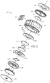
- the sensor 100 comprises a housing 102, wherein the housing 102 comprises gaps 108 to allow one or more wires/leads (not shown) to pass through into the housing 102.
- the wire may comprise platinum wires, wherein the wires may serve as current collectors.
- the housing 102 may also comprise a frame 130, wherein a connector printed circuit board (PCB) 104 may be operable to fit within the frame 130.
- PCB connector printed circuit board
- the connector PCB 104 may be attached to the one or more wires.
- the sensor 100 may comprise a bottom cover or label 106.
- the sensor 100 generally comprises a housing 102 defining a cavity or reservoir 103 designed to hold an electrolyte solution.
- a working (or sensing) electrode 110 can be placed between an opening 127 and the reservoir 103, wherein the opening 127 allows a gas to be detected to enter the housing 102.
- a counter electrode 116 is, and a reference electrode 114 can be, positioned within the reservoir. When the gas reacts within the reservoir 103, an electrical current and/or potential can be developed between the electrodes to provide an indication of the concentration of the gas.
- a reference electrode 114 may also be positioned within the reservoir 103 to provide a reference for the detected current and potential between the working electrode 110 and the counter electrode 116.
- the housing 102 can generally be formed from any material that is substantially inert to the electrolyte and gas being measured.
- the housing 102 can be formed from a polymeric material, a metal, or a ceramic.
- the housing can be formed from a material including, but not limited to, acrylonitrile butadiene styrene (ABS), polyphenylene oxide (PPO), polystyrene (PS), polypropylene (PP), polyethylene (PE) (e.g., high density polyethylene (HDPE)), polyphenylene ether (PPE), or any combination or blend thereof.
- ABS acrylonitrile butadiene styrene
- PPO polyphenylene oxide
- PS polystyrene
- PP polypropylene
- PE polyethylene
- PE polyethylene
- PPE polyphenylene ether
- One or more openings 127 can be formed through the housing 102 to allow the ambient gas to enter the housing 102 and/or allow any gases generated within the housing to escape.
- the sensor 100 may comprise at least one inlet opening 127 to allow the ambient gas to enter the housing 102.
- the opening 127 can be disposed in a cap 126 (or top cover) when a cap is present and/or in a wall of the housing 102.
- the sensor 100 may comprise a top cover 126 operable to fit into the housing 102 and at least partially seal the sensor 100.
- the top cover 126 may comprise an opening to allow a gas flow to enter the sensor 100.
- the sensor 100 may comprise a dust cover 128 located around the opening 127 to the sensor 100, operable to prevent unwanted particles from entering the sensor 100.
- the sensor 100 may comprise a carbon filter 124 operable to filter ambient air flowing into the housing 102 via the opening 127.
- the carbon filter 124 may function as a diffusion barrier to restrict the flow of gas (e.g., carbon monoxide, hydrogen sulfide, etc.) to the working electrode 110.
- a diffusion barrier can be created by forming the opening 127 as a capillary and/or a film or membrane can be used to control the mass flow rate through the one or more openings 127.
- the reservoir 103 comprises the counter electrode 116, the reference electrode 114, and the working electrode 110.
- the electrolyte is contained within the reservoir 103, and the counter electrode 116, (optionally the reference electrode 114), and the working electrode 110 are in electrical contact through the electrolyte.
- one or more porous separators 112, 118 or other porous structures can be used to retain the electrolyte in contact with the electrodes.
- the separators 112, 118 can comprise a porous member that acts as a wick for the retention and transport of the electrolyte between the reservoir and the electrodes while being electrically insulating to prevent shorting due to direct contact between any two electrodes.
- One or more of the porous separator 112, 118 can extend into the reservoir to provide the electrolyte a path to the electrodes.
- a separator 112 can be disposed between the counter electrode 116 and the reference electrode 114, and a separator 112 can be disposed between the reference electrode 114 and the working electrode 110.
- One or more of the separators 112, 118 can comprise a nonwoven porous material (e.g., a porous felt member), a woven porous material, a porous polymer (e.g., an open cell foam, a solid porous plastic, etc.), or the like, and is generally chemically inert with respect to the electrolyte and the materials forming the electrodes.
- the separator 112, 118 can be formed from various materials that are substantially chemically inert to the electrolyte including, but not limited to, glass (e.g., a glass mat, glass fiber), polymer (plastic discs), ceramics, or the like.
- the electrolyte can be any conventional aqueous acidic electrolyte such as sulfuric acid, phosphoric acid, or a neutral ionic solution such as a salt solution (e.g., a lithium salt such as lithium chloride, etc.), or any combination thereof.
- the electrolyte can comprise sulfuric acid having a molar concentration between about 3 M to about 12 M. Since sulfuric acid is hygroscopic, the concentration can vary from about 10 to about 70 wt% (1 to 11.5 molar) over a relative humidity (RH) range of the environment of about 3 to about 95%.
- the electrolyte can comprise phosphoric acid having a concentration in an aqueous solution between about 30% to about 60% H 3 PO 4 by weight.
- the electrolyte can include a lithium chloride salt having about 30% to about 60% LiCI by weight, with the balance being an aqueous solution.
- the electrolyte may be in the form of a solid polymer electrolyte which comprises an ionic exchange membrane.
- the electrolyte can be in the form of a free liquid, disposed in a matrix or slurry such as glass fibers (e.g., the separator 118, the separator 112, etc.), or disposed in the form of a semi-solid or solid gel.
- the working electrode 110 is disposed within the housing 102.
- the gas entering the sensor 100 can contact one side of the working electrode 110 and pass through working electrode 110 to reach the interface between the working electrode 110 and the electrolyte.
- the gas can then react to generate the current indicative of the gas concentration.
- the counter electrode 116 is disposed within the housing 102.
- the counter electrode 116 can comprise a substrate or membrane such as a polytetrafluoroethylene (PTFE) membrane, a GEFC-IES membrane, a Nafion ® membrane, or the like having a catalytic material disposed thereon.
- the catalytic material can be mixed and disposed on the membrane using any suitable process such as rolling, coating, screen printing, or the like to apply the catalytic material on the membrane.
- the catalytic material for the counter electrode 116 can comprise a noble metal such as gold (Au), platinum (Pt), ruthenium (Ru), rhodium (Rh), Iridium (Ir), oxides thereof, or any combination thereof.
- the reference electrode 114 can be disposed within the housing 102.
- the reference electrode 114 can comprise a substrate or membrane such as a PTFE membrane, a GEFC-IES membrane, a Nafion ® membrane, or the like having a catalytic material disposed thereon.
- the catalytic material can be mixed with a hydrophobic material (e.g., PTFE, etc.) and disposed on the PTFE membrane.
- the catalytic material used with the reference electrode 114 can comprise a noble metal such as gold (Au), platinum (Pt), ruthenium (Ru), rhodium (Rh), Iridium (Ir), oxides thereof, or any combination thereof.
- the catalytic material used to form the reference electrode can comprise a Pt-Ru mixture that is screen printed on the membrane, where the membrane can be a GEFC-IES membrane. While illustrated in FIG. 2 as having the reference electrode 114, some embodiments of the electrochemical sensor may not include a reference electrode 114.
- the separator 118 may comprise a wick 118 operable to collect electrolyte and ensure that the other elements in the sensor 100 remain wetted.
- the sensor 100 may comprise a support 120 for the stack of electrodes.
- the support 120 may create a cavity within the sensor 100, wherein electrolyte (or acid) may be located within the cavity of the support 120.
- the sensor 100 may comprise a bottom cover 122 operable to fit into the housing 102 and seal the bottom of the sensor 100.
- the sensor 100 may comprise one or more label 106, 107 located on the exterior of the sensor 100.
- leads are electrically coupled to the working electrode 110, (optionally to the reference electrode 114), and to the counter electrode 116.
- the lead contacting the working electrode 110 can contact either side of the working electrode 110 since the substrate comprises an electrically conductive material. In order to avoid the corrosive effects of the electrolyte, the lead contacting the working electrode can contact the side of the working electrode 110 that is not in contact with the electrolyte.
- Leads may be similarly electrically coupled to the counter electrode 116 and the reference electrode 114.
- the leads can be electrically coupled to external connection pins to provide an electrical connection to external processing circuitry (or a PCB) 104.
- the external circuitry 104 can detect the current and/or potential difference between the electrodes and convert the current into a corresponding gas concentration.
- the leads pass through gaps 108 in the housing 102 between the external circuitry 104 and the electrodes.
- the gaps 108 are sealed with epoxy to prevent electrolyte from leaking out of the sensor 100 via the gaps 108. Therefore, when the sensor 100 is in operation, the epoxy may be in contact with the electrolyte.
- the epoxy material may react with the electrolyte to form volatile organic compounds (VOCs.) This may disrupt the sensor 100, possibly causing false alarms and increasing the baseline reading for the sensor. In some embodiments, this reaction may occur around 50 C or above.
- the counter electrode 116 comprises a tab 117 extending from a portion of the counter electrode 116.
- the tab 117 may be incorporated into the PTFE membrane of the counter electrode 116.
- the tab 117 is operable to prevent the epoxy filling the gaps 108 from contacting the electrolyte located within the reservoir 103.
- the tab 117 may be approximately 4 millimeters in width.
- the gaps 108 may be within approximately 4 millimeters of each other, such that the width of the tab 117 covers all of the gaps 108.
- the distance between the extremities of the plurality of gaps 108 may be less than the width of the tab 117.
- the housing 102 and the counter electrode 116 are shown.
- the tab 117 of the counter electrode 116 is operable to cover a portion of the gaps 108 into the housing 102, thereby preventing the epoxy sealing the gaps 108 to contact the electrolyte within the housing 102.
- the gaps 108 may be located near one another around the edge of the housing 102, allowing the tab 117 to be located on only a portion of the counter electrode 116, covering the gaps 108.
- the housing 102 may comprise a slot 132 cut into the interior of the housing 102. The slot 132 may be located about the gaps 108.
- the tab 117 of the counter electrode 116 may be shaped to fit within the slot 132.
- the support 120 (shown in FIG. 2 ) may fix the tab 117 in place within the slot 132.
- the leads (described above) pass through the gaps 108 in the housing, and may pass through the slot 132 around the tab 117 and contact the electrodes as necessary.
- the counter electrode 116 may be in place within the housing 102, such that the tab 117 is filling the slot 132. Then, the epoxy may fill the gaps 108 but stop when it contacts the tab 117.
- the tab 117 may not completely prevent the electrolyte from contacting the epoxy. In this case, the tab 117 may reduce the interaction between the electrolyte and the epoxy. Also, in some embodiments, if the epoxy and electrolyte react, the tab 117 may impede the path of any gases formed by the reaction from entering the rest of the sensor 100 and disrupting the sensor 100.
- FIGS. 4A-4B illustrate an assembly method for the housing 102 and the counter electrode 116.
- leads 107 are inserted into the housing 102 via the gaps 108.
- the tab 117 of the counter electrode 116 is fitted into the slot 132 (not shown).
- FIG. 4B the tab 117 is in place within the housing 102, and the gaps 108 are filled with sealing material 109 (epoxy).
- FIGS. 4A-4B show only a portion of the assembly method for the entire gas sensor 100.
- embodiments may include a method of manufacture for a gas sensor, wherein the method includes placing leads through gaps in a housing, assembling at least a counter electrode within the housing, wherein the counter electrode comprises a tab placed proximate to the gaps, and then filling the gaps (around the leads) with epoxy to seal the gaps, wherein the tab prevents the epoxy from entering the interior of the housing.
- Embodiments of the disclosure may comprise an electrochemical gas sensor comprising a housing; an electrolyte disposed within the housing; a plurality of electrodes in contact with the electrolyte within the housing, wherein the plurality of electrodes comprise a working electrode and a counter electrodes, and wherein the plurality of electrodes contact a plurality of leads passing through one or more gaps in the housing, and wherein the gaps in the housing are sealed with a sealing material; and a tab located within the housing proximate to the gaps in the housing, operable to prevent the sealing material from entering the interior of the housing.
- the tab is incorporated into the counter electrode. In some embodiments, the tab is incorporated into the PTFE membrane of the counter electrode. In embodiments, the tab extends perpendicular to the surface of the counter electrode. In some embodiments, the tab comprises a PTFE material. In some embodiments, the plurality of electrodes further comprises a reference electrode. In some embodiments, the gas sensor may further comprise an external circuitry operable to fit into a portion of the housing and contact the plurality of leads. In some embodiments, the gas sensor may further comprise a support operable to support the plurality of electrodes and create a cavity operable to hold the electrolyte. In some embodiments, the housing comprises a slot located about the gaps, and wherein the tab fits within the slot in the housing. In embodiments, the sealing material comprises an epoxy material. In some embodiments, the gaps are located within approximately 4 millimeters of each other. In some embodiments, the tab is approximately 4 millimeters in width.
- Additional embodiments of the disclosure may comprise a method for assembling a gas sensor comprising providing a housing, wherein the housing comprises one or more gaps and a slot on the interior of the housing; inserting a plurality of leads into the housing via the gaps, wherein a portion of the leads extend out of the housing; placing a tab within the housing, wherein the tab fits into the slot of the housing, and wherein the tab is located proximate to the one or more gaps; and filling the gaps with a sealing material, wherein the tab is operable to prevent the sealing material from entering the interior of the housing.
- the method may further comprise placing an electrolyte within the housing; and placing a plurality of electrodes within the housing, wherein the plurality of electrodes are in contact with the electrolyte, and wherein the plurality of electrodes are in contact with the plurality of leads.
- the tab is incorporated into an electrode.
- an electrochemical gas sensor comprising a housing; an electrolyte disposed within the housing; a plurality of electrodes in contact with the electrolyte within the housing; a plurality of leads passing through one or more gaps in the housing, wherein the leads contact the plurality of electrodes, and wherein the gaps in the housing are sealed with a sealing material; and a tab located within the housing proximate to the gaps in the housing, operable to prevent the sealing material from entering the interior of the housing.
- the tab is incorporated into the counter electrode. In some embodiments, the tab is incorporated into the PTFE membrane of the counter electrode. In some embodiments, the housing comprises a slot located about the gaps, and wherein the tab fits within the slot in the housing. In some embodiments, the gaps are located within approximately 4 millimeters of each other.
Landscapes
- Chemical & Material Sciences (AREA)
- Life Sciences & Earth Sciences (AREA)
- Health & Medical Sciences (AREA)
- Physics & Mathematics (AREA)
- Chemical Kinetics & Catalysis (AREA)
- Electrochemistry (AREA)
- Molecular Biology (AREA)
- Analytical Chemistry (AREA)
- Biochemistry (AREA)
- General Health & Medical Sciences (AREA)
- General Physics & Mathematics (AREA)
- Immunology (AREA)
- Pathology (AREA)
- Measuring Oxygen Concentration In Cells (AREA)
Claims (11)
- Capteur de gaz électrochimique (100) comprenant :un boîtier (102) ;un électrolyte disposé à l'intérieur du boîtier (102) ;une pluralité de conducteurs (107) ;un matériau d'étanchéité (109) ;une pluralité d'électrodes (110, 116) en contact avec l'électrolyte à l'intérieur du boîtier (102), la pluralité d'électrodes (110, 116) comprenant une électrode de travail (110) et une contre-électrode (116), et la pluralité d'électrodes (110, 116) entrant en contact avec la pluralité de conducteurs (107) traversant un ou plusieurs espaces (108) dans le boîtier (102) et les espaces (108) du boîtier (102) étant rendus étanches au moyen du matériau d'étanchéité (109), le matériau d'étanchéité (109) comprenant un matériau époxy ; etune languette (117) incorporée dans la contre-électrode (116) et située à l'intérieur du boîtier (102), la languette (117) s'étendant perpendiculairement à la surface de la contre-électrode (116) et recouvrant au moins une partie des espaces (108) pour empêcher la pénétration du matériau d'étanchéité (109) à l'intérieur du boîtier (102).
- Capteur de gaz (100) selon la revendication 1, dans lequel la languette (117) est incorporée dans la membrane de polytétrafluoroéthylène de la contre-électrode (116).
- Capteur de gaz (100) selon la revendication 1, dans lequel la languette (117) comprend un matériau de polytétrafluoroéthylène.
- Capteur de gaz (100) selon la revendication 1, dans lequel la pluralité d'électrodes comprend en outre une électrode de référence (114).
- Capteur de gaz (100) selon la revendication 1, comprenant en outre une circuiterie externe (104) utilisable pour s'ajuster dans une partie du boîtier (102) et pour entrer en contact avec la pluralité de conducteurs (107).
- Capteur de gaz (100) selon la revendication 1, comprenant en outre un support (120) utilisable pour soutenir la pluralité d'électrodes (110, 116) et pour créer une cavité utilisable pour contenir l'électrolyte.
- Capteur de gaz (100) selon la revendication 1, dans lequel le boîtier (102) comprend une fente (132) située autour des espaces (108) et dans lequel la languette (117) s'ajuste à l'intérieur de la fente (132) dans le boîtier (102).
- Capteur de gaz (100) selon la revendication 1, dans lequel les espaces (108) sont situés à moins de 4 millimètres les uns des autres.
- Capteur de gaz (100) selon la revendication 1, dans lequel la languette (117) a une largeur de 4 millimètres.
- Procédé d'assemblage d'un capteur de gaz comprenant :l'utilisation d'un boîtier (102), le boîtier (102) comprenant un ou plusieurs espaces (108) et une fente (132) à l'intérieur du boîtier (102) ;l'insertion d'une pluralité de conducteurs (107) dans le boîtier (102) par l'intermédiaire des espaces (108), une partie des conducteurs (107) s'étendant hors du boîtier (102) ;le placement d'une languette (117) à l'intérieur du boîtier (102), la languette (117) s'ajustant dans la fente (132) du boîtier (102), la languette (117) étant incorporée dans une contre-électrode (116) du capteur, la languette (117) s'étendant perpendiculairement à la surface de la contre-électrode (116) et recouvrant au moins une partie des espaces (108) ; etle remplissage des espaces (108) par un matériau d'étanchéité (109), la languette (117) étant utilisable pour empêcher la pénétration du matériau d'étanchéité (109) à l'intérieur du boîtier (102) et le matériau d'étanchéité (109) comprenant un matériau époxy.
- Procédé selon la revendication 10, comprenant en outre :le placement d'un électrolyte à l'intérieur du boîtier (102) ; etle placement d'une pluralité d'électrodes (110, 114) à l'intérieur du boîtier (102), la pluralité d'électrodes (110, 114) étant en contact avec l'électrolyte et la pluralité d'électrodes (110, 114) étant en contact avec la pluralité de conducteurs (107).
Applications Claiming Priority (1)
| Application Number | Priority Date | Filing Date | Title |
|---|---|---|---|
| PCT/CN2016/072685 WO2017128280A1 (fr) | 2016-01-29 | 2016-01-29 | Procédé de réduction de ligne de base à haute température de capteur de gaz |
Publications (3)
| Publication Number | Publication Date |
|---|---|
| EP3408660A1 EP3408660A1 (fr) | 2018-12-05 |
| EP3408660A4 EP3408660A4 (fr) | 2019-11-20 |
| EP3408660B1 true EP3408660B1 (fr) | 2023-01-18 |
Family
ID=59397243
Family Applications (1)
| Application Number | Title | Priority Date | Filing Date |
|---|---|---|---|
| EP16887165.5A Active EP3408660B1 (fr) | 2016-01-29 | 2016-01-29 | Capteur de gaz électrochimique |
Country Status (4)
| Country | Link |
|---|---|
| US (1) | US11187670B2 (fr) |
| EP (1) | EP3408660B1 (fr) |
| CN (1) | CN109073586B (fr) |
| WO (1) | WO2017128280A1 (fr) |
Families Citing this family (17)
| Publication number | Priority date | Publication date | Assignee | Title |
|---|---|---|---|---|
| WO2017128280A1 (fr) | 2016-01-29 | 2017-08-03 | Honeywell International Inc. | Procédé de réduction de ligne de base à haute température de capteur de gaz |
| CN112924501B (zh) | 2019-12-05 | 2025-06-24 | 瑞益系统公司 | 电化学气体传感器组件 |
| US11760169B2 (en) | 2020-08-20 | 2023-09-19 | Denso International America, Inc. | Particulate control systems and methods for olfaction sensors |
| US11881093B2 (en) | 2020-08-20 | 2024-01-23 | Denso International America, Inc. | Systems and methods for identifying smoking in vehicles |
| US12377711B2 (en) | 2020-08-20 | 2025-08-05 | Denso International America, Inc. | Vehicle feature control systems and methods based on smoking |
| US12251991B2 (en) | 2020-08-20 | 2025-03-18 | Denso International America, Inc. | Humidity control for olfaction sensors |
| US11813926B2 (en) | 2020-08-20 | 2023-11-14 | Denso International America, Inc. | Binding agent and olfaction sensor |
| US11828210B2 (en) | 2020-08-20 | 2023-11-28 | Denso International America, Inc. | Diagnostic systems and methods of vehicles using olfaction |
| US11636870B2 (en) | 2020-08-20 | 2023-04-25 | Denso International America, Inc. | Smoking cessation systems and methods |
| US11932080B2 (en) | 2020-08-20 | 2024-03-19 | Denso International America, Inc. | Diagnostic and recirculation control systems and methods |
| US12017506B2 (en) | 2020-08-20 | 2024-06-25 | Denso International America, Inc. | Passenger cabin air control systems and methods |
| US11760170B2 (en) | 2020-08-20 | 2023-09-19 | Denso International America, Inc. | Olfaction sensor preservation systems and methods |
| US12269315B2 (en) | 2020-08-20 | 2025-04-08 | Denso International America, Inc. | Systems and methods for measuring and managing odor brought into rental vehicles |
| CN216594992U (zh) * | 2020-10-14 | 2022-05-24 | 现代凯菲克株式会社 | 气体传感器 |
| CN112345612B (zh) * | 2020-10-30 | 2022-11-11 | 广东韶钢松山股份有限公司 | Co气敏探头及co监测方法 |
| JP7508997B2 (ja) * | 2020-11-04 | 2024-07-02 | 株式会社プロテリアル | 樹脂封止型電子部品及びその製造方法 |
| WO2023286814A1 (fr) * | 2021-07-13 | 2023-01-19 | 新コスモス電機株式会社 | Capteur de gaz par électrolyse à potentiel constant et son procédé de fabrication |
Citations (1)
| Publication number | Priority date | Publication date | Assignee | Title |
|---|---|---|---|---|
| US5527444A (en) * | 1994-04-19 | 1996-06-18 | Sweeney, Jr.; John W. | Probe having coaxial design for use with dissolved oxygen meter |
Family Cites Families (20)
| Publication number | Priority date | Publication date | Assignee | Title |
|---|---|---|---|---|
| US4111765A (en) * | 1976-12-23 | 1978-09-05 | Diamond Shamrock Technologies S.A. | Silicon carbide-valve metal borides-carbon electrodes |
| US4769122A (en) * | 1987-07-10 | 1988-09-06 | Bacharach, Inc. | Compact electrochemical cell for gas detection |
| US5284566A (en) * | 1993-01-04 | 1994-02-08 | Bacharach, Inc. | Electrochemical gas sensor with wraparound reference electrode |
| US5338429A (en) | 1993-03-05 | 1994-08-16 | Mine Safety Appliances Company | Electrochemical toxic gas sensor |
| GB9422334D0 (en) | 1994-11-04 | 1994-12-21 | Central Research Lab Ltd | Gas sensor |
| US5874664A (en) * | 1996-01-30 | 1999-02-23 | Denso Corporation | Air fuel ratio sensor and method for assembling the same |
| GB9617591D0 (en) * | 1996-08-22 | 1996-10-02 | Raychem Sa Nv | Optical fibre splice closure |
| AU1044099A (en) * | 1997-11-10 | 1999-05-31 | Central Research Laboratories Limited | A gas sensor |
| GB9919906D0 (en) | 1999-08-24 | 1999-10-27 | Central Research Lab Ltd | Gas sensor and method of manufacture |
| GB0010180D0 (en) * | 2000-04-26 | 2000-06-14 | City Tech | Improvements relating to electrochemical gas sensors |
| GB2374419B (en) * | 2001-03-09 | 2004-12-29 | Zellweger Analytics Ltd | Electrochemical gas sensor |
| JP4507235B2 (ja) | 2003-10-30 | 2010-07-21 | 理研計器株式会社 | 電気化学式ガスセンサ |
| DE102004059280B4 (de) | 2004-12-09 | 2007-08-16 | Dräger Safety AG & Co. KGaA | Elektrochemischer Gassensor |
| CN2886565Y (zh) * | 2005-12-30 | 2007-04-04 | 中国科学院长春应用化学研究所 | 电化学毒气传感器 |
| CN101776640A (zh) | 2010-02-01 | 2010-07-14 | 北京亚都空气污染治理技术有限公司 | 一种甲醛气体传感器 |
| US9689833B2 (en) * | 2011-10-11 | 2017-06-27 | Life Safety Distribution Ag | Auxiliary micro-electrodes for diagnostics of electrochemical gas sensors |
| CN102636542B (zh) * | 2012-03-23 | 2014-02-26 | 华瑞科学仪器(上海)有限公司 | 气体传感器 |
| JP5934727B2 (ja) | 2013-03-13 | 2016-06-15 | 日本特殊陶業株式会社 | ガスセンサ |
| US9874540B2 (en) | 2013-11-06 | 2018-01-23 | Life Safety Distribution Ag | Support for electrode stack and provision for venting of a gas sensor using an internally mounted table |
| WO2017128280A1 (fr) | 2016-01-29 | 2017-08-03 | Honeywell International Inc. | Procédé de réduction de ligne de base à haute température de capteur de gaz |
-
2016
- 2016-01-29 WO PCT/CN2016/072685 patent/WO2017128280A1/fr not_active Ceased
- 2016-01-29 US US16/073,466 patent/US11187670B2/en active Active
- 2016-01-29 EP EP16887165.5A patent/EP3408660B1/fr active Active
- 2016-01-29 CN CN201680084182.2A patent/CN109073586B/zh active Active
Patent Citations (1)
| Publication number | Priority date | Publication date | Assignee | Title |
|---|---|---|---|---|
| US5527444A (en) * | 1994-04-19 | 1996-06-18 | Sweeney, Jr.; John W. | Probe having coaxial design for use with dissolved oxygen meter |
Also Published As
| Publication number | Publication date |
|---|---|
| US11187670B2 (en) | 2021-11-30 |
| CN109073586A (zh) | 2018-12-21 |
| WO2017128280A1 (fr) | 2017-08-03 |
| EP3408660A4 (fr) | 2019-11-20 |
| EP3408660A1 (fr) | 2018-12-05 |
| CN109073586B (zh) | 2022-03-08 |
| US20190025246A1 (en) | 2019-01-24 |
Similar Documents
| Publication | Publication Date | Title |
|---|---|---|
| EP3408660B1 (fr) | Capteur de gaz électrochimique | |
| US10914705B2 (en) | Electrochemical sensor | |
| US10876992B2 (en) | Wicking channels | |
| US10816502B2 (en) | Using a biased electrochemical sensor for acrylonitrile detection | |
| WO2019056159A1 (fr) | Capteur électrochimique amélioré et procédé de détection de formaldéhyde par régulation de tension afin de réduire la sensibilité transversale | |
| US10976279B2 (en) | Method and apparatus of electrolyte concentration measurement | |
| US20180143158A1 (en) | Breather tab and counter electrode | |
| CN115389592B (zh) | 一种电化学一氧化碳气体传感器 | |
| US10996189B2 (en) | Method of venting oxygen sensors | |
| CN111183356B (zh) | 用于电化学传感器的改善的基线稳定性的系统和方法 | |
| CN109030585B (zh) | 一种提高工作环境安全性的检测方法 | |
| WO2025216252A1 (fr) | Capteur électrochimique de gaz, dispositif de détection de gaz et système de détection de gaz | |
| EP3325957A1 (fr) | Languette d'aération et contre-électrode | |
| GB2604460A (en) | System and method for improved baseline stability of electrochemical sensor |
Legal Events
| Date | Code | Title | Description |
|---|---|---|---|
| STAA | Information on the status of an ep patent application or granted ep patent |
Free format text: STATUS: THE INTERNATIONAL PUBLICATION HAS BEEN MADE |
|
| PUAI | Public reference made under article 153(3) epc to a published international application that has entered the european phase |
Free format text: ORIGINAL CODE: 0009012 |
|
| STAA | Information on the status of an ep patent application or granted ep patent |
Free format text: STATUS: REQUEST FOR EXAMINATION WAS MADE |
|
| 17P | Request for examination filed |
Effective date: 20180727 |
|
| AK | Designated contracting states |
Kind code of ref document: A1 Designated state(s): AL AT BE BG CH CY CZ DE DK EE ES FI FR GB GR HR HU IE IS IT LI LT LU LV MC MK MT NL NO PL PT RO RS SE SI SK SM TR |
|
| AX | Request for extension of the european patent |
Extension state: BA ME |
|
| DAV | Request for validation of the european patent (deleted) | ||
| DAX | Request for extension of the european patent (deleted) | ||
| A4 | Supplementary search report drawn up and despatched |
Effective date: 20191021 |
|
| RIC1 | Information provided on ipc code assigned before grant |
Ipc: G01N 27/49 20060101ALI20191015BHEP Ipc: G01N 27/413 20060101AFI20191015BHEP |
|
| STAA | Information on the status of an ep patent application or granted ep patent |
Free format text: STATUS: EXAMINATION IS IN PROGRESS |
|
| 17Q | First examination report despatched |
Effective date: 20210301 |
|
| GRAP | Despatch of communication of intention to grant a patent |
Free format text: ORIGINAL CODE: EPIDOSNIGR1 |
|
| STAA | Information on the status of an ep patent application or granted ep patent |
Free format text: STATUS: GRANT OF PATENT IS INTENDED |
|
| INTG | Intention to grant announced |
Effective date: 20220809 |
|
| GRAS | Grant fee paid |
Free format text: ORIGINAL CODE: EPIDOSNIGR3 |
|
| GRAA | (expected) grant |
Free format text: ORIGINAL CODE: 0009210 |
|
| STAA | Information on the status of an ep patent application or granted ep patent |
Free format text: STATUS: THE PATENT HAS BEEN GRANTED |
|
| AK | Designated contracting states |
Kind code of ref document: B1 Designated state(s): AL AT BE BG CH CY CZ DE DK EE ES FI FR GB GR HR HU IE IS IT LI LT LU LV MC MK MT NL NO PL PT RO RS SE SI SK SM TR |
|
| REG | Reference to a national code |
Ref country code: GB Ref legal event code: FG4D |
|
| REG | Reference to a national code |
Ref country code: DE Ref legal event code: R096 Ref document number: 602016077563 Country of ref document: DE |
|
| REG | Reference to a national code |
Ref country code: CH Ref legal event code: EP |
|
| REG | Reference to a national code |
Ref country code: AT Ref legal event code: REF Ref document number: 1544974 Country of ref document: AT Kind code of ref document: T Effective date: 20230215 Ref country code: IE Ref legal event code: FG4D |
|
| REG | Reference to a national code |
Ref country code: LT Ref legal event code: MG9D |
|
| REG | Reference to a national code |
Ref country code: NL Ref legal event code: MP Effective date: 20230118 |
|
| REG | Reference to a national code |
Ref country code: AT Ref legal event code: MK05 Ref document number: 1544974 Country of ref document: AT Kind code of ref document: T Effective date: 20230118 |
|
| PG25 | Lapsed in a contracting state [announced via postgrant information from national office to epo] |
Ref country code: NL Free format text: LAPSE BECAUSE OF FAILURE TO SUBMIT A TRANSLATION OF THE DESCRIPTION OR TO PAY THE FEE WITHIN THE PRESCRIBED TIME-LIMIT Effective date: 20230118 |
|
| PG25 | Lapsed in a contracting state [announced via postgrant information from national office to epo] |
Ref country code: RS Free format text: LAPSE BECAUSE OF FAILURE TO SUBMIT A TRANSLATION OF THE DESCRIPTION OR TO PAY THE FEE WITHIN THE PRESCRIBED TIME-LIMIT Effective date: 20230118 Ref country code: PT Free format text: LAPSE BECAUSE OF FAILURE TO SUBMIT A TRANSLATION OF THE DESCRIPTION OR TO PAY THE FEE WITHIN THE PRESCRIBED TIME-LIMIT Effective date: 20230518 Ref country code: NO Free format text: LAPSE BECAUSE OF FAILURE TO SUBMIT A TRANSLATION OF THE DESCRIPTION OR TO PAY THE FEE WITHIN THE PRESCRIBED TIME-LIMIT Effective date: 20230418 Ref country code: LV Free format text: LAPSE BECAUSE OF FAILURE TO SUBMIT A TRANSLATION OF THE DESCRIPTION OR TO PAY THE FEE WITHIN THE PRESCRIBED TIME-LIMIT Effective date: 20230118 Ref country code: LT Free format text: LAPSE BECAUSE OF FAILURE TO SUBMIT A TRANSLATION OF THE DESCRIPTION OR TO PAY THE FEE WITHIN THE PRESCRIBED TIME-LIMIT Effective date: 20230118 Ref country code: HR Free format text: LAPSE BECAUSE OF FAILURE TO SUBMIT A TRANSLATION OF THE DESCRIPTION OR TO PAY THE FEE WITHIN THE PRESCRIBED TIME-LIMIT Effective date: 20230118 Ref country code: ES Free format text: LAPSE BECAUSE OF FAILURE TO SUBMIT A TRANSLATION OF THE DESCRIPTION OR TO PAY THE FEE WITHIN THE PRESCRIBED TIME-LIMIT Effective date: 20230118 Ref country code: AT Free format text: LAPSE BECAUSE OF FAILURE TO SUBMIT A TRANSLATION OF THE DESCRIPTION OR TO PAY THE FEE WITHIN THE PRESCRIBED TIME-LIMIT Effective date: 20230118 |
|
| PG25 | Lapsed in a contracting state [announced via postgrant information from national office to epo] |
Ref country code: SE Free format text: LAPSE BECAUSE OF FAILURE TO SUBMIT A TRANSLATION OF THE DESCRIPTION OR TO PAY THE FEE WITHIN THE PRESCRIBED TIME-LIMIT Effective date: 20230118 Ref country code: PL Free format text: LAPSE BECAUSE OF FAILURE TO SUBMIT A TRANSLATION OF THE DESCRIPTION OR TO PAY THE FEE WITHIN THE PRESCRIBED TIME-LIMIT Effective date: 20230118 Ref country code: IS Free format text: LAPSE BECAUSE OF FAILURE TO SUBMIT A TRANSLATION OF THE DESCRIPTION OR TO PAY THE FEE WITHIN THE PRESCRIBED TIME-LIMIT Effective date: 20230518 Ref country code: GR Free format text: LAPSE BECAUSE OF FAILURE TO SUBMIT A TRANSLATION OF THE DESCRIPTION OR TO PAY THE FEE WITHIN THE PRESCRIBED TIME-LIMIT Effective date: 20230419 Ref country code: FI Free format text: LAPSE BECAUSE OF FAILURE TO SUBMIT A TRANSLATION OF THE DESCRIPTION OR TO PAY THE FEE WITHIN THE PRESCRIBED TIME-LIMIT Effective date: 20230118 |
|
| REG | Reference to a national code |
Ref country code: CH Ref legal event code: PL |
|
| PG25 | Lapsed in a contracting state [announced via postgrant information from national office to epo] |
Ref country code: LU Free format text: LAPSE BECAUSE OF NON-PAYMENT OF DUE FEES Effective date: 20230129 |
|
| REG | Reference to a national code |
Ref country code: BE Ref legal event code: MM Effective date: 20230131 |
|
| REG | Reference to a national code |
Ref country code: DE Ref legal event code: R097 Ref document number: 602016077563 Country of ref document: DE |
|
| PG25 | Lapsed in a contracting state [announced via postgrant information from national office to epo] |
Ref country code: SM Free format text: LAPSE BECAUSE OF FAILURE TO SUBMIT A TRANSLATION OF THE DESCRIPTION OR TO PAY THE FEE WITHIN THE PRESCRIBED TIME-LIMIT Effective date: 20230118 Ref country code: RO Free format text: LAPSE BECAUSE OF FAILURE TO SUBMIT A TRANSLATION OF THE DESCRIPTION OR TO PAY THE FEE WITHIN THE PRESCRIBED TIME-LIMIT Effective date: 20230118 Ref country code: MC Free format text: LAPSE BECAUSE OF FAILURE TO SUBMIT A TRANSLATION OF THE DESCRIPTION OR TO PAY THE FEE WITHIN THE PRESCRIBED TIME-LIMIT Effective date: 20230118 Ref country code: LI Free format text: LAPSE BECAUSE OF NON-PAYMENT OF DUE FEES Effective date: 20230131 Ref country code: EE Free format text: LAPSE BECAUSE OF FAILURE TO SUBMIT A TRANSLATION OF THE DESCRIPTION OR TO PAY THE FEE WITHIN THE PRESCRIBED TIME-LIMIT Effective date: 20230118 Ref country code: DK Free format text: LAPSE BECAUSE OF FAILURE TO SUBMIT A TRANSLATION OF THE DESCRIPTION OR TO PAY THE FEE WITHIN THE PRESCRIBED TIME-LIMIT Effective date: 20230118 Ref country code: CZ Free format text: LAPSE BECAUSE OF FAILURE TO SUBMIT A TRANSLATION OF THE DESCRIPTION OR TO PAY THE FEE WITHIN THE PRESCRIBED TIME-LIMIT Effective date: 20230118 Ref country code: CH Free format text: LAPSE BECAUSE OF NON-PAYMENT OF DUE FEES Effective date: 20230131 |
|
| PLBE | No opposition filed within time limit |
Free format text: ORIGINAL CODE: 0009261 |
|
| STAA | Information on the status of an ep patent application or granted ep patent |
Free format text: STATUS: NO OPPOSITION FILED WITHIN TIME LIMIT |
|
| PG25 | Lapsed in a contracting state [announced via postgrant information from national office to epo] |
Ref country code: SK Free format text: LAPSE BECAUSE OF FAILURE TO SUBMIT A TRANSLATION OF THE DESCRIPTION OR TO PAY THE FEE WITHIN THE PRESCRIBED TIME-LIMIT Effective date: 20230118 Ref country code: BE Free format text: LAPSE BECAUSE OF NON-PAYMENT OF DUE FEES Effective date: 20230131 |
|
| 26N | No opposition filed |
Effective date: 20231019 |
|
| PG25 | Lapsed in a contracting state [announced via postgrant information from national office to epo] |
Ref country code: SI Free format text: LAPSE BECAUSE OF FAILURE TO SUBMIT A TRANSLATION OF THE DESCRIPTION OR TO PAY THE FEE WITHIN THE PRESCRIBED TIME-LIMIT Effective date: 20230118 Ref country code: IE Free format text: LAPSE BECAUSE OF NON-PAYMENT OF DUE FEES Effective date: 20230129 |
|
| PG25 | Lapsed in a contracting state [announced via postgrant information from national office to epo] |
Ref country code: IT Free format text: LAPSE BECAUSE OF FAILURE TO SUBMIT A TRANSLATION OF THE DESCRIPTION OR TO PAY THE FEE WITHIN THE PRESCRIBED TIME-LIMIT Effective date: 20230118 |
|
| PG25 | Lapsed in a contracting state [announced via postgrant information from national office to epo] |
Ref country code: BG Free format text: LAPSE BECAUSE OF FAILURE TO SUBMIT A TRANSLATION OF THE DESCRIPTION OR TO PAY THE FEE WITHIN THE PRESCRIBED TIME-LIMIT Effective date: 20230118 |
|
| PG25 | Lapsed in a contracting state [announced via postgrant information from national office to epo] |
Ref country code: BG Free format text: LAPSE BECAUSE OF FAILURE TO SUBMIT A TRANSLATION OF THE DESCRIPTION OR TO PAY THE FEE WITHIN THE PRESCRIBED TIME-LIMIT Effective date: 20230118 |
|
| PG25 | Lapsed in a contracting state [announced via postgrant information from national office to epo] |
Ref country code: CY Free format text: LAPSE BECAUSE OF FAILURE TO SUBMIT A TRANSLATION OF THE DESCRIPTION OR TO PAY THE FEE WITHIN THE PRESCRIBED TIME-LIMIT; INVALID AB INITIO Effective date: 20160129 |
|
| PG25 | Lapsed in a contracting state [announced via postgrant information from national office to epo] |
Ref country code: HU Free format text: LAPSE BECAUSE OF FAILURE TO SUBMIT A TRANSLATION OF THE DESCRIPTION OR TO PAY THE FEE WITHIN THE PRESCRIBED TIME-LIMIT; INVALID AB INITIO Effective date: 20160129 |
|
| PG25 | Lapsed in a contracting state [announced via postgrant information from national office to epo] |
Ref country code: TR Free format text: LAPSE BECAUSE OF FAILURE TO SUBMIT A TRANSLATION OF THE DESCRIPTION OR TO PAY THE FEE WITHIN THE PRESCRIBED TIME-LIMIT Effective date: 20230118 |
|
| PGFP | Annual fee paid to national office [announced via postgrant information from national office to epo] |
Ref country code: GB Payment date: 20260126 Year of fee payment: 11 |
|
| PGFP | Annual fee paid to national office [announced via postgrant information from national office to epo] |
Ref country code: DE Payment date: 20260127 Year of fee payment: 11 |
|
| PGFP | Annual fee paid to national office [announced via postgrant information from national office to epo] |
Ref country code: FR Payment date: 20260127 Year of fee payment: 11 |