EP3409084B1 - Kabelbaumanschlussplatte - Google Patents
Kabelbaumanschlussplatte Download PDFInfo
- Publication number
- EP3409084B1 EP3409084B1 EP17706586.9A EP17706586A EP3409084B1 EP 3409084 B1 EP3409084 B1 EP 3409084B1 EP 17706586 A EP17706586 A EP 17706586A EP 3409084 B1 EP3409084 B1 EP 3409084B1
- Authority
- EP
- European Patent Office
- Prior art keywords
- module
- harnesses
- board
- base
- modules
- Prior art date
- Legal status (The legal status is an assumption and is not a legal conclusion. Google has not performed a legal analysis and makes no representation as to the accuracy of the status listed.)
- Active
Links
Images

Classifications
-
- H—ELECTRICITY
- H01—ELECTRIC ELEMENTS
- H01R—ELECTRICALLY-CONDUCTIVE CONNECTIONS; STRUCTURAL ASSOCIATIONS OF A PLURALITY OF MUTUALLY-INSULATED ELECTRICAL CONNECTING ELEMENTS; COUPLING DEVICES; CURRENT COLLECTORS
- H01R13/00—Details of coupling devices of the kinds covered by groups H01R12/70 or H01R24/00 - H01R33/00
- H01R13/46—Bases; Cases
- H01R13/516—Means for holding or embracing insulating body, e.g. casing, hoods
- H01R13/518—Means for holding or embracing insulating body, e.g. casing, hoods for holding or embracing several coupling parts, e.g. frames
-
- H—ELECTRICITY
- H05—ELECTRIC TECHNIQUES NOT OTHERWISE PROVIDED FOR
- H05K—PRINTED CIRCUITS; CASINGS OR CONSTRUCTIONAL DETAILS OF ELECTRIC APPARATUS; MANUFACTURE OF ASSEMBLAGES OF ELECTRICAL COMPONENTS
- H05K7/00—Constructional details common to different types of electric apparatus
- H05K7/14—Mounting supporting structure in casing or on frame or rack
- H05K7/1401—Mounting supporting structure in casing or on frame or rack comprising clamping or extracting means
- H05K7/1411—Mounting supporting structure in casing or on frame or rack comprising clamping or extracting means for securing or extracting box-type drawers
- H05K7/1412—Mounting supporting structure in casing or on frame or rack comprising clamping or extracting means for securing or extracting box-type drawers hold down mechanisms, e.g. avionic racks
-
- H—ELECTRICITY
- H01—ELECTRIC ELEMENTS
- H01R—ELECTRICALLY-CONDUCTIVE CONNECTIONS; STRUCTURAL ASSOCIATIONS OF A PLURALITY OF MUTUALLY-INSULATED ELECTRICAL CONNECTING ELEMENTS; COUPLING DEVICES; CURRENT COLLECTORS
- H01R13/00—Details of coupling devices of the kinds covered by groups H01R12/70 or H01R24/00 - H01R33/00
- H01R13/62—Means for facilitating engagement or disengagement of coupling parts or for holding them in engagement
- H01R13/621—Bolt, set screw or screw clamp
-
- H—ELECTRICITY
- H01—ELECTRIC ELEMENTS
- H01R—ELECTRICALLY-CONDUCTIVE CONNECTIONS; STRUCTURAL ASSOCIATIONS OF A PLURALITY OF MUTUALLY-INSULATED ELECTRICAL CONNECTING ELEMENTS; COUPLING DEVICES; CURRENT COLLECTORS
- H01R13/00—Details of coupling devices of the kinds covered by groups H01R12/70 or H01R24/00 - H01R33/00
- H01R13/62—Means for facilitating engagement or disengagement of coupling parts or for holding them in engagement
- H01R13/639—Additional means for holding or locking coupling parts together, after engagement, e.g. separate keylock, retainer strap
-
- B—PERFORMING OPERATIONS; TRANSPORTING
- B64—AIRCRAFT; AVIATION; COSMONAUTICS
- B64D—EQUIPMENT FOR FITTING IN OR TO AIRCRAFT; FLIGHT SUITS; PARACHUTES; ARRANGEMENT OR MOUNTING OF POWER PLANTS OR PROPULSION TRANSMISSIONS IN AIRCRAFT
- B64D2221/00—Electric power distribution systems onboard aircraft
-
- H—ELECTRICITY
- H01—ELECTRIC ELEMENTS
- H01R—ELECTRICALLY-CONDUCTIVE CONNECTIONS; STRUCTURAL ASSOCIATIONS OF A PLURALITY OF MUTUALLY-INSULATED ELECTRICAL CONNECTING ELEMENTS; COUPLING DEVICES; CURRENT COLLECTORS
- H01R13/00—Details of coupling devices of the kinds covered by groups H01R12/70 or H01R24/00 - H01R33/00
- H01R13/62—Means for facilitating engagement or disengagement of coupling parts or for holding them in engagement
- H01R13/639—Additional means for holding or locking coupling parts together, after engagement, e.g. separate keylock, retainer strap
- H01R13/6397—Additional means for holding or locking coupling parts together, after engagement, e.g. separate keylock, retainer strap with means for preventing unauthorised use
Definitions
- the present invention relates to an electrical plate for connecting two electrical harnesses to one another in a particular airplane.
- Each section includes a structural part, a casing and a fluidic as well as an energy transmission circuit such as an electrical circuit.
- the electrical circuit comprises different electrical harnesses, each provided with several electrical cables.
- connection rack comprising a metal plate serving as a support for each of the harnesses and allowing the connection of the two harnesses to each other, or electrical terminal blocks provided with studs on which are mounted lugs integral with the harnesses.
- Safety standards require that at the right of the connection of two harnesses to each other, protection against the flow of water is provided, so as to prevent the flow of water on the connection between the two harnesses.
- a known protection is in the form of an attached sheet, welded or bolted to the metal plate serving as a support for the harnesses.
- connection plates provide additional connection spaces for the connection of additional harnesses, for example to respond to the addition of a harness not initially provided for.
- US 5342203 discloses an electrical board for connecting an electrical harness.
- FR 2998442 discloses an electrical plate for the connection between them of two electrical harnesses, said plate comprising a module holder and at least one connector module to allow connection between the two electrical harnesses, the connector module comprising a base engaged with the module holder, a perforated core extending the base and allowing the connection of the two harnesses to each other via sheets.
- the placement of the protective sheet is particularly difficult given the limited space in which assembly operators can use their tools.
- the installation of the sheet is particularly difficult when the sheet is attached welded to the metal plate.
- each plate is typically of different design depending on the maximum number of harnesses to be connected. Thus, it happens to redesign a plate because too small a number of connection locations has been provided in relation to the number of harnesses to be connected.
- the object of the invention is in particular to provide a simple, effective and economical solution to this problem.
- Said groove may extend along an axis which is the pivot axis of the movable jaw relative to the fixed jaw.
- the connector module may include an umbrella covering the core, to protect the connection of two electrical harnesses from splashing water.
- the umbrella is opposite the base and substantially perpendicular to the core of the connector module.
- Such a plate offers a saving in mass since the connector modules are added to the module carrier according to the number of harnesses to be connected.
- the board can be upgraded according to need, modules can be added or removed so that the board includes as many connector modules as there are connections to be made.
- the core of the connector module comprises at least two fixing holes for fixing the plugs of one harness to the other, on the one hand, and with the connector module, on the other hand, for example by means of 'at least one linkage device.
- the number of holes in the core will be made as a function of the number of fixing points of the plugs, a plug possibly comprising a number of fixing points greater than two, for example three, four or more.
- the screw / nut systems can be replaced by clipping means which offer the advantage of being usable without having to resort to tools such as keys or screwdrivers.
- the harnesses are then secured to each other to allow the transmission of electrical signals from one harness to the other, but also to the connector module so that the harnesses are stationary relative to the aircraft.
- the plate also comprises at least one segregation module comprising a base, a solid core and an umbrella and / or at least one closure module comprising a base and a rim extending the base.
- the segregation modules provide a physical barrier between two adjacent harnesses so as to avoid interference between said two harnesses or to materialize the separation between two separate circuits.
- the blanking modules are mounted on the module holder so as to prevent the module holder from getting dirty but also so that they can be replaced by connector modules or segregation modules, if necessary.
- the umbrellas of each connector module and / or segregation module comprise a first side of greater length having an extra thickness and a second side of greater length, opposite the first, in the form of an open cavity capable of receiving the extra thickness of an adjacent connector or segregation module.
- the umbrellas of two connector and / or segregation modules are then nested one inside the other so as to achieve a seal between the modules, aiming to protect the harnesses from any water projection.
- the base of the modules comprises a body and a pin projecting from the body.
- This particular architecture makes it possible to house the various modules in the module carrier in a safe manner and so that they have a very limited or even almost zero degree of freedom.
- the module carrier may include a frame on which the fixed jaw is mounted when the fixed jaw cannot be mounted directly on the structure of the aircraft.
- the frame can also be designed to receive several fixed jaws.
- the groove is substantially L-shaped, thus integrating a slot for receiving the body extended by a transverse housing for receiving the pin, the pin of each base being housed in the slot of the groove when the groove receives several modules. side by side.
- the modules and the module holder are made of a thermoplastic material aimed at limiting the mass of the plate.
- Such an assembly makes it possible to achieve a rapid and secure connection of two sections, and more particularly the energetic connection of two sections during the assembly of two sections of an aircraft together.
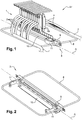
- an electrical plate 1 allowing the connection between them of at least two electrical harnesses 2.
- Plate 1 includes a module holder 3, shown in figure 2 , and various modules 4, 5, 6 capable of being mounted on the module carrier 3, namely a connector module 4, a segregation module 5 and a shutter module 6 respectively, shown in the figures 3 to 5 .
- the electric plates 1 are generally used at the ends of the sections of an airplane to allow the connection and the continuity of the energy transmission circuits, in particular the electric circuits 7.
- the frame 8 in the form of a wire structure forming an interface between the structure of the aircraft and the fixed jaw 9, can be used, for example, when the fixed jaw 9 cannot be fixed with a clamping element. the structure of the aircraft.
- the frame 8 then serves as an interface for fixing one or more jaws 9 fixed on the structure.
- the locking means 11 are cams.
- other means making it possible to keep the movable jaw 10 in the closed position could be used.
- the figure 3 schematically shows a substantially L-shaped groove 12 formed in the fixed jaw 9, this groove 12 being suitable for receiving the different modules 4, 5, 6 as detailed below.
- Plate 1 includes three different types of modules 4, 5, 6, namely a 4 connector module, shown in figure 4 , a segregation module 5, shown in figure 5 , and a shutter module 6 shown in figure 6 .
- the three types of modules 4, 5, 6 have in common a base 13 which engages in the module holder 3 and are differentiated by a part of the module which extends the base 13.
- the base 13 of the modules comprises a body 14 and a pin 15 projecting from the body 14, the pin 15 being received in the portion of shorter length of the L-shaped groove 12 and the body 14 bearing against a vertical surface 16. delimiting the portion of shorter length of L.
- the part of shorter length of the L is of complementary shape to the pin 15.
- the pin 15 is held in the L-shaped groove 12.
- the body 14 is substantially parallelepiped and the pin 15 has a substantially oval shape.
- the pin 15 has a substantially oval shape.
- other particular shapes are possible.
- the connector module 4 comprises a perforated core 17, extending the base 13 and allowing the connection of two harnesses 2 between them, and an umbrella 18 substantially perpendicular to the core 17 and opposite the base 13.
- the umbrella 18 makes it possible to protect the 'core 17, and in particular the connection between two harnesses, of drops of water or of drops of condensation from elements located above the harnesses 2.
- the perforated core 17 of the connector module 4 comprises at least two fixing holes 19 to allow the harnesses 2 to be fixed to each other, on the one hand, and with the connector module 4, on the other hand, for example by means of 20 screw / nut connections.
- the core 17 of the connector modules comprises a window 21 making it possible to make the electrical connection of the two harnesses 2 to one another.
- the 5 segregation modules are similar to the 4 connector modules, except that their core 17 is devoid of fixing holes 19 and window 21.
- the core 17 of the 5 segregation modules is solid instead of being perforated like the core 17 of the 4 connector modules.
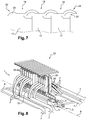
- each connector module 4 and segregation module 5 comprises a first side 22 of greater length having an extra thickness 23 and a second side 24 of greater length, opposite the first, in the form of an open cavity capable of receiving the extra thickness 23 of a connector module 4 or of an adjacent segregation module 5.
- the figure 7 shows the interaction between the umbrellas 18 of several adjacent 4 connector modules or 5 segregation modules.
- closure modules 6 comprise a simple rim 26 extending the base 13 substantially in the direction of extension of the base 13.
- Each of these modules 4, 5, 6 has a specific role.
- the 4 connector modules allow connection between two harnesses 2 while the segregation modules 5 allow separation between two adjacent harnesses 2 of the same circuit 7 or of two separate circuits 7.
- the closure modules 6 provide a filling function intended to prevent the L-shaped groove 12 of the fixed jaw 9 of the module holder 3 from getting dirty.
- the module holder 3 and the modules 4, 5, 6 are made of a thermoplastic material offering a good compromise between mechanical strength and lightness.
- the connecting device 20 is a screw / nut system 20 but it could be lugs which can be clipped into an opposite plug 28 and / or in the 4 connector modules.
- two electrical circuits 7 are connected to the plate 1, the two circuits 7 being separated from each other by a segregation module 5.
- each of the closure modules 6 can, if necessary, be replaced by a module 4 connector or a blanking module 5 so as to increase the connection possibilities of the harnesses 2.
- the devices 20 allow, through the holes 19 for fixing the 4 connector modules, the fixing of the plugs 28 of the harnesses 2 together, but also the fixing of each of the harnesses 2 on the module 4 connector by tightening each of the plugs 28 on 4-connector modules.
- the plate 1 which has just been described offers great modularity for the connection of two harnesses 2 to each other, but also good fixing security since each of the harnesses 2 can be separated from the others by a segregation module 5, in particular to avoid interference between harnesses 2.
- modules 4, 5, 6 that can be engaged between the two jaws 9, 10 of the module holder 3 facilitates the connection or disconnection operations of harness 2 since the modules 4, 5, 6 are interchangeable and that a temporary connection for a repair or for the addition of a new circuit 7 is possible simply and quickly.
- thermoplastic material makes it possible on the one hand to limit the mass of the plate 1 but also to better control the manufacturing tolerances of its constituent elements, so that the assembly of different modules 4, 5 , 6 on the module carrier 3 guarantees good protection of the harnesses 2.
Landscapes
- Engineering & Computer Science (AREA)
- Microelectronics & Electronic Packaging (AREA)
- Connector Housings Or Holding Contact Members (AREA)
- Coupling Device And Connection With Printed Circuit (AREA)
Claims (9)
- Elektrische Platine (1) zum Verbinden von zwei elektrischen Kabelbäumen (2) miteinander, wobei die Platine (1) einen Modulträger (3) und zumindest ein Verbindermodul (4) enthält, um die Verbindung zwischen den beiden elektrischen Kabelbäumen (2) zu ermöglichen, wobei das Verbindermodul (4) einen Sockel (13), der mit dem Modulträger (3) in Eingriff steht, und einen perforierten Kern (17) enthält, der den Sockel (13) fortsetzt und die Verbindung der beiden Kabelbäume (2) miteinander über Stecker (28) ermöglicht,
dadurch gekennzeichnet, dass der Modulträger (3) enthält:- eine ortsfeste Backe (9);- eine bewegliche Backe (10), die zwischen einer Schließposition, in der die bewegliche Backe (10) an der ortsfesten Backe (9) anliegt, und einer Offenposition, in der die bewegliche Backe (10) von der Backe (9) wegbewegt ist, schwenkbar an der ortsfesten Backe (9) angebracht ist, und- Verriegelungsmittel (11), um die bewegliche Backe (10) in Schließposition zu halten, unddass die ortsfeste Backe (9) eine längliche Nut (12) aufweist, die durch lösbaren Eingriff den Sockel von mehreren nebeneinander angeordneten Verbindermodulen (4) in Längsrichtung aufnehmen kann, wobei sich die bewegliche Backe (10) in Schließposition entlang der Nut erstreckt, um dann das oder die darin aufgenommenen Module darin zu sichern. - Platine (1) nach Anspruch 1,
dadurch gekennzeichnet, dass das Verbindermodul (4) eine Abschirmung (18) aufweist, die den Kern (17) abdeckt, um die Verbindung zweier elektrischer Kabelbäume (2) abzuschirmen. - Platine (1) nach Anspruch 1 oder 2,
dadurch gekennzeichnet, dass der Kern (17) des Verbindermoduls (4) zumindest zwei Befestigungslöcher (19) aufweist, um die Befestigung der Stecker (28) jedes Kabelbaums (2) einerseits untereinander und andererseits am Verbindermodul (4) zu gestatten, beispielsweise mittels zumindest einer Verbindungsvorrichtung (20). - Platine (1) nach einem der vorhergehenden Ansprüche,
dadurch gekennzeichnet, dass sie ferner zumindest ein Trennmodul (5) mit einem Sockel (13), einem massiven Kern (17) und einer Abschirmung (18) und/oder zumindest ein Verschlussmodul (6) mit einem Sockel (13) und einem den Sockel (13) fortsetzenden Steg (26) enthält. - Platine (1) nach Anspruch 2 und Anspruch 4,
dadurch gekennzeichnet, dass die Abschirmungen (18) jedes Verbindermoduls (4) und jedes Trennmoduls (5) eine erste Seite (22) mit größerer Länge, die eine Überdicke (23) aufweist, und eine zweite Seite (24) mit größerer Länge, die der ersten gegenüberliegt, in Form eines offenen Hohlraums (25) aufweisen, der die Überdicke (23) eines benachbarten Verbindermoduls (4) oder Trennmoduls (5) aufnehmen kann. - Platine (1) nach einem der vorhergehenden Ansprüche,
dadurch gekennzeichnet, dass der Sockel (13) eines Moduls einen Körper (14) und einen aus dem Körper (14) herausragenden Zapfen (15) enthält. - Platine (1) nach einem der vorhergehenden Ansprüche,
dadurch gekennzeichnet, dass der Modulträger (3) auch einen Rahmen (8) aufweist, an dem die feste Backe (9) angebracht ist. - Platine (1) nach den Ansprüchen 1 und 6,
dadurch gekennzeichnet, dass die Nut (12) im Wesentlichen L-förmig ist und somit einen Schlitz (12a) zur Aufnahme des Körpers (14) aufweist, der von einer quer verlaufenden Aufnahme (12b) zur Aufnahme des Zapfens (15) fortgesetzt wird, wobei der Zapfen (15) jedes Sockels (13) in der Aufnahme (12b) der Nut (12) dann aufgenommen wird, wenn die Nut mehrere Module (4, 5, 6) nebeneinander aufnimmt. - Anordnung (27), enthaltend:- zwei elektrische Kabelbäume (2), die jeweils einen Stecker (28) zur Verbindung der beiden Kabelbäume (2) miteinander aufweisen;- eine Verbindungsplatine (1) nach einem der vorhergehenden Ansprüche, und- zumindest eine Verbindungsvorrichtung (20) zur Befestigung der Stecker (28) der beiden Kabelbäume aneinander.
Applications Claiming Priority (2)
| Application Number | Priority Date | Filing Date | Title |
|---|---|---|---|
| FR1650702A FR3047358B1 (fr) | 2016-01-28 | 2016-01-28 | Platine de connexion de harnais electriques |
| PCT/FR2017/050199 WO2017129925A1 (fr) | 2016-01-28 | 2017-01-27 | Platine de connexion de harnais electriques |
Publications (2)
| Publication Number | Publication Date |
|---|---|
| EP3409084A1 EP3409084A1 (de) | 2018-12-05 |
| EP3409084B1 true EP3409084B1 (de) | 2021-09-08 |
Family
ID=56117836
Family Applications (1)
| Application Number | Title | Priority Date | Filing Date |
|---|---|---|---|
| EP17706586.9A Active EP3409084B1 (de) | 2016-01-28 | 2017-01-27 | Kabelbaumanschlussplatte |
Country Status (5)
| Country | Link |
|---|---|
| US (1) | US10601166B2 (de) |
| EP (1) | EP3409084B1 (de) |
| CN (1) | CN108605421B (de) |
| FR (1) | FR3047358B1 (de) |
| WO (1) | WO2017129925A1 (de) |
Families Citing this family (3)
| Publication number | Priority date | Publication date | Assignee | Title |
|---|---|---|---|---|
| CN108539479A (zh) * | 2018-05-11 | 2018-09-14 | 系新电子技术(苏州)有限公司 | 一种组合式线缆连接装置 |
| FR3091800B1 (fr) * | 2019-01-15 | 2021-05-21 | Safran Electrical & Power | Dispositif de protection pour meuble electrique |
| CN121566253B (zh) * | 2026-01-21 | 2026-04-10 | 徐州奥特润智能科技有限公司 | 汽车线束拧紧设备 |
Family Cites Families (24)
| Publication number | Priority date | Publication date | Assignee | Title |
|---|---|---|---|---|
| US2417369A (en) * | 1944-03-29 | 1947-03-11 | Ibm | Multiple circuit connector of the plug type |
| US3576520A (en) * | 1969-04-11 | 1971-04-27 | Amp Inc | Mounting means for terminal junction modules |
| US3648219A (en) * | 1970-01-15 | 1972-03-07 | Anderson Power Products | Electrical connector mounting rail and disconnecting assembly |
| JPS6210885A (ja) * | 1985-07-08 | 1987-01-19 | 日本航空電子工業株式会社 | コネクタ装置 |
| US5342203A (en) * | 1993-05-25 | 1994-08-30 | United Technologies Corporation | Low profile backshell/wiring integration and interface system |
| JP2962156B2 (ja) * | 1994-08-09 | 1999-10-12 | 住友電装株式会社 | 分割式コネクタ |
| US5643014A (en) * | 1995-05-17 | 1997-07-01 | Lucent Technologies Inc. | Mounting of protectors in connector blocks |
| DE19541936C1 (de) * | 1995-11-10 | 1997-01-09 | Arbo Medizin Technologie Gmbh | Mehrfachsteckeranordnung mit einer Mehrzahl von Einzelsteckern |
| DE19707120C1 (de) * | 1997-02-22 | 1998-06-25 | Harting Kgaa | Halterahmen |
| US6814625B2 (en) * | 2001-04-10 | 2004-11-09 | Cinch Connectors, Inc. | Electrical connector |
| US6685510B1 (en) * | 2002-10-22 | 2004-02-03 | Hon Hai Precision Ind. Co., Ltd. | Electrical cable connector |
| KR100684550B1 (ko) * | 2005-04-04 | 2007-02-20 | 삼성광주전자 주식회사 | 와이어 하네스 고정장치 |
| FR2886504B1 (fr) * | 2005-05-30 | 2007-08-03 | Eurocopter France | Dispositif d'interconnexion reconfigurable de faisceaux electriques |
| US7534958B2 (en) * | 2005-08-03 | 2009-05-19 | Leviton Manufacturing Co., Inc. | Cable retaining system |
| US7352947B2 (en) * | 2005-11-04 | 2008-04-01 | Leviton Manufacturing Co., Inc. | Cable management support system |
| CN101630790A (zh) * | 2008-07-08 | 2010-01-20 | 住友电装株式会社 | 连接器、设置有该连接器的线束以及连接方法 |
| US20100220967A1 (en) * | 2009-02-27 | 2010-09-02 | Cooke Terry L | Hinged Fiber Optic Module Housing and Module |
| GB2480395B (en) * | 2009-03-03 | 2015-03-11 | Commscope Inc | Double hooked reverse mountable module and panel with opening for multiple modules mounting |
| US20110129185A1 (en) * | 2009-11-30 | 2011-06-02 | Lewallen C Paul | Articulated Strain Relief Boot on a Fiber Optic Module and Associated Methods |
| US8287306B2 (en) * | 2010-06-30 | 2012-10-16 | Delphi Technologies, Inc. | Electrical connection system that absorbs multi-connector positional mating tolerance variation |
| US20140014164A1 (en) * | 2012-07-12 | 2014-01-16 | Samsung Sdi Co., Ltd. | Connecting structure of solar cell modules |
| FR2998442B1 (fr) * | 2012-11-22 | 2015-01-23 | Airbus Operations Sas | Platine de coupure pour relier ensemble des harnais de cables electriques sur un aeronef. |
| DE102015216929A1 (de) * | 2015-09-03 | 2017-03-09 | Harting Electric Gmbh & Co. Kg | Halterahmen zur Halterung von Steckverbindermodulen |
| DE102015118263A1 (de) * | 2015-10-27 | 2017-04-27 | Phoenix Contact Gmbh & Co. Kg | Baugruppe eines Steckverbinderteils mit einem Halterahmen zum Aufnehmen von modularen Kontakteinsätzen |
-
2016
- 2016-01-28 FR FR1650702A patent/FR3047358B1/fr not_active Expired - Fee Related
-
2017
- 2017-01-27 EP EP17706586.9A patent/EP3409084B1/de active Active
- 2017-01-27 WO PCT/FR2017/050199 patent/WO2017129925A1/fr not_active Ceased
- 2017-01-27 CN CN201780008987.3A patent/CN108605421B/zh active Active
- 2017-01-27 US US16/073,188 patent/US10601166B2/en active Active
Also Published As
| Publication number | Publication date |
|---|---|
| FR3047358B1 (fr) | 2020-07-17 |
| CN108605421B (zh) | 2021-02-09 |
| WO2017129925A1 (fr) | 2017-08-03 |
| US10601166B2 (en) | 2020-03-24 |
| EP3409084A1 (de) | 2018-12-05 |
| US20190036269A1 (en) | 2019-01-31 |
| FR3047358A1 (fr) | 2017-08-04 |
| CN108605421A (zh) | 2018-09-28 |
Similar Documents
| Publication | Publication Date | Title |
|---|---|---|
| EP0619625B1 (de) | Elektrischer Verbinder mit einer Anzahl von Modulen in Reihen und Kolonnen geordnet | |
| EP3323171B1 (de) | Isolator für eine schwenkbare elektrische verbindung | |
| EP3409084B1 (de) | Kabelbaumanschlussplatte | |
| EP0619626B1 (de) | Elektrischer Verbinder mit einer Anzahl von Steckmodulen | |
| EP3758154B1 (de) | Stromanschlussmodul mit verriegelungs-/entriegelungssystem der stromkabelenden in dem modul, klemmleiste, die eine vielzahl von unabhängigen anschlussmodulen umfasst | |
| EP0784355B1 (de) | Verbindungsanordnung für elektrisches Gerät, insbesondere für ein verbindungsblockartiges Gerät, und ein mit solcher Anordnung ausgerüstetes Gehäuse | |
| EP2214933B1 (de) | Elektrischer anschluss für ein innenmontagelement für ein kraftfahrzeug | |
| EP3544120B1 (de) | Elektrogerät und erdungsverfahren für ein solches gerät | |
| EP3168476B1 (de) | Gehäuse mit einer integrierten kontrollvorrichtung, und elektrischer kompressor, der ein solches gehäuse umfasst | |
| EP3062401B1 (de) | Verbindungssystem für anschluss | |
| EP1912261A1 (de) | Elektrische Anschlussvorrichtung, insbesondere für elektrischen Sonnenkollektor | |
| EP2839546B1 (de) | Schnelles einwegverbindungssystem | |
| EP3788852A1 (de) | Verfahren zum verriegeln/entriegeln eines abnehmbaren moduls und anordnung zur implementierung | |
| EP4207439A1 (de) | Verbindungsvorrichtung, entsprechende anordnung und entsprechendes verbindungsverfahren | |
| EP3815972A1 (de) | Träger- und vrebindungsvorrichtung einer elektronischen karte für die steuerung eines licht- oder signalisierungsmoduls eines kraftfahrzeugs | |
| FR2565302A1 (fr) | Dispositif d'assujettissement provisoire dans l'espace de deux pieces bord a bord | |
| WO2016087462A1 (fr) | Connecteur coaxial integre a un blindage et carte electronique equipee d'un tel connecteur | |
| EP0911932B1 (de) | Montageadapter für nichtquadratisch geformtes elektrisches Apparat | |
| FR3032389A1 (fr) | Dispositif de chauffage electrique | |
| WO2012107387A1 (fr) | Connecteur modulaire et procédé d'assemblage associé | |
| EP4557526B1 (de) | Leistungsanschlussmodul zum klemmen eines elektrischen kabelabschlusses durch ein blatt, dessen mindestens ein verformbares teil zur bildung eines anschlussblockteils einer verbindungsanordnung bildet | |
| FR2938725A1 (fr) | Boitier pour module electronique de controle de machine | |
| FR2746975A1 (fr) | Tableau electrique d'abonne | |
| FR2920598A1 (fr) | Liaison electrique d'une premiere et d'une deuxieme pieces metalliques isolees electriquement l'une par rapport a l'autre | |
| FR2978366A1 (fr) | Ensemble femelle de connexion d'un poste a souder |
Legal Events
| Date | Code | Title | Description |
|---|---|---|---|
| STAA | Information on the status of an ep patent application or granted ep patent |
Free format text: STATUS: UNKNOWN |
|
| STAA | Information on the status of an ep patent application or granted ep patent |
Free format text: STATUS: THE INTERNATIONAL PUBLICATION HAS BEEN MADE |
|
| PUAI | Public reference made under article 153(3) epc to a published international application that has entered the european phase |
Free format text: ORIGINAL CODE: 0009012 |
|
| STAA | Information on the status of an ep patent application or granted ep patent |
Free format text: STATUS: REQUEST FOR EXAMINATION WAS MADE |
|
| 17P | Request for examination filed |
Effective date: 20180808 |
|
| AK | Designated contracting states |
Kind code of ref document: A1 Designated state(s): AL AT BE BG CH CY CZ DE DK EE ES FI FR GB GR HR HU IE IS IT LI LT LU LV MC MK MT NL NO PL PT RO RS SE SI SK SM TR |
|
| AX | Request for extension of the european patent |
Extension state: BA ME |
|
| DAV | Request for validation of the european patent (deleted) | ||
| DAX | Request for extension of the european patent (deleted) | ||
| STAA | Information on the status of an ep patent application or granted ep patent |
Free format text: STATUS: EXAMINATION IS IN PROGRESS |
|
| 17Q | First examination report despatched |
Effective date: 20190807 |
|
| GRAP | Despatch of communication of intention to grant a patent |
Free format text: ORIGINAL CODE: EPIDOSNIGR1 |
|
| STAA | Information on the status of an ep patent application or granted ep patent |
Free format text: STATUS: GRANT OF PATENT IS INTENDED |
|
| INTG | Intention to grant announced |
Effective date: 20210519 |
|
| RIN1 | Information on inventor provided before grant (corrected) |
Inventor name: COLIN, FREDERIC Inventor name: TCHAAOUAOU, ISMAIL |
|
| GRAS | Grant fee paid |
Free format text: ORIGINAL CODE: EPIDOSNIGR3 |
|
| GRAA | (expected) grant |
Free format text: ORIGINAL CODE: 0009210 |
|
| STAA | Information on the status of an ep patent application or granted ep patent |
Free format text: STATUS: THE PATENT HAS BEEN GRANTED |
|
| AK | Designated contracting states |
Kind code of ref document: B1 Designated state(s): AL AT BE BG CH CY CZ DE DK EE ES FI FR GB GR HR HU IE IS IT LI LT LU LV MC MK MT NL NO PL PT RO RS SE SI SK SM TR |
|
| REG | Reference to a national code |
Ref country code: GB Ref legal event code: FG4D Free format text: NOT ENGLISH |
|
| REG | Reference to a national code |
Ref country code: AT Ref legal event code: REF Ref document number: 1429767 Country of ref document: AT Kind code of ref document: T Effective date: 20210915 Ref country code: CH Ref legal event code: EP |
|
| REG | Reference to a national code |
Ref country code: IE Ref legal event code: FG4D Free format text: LANGUAGE OF EP DOCUMENT: FRENCH |
|
| REG | Reference to a national code |
Ref country code: DE Ref legal event code: R096 Ref document number: 602017045622 Country of ref document: DE |
|
| REG | Reference to a national code |
Ref country code: LT Ref legal event code: MG9D |
|
| REG | Reference to a national code |
Ref country code: NL Ref legal event code: MP Effective date: 20210908 |
|
| PG25 | Lapsed in a contracting state [announced via postgrant information from national office to epo] |
Ref country code: BG Free format text: LAPSE BECAUSE OF FAILURE TO SUBMIT A TRANSLATION OF THE DESCRIPTION OR TO PAY THE FEE WITHIN THE PRESCRIBED TIME-LIMIT Effective date: 20211208 Ref country code: LT Free format text: LAPSE BECAUSE OF FAILURE TO SUBMIT A TRANSLATION OF THE DESCRIPTION OR TO PAY THE FEE WITHIN THE PRESCRIBED TIME-LIMIT Effective date: 20210908 Ref country code: ES Free format text: LAPSE BECAUSE OF FAILURE TO SUBMIT A TRANSLATION OF THE DESCRIPTION OR TO PAY THE FEE WITHIN THE PRESCRIBED TIME-LIMIT Effective date: 20210908 Ref country code: FI Free format text: LAPSE BECAUSE OF FAILURE TO SUBMIT A TRANSLATION OF THE DESCRIPTION OR TO PAY THE FEE WITHIN THE PRESCRIBED TIME-LIMIT Effective date: 20210908 Ref country code: NO Free format text: LAPSE BECAUSE OF FAILURE TO SUBMIT A TRANSLATION OF THE DESCRIPTION OR TO PAY THE FEE WITHIN THE PRESCRIBED TIME-LIMIT Effective date: 20211208 Ref country code: RS Free format text: LAPSE BECAUSE OF FAILURE TO SUBMIT A TRANSLATION OF THE DESCRIPTION OR TO PAY THE FEE WITHIN THE PRESCRIBED TIME-LIMIT Effective date: 20210908 Ref country code: SE Free format text: LAPSE BECAUSE OF FAILURE TO SUBMIT A TRANSLATION OF THE DESCRIPTION OR TO PAY THE FEE WITHIN THE PRESCRIBED TIME-LIMIT Effective date: 20210908 Ref country code: HR Free format text: LAPSE BECAUSE OF FAILURE TO SUBMIT A TRANSLATION OF THE DESCRIPTION OR TO PAY THE FEE WITHIN THE PRESCRIBED TIME-LIMIT Effective date: 20210908 |
|
| REG | Reference to a national code |
Ref country code: AT Ref legal event code: MK05 Ref document number: 1429767 Country of ref document: AT Kind code of ref document: T Effective date: 20210908 |
|
| PG25 | Lapsed in a contracting state [announced via postgrant information from national office to epo] |
Ref country code: LV Free format text: LAPSE BECAUSE OF FAILURE TO SUBMIT A TRANSLATION OF THE DESCRIPTION OR TO PAY THE FEE WITHIN THE PRESCRIBED TIME-LIMIT Effective date: 20210908 Ref country code: GR Free format text: LAPSE BECAUSE OF FAILURE TO SUBMIT A TRANSLATION OF THE DESCRIPTION OR TO PAY THE FEE WITHIN THE PRESCRIBED TIME-LIMIT Effective date: 20211209 |
|
| PG25 | Lapsed in a contracting state [announced via postgrant information from national office to epo] |
Ref country code: AT Free format text: LAPSE BECAUSE OF FAILURE TO SUBMIT A TRANSLATION OF THE DESCRIPTION OR TO PAY THE FEE WITHIN THE PRESCRIBED TIME-LIMIT Effective date: 20210908 |
|
| PGFP | Annual fee paid to national office [announced via postgrant information from national office to epo] |
Ref country code: DE Payment date: 20211215 Year of fee payment: 6 |
|
| PG25 | Lapsed in a contracting state [announced via postgrant information from national office to epo] |
Ref country code: IS Free format text: LAPSE BECAUSE OF FAILURE TO SUBMIT A TRANSLATION OF THE DESCRIPTION OR TO PAY THE FEE WITHIN THE PRESCRIBED TIME-LIMIT Effective date: 20220108 Ref country code: SM Free format text: LAPSE BECAUSE OF FAILURE TO SUBMIT A TRANSLATION OF THE DESCRIPTION OR TO PAY THE FEE WITHIN THE PRESCRIBED TIME-LIMIT Effective date: 20210908 Ref country code: SK Free format text: LAPSE BECAUSE OF FAILURE TO SUBMIT A TRANSLATION OF THE DESCRIPTION OR TO PAY THE FEE WITHIN THE PRESCRIBED TIME-LIMIT Effective date: 20210908 Ref country code: RO Free format text: LAPSE BECAUSE OF FAILURE TO SUBMIT A TRANSLATION OF THE DESCRIPTION OR TO PAY THE FEE WITHIN THE PRESCRIBED TIME-LIMIT Effective date: 20210908 Ref country code: PT Free format text: LAPSE BECAUSE OF FAILURE TO SUBMIT A TRANSLATION OF THE DESCRIPTION OR TO PAY THE FEE WITHIN THE PRESCRIBED TIME-LIMIT Effective date: 20220110 Ref country code: PL Free format text: LAPSE BECAUSE OF FAILURE TO SUBMIT A TRANSLATION OF THE DESCRIPTION OR TO PAY THE FEE WITHIN THE PRESCRIBED TIME-LIMIT Effective date: 20210908 Ref country code: NL Free format text: LAPSE BECAUSE OF FAILURE TO SUBMIT A TRANSLATION OF THE DESCRIPTION OR TO PAY THE FEE WITHIN THE PRESCRIBED TIME-LIMIT Effective date: 20210908 Ref country code: EE Free format text: LAPSE BECAUSE OF FAILURE TO SUBMIT A TRANSLATION OF THE DESCRIPTION OR TO PAY THE FEE WITHIN THE PRESCRIBED TIME-LIMIT Effective date: 20210908 Ref country code: CZ Free format text: LAPSE BECAUSE OF FAILURE TO SUBMIT A TRANSLATION OF THE DESCRIPTION OR TO PAY THE FEE WITHIN THE PRESCRIBED TIME-LIMIT Effective date: 20210908 Ref country code: AL Free format text: LAPSE BECAUSE OF FAILURE TO SUBMIT A TRANSLATION OF THE DESCRIPTION OR TO PAY THE FEE WITHIN THE PRESCRIBED TIME-LIMIT Effective date: 20210908 |
|
| REG | Reference to a national code |
Ref country code: DE Ref legal event code: R097 Ref document number: 602017045622 Country of ref document: DE |
|
| PLBE | No opposition filed within time limit |
Free format text: ORIGINAL CODE: 0009261 |
|
| STAA | Information on the status of an ep patent application or granted ep patent |
Free format text: STATUS: NO OPPOSITION FILED WITHIN TIME LIMIT |
|
| PG25 | Lapsed in a contracting state [announced via postgrant information from national office to epo] |
Ref country code: DK Free format text: LAPSE BECAUSE OF FAILURE TO SUBMIT A TRANSLATION OF THE DESCRIPTION OR TO PAY THE FEE WITHIN THE PRESCRIBED TIME-LIMIT Effective date: 20210908 |
|
| 26N | No opposition filed |
Effective date: 20220609 |
|
| PG25 | Lapsed in a contracting state [announced via postgrant information from national office to epo] |
Ref country code: SI Free format text: LAPSE BECAUSE OF FAILURE TO SUBMIT A TRANSLATION OF THE DESCRIPTION OR TO PAY THE FEE WITHIN THE PRESCRIBED TIME-LIMIT Effective date: 20210908 Ref country code: MC Free format text: LAPSE BECAUSE OF FAILURE TO SUBMIT A TRANSLATION OF THE DESCRIPTION OR TO PAY THE FEE WITHIN THE PRESCRIBED TIME-LIMIT Effective date: 20210908 |
|
| REG | Reference to a national code |
Ref country code: CH Ref legal event code: PL |
|
| REG | Reference to a national code |
Ref country code: BE Ref legal event code: MM Effective date: 20220131 |
|
| PG25 | Lapsed in a contracting state [announced via postgrant information from national office to epo] |
Ref country code: LU Free format text: LAPSE BECAUSE OF NON-PAYMENT OF DUE FEES Effective date: 20220127 |
|
| PG25 | Lapsed in a contracting state [announced via postgrant information from national office to epo] |
Ref country code: BE Free format text: LAPSE BECAUSE OF NON-PAYMENT OF DUE FEES Effective date: 20220131 |
|
| PG25 | Lapsed in a contracting state [announced via postgrant information from national office to epo] |
Ref country code: LI Free format text: LAPSE BECAUSE OF NON-PAYMENT OF DUE FEES Effective date: 20220131 Ref country code: CH Free format text: LAPSE BECAUSE OF NON-PAYMENT OF DUE FEES Effective date: 20220131 |
|
| PG25 | Lapsed in a contracting state [announced via postgrant information from national office to epo] |
Ref country code: IT Free format text: LAPSE BECAUSE OF FAILURE TO SUBMIT A TRANSLATION OF THE DESCRIPTION OR TO PAY THE FEE WITHIN THE PRESCRIBED TIME-LIMIT Effective date: 20210908 Ref country code: IE Free format text: LAPSE BECAUSE OF NON-PAYMENT OF DUE FEES Effective date: 20220127 |
|
| REG | Reference to a national code |
Ref country code: DE Ref legal event code: R119 Ref document number: 602017045622 Country of ref document: DE |
|
| PG25 | Lapsed in a contracting state [announced via postgrant information from national office to epo] |
Ref country code: DE Free format text: LAPSE BECAUSE OF NON-PAYMENT OF DUE FEES Effective date: 20230801 |
|
| PG25 | Lapsed in a contracting state [announced via postgrant information from national office to epo] |
Ref country code: HU Free format text: LAPSE BECAUSE OF FAILURE TO SUBMIT A TRANSLATION OF THE DESCRIPTION OR TO PAY THE FEE WITHIN THE PRESCRIBED TIME-LIMIT; INVALID AB INITIO Effective date: 20170127 |
|
| PG25 | Lapsed in a contracting state [announced via postgrant information from national office to epo] |
Ref country code: MK Free format text: LAPSE BECAUSE OF FAILURE TO SUBMIT A TRANSLATION OF THE DESCRIPTION OR TO PAY THE FEE WITHIN THE PRESCRIBED TIME-LIMIT Effective date: 20210908 Ref country code: CY Free format text: LAPSE BECAUSE OF FAILURE TO SUBMIT A TRANSLATION OF THE DESCRIPTION OR TO PAY THE FEE WITHIN THE PRESCRIBED TIME-LIMIT Effective date: 20210908 |
|
| PG25 | Lapsed in a contracting state [announced via postgrant information from national office to epo] |
Ref country code: MT Free format text: LAPSE BECAUSE OF FAILURE TO SUBMIT A TRANSLATION OF THE DESCRIPTION OR TO PAY THE FEE WITHIN THE PRESCRIBED TIME-LIMIT Effective date: 20210908 |
|
| PG25 | Lapsed in a contracting state [announced via postgrant information from national office to epo] |
Ref country code: TR Free format text: LAPSE BECAUSE OF FAILURE TO SUBMIT A TRANSLATION OF THE DESCRIPTION OR TO PAY THE FEE WITHIN THE PRESCRIBED TIME-LIMIT Effective date: 20210908 |
|
| PGFP | Annual fee paid to national office [announced via postgrant information from national office to epo] |
Ref country code: GB Payment date: 20260122 Year of fee payment: 10 |
|
| PGFP | Annual fee paid to national office [announced via postgrant information from national office to epo] |
Ref country code: FR Payment date: 20260121 Year of fee payment: 10 |