EP3409168B1 - Module de nettoyage d'angle pour robots de nettoyage modulaires - Google Patents
Module de nettoyage d'angle pour robots de nettoyage modulaires Download PDFInfo
- Publication number
- EP3409168B1 EP3409168B1 EP18172808.0A EP18172808A EP3409168B1 EP 3409168 B1 EP3409168 B1 EP 3409168B1 EP 18172808 A EP18172808 A EP 18172808A EP 3409168 B1 EP3409168 B1 EP 3409168B1
- Authority
- EP
- European Patent Office
- Prior art keywords
- robot
- cleaning
- unit
- robot unit
- cleaning module
- Prior art date
- Legal status (The legal status is an assumption and is not a legal conclusion. Google has not performed a legal analysis and makes no representation as to the accuracy of the status listed.)
- Active
Links
Images



Classifications
-
- A—HUMAN NECESSITIES
- A47—FURNITURE; DOMESTIC ARTICLES OR APPLIANCES; COFFEE MILLS; SPICE MILLS; SUCTION CLEANERS IN GENERAL
- A47L—DOMESTIC WASHING OR CLEANING; SUCTION CLEANERS IN GENERAL
- A47L9/00—Details or accessories of suction cleaners, e.g. mechanical means for controlling the suction or for effecting pulsating action; Storing devices specially adapted to suction cleaners or parts thereof; Carrying-vehicles specially adapted for suction cleaners
- A47L9/02—Nozzles
- A47L9/04—Nozzles with driven brushes or agitators
- A47L9/0461—Dust-loosening tools, e.g. agitators, brushes
- A47L9/0488—Combinations or arrangements of several tools, e.g. edge cleaning tools
-
- A—HUMAN NECESSITIES
- A47—FURNITURE; DOMESTIC ARTICLES OR APPLIANCES; COFFEE MILLS; SPICE MILLS; SUCTION CLEANERS IN GENERAL
- A47L—DOMESTIC WASHING OR CLEANING; SUCTION CLEANERS IN GENERAL
- A47L2201/00—Robotic cleaning machines, i.e. with automatic control of the travelling movement or the cleaning operation
Definitions
- the invention relates to a corner cleaning module and a modular cleaning robot with a robot unit and a corner cleaning module.
- the German publication DE 10 2007 036 163 A1 describes a method and a device for determining a driving pattern of a floor care device, in particular a dust collection robot.
- the size of the room or the delimited area is determined qualitatively or quantitatively.
- Different driving patterns are carried out for driving the floor care device or dust collecting robot in rooms or delimited areas of different sizes.
- German publication DE 10 2005 046 813 A1 describes a method for operating an automatically movable household appliance, such as a floor dust collecting device, in one room or in a plurality of rooms. It is proposed that, if necessary, station elements are arranged in addition to a base station, which emit signals that indicate the respective location of the station element, and that the household appliance orients itself in the room by processing these signals. In this way it is achieved that a self-sufficient soil dust collecting device can be operated reliably in one room or in a plurality of rooms.
- a handheld vacuum cleaner which has an upright section and a base with a nozzle and also an edge cleaner.
- the edge cleaner includes a body and brushes.
- the edge cleaner is rotatably attached to the base of the vacuum cleaner and preferably comprises a vacuum connection.
- the edge cleaner has an operating position in which the edge cleaner rests on the floor, as well as a stowed position in which the brushes are lifted off the floor and the vacuum connection is separated from the vacuum suction.
- the European patent application EP 2 783 617 A1 describes a self-propelled vacuum cleaner, which comprises a mobile unit and a suction device.
- the mobile unit has a housing and a control module.
- the suction device is detachably attached to the mobile unit and has a suction module and a filter module.
- the U.S. patent application US 2005/0 209 736 A1 describes a self-propelled work robot that includes a drive assembly with a wheel and first and second work assemblies that are removable from the drive assembly.
- One of the first and second work arrangements is selectively attached to the driving arrangement.
- the second working arrangement can be, for example, a suction and cleaning arrangement which can be attached to the driving arrangement.
- the driving assembly includes a drive motor that drives the wheel, a wheel control device that controls the rotation of the drive motor, a discriminator that detects which of the work assemblies is mounted, and a work signal output device that, in response to a result of a discrimination, a work signal for operating the work assembly outputs.
- the German patent application DE 101 39 213 A1 describes a dust cleaning attachment for a vacuum cleaner with a suction line.
- a skirting board brush which is also connected to the suction line, is held on the edge of the suction cleaning attachment with respect to the direction of travel.
- the suction line connection of the baseboard brush can be changed between an open and a closed position.
- the Japanese patent application JP 2013-233 305 A describes a self-propelled vacuum cleaner that is able to clean a baseboard or a wall surface.
- the self-propelled vacuum cleaner includes drive wheels, a body that moves on a surface to be cleaned by means of the drive wheels, and a baseboard brush unit provided on one side of the body to clean the upper surface of a baseboard.
- the U.S. patent application US 2007/0 113 373 A1 describes a vacuum cleaner provided with a left cover and a right cover covering a suction port body so that they are movable in the right and left directions to facilitate cleaning by expanding the suction port body when the side of a wall, a Corner of a room and the like can be cleaned.
- the right cover moves so that it protrudes outward from a bumper.
- a part of the suction port body expands to the side, and an expansion space covered by the right cover is formed on the right side of the suction port body. Dust and dirt on a floor surface facing this room are sucked in through a main suction opening.
- side suction openings made of a flexible material are communicated in both end portions to the right and left of a dust suction chamber of the suction port body, so that dust and dirt are also sucked through the side suction opening when the side of the wall is cleaned.
- the U.S. patent application US 2011/0 153 081 A1 describes a robot cleaner that includes a cleaning unit for cleaning a surface and a main robot body.
- the main robot body contains a drive system to generate movement of the robot cleaner and a microcontroller to control the movement of the Robot cleaner.
- the cleaning unit is arranged in front of the drive system and the width of the cleaning unit is larger than the width of the main robot body.
- a robot cleaning system comprises a main robot body and several cleaning units for cleaning a surface.
- the main robot body contains a drive system to generate movement of the robot cleaner and a microcontroller to control the movement of the robot cleaner.
- the cleaning arrangement is arranged in front of the drive system, each of the cleaning arrangements is removable from the main robot body and each of the cleaning arrangements has a unique cleaning function.
- the U.S. patent US 5 720 077 A describes a driving robot for executing predetermined operations using a processing unit and a processing method using a driving robot.
- a chassis unit is rotatably attached to an attachment part and a processing unit is movably attached to the attachment part. Therefore, an operation can be carried out efficiently within a large area, even in a corner portion, and a desired work can be performed even in a restricted area by moving the processing unit into a working area and operating the processing unit directly in the restricted area.
- the task is solved by providing a corner cleaning module that has a suction mouth for vacuuming a suction area and has a blower unit which is designed to generate a suction air flow, the flow path for the suction air flow extending to the suction mouth.
- the corner cleaning module has a mechanical interface with which a detachable mechanical connection can be formed between the corner cleaning module and a robot unit.
- the suction mouth is arranged on the corner cleaning module in such a way that when the corner cleaning module is coupled to the robot unit, the suction mouth protrudes beyond an outer contour of the robot unit to such an extent that a suction area outside the outer contour of the robot unit can be extracted through the suction mouth.
- the suction area of the suction mouth is outside the outer contour of the robot unit.
- the corner cleaning module When the corner cleaning module is coupled to the robot unit, the corner cleaning module protrudes laterally beyond the outer contour of the robot unit when viewed in the forward direction of travel of the robot unit, and the suction mouth is arranged laterally from the robot unit when viewed in the forward direction of travel of the robot unit.
- the corner cleaning module has an energy interface, via which the corner cleaning module can be supplied with energy from the robot unit.
- the corner cleaning module is specially designed to vacuum difficult-to-reach corners and edges of a surface or a room to be cleaned.
- the corner cleaning module comprises a suction mouth and a blower unit, which generates a suction air flow for extracting dirt and dust.
- the corner cleaning module is designed to be connected to a robot unit via a mechanical interface.
- the robot unit is designed, for example, as a mobile robot unit with which the cleaning module can be moved relative to the surface to be cleaned.
- the suction mouth is attached to the corner cleaning module in such a way that when the corner cleaning module is coupled to the robot unit, it is located outside the outer contour of the robot unit.
- the suction mouth is attached to the corner cleaning module in such a way that when the corner cleaning module is coupled to the robot unit, it is located outside the outer contour of the robot unit.
- a cleaning robot has a modular structure and comprises a robot unit and a corner cleaning module.
- the corner cleaning module has a suction mouth for sucking off a suction area and a blower unit which is designed to generate a suction air flow, the flow path for the suction air flow extending to the suction mouth.
- the corner cleaning module has a mechanical interface via which the corner cleaning module is connected to the robot unit in a releasable mechanical connection.
- the suction mouth is arranged on the corner cleaning module in such a way that the suction mouth protrudes beyond the outer contour of the robot unit to such an extent that a suction area outside the outer contour of the robot unit can be extracted through the suction mouth.
- the suction area of the suction mouth is outside the outer contour of the robot unit.
- the corner cleaning module viewed in the forward direction of the robot unit, projects laterally beyond the outer contour of the robot unit, the suction mouth being arranged laterally from the robot unit, viewed in the forward direction of the robot unit.
- the corner cleaning module has an energy interface, via which the corner cleaning module can be supplied with energy from the robot unit.
- the robot unit comprises a chassis with a drive unit and a control unit.
- different cleaning modules can be placed on one robot unit.
- a further module for the extensive suction of surfaces or a module for wet wiping of surfaces It is not necessary to equip each of the cleaning modules separately with a chassis, a drive and a control.
- the use of a modular cleaning robot is particularly advantageous for corner cleaning because this cleaning step must be carried out in addition to the actual surface cleaning.
- the robot unit with the undercarriage and the control can thus be used together for all cleaning modules each required cleaning module is placed on the robot unit and mechanically detachably attached via the mechanical interface.
- the suction mouth is attached to the corner cleaning module in such a way that when the corner cleaning module is coupled to the robot unit, it is located outside the outer contour of the robot unit.
- the upstream positioning of the suction mouth outside the outer contour of the robot unit enables cleaning of hard-to-reach places that the robot unit itself cannot approach.
- the concept of a cleaning agent arranged outside the outer contour is unconventional, because the outer contour of the cleaning robot is generally used to detect collisions. It is therefore a qualitatively new approach to arrange cleaning agents outside the outer contour, which is protected against collisions.
- a cleaning robot is a cleaning device that is able to move automatically relative to a surface to be cleaned or to an object to be cleaned and to completely or partially clean the surface or the object.
- the cleaning robot is equipped with one or more cleaning devices.
- the cleaning robot can be equipped with stationary or driven brushes, rollers, wipers, cloths or other cleaning devices.
- the cleaning robot can comprise a vacuum cleaner, for example a wet vacuum cleaner or a dry vacuum cleaner or a combined wet / dry vacuum cleaner.
- a cleaning robot is usually equipped with a trolley.
- the undercarriage can be controlled, for example, by a controller that can be present in the cleaning robot or outside the cleaning robot.
- the control uses, for example, data to control the undercarriage, which are provided by one or more sensors, which, at least in part, can be present in the cleaning robot or outside the cleaning robot.
- Typical sensors include a mechanical collision sensor, a camera, an ultrasonic sensor, an infrared sensor, a distance sensor, an acceleration sensor and a compass.
- a cleaning robot can comprise one or more mapping means or have a functional connection therewith.
- Mapping means include, in particular, devices for recording, storing or evaluating geometric properties of the room in which the cleaning robot works or is intended to work. The mapping means can advantageously contribute to a planned navigation of the cleaning robot in the room.
- Rooms can be exterior or interior spaces, e.g. B. interiors of buildings such as living quarters or household rooms.
- a cleaning robot is usually battery operated. So that the battery of such a cleaning robot can be recharged after a cleaning phase, a charging station separate from the cleaning robot can be provided.
- the cleaning robot can be designed in such a way that it automatically starts the charging station to charge the battery and / or connects itself to the charging station independently.
- a cleaning robot can comprise, for example, a vacuum cleaner, wherein the vacuum cleaner can be designed as a wet vacuum cleaner, as a dry vacuum cleaner or as a combined wet / dry vacuum cleaner.
- the cleaning robot can comprise a wet vacuum cleaner and can be designed to apply liquid to a surface to be cleaned or to an object to be cleaned and to vacuum the liquid again by means of the wet vacuum cleaner.
- the cleaning robot can comprise further cleaning devices such as brushes, rollers, wipers, cloths or other cleaning devices. The cleaning effect of the vacuum cleaner is preferably supported by these additional cleaning devices.
- a vacuum cleaner in the sense of the present invention is a device that can generate a suction air flow that acts on an object, usually a surface, for example a floor surface, to remove particles such as dirt or dust particles, but also liquids, for example, from the object to be recorded by being picked up by the suction air flow and entrained (hereinafter also referred to as “suction”).
- a vacuum cleaner can advantageously achieve a cleaning effect in this way.
- the vacuum cleaner is generally equipped with a suction fan for generating a suction air flow, a suction opening of the vacuum cleaner being in flow connection with the suction side of the suction fan.
- the suction opening is typically designed so that it over the object to be cleaned, for. B. a floor surface can be guided to the particles, for. B. dust or dirt.
- the suction fan is usually in flow connection with at least one dust separating device, for example a, usually exchangeable, dust filter bag, a filter device or a centrifugal separator. Dirt particles absorbed by the suction air flow are generally collected in a dust collection room, with a vacuum cleaner with a dust filter bag usually having the dust filter in the dust collection room.
- Cleaning robots that are equipped with a vacuum cleaner generally collect dirt and dust in a dust collector arranged in the cleaning robot.
- the space available on the cleaning robot is usually limited, so that the space provided for the dust collector is also limited.
- the cleaning robot can be designed in such a way that it automatically drives to the dust collecting station to discharge the dust and / or connects itself to the dust collecting station independently.
- the dust collecting station can be designed as a dust collecting station connected to a charging station or as a dust collecting station separated from a charging station.
- the corner cleaning module is preferably designed to clean corners and edges of a surface or a room to be cleaned.
- corner and edge areas are often not correctly detected by the suction nozzle of a cleaning robot because the suction nozzle cannot penetrate the corners and edges.
- the corner cleaning module is specially designed for cleaning these hard-to-reach areas.
- the suction mouth of the corner cleaning module can be shaped and dimensioned such that cleaning of corner and edge areas is made possible.
- the corner cleaning module can be placed on a mobile robot unit and can selectively move and clean the corner and edge areas in one corner and edge cleaning step.
- the robot unit is preferably designed to move automatically relative to a surface to be cleaned or in a room to be cleaned.
- the robot unit is able to automatically navigate in the room and create routes for the cleaning run, which are then converted into corresponding control commands for driving the robot unit. This enables automatic cleaning of surfaces or rooms.
- the robot unit comprises a chassis with a drive unit and a control unit.
- the control unit can be used, for example, to generate control commands which are directed to the drive unit and control the movement of the robot unit.
- the corner cleaning module is preferably attached to the robot unit in a predefined position. This results in a defined relative position between the robot unit and the corner cleaning module. As a result of this predetermined arrangement of the corner cleaning module on the robot unit, the robot unit can navigate the corner cleaning module exactly to the desired positions.
- the corner cleaning module can preferably be connected to the robot unit so that it cannot move or rotate, via the mechanical interface. This ensures a stable mechanical fixation of the corner cleaning module on the robot unit. In particular, this allows precise movement control for the suction mouth attached to the corner cleaning module.
- the corner cleaning module can preferably be positively connected to the robot unit via the mechanical interface. Further preferably, the corner cleaning module can be locked to the robot unit by means of at least one locking element. A detachable mechanical connection between the cleaning module used in each case and the robot unit is established via the mechanical interface. This releasable mechanical connection can additionally be locked by at least one locking element. In this case, it is necessary to release the lock before the respective cleaning module, in particular the corner cleaning module, can be removed from the robot unit.
- the corner cleaning module is preferably designed as an independent vacuum cleaner device.
- the blower unit and the flow path for the suction air flow are arranged on the corner cleaning module itself. It is therefore not necessary to guide the suction air flow from the corner cleaning module to the robot unit. No interface for the suction air flow is required between the robot unit and the corner cleaning module.
- the corner cleaning module preferably has a data interface which is designed to enable an exchange of at least one of data and control commands between the corner cleaning module and the robot unit.
- Control commands for example, can be transmitted from the control unit arranged in the robot unit to components of the corner cleaning module via the data interface.
- sensor signals from sensors which are arranged on the side of the corner cleaning module can be transmitted to the robot unit via the data interface. In this way, the sensor signals detected by the respective cleaning module can also be taken into account when determining the travel routes.
- the corner cleaning module has an energy interface, via which the corner cleaning module can be supplied with energy from the robot unit.
- an accumulator is provided in the robot unit, which supplies the robot unit with current.
- the required power can be made available to the corner cleaning module from the robot unit via the energy interface. In this case, it is not necessary to provide a separate battery on the corner cleaning module side.
- the suction area of the suction mouth is outside the outer contour of the robot unit.
- the corner cleaning module with the suction mouth attached to it is designed such that it extends beyond the outer contour of the robot unit, so that the suction mouth comprises a suction area outside the outer contour of the suction robot. By placing the suction area outside the outer contour, it can be achieved that the suction mouth can penetrate into corner and edge areas that are not accessible to the robot unit, which is generally somewhat larger.
- the corner cleaning module preferably comprises a base unit and a side support element, on which the suction mouth is arranged at a distance from the base unit. It can be achieved by the carrier element that the suction mouth is attached sufficiently far outside on the corner cleaning module so that a suction area outside the outer contour of the robot unit can be grasped by the suction mouth.
- the suction mouth is preferably arranged in the vicinity of one of the front corners of the robot unit.
- the corner cleaning module viewed in the forward direction of the robot unit, projects laterally beyond the outer contour of the robot unit.
- the suction mouth is arranged to the side of the robot unit when viewed in the forward direction of travel of the robot unit.
- the suction mouth is preferably arranged outside the outer contour of the robot unit and to the side of the robot unit.
- the suction mouth is preferably located completely outside the outer contour of the robot unit.
- the robot unit is widened by the corner cleaning module and the suction mouth, for example in the direction laterally to the forward driving direction, in order to be able to carry out corner and edge cleaning in the lateral edge region of the robot unit.
- the corner and edge areas can be extracted through the suction mouth.
- the suction mouth When viewed in the forward direction of the robot unit, the suction mouth preferably closes at the front end of the robot unit essentially flush with the robot unit.
- the shape and dimensions of the suction mouth are preferably designed to clean the corners and edges of a surface or a space to be cleaned. In order to be able to clean these places that are difficult to access, it is necessary, for example, to appropriately dimension the suction opening of the suction mouth. As a rule, the suction opening for corner and edge cleaning will be made smaller than would be the case with a suction mouth provided for surface cleaning.
- the area of the suction opening of the suction mouth is preferably significantly smaller than the area of the robot unit when projected perpendicularly onto the floor level.
- the suction opening of the suction mouth preferably has an area of at least one fortieth of the area of the robot unit when projected perpendicularly onto the floor level, more preferably of at least one thirtieth of the area of the robot unit, further preferably of at least one twenty-fifth of the area of the robot unit.
- the suction opening of the suction mouth preferably has an area of at most one fifth of the area of the robot unit when projected onto the floor plane, more preferably an area of at most one tenth of the area of the robot unit, further preferably an area of at most one fifteenth of the area of the robot unit.
- the geometric shape of the suction surface For example, designed so that dust and dirt in the corner and edge areas are extracted as completely as possible.
- the shape and dimensioning of the suction mouth are preferably designed to be able to penetrate as far as possible into a corner or edge to be cleaned.
- a suction opening of the suction mouth preferably has one of the following shapes: circular, oval, triangular, square, square, rectangular, polygonal.
- the suction mouth preferably widens from top to bottom in the direction of the surface to be cleaned. Such a conical widening of the suction mouth from top to bottom, for example, enables the dust to be completely sucked up to the edge.
- the suction mouth preferably consists entirely or partially of an elastomer.
- Elastomers are characterized by the fact that they deform when force is applied, but that they return to their original shape after the force is removed.
- the suction mouth is preferably made entirely or partially of rubber or silicone.
- Additional cleaning agents are preferably attached to the suction mouth or in the suction mouth.
- At least one rotatable brush is preferably provided on the suction mouth or in the suction mouth.
- a rotating brush the axis of which can be oriented, for example, horizontally, at an angle or perpendicular to the surface to be cleaned, conveys the dirt from a larger intake area to the suction mouth. This allows dust and dirt to be captured better.
- adhering dirt can also be loosened and vacuumed.
- Bristles or other at least partially sealing elements are preferably attached to the suction mouth.
- the bristles at least partially seal the suction mouth from the surface to be suctioned off, so that the suction effect is improved.
- the suction mouth is preferably equipped with at least one sensor.
- the at least one sensor preferably comprises at least one of the following: a distance-sensitive element, an electrical distance sensor, an optical distance sensor, a collision sensor.
- the distance to the wall or to another object can be determined using the at least one sensor.
- the sensor signals can, for example, be supplied to the central control unit on the side of the robot unit via the data interface and be taken into account there when determining the travel path, so that a collision with the wall or with other objects can be avoided in this way.
- the at least one sensor can also include a collision sensor which, when mechanically touching the wall or another object, outputs a signal which in turn is transmitted to the robot unit and is taken into account there when controlling the drive.
- the suction mouth is arranged outside the outer contour of the robot unit, collisions with the wall or with other objects can either be completely avoided or can be immediately recognized and taken into account in the movement control.
- the suction mouth is preferably equipped with a bumper which is designed to dampen collisions with other objects.
- the corner cleaning module preferably comprises a dust separation device for cleaning the suction air flow, which is arranged in the flow path of the suction air flow.
- the dust separation device can comprise, for example, a dust collection space. The suction air flow is cleaned on the side of the corner cleaning module so that a cleaned exhaust air is released into the environment.
- the corner cleaning module preferably comprises at least one filter device for cleaning the suction air flow, which is arranged in the flow path of the suction air flow.
- the air in the suction air stream is further cleaned by the at least one filter arrangement.
- a fine dust filter can be provided in the flow path.
- the flow path of the suction air stream preferably extends from the suction mouth via a dust separation device and the blower unit to at least one outlet opening.
- the complete flow path from the suction mouth to at least one outlet opening is arranged on the corner cleaning module. This makes it possible to make the components suitable for cleaning corners and edges to design, for example to adapt the performance of the blower to this purpose.
- the corner cleaning module preferably has a control unit and a data interface to the robot unit, the control unit being designed to exchange at least one of data and control commands with the robot unit via the data interface.
- the control unit being designed to exchange at least one of data and control commands with the robot unit via the data interface.
- at least one sensor can be arranged on the side of the corner cleaning module, the sensor signals of which are transmitted via the control unit and the data interface to the control unit arranged on the side of the robot unit.
- control commands for the components of the corner cleaning module can be transmitted from the robot unit via the data interface to the corner cleaning module.
- the corner cleaning module preferably has a control unit, the control unit being designed to control at least one component of the corner cleaning module as a function of the control signals received by the robot unit.
- the blower can be switched on by the robot unit at the start of the cleaning run and switched off again after the end.
- the performance of the blower can be controlled, for example, from the robot unit.
- the control unit is preferably designed to control the robot unit with the corner cleaning module such that the robot unit moves along an outer boundary of a surface or a room to be cleaned in accordance with a wall-following method.
- the movement pattern of the robot unit used for cleaning the corners and edges generally differs from the movement pattern used for the area suction of a room. While the suction of a room is about covering the room as completely as possible through the guideways, the corner and edge areas of the room or surface are specifically scanned during corner and edge cleaning. It is advantageous if a wall-following method is used for this purpose, in which the robot unit moves along the outer boundary of a surface or a space, which is formed, for example, by walls and other objects.
- the control unit is preferably designed to transmit information for identifying the corner cleaning module to the robot unit via the data interface.
- the robot unit can thus recognize that a corner cleaning module is attached.
- the robot unit can select a movement pattern suitable for this purpose, in the case of a corner cleaning module, for example, a movement pattern along the outer boundary of the surface to be cleaned or the space to be cleaned.
- Corner cleaning by cleaning robots is a challenging process when cleaning surfaces and rooms, especially when it comes to corners with an angle of less than or equal to 90 °. But also on edges, which are often between different rooms or on specially shaped furniture, current corner cleaning strategies and solutions reach their limits.
- a modular cleaning robot 1 which comprises a mobile robot unit 2 and a corner cleaning module 3 attached to the robot unit 2.
- the robot unit 2 is designed as a mobile base unit of the cleaning robot 1 and comprises a drive device for moving the cleaning robot 1 over an area to be cleaned and a control unit for controlling the drive device, which is designed to independently navigate the robot unit 2 over the area to be cleaned.
- One or more sensors for example optical sensors or collision detectors, can be provided, for example, to detect the surroundings of the cleaning robot 1.
- additional mapping means can be stored in the control unit, which provide geometric data of the surfaces and rooms to be cleaned and can serve as the basis for determining suitable routes.
- the robot unit 2 comprises an energy store, in particular an accumulator, which supplies the entire cleaning robot 1 with energy.
- the concept of the modular cleaning robot is based on the consideration of providing cleaning modules specially designed for different cleaning tasks, which are optimized for the execution of the respective cleaning task.
- a cleaning module suitable for the respective cleaning task can then be selected from these different cleaning modules and placed on a robot unit.
- the selected cleaning module is placed on the robot unit and preferably mechanically coupled to the robot unit.
- a mechanical interface can be provided on the robot unit, which permits detachable mechanical coupling to the cleaning module used in each case.
- the mechanical interface can be designed to connect the respective cleaning module to the robot unit in a manner that prevents displacement and rotation.
- the mechanical interface can comprise one or more locking elements with which a cleaning module placed on the robot unit can be fixed in its position relative to the robot unit in order to achieve mechanical stability of the cleaning robot in this way. Before changing the respective cleaning module, it is necessary to release the lock. The respective cleaning module can then be removed from the robot unit.
- further interfaces can be provided between the robot unit and a cleaning module.
- the cleaning module is supplied with energy from the robot unit.
- an energy interface is provided between the robot unit and the cleaning module, via which the cleaning module is supplied with current by the battery provided in the robot unit.
- a data interface can be provided between the robot unit and the respective cleaning module.
- the central control unit which generates the control commands for the navigation of the cleaning robot, is arranged on the robot unit side. An exchange of data and commands between the control unit arranged on the robot unit and the cleaning module is made possible via the data interface between the robot unit and the cleaning module.
- commands for the components provided on the cleaning module side can be generated on the control unit side, for example commands for switching on and off or commands for power control.
- sensor signals that have been picked up by sensors on the part of the cleaning module can be transmitted to the control unit via the data interface.
- an additional collision sensor can be arranged on the cleaning module side, which detects collisions with the wall and forwards them to the control unit.
- a material interface can be provided between the robot unit and the cleaning module, via which, for example, an exchange of gas or liquid is possible between the cleaning module and the robot unit.
- cleaning water for wet wiping could be made available in the cleaning module from a tank provided in the robot unit.
- an interface for the suction air flow could be provided between the cleaning module and the robot unit.
- a corner cleaning module 3 is attached to the mobile robot unit 2.
- the corner cleaning module 3 is designed to suck the corners and edges of a room or a surface to be cleaned.
- the corner cleaning module 3 can also be used, for example, to clean edges between different rooms or on specially shaped pieces of furniture.
- the corner cleaning module 3 shown is L-shaped in plan view and comprises a base unit 4 with a side arm 5 extending forward on the right side of the base unit 4 in the direction of travel.
- the corner cleaning module 3 is preferably designed as an independent vacuum cleaning device.
- a suction mouth 6 with a suction channel for sucking in dirt and dust is attached to the corner cleaning module 3.
- the suction mouth 6 is particularly designed for cleaning the corners and edges of rooms and surfaces to be cleaned.
- the suction mouth 6 is shaped and dimensioned such that it can penetrate into the corner and edge areas to be cleaned.
- the suction opening with which the suction mouth 6 sucks dust and dirt from the floor is designed such that the suction mouth 6 can reach the corner and edge areas.
- the suction opening of the suction mouth 6 is generally dimensioned smaller than would be the case with a suction mouth used for the extensive suction of a room.
- the associated suction area on the floor of the room to be cleaned is generally smaller than the suction area in the case of a suction mouth designed for flat suction.
- the corner cleaning module 3 is preferably designed as an independent vacuum cleaning device and comprises a motor-blower unit arranged within the base unit 4 for generating a suction air flow. In the flow path of the generated suction air, for example, a dust separator and one or more filter devices can be arranged.
- the corner cleaning module 3 is designed to be attached to the robot unit 2 in a specific position by means of the mechanical interface.
- the suction mouth 6 is attached to the corner cleaning module 3 such that when the corner cleaning module 3 is attached to the robot unit 2, it is located at a position outside the outer contour of the robot unit 2.
- the corner cleaning module 3 with the suction mouth 6 attached to it extends so far outward that it protrudes beyond the outer contour of the robot unit 2.
- the corner cleaning module 3 with the suction mouth 6 protrudes over the base area of the robot unit 2.
- the suction mouth 6 thus sucks off a suction area which is located outside the outer contour of the robot unit 2.
- the position of the suction mouth 6 relative to the mechanical interface or the mechanical connecting means with which the corner cleaning module 3 is fixed to the robot unit 2 is selected such that the suction mouth 6 is sufficient in the assembled state of the cleaning robot 1 located far outside to be positioned outside the outer contour of the robot unit 2.
- the distance between the mechanical interface and the position of the suction mouth 6 must therefore be selected to be sufficiently large in order to achieve the desired positioning of the suction mouth 6 outside the outer contour in the assembled state of the cleaning robot 1.
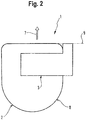
- Figure 2 show the corner cleaning module 3 and the robot unit 2 in plan view, the corner cleaning module 3 being fastened in a predetermined position relative to the robot unit 2 by means of a mechanical interface. It can be seen that the corner cleaning module 3 extends laterally to the forward direction 7 so far that the suction mouth 6 shown in broken lines is located outside the outer contour 8 of the robot unit 2.
- the suction mouth 6 with suction channel is preferably on one of the front corners placed outside the outer contour 8 of the robot unit 2. This ensures that the suction mouth 6 can penetrate deeply into corners to be cleaned.
- the suction mouth 6 is preferably attached to the side of the robot unit 2.
- the position of the suction mouth 6 can be selected such that the end face of the suction mouth 6, viewed in the forward direction 7, is in a common plane 9 with the end face of the robot unit 2. In this case, the suction mouth 6 is flush with the end face of the robot unit 2.
- the robot unit 2 comprises electrical or optical distance sensors or is equipped with bumpers.
- the protective mechanisms available for the robot unit 2 are not designed to protect the suction mouth 6 from collisions with the wall or with objects and to protect furnishings. In this respect, additional mechanisms for recognizing and avoiding collisions with the suction mouth 6 are required here.
- the suction mouth could be equipped with independent sensors for determining the distance or for detecting collisions, for example with optical or electronic distance sensors or with mechanical sensors for collision detection.
- the signals from these sensors could either be fed to a control unit located on the corner cleaning module for further evaluation or else transmitted to the robot unit via the data interface and evaluated by the control unit there, which is also responsible for controlling the route.
- a second strategy is to equip the suction mouth with bumpers or to manufacture the suction mouth itself from an elastically deformable material that deforms when it collides with a wall or an object.
- the suction mouth could consist entirely or partially of an elastomer, for example of Rubber, silicone or another suitable elastomer that is sufficiently soft to avoid damage in the event of a collision.
- the suction mouth can, for example, as in the Figures 3a and 3b shown have a polygonal cross-sectional area, wherein in Figure 3a a suction mouth 10 with a rectangular cross section and in Figure 3b a suction mouth 11 with a triangular cross section is shown, although other polygonal cross sections are also possible.
- the edges of the suction mouth can either be designed as tapered edges or as rounded edges. Alternatively, the use of a suction mouth with a round, oval or elliptical cross-sectional area is also possible.
- a suction mouth 12 is shown with a circular cross section and Figure 3d shows a suction mouth 13 with an oval cross section.
- the suction mouth can be designed as a suction mouth that widens conically from the top to the bottom.
- At or around the suction mouth at least partially sealing elements such as e.g. Bristles can be arranged. This additional seal improves the suction effect.
- the bristles can look like brooms and remove the dust from the corners.
- Rotating brushes can also be arranged within the suction mouth, for example, the axis of which is arranged perpendicularly, horizontally or obliquely to the floor. With the help of such rotating brushes, the dust can be captured in the corner, guided to the center of the suction mouth and then sucked in.
- the corner cleaning module 3 comprises the suction mouth 6 with the suction channel, at which dirt and dust-laden air is sucked in.
- the suction mouth 6 forms the air inlet for the flow path in the corner cleaning module.
- a dust collecting container 14 in which dust and dirt are separated from the suction air flow.
- the pre-cleaned air is fed via a filter 15 to a blower unit 16, which is designed for the To generate suction air flow in the corner cleaning module 3.
- the air From the exhaust air side of the blower unit 16, the air reaches a blow-out area 17, which forms the air outlet for the cleaned air.
- a control unit 18 is provided in the corner cleaning module 3, which is connected to the control unit of the robot unit 2 via a data interface 19.
- the control unit 18 can, for example, receive sensor signals from sensors attached to the suction mouth 6 or from sensors in the dust collecting container 14 and forward them to the control unit of the robot unit 2.
- the blower unit 16 can be controlled by the control unit 18, wherein the control commands for the blower unit 16 can be generated either by the control unit 18 itself or by the control unit of the robot unit 2.
- the control unit on the robot unit side is responsible for navigating the robot unit on the surface to be cleaned and for generating suitable control commands for the chassis.
- the control unit can be designed, for example, to determine suitable travel paths for the movement of the robot unit. Sensor signals from sensors attached to the robot unit, for example, can serve as the starting point for determining the travel paths.
- mapping means can be provided or stored, which provide information about the geometry of the surface to be cleaned or the space to be cleaned. This information can be used by the control unit as a starting point for determining the travel routes.
- different paths are required for corner and edge cleaning than for surface cleaning of the room or surface to be cleaned.
- the robot unit While the respective surface is swept as completely as possible by the robot unit in accordance with at least one movement pattern during the surface cleaning, it is necessary for the corner and edge cleaning that the robot unit has the external limitation of the space or the surface, which is predetermined, for example, by walls and other objects can, leaves at a certain distance from the boundary.
- This process which is decisive for corner and edge cleaning, in which the outer boundary of the room or surface is covered, is also referred to as the wall-following process.
- the robot unit 2 should change the movement pattern to a movement pattern suitable for corner and edge cleaning, in which the robot unit 2 moves over the outer boundary.
- This adjustment of the movement pattern can take place by means of a suitable data exchange between the control unit 18 on the side of the corner cleaning module and the control unit provided on the robot unit 2.
- the control unit 18 of the control unit can indicate that the attached module is a corner cleaning module 3.
- the control unit will then determine a route suitable for corner and edge cleaning and control the drive unit so that this route is traveled.
- mapping means are present on the control unit side, in particular devices for recording, storing and evaluating geometric properties of the space to be cleaned or the surface to be cleaned.
- the geometry information stored in the mapping means comprises the dimensions of the respective room or area.
- this geometric information can also include information about the positions and dimensions of free-standing obstacles such as furniture and other furnishings.
- the mapping means can include, for example, information on the course of the transitions from one room to the next.
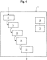
- an outermost circulation 24 along walls and obstacles can also be determined from this geometry information.
- This outermost circulation 24 is in Figure 5 drawn in as a dashed line and is suitable as a route for cleaning corners and edges.
- This outermost circulation 24 could, on the one hand, be derived directly from the geometry data.
- Known free-standing obstacles are also taken into account when determining this outermost circulation 24.
- the route for corner and edge cleaning can therefore be derived from the totality of possible routes within a room or area to be cleaned, as they must be determined for surface cleaning anyway.
- the advantage is that the information already determined for surface cleaning can be used as the basis for determining the route for corner and edge cleaning.
Landscapes
- Engineering & Computer Science (AREA)
- Mechanical Engineering (AREA)
- Electric Vacuum Cleaner (AREA)
Claims (9)
- Module de nettoyage dans les coins (3) présentant :une bouche d'aspiration (6) destinée à aspirer une zone d'aspiration,une unité de ventilateur (16) qui est conçue pour produire un courant d'air d'aspiration,le trajet d'écoulement pour le courant d'air d'aspiration s'étendant vers la bouche d'aspiration (6), etune interface mécanique au moyen de laquelle une liaison mécanique amovible peut être réalisée entre le module de nettoyage dans les coins (3) et une unité de robot (2),la bouche d'aspiration (6) étant disposée sur le module de nettoyage dans les coins (3) de manière à ce que lorsque le module de nettoyage dans les coins (3) est couplé à l'unité de robot (2), la bouche d'aspiration (6) fasse saillie au-dessus d'un contour extérieur (8) de l'unité de robot (2) de manière à ce qu'une zone d'aspiration en dehors du contour extérieur (8) de l'unité de robot (2) puisse être aspirée au moyen de la bouche d'aspiration (6), la zone d'aspiration de la bouche d'aspiration (6) se trouvant en dehors du contour extérieur (8) de l'unité de robot (2),le module de nettoyage dans les coins (3), lorsque le module de nettoyage dans les coins (3) est couplé à l'unité de robot (2), faisant saillie, en vue en direction de déplacement vers l'avant (7) de l'unité de robot (2), latéralement au-dessus du contour extérieur (8) de l'unité de robot (2), et la bouche d'aspiration (6), en vue en direction de déplacement vers l'avant (7) de l'unité de robot (2), étant disposée latéralement de l'unité de robot (2),caractérisé en ce quele module de nettoyage dans les coins (3) présente une interface d'énergie par l'intermédiaire de laquelle le module de nettoyage dans les coins (3) peut être alimenté en énergie depuis l'unité de robot (2).
- Robot de nettoyage (1) à structure modulaire, lequel présente :une unité de robot (2),un module de nettoyage dans les coins (3), lequel présenteune bouche d'aspiration (6) destinée à aspirer une zone d'aspiration,une unité de ventilateur (16) qui est conçue pour produire un courant d'air d'aspiration,le trajet d'écoulement pour le courant d'air d'aspiration s'étendant vers la bouche d'aspiration (6), etune interface mécanique par l'intermédiaire de laquelle le module de nettoyage dans les coins (3) est relié à l'unité de robot (2) en une liaison mécanique amovible,la bouche d'aspiration (6) étant disposée sur le module de nettoyage dans les coins (3) de manière à ce que la bouche d'aspiration (6) fasse saillie au-dessus du contour extérieur (8) de l'unité de robot (2) de manière à ce qu'une zone d'aspiration en dehors du contour extérieur (8) de l'unité de robot (2) puisse être aspirée au moyen de la bouche d'aspiration (6), la zone d'aspiration de la bouche d'aspiration (6) se trouvant en dehors du contour extérieur (8) de l'unité de robot (2),le module de nettoyage dans les coins (3), en vue en direction de déplacement vers l'avant (7) de l'unité de robot (2), dépassant latéralement au-dessus du contour extérieur (8) de l'unité de robot (2),la bouche d'aspiration (6), en vue en direction de déplacement vers l'avant (7) de l'unité de robot (2), étant disposée latéralement de l'unité de robot (2),caractérisé en ce quele module de nettoyage dans les coins (3) présente une interface d'énergie par l'intermédiaire de laquelle le module de nettoyage dans les coins (3) peut être alimenté en énergie depuis l'unité de robot (2),et en ce que l'unité de robot (2) comprend un châssis doté d'une unité d'entraînement et une unité de commande.
- Robot de nettoyage (1) selon la revendication 2, caractérisé en ce que le module de nettoyage dans les coins (3) est placé sur l'unité de robot (2) à une position prédéfinie.
- Robot de nettoyage (1) selon la revendication 2 ou 3, caractérisé en ce que le module de nettoyage dans les coins (3) est réalisé en tant que dispositif d'aspirateur autonome.
- Robot de nettoyage (1) selon l'une quelconque des revendications 2 à 4, caractérisé en ce que le module de nettoyage dans les coins (3) présente une interface de données (19) qui est conçue pour permettre un échange d'au moins une de données et d'instructions de commande entre le module de nettoyage dans les coins (3) et l'unité de robot (2).
- Robot de nettoyage (1) selon l'une quelconque des revendications 2 à 5, caractérisé en ce que la forme et le dimensionnement de la bouche d'aspiration (6) sont conçus pour nettoyer des coins et des bords d'une surface à nettoyer ou d'une pièce à nettoyer.
- Robot de nettoyage (1) selon l'une quelconque des revendications 2 à 6, caractérisé en ce que la bouche d'aspiration (6) est entièrement ou partiellement constituée d'un élastomère.
- Robot de nettoyage (1) selon l'une quelconque des revendications 2 à 7, caractérisé en ce que le trajet d'écoulement du courant d'air d'aspiration s'étend de la bouche d'aspiration (6) jusqu'à au moins une ouverture de sortie en passant par un dispositif de séparation de poussière (14) et l'unité de ventilateur (16).
- Robot de nettoyage (1) selon l'une quelconque des revendications 2 à 8, caractérisé en ce que l'unité de commande est conçue pour commander l'unité de robot (2) avec le module de nettoyage dans les coins (3) de manière à ce que l'unité de robot (2) se déplace le long d'une limitation extérieure d'une surface ou d'une pièce à nettoyer suivant un procédé de poursuite de mur.
Applications Claiming Priority (1)
| Application Number | Priority Date | Filing Date | Title |
|---|---|---|---|
| DE102017208963.6A DE102017208963A1 (de) | 2017-05-29 | 2017-05-29 | Eckenreinigungsmodul für modular aufgebaute Reinigungsroboter |
Publications (2)
| Publication Number | Publication Date |
|---|---|
| EP3409168A1 EP3409168A1 (fr) | 2018-12-05 |
| EP3409168B1 true EP3409168B1 (fr) | 2020-01-08 |
Family
ID=62196430
Family Applications (1)
| Application Number | Title | Priority Date | Filing Date |
|---|---|---|---|
| EP18172808.0A Active EP3409168B1 (fr) | 2017-05-29 | 2018-05-17 | Module de nettoyage d'angle pour robots de nettoyage modulaires |
Country Status (2)
| Country | Link |
|---|---|
| EP (1) | EP3409168B1 (fr) |
| DE (1) | DE102017208963A1 (fr) |
Cited By (1)
| Publication number | Priority date | Publication date | Assignee | Title |
|---|---|---|---|---|
| DE102021212783A1 (de) | 2021-11-12 | 2023-05-17 | Volkswagen Aktiengesellschaft | Reinigungsroboter |
Families Citing this family (7)
| Publication number | Priority date | Publication date | Assignee | Title |
|---|---|---|---|---|
| EP3668362B1 (fr) * | 2017-08-16 | 2023-07-19 | SharkNinja Operating LLC | Aspirateur robot |
| DE102019209413B4 (de) * | 2019-06-27 | 2025-07-03 | Volkswagen Aktiengesellschaft | Modularer Saugroboter |
| DE102019209419A1 (de) * | 2019-06-27 | 2020-12-31 | Volkswagen Aktiengesellschaft | Saugroboter mit flexibler Saugdüse |
| CN111920342A (zh) * | 2020-08-02 | 2020-11-13 | 珠海市一微半导体有限公司 | 清洁机器人 |
| CN113057528A (zh) * | 2021-02-22 | 2021-07-02 | 江苏柯林博特智能科技有限公司 | 一种配有监控实时监控效果的清洁机器人 |
| CN116164343B (zh) * | 2023-02-01 | 2026-04-14 | 宁波奥克斯电气有限公司 | 一种柜式空调 |
| EP4702904A1 (fr) * | 2024-08-26 | 2026-03-04 | Vorwerk & Co. Interholding GmbH | Appareil de nettoyage, appareil de base pour un appareil de nettoyage et système de nettoyage |
Family Cites Families (14)
| Publication number | Priority date | Publication date | Assignee | Title |
|---|---|---|---|---|
| JPH07319542A (ja) * | 1994-05-30 | 1995-12-08 | Minolta Co Ltd | 自走式作業車 |
| US5709007A (en) | 1996-06-10 | 1998-01-20 | Chiang; Wayne | Remote control vacuum cleaner |
| US6514356B2 (en) | 2001-01-12 | 2003-02-04 | Royal Appliance Mfg. Co. | Edge cleaner for vacuum cleaner |
| DE10139213A1 (de) | 2001-08-09 | 2003-02-27 | Vorwerk Co Interholding | Saugreinigungsvorsatz für einen Staubsauger |
| US20050209736A1 (en) | 2002-11-13 | 2005-09-22 | Figla Co., Ltd. | Self-propelled working robot |
| JP2004267236A (ja) * | 2003-03-05 | 2004-09-30 | Hitachi Ltd | 自走式掃除機およびそれに用いる充電装置 |
| DE102005046813A1 (de) | 2005-09-30 | 2007-04-05 | Vorwerk & Co. Interholding Gmbh | Verfahren zum Betreiben eines selbsttätig verfahrbaren Haushaltsgerätes sowie Verfahren zum Betreiben einer Basisstation |
| US20070113373A1 (en) | 2005-11-21 | 2007-05-24 | Sharp Kabushiki Kaisha | Vacuum cleaner |
| DE102007036163B4 (de) | 2007-08-02 | 2011-12-08 | BSH Bosch und Siemens Hausgeräte GmbH | Verfahren und eine Vorrichtung zum Festlegen eines Fahrmusters eines Bodenpflegegerätes, insbesondere eines Staubsammelroboters in einem Raum oder abgegrenzten Bereich |
| DE102007060750B4 (de) * | 2007-12-17 | 2020-07-30 | Vorwerk & Co. Interholding Gmbh | Bodenbearbeitungsgerät |
| CN104248395B (zh) | 2008-04-24 | 2018-06-22 | 艾罗伯特公司 | 用于机器人使能的移动产品的定位、位置控制和导航系统的应用 |
| JP2013233305A (ja) | 2012-05-09 | 2013-11-21 | Mitsubishi Electric Corp | 自走式掃除機 |
| TWM466626U (zh) | 2013-03-26 | 2013-12-01 | Liang-Xiong Wang | 清潔機 |
| KR102125334B1 (ko) * | 2014-01-06 | 2020-06-22 | 삼성전자주식회사 | 로봇 청소기 및 그 제어방법 |
-
2017
- 2017-05-29 DE DE102017208963.6A patent/DE102017208963A1/de not_active Withdrawn
-
2018
- 2018-05-17 EP EP18172808.0A patent/EP3409168B1/fr active Active
Non-Patent Citations (1)
| Title |
|---|
| None * |
Cited By (2)
| Publication number | Priority date | Publication date | Assignee | Title |
|---|---|---|---|---|
| DE102021212783A1 (de) | 2021-11-12 | 2023-05-17 | Volkswagen Aktiengesellschaft | Reinigungsroboter |
| DE102021212783B4 (de) | 2021-11-12 | 2025-02-06 | Volkswagen Aktiengesellschaft | Reinigungsroboter |
Also Published As
| Publication number | Publication date |
|---|---|
| DE102017208963A1 (de) | 2018-11-29 |
| EP3409168A1 (fr) | 2018-12-05 |
Similar Documents
| Publication | Publication Date | Title |
|---|---|---|
| EP3409168B1 (fr) | Module de nettoyage d'angle pour robots de nettoyage modulaires | |
| EP3409165B1 (fr) | Dispositif de support sur un robot de nettoyage | |
| DE102010000607B4 (de) | Als Basisstation für ein selbsttätig verfahrbares Saug- und/oder Kehrgerät einsetzbarer Haushaltsstaubsauger | |
| EP3351157B1 (fr) | Appareil de nettoyage se déplaçant automatiquement | |
| EP2982285B1 (fr) | Appareil de nettoyage de sol destine au nettoyage sec et humide et procede de fonctionnement d'un appareil de nettoyage de sol automobile | |
| EP3047783B1 (fr) | Robot aspirateur | |
| EP3351156B1 (fr) | Appareil de nettoyage se déplaçant automatiquement | |
| EP3787455B1 (fr) | Robot nettoyeur pour le nettoyage autonome d'un intérieur de véhicule | |
| EP3047771B1 (fr) | Robot aspirateur | |
| DE10258781A1 (de) | Automatischer Staubsauger mit Luftumwälzung | |
| DE102010017213A1 (de) | Entleerungsstation für einen Schmutzsammelbehälter eines Reinigungsgerätes sowie Verfahren hierzu | |
| DE102015103825A1 (de) | Entleeren eines Staubraums eines Staubsaugers | |
| WO2022200524A2 (fr) | Robot mobile autonome et station de service | |
| EP3310233A1 (fr) | Buse d'aspiration pour un aspirateur | |
| DE102017208960A1 (de) | Staubsauger mit einem motorisch betriebenen Dichtmittel | |
| DE102019101337A1 (de) | System mit einem ersten Bodenbearbeitungsgerät und einem zweiten Bodenbearbeitungsgerät sowie Verfahren zum Betrieb eines solchen Systems | |
| DE202017100064U1 (de) | Sich selbsttätig fortbewegendes Reinigungsgerät | |
| WO2020126826A1 (fr) | Procédé de nettoyage d'un habitacle d'un véhicule, système, dispositif d'alimentation et véhicule | |
| EP3047781A1 (fr) | Aspirateur-traîneau à activation autonome, procédé d'aspiration de poussières et utilisation d'un aspirateur-traîneau utilisable à activation autonome | |
| EP3725202A1 (fr) | Robot aspirateur autonome ainsi que système comprenant un robot aspirateur autonome et un appareil de nettoyage par aspiration externe | |
| EP3047772B1 (fr) | Robot aspirateur | |
| EP4278940B1 (fr) | Dispositif pour le nettoyage des surfaces sales | |
| WO2020126830A1 (fr) | Procédé de nettoyage d'un habitacle d'un véhicule, robot nettoyeur, robot positionneur, système et véhicule | |
| DE102015114265A1 (de) | Saugroboter sowie Verfahren zur Reinigung einer Bodenfläche | |
| EP3437535B1 (fr) | Aspirateur |
Legal Events
| Date | Code | Title | Description |
|---|---|---|---|
| PUAI | Public reference made under article 153(3) epc to a published international application that has entered the european phase |
Free format text: ORIGINAL CODE: 0009012 |
|
| STAA | Information on the status of an ep patent application or granted ep patent |
Free format text: STATUS: THE APPLICATION HAS BEEN PUBLISHED |
|
| AK | Designated contracting states |
Kind code of ref document: A1 Designated state(s): AL AT BE BG CH CY CZ DE DK EE ES FI FR GB GR HR HU IE IS IT LI LT LU LV MC MK MT NL NO PL PT RO RS SE SI SK SM TR |
|
| AX | Request for extension of the european patent |
Extension state: BA ME |
|
| STAA | Information on the status of an ep patent application or granted ep patent |
Free format text: STATUS: REQUEST FOR EXAMINATION WAS MADE |
|
| 17P | Request for examination filed |
Effective date: 20190605 |
|
| RBV | Designated contracting states (corrected) |
Designated state(s): AL AT BE BG CH CY CZ DE DK EE ES FI FR GB GR HR HU IE IS IT LI LT LU LV MC MK MT NL NO PL PT RO RS SE SI SK SM TR |
|
| GRAP | Despatch of communication of intention to grant a patent |
Free format text: ORIGINAL CODE: EPIDOSNIGR1 |
|
| STAA | Information on the status of an ep patent application or granted ep patent |
Free format text: STATUS: GRANT OF PATENT IS INTENDED |
|
| INTG | Intention to grant announced |
Effective date: 20190829 |
|
| GRAS | Grant fee paid |
Free format text: ORIGINAL CODE: EPIDOSNIGR3 |
|
| GRAA | (expected) grant |
Free format text: ORIGINAL CODE: 0009210 |
|
| STAA | Information on the status of an ep patent application or granted ep patent |
Free format text: STATUS: THE PATENT HAS BEEN GRANTED |
|
| AK | Designated contracting states |
Kind code of ref document: B1 Designated state(s): AL AT BE BG CH CY CZ DE DK EE ES FI FR GB GR HR HU IE IS IT LI LT LU LV MC MK MT NL NO PL PT RO RS SE SI SK SM TR |
|
| REG | Reference to a national code |
Ref country code: GB Ref legal event code: FG4D Free format text: NOT ENGLISH |
|
| REG | Reference to a national code |
Ref country code: CH Ref legal event code: EP |
|
| REG | Reference to a national code |
Ref country code: DE Ref legal event code: R096 Ref document number: 502018000609 Country of ref document: DE |
|
| REG | Reference to a national code |
Ref country code: IE Ref legal event code: FG4D Free format text: LANGUAGE OF EP DOCUMENT: GERMAN |
|
| REG | Reference to a national code |
Ref country code: AT Ref legal event code: REF Ref document number: 1221621 Country of ref document: AT Kind code of ref document: T Effective date: 20200215 |
|
| REG | Reference to a national code |
Ref country code: NL Ref legal event code: MP Effective date: 20200108 |
|
| REG | Reference to a national code |
Ref country code: LT Ref legal event code: MG4D |
|
| PG25 | Lapsed in a contracting state [announced via postgrant information from national office to epo] |
Ref country code: FI Free format text: LAPSE BECAUSE OF FAILURE TO SUBMIT A TRANSLATION OF THE DESCRIPTION OR TO PAY THE FEE WITHIN THE PRESCRIBED TIME-LIMIT Effective date: 20200108 Ref country code: LT Free format text: LAPSE BECAUSE OF FAILURE TO SUBMIT A TRANSLATION OF THE DESCRIPTION OR TO PAY THE FEE WITHIN THE PRESCRIBED TIME-LIMIT Effective date: 20200108 Ref country code: RS Free format text: LAPSE BECAUSE OF FAILURE TO SUBMIT A TRANSLATION OF THE DESCRIPTION OR TO PAY THE FEE WITHIN THE PRESCRIBED TIME-LIMIT Effective date: 20200108 Ref country code: NL Free format text: LAPSE BECAUSE OF FAILURE TO SUBMIT A TRANSLATION OF THE DESCRIPTION OR TO PAY THE FEE WITHIN THE PRESCRIBED TIME-LIMIT Effective date: 20200108 Ref country code: PT Free format text: LAPSE BECAUSE OF FAILURE TO SUBMIT A TRANSLATION OF THE DESCRIPTION OR TO PAY THE FEE WITHIN THE PRESCRIBED TIME-LIMIT Effective date: 20200531 Ref country code: NO Free format text: LAPSE BECAUSE OF FAILURE TO SUBMIT A TRANSLATION OF THE DESCRIPTION OR TO PAY THE FEE WITHIN THE PRESCRIBED TIME-LIMIT Effective date: 20200408 |
|
| PG25 | Lapsed in a contracting state [announced via postgrant information from national office to epo] |
Ref country code: HR Free format text: LAPSE BECAUSE OF FAILURE TO SUBMIT A TRANSLATION OF THE DESCRIPTION OR TO PAY THE FEE WITHIN THE PRESCRIBED TIME-LIMIT Effective date: 20200108 Ref country code: BG Free format text: LAPSE BECAUSE OF FAILURE TO SUBMIT A TRANSLATION OF THE DESCRIPTION OR TO PAY THE FEE WITHIN THE PRESCRIBED TIME-LIMIT Effective date: 20200408 Ref country code: IS Free format text: LAPSE BECAUSE OF FAILURE TO SUBMIT A TRANSLATION OF THE DESCRIPTION OR TO PAY THE FEE WITHIN THE PRESCRIBED TIME-LIMIT Effective date: 20200508 Ref country code: GR Free format text: LAPSE BECAUSE OF FAILURE TO SUBMIT A TRANSLATION OF THE DESCRIPTION OR TO PAY THE FEE WITHIN THE PRESCRIBED TIME-LIMIT Effective date: 20200409 Ref country code: SE Free format text: LAPSE BECAUSE OF FAILURE TO SUBMIT A TRANSLATION OF THE DESCRIPTION OR TO PAY THE FEE WITHIN THE PRESCRIBED TIME-LIMIT Effective date: 20200108 Ref country code: LV Free format text: LAPSE BECAUSE OF FAILURE TO SUBMIT A TRANSLATION OF THE DESCRIPTION OR TO PAY THE FEE WITHIN THE PRESCRIBED TIME-LIMIT Effective date: 20200108 |
|
| REG | Reference to a national code |
Ref country code: DE Ref legal event code: R097 Ref document number: 502018000609 Country of ref document: DE |
|
| PG25 | Lapsed in a contracting state [announced via postgrant information from national office to epo] |
Ref country code: CZ Free format text: LAPSE BECAUSE OF FAILURE TO SUBMIT A TRANSLATION OF THE DESCRIPTION OR TO PAY THE FEE WITHIN THE PRESCRIBED TIME-LIMIT Effective date: 20200108 Ref country code: RO Free format text: LAPSE BECAUSE OF FAILURE TO SUBMIT A TRANSLATION OF THE DESCRIPTION OR TO PAY THE FEE WITHIN THE PRESCRIBED TIME-LIMIT Effective date: 20200108 Ref country code: SK Free format text: LAPSE BECAUSE OF FAILURE TO SUBMIT A TRANSLATION OF THE DESCRIPTION OR TO PAY THE FEE WITHIN THE PRESCRIBED TIME-LIMIT Effective date: 20200108 Ref country code: SM Free format text: LAPSE BECAUSE OF FAILURE TO SUBMIT A TRANSLATION OF THE DESCRIPTION OR TO PAY THE FEE WITHIN THE PRESCRIBED TIME-LIMIT Effective date: 20200108 Ref country code: DK Free format text: LAPSE BECAUSE OF FAILURE TO SUBMIT A TRANSLATION OF THE DESCRIPTION OR TO PAY THE FEE WITHIN THE PRESCRIBED TIME-LIMIT Effective date: 20200108 Ref country code: EE Free format text: LAPSE BECAUSE OF FAILURE TO SUBMIT A TRANSLATION OF THE DESCRIPTION OR TO PAY THE FEE WITHIN THE PRESCRIBED TIME-LIMIT Effective date: 20200108 Ref country code: ES Free format text: LAPSE BECAUSE OF FAILURE TO SUBMIT A TRANSLATION OF THE DESCRIPTION OR TO PAY THE FEE WITHIN THE PRESCRIBED TIME-LIMIT Effective date: 20200108 |
|
| PLBE | No opposition filed within time limit |
Free format text: ORIGINAL CODE: 0009261 |
|
| STAA | Information on the status of an ep patent application or granted ep patent |
Free format text: STATUS: NO OPPOSITION FILED WITHIN TIME LIMIT |
|
| 26N | No opposition filed |
Effective date: 20201009 |
|
| PG25 | Lapsed in a contracting state [announced via postgrant information from national office to epo] |
Ref country code: IT Free format text: LAPSE BECAUSE OF FAILURE TO SUBMIT A TRANSLATION OF THE DESCRIPTION OR TO PAY THE FEE WITHIN THE PRESCRIBED TIME-LIMIT Effective date: 20200108 Ref country code: MC Free format text: LAPSE BECAUSE OF FAILURE TO SUBMIT A TRANSLATION OF THE DESCRIPTION OR TO PAY THE FEE WITHIN THE PRESCRIBED TIME-LIMIT Effective date: 20200108 |
|
| PG25 | Lapsed in a contracting state [announced via postgrant information from national office to epo] |
Ref country code: PL Free format text: LAPSE BECAUSE OF FAILURE TO SUBMIT A TRANSLATION OF THE DESCRIPTION OR TO PAY THE FEE WITHIN THE PRESCRIBED TIME-LIMIT Effective date: 20200108 Ref country code: SI Free format text: LAPSE BECAUSE OF FAILURE TO SUBMIT A TRANSLATION OF THE DESCRIPTION OR TO PAY THE FEE WITHIN THE PRESCRIBED TIME-LIMIT Effective date: 20200108 |
|
| REG | Reference to a national code |
Ref country code: BE Ref legal event code: MM Effective date: 20200531 |
|
| PG25 | Lapsed in a contracting state [announced via postgrant information from national office to epo] |
Ref country code: LU Free format text: LAPSE BECAUSE OF NON-PAYMENT OF DUE FEES Effective date: 20200517 |
|
| PG25 | Lapsed in a contracting state [announced via postgrant information from national office to epo] |
Ref country code: IE Free format text: LAPSE BECAUSE OF NON-PAYMENT OF DUE FEES Effective date: 20200517 Ref country code: FR Free format text: LAPSE BECAUSE OF NON-PAYMENT OF DUE FEES Effective date: 20200531 |
|
| PG25 | Lapsed in a contracting state [announced via postgrant information from national office to epo] |
Ref country code: BE Free format text: LAPSE BECAUSE OF NON-PAYMENT OF DUE FEES Effective date: 20200531 |
|
| REG | Reference to a national code |
Ref country code: CH Ref legal event code: PL |
|
| PG25 | Lapsed in a contracting state [announced via postgrant information from national office to epo] |
Ref country code: CH Free format text: LAPSE BECAUSE OF NON-PAYMENT OF DUE FEES Effective date: 20210531 Ref country code: LI Free format text: LAPSE BECAUSE OF NON-PAYMENT OF DUE FEES Effective date: 20210531 |
|
| PG25 | Lapsed in a contracting state [announced via postgrant information from national office to epo] |
Ref country code: TR Free format text: LAPSE BECAUSE OF FAILURE TO SUBMIT A TRANSLATION OF THE DESCRIPTION OR TO PAY THE FEE WITHIN THE PRESCRIBED TIME-LIMIT Effective date: 20200108 Ref country code: MT Free format text: LAPSE BECAUSE OF FAILURE TO SUBMIT A TRANSLATION OF THE DESCRIPTION OR TO PAY THE FEE WITHIN THE PRESCRIBED TIME-LIMIT Effective date: 20200108 Ref country code: CY Free format text: LAPSE BECAUSE OF FAILURE TO SUBMIT A TRANSLATION OF THE DESCRIPTION OR TO PAY THE FEE WITHIN THE PRESCRIBED TIME-LIMIT Effective date: 20200108 |
|
| PG25 | Lapsed in a contracting state [announced via postgrant information from national office to epo] |
Ref country code: MK Free format text: LAPSE BECAUSE OF FAILURE TO SUBMIT A TRANSLATION OF THE DESCRIPTION OR TO PAY THE FEE WITHIN THE PRESCRIBED TIME-LIMIT Effective date: 20200108 Ref country code: AL Free format text: LAPSE BECAUSE OF FAILURE TO SUBMIT A TRANSLATION OF THE DESCRIPTION OR TO PAY THE FEE WITHIN THE PRESCRIBED TIME-LIMIT Effective date: 20200108 |
|
| GBPC | Gb: european patent ceased through non-payment of renewal fee |
Effective date: 20220517 |
|
| PG25 | Lapsed in a contracting state [announced via postgrant information from national office to epo] |
Ref country code: GB Free format text: LAPSE BECAUSE OF NON-PAYMENT OF DUE FEES Effective date: 20220517 |
|
| P01 | Opt-out of the competence of the unified patent court (upc) registered |
Effective date: 20230504 |
|
| REG | Reference to a national code |
Ref country code: AT Ref legal event code: MM01 Ref document number: 1221621 Country of ref document: AT Kind code of ref document: T Effective date: 20230517 |
|
| PG25 | Lapsed in a contracting state [announced via postgrant information from national office to epo] |
Ref country code: AT Free format text: LAPSE BECAUSE OF NON-PAYMENT OF DUE FEES Effective date: 20230517 |
|
| PG25 | Lapsed in a contracting state [announced via postgrant information from national office to epo] |
Ref country code: AT Free format text: LAPSE BECAUSE OF NON-PAYMENT OF DUE FEES Effective date: 20230517 |
|
| PGFP | Annual fee paid to national office [announced via postgrant information from national office to epo] |
Ref country code: DE Payment date: 20250531 Year of fee payment: 8 |
|
| PGFP | Annual fee paid to national office [announced via postgrant information from national office to epo] |
Ref country code: AT Payment date: 20260410 Year of fee payment: 5 |