EP3409236A1 - Zahnärztlicher abflachungsbohrer - Google Patents
Zahnärztlicher abflachungsbohrer Download PDFInfo
- Publication number
- EP3409236A1 EP3409236A1 EP16888312.2A EP16888312A EP3409236A1 EP 3409236 A1 EP3409236 A1 EP 3409236A1 EP 16888312 A EP16888312 A EP 16888312A EP 3409236 A1 EP3409236 A1 EP 3409236A1
- Authority
- EP
- European Patent Office
- Prior art keywords
- drill
- housing
- lance
- blade
- alveolar bone
- Prior art date
- Legal status (The legal status is an assumption and is not a legal conclusion. Google has not performed a legal analysis and makes no representation as to the accuracy of the status listed.)
- Granted
Links
Images


Classifications
-
- A—HUMAN NECESSITIES
- A61—MEDICAL OR VETERINARY SCIENCE; HYGIENE
- A61C—DENTISTRY; APPARATUS OR METHODS FOR ORAL OR DENTAL HYGIENE
- A61C8/00—Means to be fixed to the jaw-bone for consolidating natural teeth or for fixing dental prostheses thereon; Dental implants; Implanting tools
- A61C8/0089—Implanting tools or instruments
-
- A—HUMAN NECESSITIES
- A61—MEDICAL OR VETERINARY SCIENCE; HYGIENE
- A61B—DIAGNOSIS; SURGERY; IDENTIFICATION
- A61B17/00—Surgical instruments, devices or methods
- A61B17/16—Instruments for performing osteoclasis; Drills or chisels for bones; Trepans
- A61B17/1662—Instruments for performing osteoclasis; Drills or chisels for bones; Trepans for particular parts of the body
- A61B17/1673—Instruments for performing osteoclasis; Drills or chisels for bones; Trepans for particular parts of the body for the jaw
-
- A—HUMAN NECESSITIES
- A61—MEDICAL OR VETERINARY SCIENCE; HYGIENE
- A61C—DENTISTRY; APPARATUS OR METHODS FOR ORAL OR DENTAL HYGIENE
- A61C1/00—Dental machines for boring or cutting ; General features of dental machines or apparatus, e.g. hand-piece design
- A61C1/08—Machine parts specially adapted for dentistry
-
- A—HUMAN NECESSITIES
- A61—MEDICAL OR VETERINARY SCIENCE; HYGIENE
- A61C—DENTISTRY; APPARATUS OR METHODS FOR ORAL OR DENTAL HYGIENE
- A61C3/00—Dental tools or instruments
- A61C3/02—Tooth drilling or cutting instruments; Instruments acting like a sandblast machine
-
- A—HUMAN NECESSITIES
- A61—MEDICAL OR VETERINARY SCIENCE; HYGIENE
- A61C—DENTISTRY; APPARATUS OR METHODS FOR ORAL OR DENTAL HYGIENE
- A61C8/00—Means to be fixed to the jaw-bone for consolidating natural teeth or for fixing dental prostheses thereon; Dental implants; Implanting tools
-
- B—PERFORMING OPERATIONS; TRANSPORTING
- B23—MACHINE TOOLS; METAL-WORKING NOT OTHERWISE PROVIDED FOR
- B23B—TURNING; BORING
- B23B51/00—Tools for drilling machines
- B23B51/08—Drills combined with tool parts or tools for performing additional working
Definitions
- the inventive concept relates to a dental flattening drill, and more particularly, to a dental flattening drill which may enable easy, accurate, and previous drilling at a position for placing a fixture with respect to an irregular alveolar bone like a thin ridge and flattening an area of an end portion of the alveolar bone so that the fixture can be stably fixed at an accurate position.
- An implant originally means a substitute used to restore lost human tissues.
- the implant refers to a series of procedures to transplant an artificial tooth.
- the implant is a series of dental procedures to restore a function of a tooth by placing a fixture, which is a dental root formed of titanium and having no rejection to a human body, in an alveolar bone where a tooth is lost, and then fixing an artificial tooth thereto.
- surrounding teeth or bones may be damaged as time passes.
- the implant since the implant does not harm the surrounding tooth tissues, provides the same function and shape as a natural tooth, has no tooth decay, the implant may be used semi-permanently.
- an implant surgery In an artificial tooth surgery (referred to as an implant surgery), a screw hole is formed by using a drill in an alveolar bone at a position where a fixture is to be placed, the fixture is placed in the screw hole to have osseointegration with the bone forming an artificial dental root, and an abutment is coupled to the fixture and crowned with an artificial tooth that is a final prosthesis.
- the implant as above may facilitate restoration of a single missing tooth, enhance the function of a denture for partially toothless and fully toothless patients, improve an aesthetic aspect of dental prosthesis restoration, and furthermore distribute excessive stress applied to surrounding support bone tissues and stabilize a row of teeth.
- a screw hole is formed by punching a hole in the alveolar bone by using a drill.
- the drill work is briefly discussed below.
- the drill work described below is a mere example and there may be a variety of types of drill works.
- a position where a fixture is to be placed is determined on a surface of the alveolar bon by using a round drill as an initial drill,
- a hole of a predetermined depth is punched by mounting a guide drill on a predetermined tool, with water supplied to the alveolar bone.
- the hole is enlarged by using a first drill with water supplied to the alveolar bone, and an end portion of the hole is enlarged by using a pilot drill with water supplied to the alveolar bone.
- a lower end portion of the hole is enlarged by using a final drill with water supplied to the alveolar bone.
- the screw hole for placing a fixture is completed by forming a screw thread in the hole by using a tap drill with water supplied to the alveolar bone.
- the above drill work that is, the forming of a screw hole in the alveolar bone by punching, may be generally applied to patients having a general mouth structure, in particular, having a normal ridge, that is, an end portion of the alveolar bone is large.
- the alveolar bone is not general, that is, irregular, for example, the end portion of the alveolar bone is excessively narrow, that is, the alveolar bone forms a thin ridge, the above method may not be employed as it is.
- the drill work is unavoidably performed on an inclined surface.
- the drill work may not be smoothly performed because the drill slips on the inclined surface. Accordingly, it is difficult to form the screw hole in the alveolar bone.
- the surgery may be made easy and accurate by using a drill suitable for the flattening work to flatten the end portion of the thin ridge.
- the inventive concept provides a dental flattening drill which may enable easy, accurate, and previous drilling at a position for placing a fixture with respect to an irregular alveolar bone like a thin ridge and flattening an area of an end portion of the alveolar bone so that the fixture can be stably fixed at an accurate position.
- the fixture since drilling is easily, accurately, and previously performed at a position for placing a fixture in an irregular alveolar bone like a thin ridge and an area of an end portion of the alveolar bone is flattened, the fixture can be stably fixed at an accurate position.
- a dental flattening drill including a drill lance having a drill blade that forms a placement hole by drilling an alveolar bone at a placement position where a fixture is to be placed by a preset depth, and a drill housing, to which the drill lance is detachably coupled, having a processing blade that flattens an area of the alveolar bone around the placement hole.
- the drill blade may be arranged radially inside an end mill processing blade of the drill housing.
- the drill blade of the drill lance may protrude more than the processing blade of the drill housing in a direction in which the drill lance is coupled to the drill housing.
- the drill lance may include a unit shaft having one end portion where the drill blade is formed, and a boss provided on one side of the unit shaft and caught and supported by the drill housing.
- the drill blade may be an awl type drill blade having a sharp end portion, the awl type drill blade may have a triangular pyramid shape, and the boss may have a polygonal sectional shape.
- the drill lance may further include a cylindrical insertion portion provided on a side surface of the boss toward the drill blade, and a tool mounting portion provided on the other end portion of the unit shaft.
- the processing blade may be continuously formed along a circumferential direction of a leading end portion of the drill housing.
- the drill housing may have a shape of a hollow pipe through which the drill lance passes.
- An alveolar bone crushed powder storing space portion storing alveolar bone crushed powder produced when the alveolar bone is crushed may be provided inside the drill housing.
- the processing blade may be an end mill processing blade having blades on a bottom and lateral surfaces.
- the drill housing may include a housing body having an end portion where the end mill processing blade is formed, a boss catching step, by which the boss of the drill lance is caught and supported, is provided in the housing body, and an insertion hole, into which a cylindrical insertion portion of the drill lance is inserted, is formed inside the boss catching step.
- An outer wall of the boss and an inner wall of the housing body contacting each other may have a non-circular shape.
- the dental flattening drill may further include a detachable coupling portion provided on the drill lance and the drill housing and detachably coupling the drill lance to the drill housing.
- the detachable coupling portion may include a ball plunger provided in any one of the drill lance and the drill housing and including a ball and an elastic member elastically pressing the ball, and a ball accommodation portion provided in the other one of the drill lance and the drill housing and accommodating the ball plunger.
- the ball plunger may protrude from an outer wall of one side of the drill lance, and the ball accommodation portion may be concavely formed in an inner wall of the drill housing and provided by a plural number to be regularly arranged in a circumferential direction of the inner wall of the drill housing.
- a guide groove guiding the ball of the ball plunger may be further formed in an inner wall of the drill housing where the ball accommodation portion is formed.
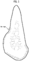
- the alveolar bone may be a thin ridge having an end portion that is relatively narrow and irregular.
- FIG. 1 illustrates a thin ridge alveolar bone.
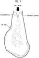
- FIG. 2 illustrates the thin ridge alveolar bone of FIG. 1 where a flattening work is performed.
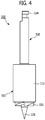
- FIG. 3 illustrates a process of performing a flattening work by using a dental flattening drill according to an embodiment.
- the alveolar bone is first punched and a screw hole is formed in a punched hole.
- a screw hole (or fixture placement hole) is formed without a preliminary preparation work.
- the alveolar bone is not general and is irregular, for example, the end portion of the alveolar bone is excessively narrow and irregular as illustrated in FIGS. 1 and 12 , that is, the alveolar bone has a thin ridge, the above method may not be employed as it is.
- a placement hole is formed by drilling the alveolar bone at a position where the fixture is to be placed by a predetermined depth and a flat surface is formed on an end portion of the thin ridge by flattening the end portion of the thin ridge.
- the present embodiment discloses a dental flattening drill 100 having a structure as illustrated in FIGS. 3 to 12 so that the fixture placement position may be easily, accurately, and previously drilled on an irregular alveolar bone having a thin ridge and further an area of the end portion thereof is flattened.
- the dental flattening drill 100 according to the present embodiment may be arranged on the end portion of the thin ridge, as illustrated in FIG. 3 , and used to form a placement hole and a flattened surface at the end portion of the thin ridge.
- efficiency of work may be improved.
- FIG. 4 is an enlarged view of the dental flattening drill of FIG. 3 .
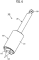
- FIGS. 5 and 6 are perspective views of the dental flattening drill viewed at different angles.
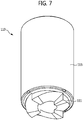
- FIGS. 7 and 8 are perspective views of a drill housing viewed at different angles.
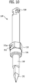
- FIGS. 9 and 10 are perspective views of a drill lance viewed at different angles.
- FIG. 11 is a vertical sectional view of FIG. 4 .
- FIG. 12 is an image showing steps of a process of placing a fixture after flattening a thin ridge by using a dental flattening drill, according to an embodiment.
- the dental flattening drill 100 may enable easy, accurate, and previous drilling at a position for placing a fixture with respect to an irregular alveolar bone like a thin ridge and flattening an area of an end portion of the alveolar bone, and may include two parts, that is, a drill lance 130 and a drill housing 110, which are disassembled from and assembled to each other.
- the drill lance 130 and the drill housing 110 may be assembled to each other and used as illustrated in FIG. 3 and may be disassembled from each other for cleaning the inside or for maintenance or repair.
- the drill lance 130 and the drill housing 110 assembled to each other may be arranged at the end portion of the thin ridge, as illustrated in FIG. 3 , to perform a drill work by being rotated by a separate drill driving equipment (not shown).
- the drill lance 130 drills the alveolar bone at a placement position where the fixture is to be placed by a predetermined depth, thereby forming the placement hole.
- the drill lance 130 maybe coupled to the drill housing 110 and rotated with the drill housing 110.
- the drill lance 130 may include a unit shaft 132 and a boss 133 provided at one side of the unit shaft 132 and caught and supported by a boss catching step 115.
- the unit shaft 132 is a long rod type structure, and a drill blade 131, that is, an awl type drill blade 131 having a sharp tip end is provided at one end portion of the unit shaft 132.
- the awl type drill blade 131 having a sharp end portion is provided so that a placement hole may be formed at a thin ridge by using the drill lance 130 as illustrated in FIGS. 2 and 3 .
- a placement hole having a shape as illustrated in FIGS. 2 and 3 may be formed in the thin ridge.
- the awl type drill blade 131 may be manufactured in a triangular pyramid shape.
- the awl type drill blade 131 provided on the drill lance 130 may be arranged radially inside an end mill processing blade 111 of the drill housing 110 that is described later.
- the awl type drill blade 131 of the drill lance 130 may protrude more than the end mill processing blade 111 of the drill housing 110 in a direction in which the drill lance 130 is coupled to the drill housing 110. Accordingly, the placement hole may be formed aside from a flattened surface.
- a tool mounting portion 134 is provided at the other end portion of the unit shaft 132.
- the tool mounting portion 134 may be a place to be used for mounting the dental flattening drill 100 according to the present embodiment on the separate drill driving equipment.
- the boss 133 is caught and supported by the boss catching step 115 of the drill housing 110.
- the drill lance 130 may be inserted into the drill housing 110 until the boss 133 is caught and supported by the boss catching step 115.
- an outer wall of the boss 133 and an inner wall of a housing body 113 contacting each other may have a non-circular shape so that the drill lance 130 is not freely rotated in the drill housing 110.
- the boss 133 has a shape like a hexagonal nut, and an inner wall of the housing body 113 is manufactured to have six faces corresponding to the hexagonal nut. Accordingly, when the boss 133 is inserted into the inner wall of the housing body 113, the boss 133 may not be freely rotated.
- boss 133 does not necessarily have the shape like the hexagonal nut, the right scope of the present inventive concept may not be limited to the shape presented on the drawings.
- a cylindrical insertion portion 135 may be provided on a side surface of the boss 133 toward the awl type drill blade 131.
- the cylindrical insertion portion 135 is inserted into an insertion hole 116 (see FIG. 8 ) of the drill housing 110 so that a coupling force between the drill lance 130 and the drill housing 110 may be improved.
- the drill housing 110 is a cylindrical structure to which the drill lance 130 is detachably coupled, and flattens an upper portion of the alveolar bone around the placement hole at the thin ridge as illustrated in FIG. 2 , thereby forming a flattened surface.
- a processing blade that is, the end mill processing blade 111 having blades on a bottom and lateral surfaces thereof, is formed on an end portion of the drill housing 110 to flatten the upper portion of the alveolar bone around the placement hole.
- the end mill processing blade 111 may be arranged radially outside the awl type drill blade 131 provided on the drill lance 130, forming the flattened surface on the thin ridge at its position.
- the drill housing 110 may have a hollow pipe shape so that the drill lance 130 may pass therethrough.
- the drill housing 110 may include the housing body 113 as a cylindrical structure.
- the end mill processing blade 111 for a flattening work of the thin ridge is formed on a leading end portion of the housing body 113 that is a hollow pipe structure.
- the end mill processing blade 111 also has a function of keeping a position of the awl type drill blade 131 provided on the drill lance 130 not to escape from the position when the awl type drill blade 131 is shaken during rotation.
- the end mill processing blade 111 rotates together with the awl type drill blade 131 and performs a flattening work on the upper portion of the thin ridge.
- the end mill processing blade 111 may be continuously formed in a circumferential direction on a leading end portion of the drill housing 110. Accordingly, shaking during the thin ridge flattening work decreases so that the flattening work may be stably performed.
- An alveolar bone crushed powder storing space portion 112 (see FIG. 11 ) for storing crushed powder of the alveolar bone produced when the alveolar bone is crushed is provided inside the housing body 113.
- the alveolar bone is crushed and crushed powder or some clods of the alveolar bone may be gathered inside the housing body 113, that is, a space between the drill lance 130 and the hosing body 113.
- the alveolar bone crushed powder gathered as above may be used during guide bone regeneration (GBR).
- GLR guide bone regeneration
- the alveolar bone crushed powder stored in the above space may be collected by separating the drill lance 130 and the drill housing 110.
- GBR refers to a surgery performed to promote bone formation using a shield film when no sufficient amount of alveolar bone exists around a placed fixture or the alveolar bone is insufficient at a place where the fixture is to be placed. In this state, it is known that, when a patient's own bone is used, the surgery may be more easily performed.
- a ball accommodation portion 152 that is a constituent element of a detachable coupling portion 150 is provided on an upper end portion of the inner wall of the housing body 113, which is described later.
- the boss catching step 115 is provided on the upper end portion of the inner wall of the housing body 113, forming a place where the boss 133 of the drill lance 130 is caught and supported.
- the drill lance 130 may be inserted into the drill housing 110 only to the boss catching step 115 where the boss 133 of the drill lance 130 is caught and supported. In this state, the drill lance 130 may be coupled or assembled to the drill housing 110.
- the dental flattening drill 100 may further include the detachable coupling portion 150 to allow the drill lance 130 to be detachably coupled to the drill housing 110.
- the detachable coupling portion 150 is provided between the drill lance 130 and the drill housing 110 and detachably coupling the drill lance 130 to the drill housing 110. Since the detachable coupling portion 150 is provided between the drill lance 130 and the drill housing 110 so that the drill lance 130 and the drill housing 110 are detachably coupled to each other, several drill housing (not shown) having different diameters may be commonly used with respect to one drill lance.
- the dental flattening drill according to the present embodiment may be easily applied to patients having different thin ridge areas.
- a drill housing having a relatively small diameter is first used and then a drill housing having a relatively large diameter may be used, a flattening work may be easily performed.
- the detachable coupling portion 150 applied to the dental flattening drill 100 of the present embodiment is provided in the boss 133 of the drill lance 130 and the housing body 113 of the drill housing 110.
- the detachable coupling portion 150 may be provided at a different position, regardless of positions.
- the detachable coupling portion 150 may include a ball plunger 151 provided on any one of the boss 133 of the drill lance 130 and the housing body 113 of the drill housing 110 and the ball accommodation portion 152 provided on the other one of the boss 133 of the drill lance 130 and the housing body 113 of the drill housing 110 and accommodating the ball plunger 151.
- the ball plunger 151 protrudes from an outer wall of the boss 133 of the drill lance 130, whereas the ball accommodation portion 152 is concavely formed in the inner wall of the housing body 113 of the drill housing 110.
- the ball plunger 151 may protrude from the inner wall of the housing body 113 of the drill housing 110, whereas the ball accommodation portion 152 may be concavely formed in the outer wall of the boss 133 of the drill lance 130.
- both the ball plunger 151 and the ball accommodation portion 152 is provided by one.
- the ball accommodation portion 152 may be provided by a plural number and arranged regularly along a circumferential direction of the inner wall of the housing body 113 of the drill housing 110.
- the ball plunger 151 may include a ball 151a that may be selectively inserted into the ball accommodation portion 152 and an elastic member 151b contacting the ball 151a and elastically pressing the ball 151a in a direction in which the ball 151a is inserted into the ball accommodation portion 152.
- a guide groove 153 for guiding the ball plunger 151 is formed in the inner wall of the drill housing 110 where the ball accommodation portion 152 is formed. Accordingly, when the drill lance 130 and the drill housing 110 are coupled to each other, the ball plunger 151 is guide along the guide groove 153 and then accommodated in the ball accommodation portion 152. Accordingly, a coupling work between the drill lance 130 and the drill housing 110 may be performed very smoothly.
- the drill lance 130 and the drill housing 110 are assembled to each other by using the detachable coupling portion 150 and arranged at an end portion of a thin ridge and rotated as illustrated in FIGS. 3 and FIG. 12 (1).
- a placement hole and a flattened surface are respectively formed by the awl type drill blade 131 of the drill lance 130 and the end mill processing blade 111 of the drill housing 110, in an upper end of the thin ridge.
- the drill housing 110 having a diameter ( ⁇ ) of 5 mm may be used.
- the drill housing 110 having a diameter ( ⁇ ) of 6 mm may be used.
- the hole where the fixture is to be placed is processed further deeper by sequentially using the final drills 200a and 200b as illustrated in FIG. 12 (2).
- the fixture is placed at its position and fixed thereto by using separate equipment (Handpiece & Ratchet Connector).
- the dental flattening drill since drilling is easily, accurately, and previously performed at a position for placing a fixture in an irregular alveolar bone like a thin ridge and an area of an end portion of the alveolar bone is flattened, the fixture can be stably fixed at an accurate position.
- the present invention can be used in dental treatment for implant surgery.
Landscapes
- Health & Medical Sciences (AREA)
- Oral & Maxillofacial Surgery (AREA)
- Life Sciences & Earth Sciences (AREA)
- Veterinary Medicine (AREA)
- Dentistry (AREA)
- Animal Behavior & Ethology (AREA)
- General Health & Medical Sciences (AREA)
- Public Health (AREA)
- Epidemiology (AREA)
- Orthopedic Medicine & Surgery (AREA)
- Engineering & Computer Science (AREA)
- Surgery (AREA)
- Mechanical Engineering (AREA)
- Nuclear Medicine, Radiotherapy & Molecular Imaging (AREA)
- Heart & Thoracic Surgery (AREA)
- Medical Informatics (AREA)
- Molecular Biology (AREA)
- Biomedical Technology (AREA)
- Dental Prosthetics (AREA)
- Dental Tools And Instruments Or Auxiliary Dental Instruments (AREA)
Applications Claiming Priority (2)
| Application Number | Priority Date | Filing Date | Title |
|---|---|---|---|
| KR1020160011097A KR101720605B1 (ko) | 2016-01-29 | 2016-01-29 | 치과용 평탄화 드릴 |
| PCT/KR2016/014000 WO2017131336A1 (ko) | 2016-01-29 | 2016-11-30 | 치과용 평탄화 드릴 |
Publications (3)
| Publication Number | Publication Date |
|---|---|
| EP3409236A1 true EP3409236A1 (de) | 2018-12-05 |
| EP3409236A4 EP3409236A4 (de) | 2019-02-27 |
| EP3409236B1 EP3409236B1 (de) | 2021-04-07 |
Family
ID=58495582
Family Applications (1)
| Application Number | Title | Priority Date | Filing Date |
|---|---|---|---|
| EP16888312.2A Active EP3409236B1 (de) | 2016-01-29 | 2016-11-30 | Zahnärztlicher abflachungsbohrer |
Country Status (6)
| Country | Link |
|---|---|
| US (1) | US11399921B2 (de) |
| EP (1) | EP3409236B1 (de) |
| KR (1) | KR101720605B1 (de) |
| CN (1) | CN108712889B (de) |
| TW (1) | TWI621424B (de) |
| WO (1) | WO2017131336A1 (de) |
Cited By (3)
| Publication number | Priority date | Publication date | Assignee | Title |
|---|---|---|---|---|
| WO2020144651A3 (en) * | 2019-01-10 | 2020-09-10 | Synthes Gmbh | Surgical instrument handle with implant sizing feature |
| US11147542B2 (en) | 2018-03-04 | 2021-10-19 | Synthes Gmbh | Surgical instrument handle with implant sizing feature and method of using |
| US11241293B2 (en) | 2018-03-04 | 2022-02-08 | Synthes Gmbh | Surgical instrument handle with implant sizing feature and method of using |
Families Citing this family (1)
| Publication number | Priority date | Publication date | Assignee | Title |
|---|---|---|---|---|
| CN109875696A (zh) * | 2019-03-07 | 2019-06-14 | 魏成石 | 一种用于牙体修复的倒锥钻 |
Family Cites Families (24)
| Publication number | Priority date | Publication date | Assignee | Title |
|---|---|---|---|---|
| US1333388A (en) * | 1917-06-27 | 1920-03-09 | William E Chester | Dental drilling-tool |
| CN2097620U (zh) * | 1991-07-11 | 1992-03-04 | 四川大学 | 用于人工种植牙的手术钻 |
| US5613852A (en) * | 1995-01-06 | 1997-03-25 | Board Of Regents Univ Of Ne At Lincoln | Dental implant drill guide system |
| JP2001170078A (ja) | 1999-12-16 | 2001-06-26 | Teiichi Hirashima | 歯科用インプラント及びその植立方法並びにこれに用いるドリル |
| US6951462B2 (en) * | 2002-06-04 | 2005-10-04 | Zimmer Dental Inc. | Dental tool with rententive feature |
| JP4420423B2 (ja) * | 2002-09-26 | 2010-02-24 | 株式会社ジーシー | セルフタップ付き歯科用スクリュー型インプラントフィクスチャー用ドリルセット |
| US20050003327A1 (en) | 2003-05-12 | 2005-01-06 | Nicolas Elian | Drilling system and method for dental implants |
| TWM313500U (en) * | 2006-11-01 | 2007-06-11 | Chun-Leon Chen | Rapid dental implant drill |
| KR100759261B1 (ko) * | 2007-01-15 | 2007-09-17 | 주식회사 메가젠 | 임플란트 시술용 드릴 |
| JP5165457B2 (ja) * | 2008-05-21 | 2013-03-21 | 株式会社ジーシー | 歯科用ドリル用着脱式ストッパ |
| KR101166161B1 (ko) * | 2010-04-12 | 2012-07-18 | 이태경 | 구강 내 외과용 시술유도 장착물의 가공을 위한 천공용 드릴 |
| KR20120064143A (ko) * | 2010-12-09 | 2012-06-19 | 이요섭 | 치과용 드릴 스톱퍼 |
| TW201235013A (en) * | 2011-02-16 | 2012-09-01 | Metal Ind Res & Dev Ct | Implant dental drill kit, its drills and drill base |
| KR101192219B1 (ko) | 2011-02-23 | 2012-10-17 | 조선대학교산학협력단 | 임플란트 시술용 드릴 |
| KR101242868B1 (ko) * | 2011-06-24 | 2013-03-12 | 엘에스산전 주식회사 | 이동형 rfid 리더 및 안테나를 포함하는 rfid 장치 |
| KR20110095846A (ko) | 2011-07-29 | 2011-08-25 | 김재육 | 공기주입식 리필팩 |
| KR200467202Y1 (ko) * | 2011-08-05 | 2013-06-04 | (주) 코웰메디 | 크레스탈 커터와 파일럿 커터 일체형 임플란트시술용 드릴 |
| US20140030674A1 (en) * | 2012-01-27 | 2014-01-30 | Hao Nguyen | Prefabricated immediate no-drill dental implant |
| CN202554148U (zh) * | 2012-03-13 | 2012-11-28 | 陈俊龙 | 快速植牙套件 |
| KR101466311B1 (ko) | 2012-05-07 | 2014-12-02 | 주식회사 제노스 | 임플란트용 골 채취 드릴 |
| WO2014040654A1 (de) * | 2012-09-17 | 2014-03-20 | Debold Martin | Dentales implantatset |
| CN203564352U (zh) | 2013-10-25 | 2014-04-30 | 张英怀 | 牙种植用平面定位钻 |
| CN103519912B (zh) * | 2013-10-25 | 2016-08-10 | 张英怀 | 牙种植用平面定位钻 |
| CN204192766U (zh) * | 2014-09-04 | 2015-03-11 | 宁波信远齿科器械有限公司 | 快速植牙钻头 |
-
2016
- 2016-01-29 KR KR1020160011097A patent/KR101720605B1/ko active Active
- 2016-11-30 CN CN201680083386.4A patent/CN108712889B/zh active Active
- 2016-11-30 EP EP16888312.2A patent/EP3409236B1/de active Active
- 2016-11-30 US US16/083,481 patent/US11399921B2/en active Active
- 2016-11-30 WO PCT/KR2016/014000 patent/WO2017131336A1/ko not_active Ceased
- 2016-12-02 TW TW105139877A patent/TWI621424B/zh active
Cited By (4)
| Publication number | Priority date | Publication date | Assignee | Title |
|---|---|---|---|---|
| US11147542B2 (en) | 2018-03-04 | 2021-10-19 | Synthes Gmbh | Surgical instrument handle with implant sizing feature and method of using |
| US11241293B2 (en) | 2018-03-04 | 2022-02-08 | Synthes Gmbh | Surgical instrument handle with implant sizing feature and method of using |
| US11986357B2 (en) | 2018-03-04 | 2024-05-21 | Synthes Gmbh | Surgical instrument handle with implant sizing feature and method of using |
| WO2020144651A3 (en) * | 2019-01-10 | 2020-09-10 | Synthes Gmbh | Surgical instrument handle with implant sizing feature |
Also Published As
| Publication number | Publication date |
|---|---|
| WO2017131336A1 (ko) | 2017-08-03 |
| EP3409236A4 (de) | 2019-02-27 |
| CN108712889A (zh) | 2018-10-26 |
| TWI621424B (zh) | 2018-04-21 |
| US11399921B2 (en) | 2022-08-02 |
| TW201726075A (zh) | 2017-08-01 |
| US20190209273A1 (en) | 2019-07-11 |
| EP3409236B1 (de) | 2021-04-07 |
| KR101720605B1 (ko) | 2017-03-28 |
| CN108712889B (zh) | 2021-02-09 |
Similar Documents
| Publication | Publication Date | Title |
|---|---|---|
| KR101192662B1 (ko) | 임플란트 시술용 드릴 | |
| JP5501361B2 (ja) | インプラント用の穿孔ドリル | |
| KR100906692B1 (ko) | 상악동 내 골막 거상술용 안전드릴조립체 | |
| US11399921B2 (en) | Dental flattening drill | |
| TWI566750B (zh) | 植牙手術導引裝置組及利用其的植牙植入方法 | |
| JP2011528927A (ja) | 歯科インプラント埋め込み方法およびシステム | |
| KR101758803B1 (ko) | 임플란트용 드릴장치 | |
| CN207084863U (zh) | 种植牙用钻机及具有其种植牙用钻机装置 | |
| KR101234296B1 (ko) | 임플란트 시술용 드릴 | |
| KR101516949B1 (ko) | 본 플레이트닝 드릴장치 | |
| KR102027336B1 (ko) | 본 플레이트닝 드릴장치 | |
| KR101516950B1 (ko) | 어버트먼트 프로파일 드릴장치 | |
| KR101977127B1 (ko) | 치조골용 트리밍 드릴 및 이를 구비하는 임플란트 시술용 드릴 키트 | |
| EP4580545A1 (de) | Vorrichtung zum präzisen einsetzen eines zahnimplantats | |
| EP2570098A2 (de) | Abdeckschraube für einen implantatdetektor | |
| TWI541009B (zh) | 植牙固定物 | |
| KR101723967B1 (ko) | 치과용 평탄화 드릴 | |
| KR101295821B1 (ko) | 치과용 드릴의 절삭깊이 제한장치 및 그 보관대 | |
| JP7372888B2 (ja) | 上顎洞底拳上器具 | |
| KR200487737Y1 (ko) | 치아용 플래트닝 드릴 | |
| KR20130096341A (ko) | 임프란트용 곡면 픽스처 | |
| JP2008188037A (ja) | 歯科用デバイス、ツール及びハンドピース | |
| JP2013236959A (ja) | 歯科用ハンドピース及び歯科用ツール | |
| RU2317796C1 (ru) | Способ, имплантат и фиксаторы для крепления зубных протезов | |
| JP2010063852A (ja) | 歯科用インプラント |
Legal Events
| Date | Code | Title | Description |
|---|---|---|---|
| STAA | Information on the status of an ep patent application or granted ep patent |
Free format text: STATUS: THE INTERNATIONAL PUBLICATION HAS BEEN MADE |
|
| PUAI | Public reference made under article 153(3) epc to a published international application that has entered the european phase |
Free format text: ORIGINAL CODE: 0009012 |
|
| STAA | Information on the status of an ep patent application or granted ep patent |
Free format text: STATUS: REQUEST FOR EXAMINATION WAS MADE |
|
| 17P | Request for examination filed |
Effective date: 20180829 |
|
| AK | Designated contracting states |
Kind code of ref document: A1 Designated state(s): AL AT BE BG CH CY CZ DE DK EE ES FI FR GB GR HR HU IE IS IT LI LT LU LV MC MK MT NL NO PL PT RO RS SE SI SK SM TR |
|
| AX | Request for extension of the european patent |
Extension state: BA ME |
|
| STAA | Information on the status of an ep patent application or granted ep patent |
Free format text: STATUS: EXAMINATION IS IN PROGRESS |
|
| A4 | Supplementary search report drawn up and despatched |
Effective date: 20190124 |
|
| RIC1 | Information provided on ipc code assigned before grant |
Ipc: A61C 1/08 20060101ALI20190118BHEP Ipc: A61C 8/00 20060101AFI20190118BHEP Ipc: B23B 51/08 20060101ALI20190118BHEP Ipc: A61C 3/02 20060101ALI20190118BHEP |
|
| 17Q | First examination report despatched |
Effective date: 20190211 |
|
| DAV | Request for validation of the european patent (deleted) | ||
| DAX | Request for extension of the european patent (deleted) | ||
| GRAP | Despatch of communication of intention to grant a patent |
Free format text: ORIGINAL CODE: EPIDOSNIGR1 |
|
| STAA | Information on the status of an ep patent application or granted ep patent |
Free format text: STATUS: GRANT OF PATENT IS INTENDED |
|
| INTG | Intention to grant announced |
Effective date: 20201119 |
|
| GRAS | Grant fee paid |
Free format text: ORIGINAL CODE: EPIDOSNIGR3 |
|
| GRAA | (expected) grant |
Free format text: ORIGINAL CODE: 0009210 |
|
| STAA | Information on the status of an ep patent application or granted ep patent |
Free format text: STATUS: THE PATENT HAS BEEN GRANTED |
|
| AK | Designated contracting states |
Kind code of ref document: B1 Designated state(s): AL AT BE BG CH CY CZ DE DK EE ES FI FR GB GR HR HU IE IS IT LI LT LU LV MC MK MT NL NO PL PT RO RS SE SI SK SM TR |
|
| REG | Reference to a national code |
Ref country code: GB Ref legal event code: FG4D |
|
| REG | Reference to a national code |
Ref country code: AT Ref legal event code: REF Ref document number: 1378675 Country of ref document: AT Kind code of ref document: T Effective date: 20210415 Ref country code: CH Ref legal event code: EP |
|
| REG | Reference to a national code |
Ref country code: DE Ref legal event code: R096 Ref document number: 602016055889 Country of ref document: DE |
|
| REG | Reference to a national code |
Ref country code: IE Ref legal event code: FG4D |
|
| REG | Reference to a national code |
Ref country code: LT Ref legal event code: MG9D |
|
| REG | Reference to a national code |
Ref country code: NL Ref legal event code: MP Effective date: 20210407 Ref country code: AT Ref legal event code: MK05 Ref document number: 1378675 Country of ref document: AT Kind code of ref document: T Effective date: 20210407 |
|
| PG25 | Lapsed in a contracting state [announced via postgrant information from national office to epo] |
Ref country code: LT Free format text: LAPSE BECAUSE OF FAILURE TO SUBMIT A TRANSLATION OF THE DESCRIPTION OR TO PAY THE FEE WITHIN THE PRESCRIBED TIME-LIMIT Effective date: 20210407 Ref country code: FI Free format text: LAPSE BECAUSE OF FAILURE TO SUBMIT A TRANSLATION OF THE DESCRIPTION OR TO PAY THE FEE WITHIN THE PRESCRIBED TIME-LIMIT Effective date: 20210407 Ref country code: HR Free format text: LAPSE BECAUSE OF FAILURE TO SUBMIT A TRANSLATION OF THE DESCRIPTION OR TO PAY THE FEE WITHIN THE PRESCRIBED TIME-LIMIT Effective date: 20210407 Ref country code: AT Free format text: LAPSE BECAUSE OF FAILURE TO SUBMIT A TRANSLATION OF THE DESCRIPTION OR TO PAY THE FEE WITHIN THE PRESCRIBED TIME-LIMIT Effective date: 20210407 Ref country code: BG Free format text: LAPSE BECAUSE OF FAILURE TO SUBMIT A TRANSLATION OF THE DESCRIPTION OR TO PAY THE FEE WITHIN THE PRESCRIBED TIME-LIMIT Effective date: 20210707 Ref country code: NL Free format text: LAPSE BECAUSE OF FAILURE TO SUBMIT A TRANSLATION OF THE DESCRIPTION OR TO PAY THE FEE WITHIN THE PRESCRIBED TIME-LIMIT Effective date: 20210407 |
|
| PG25 | Lapsed in a contracting state [announced via postgrant information from national office to epo] |
Ref country code: GR Free format text: LAPSE BECAUSE OF FAILURE TO SUBMIT A TRANSLATION OF THE DESCRIPTION OR TO PAY THE FEE WITHIN THE PRESCRIBED TIME-LIMIT Effective date: 20210708 Ref country code: IS Free format text: LAPSE BECAUSE OF FAILURE TO SUBMIT A TRANSLATION OF THE DESCRIPTION OR TO PAY THE FEE WITHIN THE PRESCRIBED TIME-LIMIT Effective date: 20210807 Ref country code: LV Free format text: LAPSE BECAUSE OF FAILURE TO SUBMIT A TRANSLATION OF THE DESCRIPTION OR TO PAY THE FEE WITHIN THE PRESCRIBED TIME-LIMIT Effective date: 20210407 Ref country code: PL Free format text: LAPSE BECAUSE OF FAILURE TO SUBMIT A TRANSLATION OF THE DESCRIPTION OR TO PAY THE FEE WITHIN THE PRESCRIBED TIME-LIMIT Effective date: 20210407 Ref country code: PT Free format text: LAPSE BECAUSE OF FAILURE TO SUBMIT A TRANSLATION OF THE DESCRIPTION OR TO PAY THE FEE WITHIN THE PRESCRIBED TIME-LIMIT Effective date: 20210809 Ref country code: NO Free format text: LAPSE BECAUSE OF FAILURE TO SUBMIT A TRANSLATION OF THE DESCRIPTION OR TO PAY THE FEE WITHIN THE PRESCRIBED TIME-LIMIT Effective date: 20210707 Ref country code: RS Free format text: LAPSE BECAUSE OF FAILURE TO SUBMIT A TRANSLATION OF THE DESCRIPTION OR TO PAY THE FEE WITHIN THE PRESCRIBED TIME-LIMIT Effective date: 20210407 Ref country code: SE Free format text: LAPSE BECAUSE OF FAILURE TO SUBMIT A TRANSLATION OF THE DESCRIPTION OR TO PAY THE FEE WITHIN THE PRESCRIBED TIME-LIMIT Effective date: 20210407 |
|
| REG | Reference to a national code |
Ref country code: DE Ref legal event code: R097 Ref document number: 602016055889 Country of ref document: DE |
|
| PG25 | Lapsed in a contracting state [announced via postgrant information from national office to epo] |
Ref country code: RO Free format text: LAPSE BECAUSE OF FAILURE TO SUBMIT A TRANSLATION OF THE DESCRIPTION OR TO PAY THE FEE WITHIN THE PRESCRIBED TIME-LIMIT Effective date: 20210407 Ref country code: ES Free format text: LAPSE BECAUSE OF FAILURE TO SUBMIT A TRANSLATION OF THE DESCRIPTION OR TO PAY THE FEE WITHIN THE PRESCRIBED TIME-LIMIT Effective date: 20210407 Ref country code: CZ Free format text: LAPSE BECAUSE OF FAILURE TO SUBMIT A TRANSLATION OF THE DESCRIPTION OR TO PAY THE FEE WITHIN THE PRESCRIBED TIME-LIMIT Effective date: 20210407 Ref country code: DK Free format text: LAPSE BECAUSE OF FAILURE TO SUBMIT A TRANSLATION OF THE DESCRIPTION OR TO PAY THE FEE WITHIN THE PRESCRIBED TIME-LIMIT Effective date: 20210407 Ref country code: EE Free format text: LAPSE BECAUSE OF FAILURE TO SUBMIT A TRANSLATION OF THE DESCRIPTION OR TO PAY THE FEE WITHIN THE PRESCRIBED TIME-LIMIT Effective date: 20210407 Ref country code: SM Free format text: LAPSE BECAUSE OF FAILURE TO SUBMIT A TRANSLATION OF THE DESCRIPTION OR TO PAY THE FEE WITHIN THE PRESCRIBED TIME-LIMIT Effective date: 20210407 Ref country code: SK Free format text: LAPSE BECAUSE OF FAILURE TO SUBMIT A TRANSLATION OF THE DESCRIPTION OR TO PAY THE FEE WITHIN THE PRESCRIBED TIME-LIMIT Effective date: 20210407 |
|
| PLBE | No opposition filed within time limit |
Free format text: ORIGINAL CODE: 0009261 |
|
| STAA | Information on the status of an ep patent application or granted ep patent |
Free format text: STATUS: NO OPPOSITION FILED WITHIN TIME LIMIT |
|
| 26N | No opposition filed |
Effective date: 20220110 |
|
| PG25 | Lapsed in a contracting state [announced via postgrant information from national office to epo] |
Ref country code: IS Free format text: LAPSE BECAUSE OF FAILURE TO SUBMIT A TRANSLATION OF THE DESCRIPTION OR TO PAY THE FEE WITHIN THE PRESCRIBED TIME-LIMIT Effective date: 20210807 Ref country code: AL Free format text: LAPSE BECAUSE OF FAILURE TO SUBMIT A TRANSLATION OF THE DESCRIPTION OR TO PAY THE FEE WITHIN THE PRESCRIBED TIME-LIMIT Effective date: 20210407 |
|
| PG25 | Lapsed in a contracting state [announced via postgrant information from national office to epo] |
Ref country code: MC Free format text: LAPSE BECAUSE OF FAILURE TO SUBMIT A TRANSLATION OF THE DESCRIPTION OR TO PAY THE FEE WITHIN THE PRESCRIBED TIME-LIMIT Effective date: 20210407 |
|
| REG | Reference to a national code |
Ref country code: CH Ref legal event code: PL |
|
| PG25 | Lapsed in a contracting state [announced via postgrant information from national office to epo] |
Ref country code: LU Free format text: LAPSE BECAUSE OF NON-PAYMENT OF DUE FEES Effective date: 20211130 Ref country code: BE Free format text: LAPSE BECAUSE OF NON-PAYMENT OF DUE FEES Effective date: 20211130 |
|
| REG | Reference to a national code |
Ref country code: BE Ref legal event code: MM Effective date: 20211130 |
|
| PG25 | Lapsed in a contracting state [announced via postgrant information from national office to epo] |
Ref country code: LI Free format text: LAPSE BECAUSE OF NON-PAYMENT OF DUE FEES Effective date: 20211130 Ref country code: CH Free format text: LAPSE BECAUSE OF NON-PAYMENT OF DUE FEES Effective date: 20211130 |
|
| PG25 | Lapsed in a contracting state [announced via postgrant information from national office to epo] |
Ref country code: IE Free format text: LAPSE BECAUSE OF NON-PAYMENT OF DUE FEES Effective date: 20211130 |
|
| PG25 | Lapsed in a contracting state [announced via postgrant information from national office to epo] |
Ref country code: CY Free format text: LAPSE BECAUSE OF FAILURE TO SUBMIT A TRANSLATION OF THE DESCRIPTION OR TO PAY THE FEE WITHIN THE PRESCRIBED TIME-LIMIT Effective date: 20210407 |
|
| PG25 | Lapsed in a contracting state [announced via postgrant information from national office to epo] |
Ref country code: HU Free format text: LAPSE BECAUSE OF FAILURE TO SUBMIT A TRANSLATION OF THE DESCRIPTION OR TO PAY THE FEE WITHIN THE PRESCRIBED TIME-LIMIT; INVALID AB INITIO Effective date: 20161130 |
|
| PG25 | Lapsed in a contracting state [announced via postgrant information from national office to epo] |
Ref country code: MK Free format text: LAPSE BECAUSE OF FAILURE TO SUBMIT A TRANSLATION OF THE DESCRIPTION OR TO PAY THE FEE WITHIN THE PRESCRIBED TIME-LIMIT Effective date: 20210407 |
|
| PG25 | Lapsed in a contracting state [announced via postgrant information from national office to epo] |
Ref country code: TR Free format text: LAPSE BECAUSE OF FAILURE TO SUBMIT A TRANSLATION OF THE DESCRIPTION OR TO PAY THE FEE WITHIN THE PRESCRIBED TIME-LIMIT Effective date: 20210407 |
|
| PG25 | Lapsed in a contracting state [announced via postgrant information from national office to epo] |
Ref country code: MT Free format text: LAPSE BECAUSE OF FAILURE TO SUBMIT A TRANSLATION OF THE DESCRIPTION OR TO PAY THE FEE WITHIN THE PRESCRIBED TIME-LIMIT Effective date: 20210407 |
|
| PGFP | Annual fee paid to national office [announced via postgrant information from national office to epo] |
Ref country code: DE Payment date: 20251118 Year of fee payment: 10 |
|
| PGFP | Annual fee paid to national office [announced via postgrant information from national office to epo] |
Ref country code: GB Payment date: 20251117 Year of fee payment: 10 |
|
| PGFP | Annual fee paid to national office [announced via postgrant information from national office to epo] |
Ref country code: IT Payment date: 20251121 Year of fee payment: 10 |
|
| PGFP | Annual fee paid to national office [announced via postgrant information from national office to epo] |
Ref country code: FR Payment date: 20251117 Year of fee payment: 10 |