EP3409375B1 - MÉCANISME D'APPLICATION ET PROCÉDÉ DE FABRICATION D'UN OBJET SUR
LEQUEL UN MATÉRIAU EST APPLIQUÉ - Google Patents
MÉCANISME D'APPLICATION ET PROCÉDÉ DE FABRICATION D'UN OBJET SUR
LEQUEL UN MATÉRIAU EST APPLIQUÉ Download PDFInfo
- Publication number
- EP3409375B1 EP3409375B1 EP17743972.6A EP17743972A EP3409375B1 EP 3409375 B1 EP3409375 B1 EP 3409375B1 EP 17743972 A EP17743972 A EP 17743972A EP 3409375 B1 EP3409375 B1 EP 3409375B1
- Authority
- EP
- European Patent Office
- Prior art keywords
- application
- container
- flange
- needle
- application needle
- Prior art date
- Legal status (The legal status is an assumption and is not a legal conclusion. Google has not performed a legal analysis and makes no representation as to the accuracy of the status listed.)
- Active
Links
Images



Classifications
-
- B—PERFORMING OPERATIONS; TRANSPORTING
- B05—SPRAYING OR ATOMISING IN GENERAL; APPLYING FLUENT MATERIALS TO SURFACES, IN GENERAL
- B05C—APPARATUS FOR APPLYING FLUENT MATERIALS TO SURFACES, IN GENERAL
- B05C5/00—Apparatus in which liquid or other fluent material is projected, poured or allowed to flow on to the surface of the work
- B05C5/02—Apparatus in which liquid or other fluent material is projected, poured or allowed to flow on to the surface of the work the liquid or other fluent material being discharged through an outlet orifice by pressure, e.g. from an outlet device in contact or almost in contact, with the work
- B05C5/0208—Apparatus in which liquid or other fluent material is projected, poured or allowed to flow on to the surface of the work the liquid or other fluent material being discharged through an outlet orifice by pressure, e.g. from an outlet device in contact or almost in contact, with the work for applying liquid or other fluent material to separate articles
- B05C5/0212—Apparatus in which liquid or other fluent material is projected, poured or allowed to flow on to the surface of the work the liquid or other fluent material being discharged through an outlet orifice by pressure, e.g. from an outlet device in contact or almost in contact, with the work for applying liquid or other fluent material to separate articles only at particular parts of the articles
-
- B—PERFORMING OPERATIONS; TRANSPORTING
- B05—SPRAYING OR ATOMISING IN GENERAL; APPLYING FLUENT MATERIALS TO SURFACES, IN GENERAL
- B05C—APPARATUS FOR APPLYING FLUENT MATERIALS TO SURFACES, IN GENERAL
- B05C1/00—Apparatus in which liquid or other fluent material is applied to the surface of the work by contact with a member carrying the liquid or other fluent material, e.g. a porous member loaded with a liquid to be applied as a coating
- B05C1/02—Apparatus in which liquid or other fluent material is applied to the surface of the work by contact with a member carrying the liquid or other fluent material, e.g. a porous member loaded with a liquid to be applied as a coating for applying liquid or other fluent material to separate articles
- B05C1/027—Apparatus in which liquid or other fluent material is applied to the surface of the work by contact with a member carrying the liquid or other fluent material, e.g. a porous member loaded with a liquid to be applied as a coating for applying liquid or other fluent material to separate articles only at particular parts of the articles
-
- B—PERFORMING OPERATIONS; TRANSPORTING
- B05—SPRAYING OR ATOMISING IN GENERAL; APPLYING FLUENT MATERIALS TO SURFACES, IN GENERAL
- B05C—APPARATUS FOR APPLYING FLUENT MATERIALS TO SURFACES, IN GENERAL
- B05C1/00—Apparatus in which liquid or other fluent material is applied to the surface of the work by contact with a member carrying the liquid or other fluent material, e.g. a porous member loaded with a liquid to be applied as a coating
- B05C1/02—Apparatus in which liquid or other fluent material is applied to the surface of the work by contact with a member carrying the liquid or other fluent material, e.g. a porous member loaded with a liquid to be applied as a coating for applying liquid or other fluent material to separate articles
-
- B—PERFORMING OPERATIONS; TRANSPORTING
- B05—SPRAYING OR ATOMISING IN GENERAL; APPLYING FLUENT MATERIALS TO SURFACES, IN GENERAL
- B05C—APPARATUS FOR APPLYING FLUENT MATERIALS TO SURFACES, IN GENERAL
- B05C11/00—Component parts, details or accessories not specifically provided for in groups B05C1/00 - B05C9/00
- B05C11/11—Vats or other containers for liquids or other fluent materials
-
- B—PERFORMING OPERATIONS; TRANSPORTING
- B05—SPRAYING OR ATOMISING IN GENERAL; APPLYING FLUENT MATERIALS TO SURFACES, IN GENERAL
- B05C—APPARATUS FOR APPLYING FLUENT MATERIALS TO SURFACES, IN GENERAL
- B05C5/00—Apparatus in which liquid or other fluent material is projected, poured or allowed to flow on to the surface of the work
- B05C5/02—Apparatus in which liquid or other fluent material is projected, poured or allowed to flow on to the surface of the work the liquid or other fluent material being discharged through an outlet orifice by pressure, e.g. from an outlet device in contact or almost in contact, with the work
- B05C5/0291—Apparatus in which liquid or other fluent material is projected, poured or allowed to flow on to the surface of the work the liquid or other fluent material being discharged through an outlet orifice by pressure, e.g. from an outlet device in contact or almost in contact, with the work the material being discharged on the work through discrete orifices as discrete droplets, beads or strips that coalesce on the work or are spread on the work so as to form a continuous coating
-
- B—PERFORMING OPERATIONS; TRANSPORTING
- B05—SPRAYING OR ATOMISING IN GENERAL; APPLYING FLUENT MATERIALS TO SURFACES, IN GENERAL
- B05D—PROCESSES FOR APPLYING FLUENT MATERIALS TO SURFACES, IN GENERAL
- B05D1/00—Processes for applying liquids or other fluent materials
- B05D1/28—Processes for applying liquids or other fluent materials performed by transfer from the surfaces of elements carrying the liquid or other fluent material, e.g. brushes, pads, rollers
-
- H—ELECTRICITY
- H10—SEMICONDUCTOR DEVICES; ELECTRIC SOLID-STATE DEVICES NOT OTHERWISE PROVIDED FOR
- H10P—GENERIC PROCESSES OR APPARATUS FOR THE MANUFACTURE OR TREATMENT OF DEVICES COVERED BY CLASS H10
- H10P72/00—Handling or holding of wafers, substrates or devices during manufacture or treatment thereof
- H10P72/04—Apparatus for manufacture or treatment
- H10P72/0448—Apparatus for applying a liquid, a resin, an ink or the like
-
- H—ELECTRICITY
- H10—SEMICONDUCTOR DEVICES; ELECTRIC SOLID-STATE DEVICES NOT OTHERWISE PROVIDED FOR
- H10W—GENERIC PACKAGES, INTERCONNECTIONS, CONNECTORS OR OTHER CONSTRUCTIONAL DETAILS OF DEVICES COVERED BY CLASS H10
- H10W72/00—Interconnections or connectors in packages
- H10W72/01—Manufacture or treatment
- H10W72/011—Apparatus therefor
- H10W72/0113—Apparatus for manufacturing die-attach connectors
-
- B—PERFORMING OPERATIONS; TRANSPORTING
- B05—SPRAYING OR ATOMISING IN GENERAL; APPLYING FLUENT MATERIALS TO SURFACES, IN GENERAL
- B05C—APPARATUS FOR APPLYING FLUENT MATERIALS TO SURFACES, IN GENERAL
- B05C11/00—Component parts, details or accessories not specifically provided for in groups B05C1/00 - B05C9/00
- B05C11/10—Storage, supply or control of liquid or other fluent material; Recovery of excess liquid or other fluent material
- B05C11/1002—Means for controlling supply, i.e. flow or pressure, of liquid or other fluent material to the applying apparatus, e.g. valves
- B05C11/1007—Means for controlling supply, i.e. flow or pressure, of liquid or other fluent material to the applying apparatus, e.g. valves responsive to condition of liquid or other fluent material
- B05C11/101—Means for controlling supply, i.e. flow or pressure, of liquid or other fluent material to the applying apparatus, e.g. valves responsive to condition of liquid or other fluent material responsive to weight of a container for liquid or other fluent material; responsive to level of liquid or other fluent material in a container
-
- H—ELECTRICITY
- H10—SEMICONDUCTOR DEVICES; ELECTRIC SOLID-STATE DEVICES NOT OTHERWISE PROVIDED FOR
- H10W—GENERIC PACKAGES, INTERCONNECTIONS, CONNECTORS OR OTHER CONSTRUCTIONAL DETAILS OF DEVICES COVERED BY CLASS H10
- H10W72/00—Interconnections or connectors in packages
- H10W72/01—Manufacture or treatment
- H10W72/013—Manufacture or treatment of die-attach connectors
- H10W72/01321—Manufacture or treatment of die-attach connectors using local deposition
- H10W72/01323—Manufacture or treatment of die-attach connectors using local deposition in liquid form, e.g. by dispensing droplets or by screen printing
Definitions
- the present invention relates to an application mechanism, an application apparatus, a method for manufacturing an object to which an application material is applied, and a method for manufacturing a substrate.
- the present invention relates to an application mechanism, an application apparatus, a method for manufacturing an object to which an application material is applied, and a method for manufacturing a substrate, used to apply a liquid droplet of an adhesive with an application needle in a process of mounting a micro electronic component such as an LED (Light Emitting Diode) or MEMS (Micro Electro Mechanical Systems).
- a micro electronic component such as an LED (Light Emitting Diode) or MEMS (Micro Electro Mechanical Systems).
- a process of mounting an LED or MEMS includes a step of finely applying an adhesive for packaging.
- a dispenser method, an ink-jet method and the like are common methods for fine application.
- a method using an application needle is also one option because this method is capable of finely applying materials of a wide range of viscosities.
- PTD 1 Japanese Patent No. 4802027
- Document JP 2006 276188 teaches a container having a ring shaped magnet at its lower surface.
- the container is fitted into a concave part of a stationary plate.
- the container is fixed to the stationary plate by the attractive magnetic force between the magnet and the plate.
- Document JP 2006 310266 discloses a flange provided at the peripheral-side surface of a container and a stepping hole being formed in the bottom of a case having a bottomed cylindrical shape. Since the flange is provided at the container, the container is fixed to the case when the cylindrical part of container is fitted into the stepping hole of the case.
- an object of the present invention is to provide an application mechanism, an application apparatus, a method for manufacturing an object to which an application material is applied, and a method for manufacturing a substrate, that can prevent an application needle axis from being shifted with respect to an attachment hole when an application material container is attached.
- an application mechanism in the present invention includes: an application needle; and an application material container configured to house and hold an application material.
- the application material container has a fixed portion and a container portion.
- the fixed portion is configured to be fixable to a fixing member included in the application mechanism.
- the container portion is provided with, in upper and lower portions thereof, holes through which the application needle passes.
- a side surface of the container portion has a first flange.
- a lower surface of the first flange is in contact with an upper surface of the fixed portion.
- a gap is provided between a portion lower than the first flange on the side surface of the container portion and a side surface of the fixed portion.
- the container portion is horizontally movable within a range of the gap.
- the side surface of the container portion has a second flange below the first flange.
- An upper surface of the second flange is in contact with a lower surface of the fixed portion, and the fixed portion is thereby sandwiched between the first flange and the second flange.
- a method for manufacturing an object to which an application material is applied in the present invention uses any one of the above-described application mechanism and the above-described application apparatus.
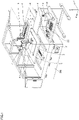
- Fig. 1 is a schematic perspective view of an application apparatus 200 according to an embodiment of the present invention.
- application apparatus 200 in a first embodiment of the present invention includes a base 12 arranged on a floor surface, an X-axis table 1, a Y-axis table 2, a Z-axis table 3, an application mechanism 4, an observation optical system 6, a CCD camera 7 connected to observation optical system 6, and a controller 11.
- Y-axis table 2 configured to be movable in a Y-axis direction in Fig. 1 is placed on an upper surface of base 12. Specifically, a guide portion is placed on a lower surface of Y-axis table 2 and is connected so as to be slidable along a guide rail placed on the upper surface of base 12. A ball screw is also connected to the lower surface of Y-axis table 2. By operating the ball screw with a driving member such as a motor, Y-axis table 2 can move along the guide rail (in the Y-axis direction).
- An upper surface portion of Y-axis table 2 is a mounting surface for mounting a substrate 5 which is an object to which an application material is applied.
- a gate-type construction placed so as to extend across the guide rail of Y-axis table 2 in an X-axis direction is provided on base 12.
- X-axis table 1 movable in the X-axis direction is mounted on this construction.
- X-axis table 1 is movable in the X-axis direction using, for example, a ball screw.
- Z-axis table 3 is mounted on a moving body of X-axis table 1, and application mechanism 4 and observation optical system 6 are mounted on Z-axis table 3.
- Application mechanism 4 and observation optical system 6 are movable in the X-axis direction together with Z-axis table 3.
- Application mechanism 4 is provided to apply an application material onto a surface (upper surface side) of substrate 5 to which the application material is applied, using an application needle provided in application mechanism 4.
- Observation optical system 6 is provided to observe an application position of substrate 5 to which the application material is applied.
- CCD camera 7 of observation optical system 6 converts an observed image to an electric signal.
- Z-axis table 3 supports application mechanism 4 and observation optical system 6 so as to be movable in a Z-axis direction.
- Controller 11 includes an operation panel 8, a monitor 9 and a control computer 10. Controller 11 controls X-axis table 1, Y-axis table 2, Z-axis table 3, application mechanism 4, and observation optical system 6. Operation panel 8 is used to input a command to control computer 10. Monitor 9 displays image data converted by CCD camera 7 of observation optical system 6 and output data from control computer 10.
- a drawing position of substrate 5 to which the application material is applied is moved to a position directly below observation optical system 6 using X-axis table 1 and Y-axis table 2, and a drawing start position is observed and checked using observation optical system 6, to determine the drawing start position. Then, the circuit pattern is drawn based on the determined drawing start position. Using X-axis table 1 and Y-axis table 2, substrate 5 is moved from the drawing start position, such that the drawing position is located directly below application mechanism 4. When the movement is completed, application mechanism 4 is driven to apply the liquid material. By continuously repeating this, the circuit pattern can be drawn.
- a relation between a moving-down end position of an application needle 24 and a focus position of observation optical system 6 is prestored, and at the time of drawing, using the Z-axis table, a position of an image focused by observation optical system 6 is moved to a height at which application needle 24 is in contact with substrate 5 with respect to the Z-axis direction, and then, the application material is applied.
- the focus position is checked in the process of drawing as needed and the position in the Z-axis direction is corrected, and then, the application material is applied.
- Adjustment of the focus position at this time may be made using a method for automatic focusing with image processing, or a method for using a laser sensor and the like to constantly detect the height position of the surface of substrate 5 to which the application material is applied and make a correction in real time.
- the substrate having the pattern formed thereon can be obtained.
- the substrate having no defect of the pattern can be obtained.
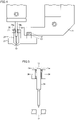
- Application mechanism 4 mentioned above will be described in more detail with reference to Figs. 2 and 4 .
- Application mechanism 4 fixed to Z-axis table 3 shown in Fig. 1 mainly includes a servo motor 41, a cam 43, a bearing 44, a cam coupling plate 45, a movable portion 46, an application needle holder 20, application needle 24 held in application needle holder 20, and an application material container 21.
- Servo motor 41 is placed such that a rotation shaft thereof extends in a direction along the Z-axis direction shown in Fig. 1 .
- Cam 43 is connected to the rotation shaft of servo motor 41.
- Cam 43 is rotatable about the rotation shaft of servo motor 41.
- Cam 43 includes a central portion connected to the rotation shaft of servo motor 41, and a flange portion connected to one end of the central portion.
- an upper surface (surface on the servo motor 41 side) of the flange portion is a cam surface 61.
- Cam surface 61 is formed to have an annular shape along an outer circumference of the central portion, and is formed to have a slope shape such that a distance from a bottom surface of the flange portion varies. Specifically, as shown in Fig.
- cam surface 61 includes an upper end flat region 62 having the longest distance from the bottom surface of the flange portion, a lower end flat region 63 spaced apart from upper end flat region 62 and having the shortest distance from the bottom surface of the flange portion, and a slope portion connecting upper end flat region 62 and lower end flat region 63.
- Fig. 3(B) is a development view of the flange portion including cam surface 61 arranged annularly so as to surround the central portion, when viewed from the side.
- Bearing 44 is arranged so as to be in contact with cam surface 61 of cam 43. As shown in Fig. 2(A) , bearing 44 is arranged in a specific direction (on the right side of servo motor 41) when viewed from cam 43, and when the rotation shaft of servo motor 41 rotates and cam 43 thereby rotates, the state of contact between bearing 44 and cam surface 61 is maintained.
- Cam coupling plate 45 is connected to bearing 44. The other end opposite to one end of cam coupling plate 45 connected to bearing 44 is fixed to movable portion 46.
- An application needle holder fixing portion 47 and an application needle holder housing portion 48 are connected to movable portion 46.
- Application needle holder 20 is housed in application needle holder housing portion 48.
- Application needle holder 20 includes application needle 24.
- Application needle 24 is arranged so as to protrude from application needle holder 20 on a lower surface (lower side opposite to the side where servo motor 41 is located) of application needle holder 20.
- Application material container 21 is arranged below application needle holder 20.
- Application needle 24 is held in application material container 21 in an inserted state.
- a fixing pin 52 is placed in movable portion 46.
- other fixing pin 51 is placed in a stand that holds servo motor 41.
- a spring 50 is placed so as to connect fixing pins 51 and 52.
- Spring 50 allows movable portion 46 to be under tensile force toward the application material container 21 side. This tensile force caused by spring 50 acts on bearing 44 through movable portion 46 and cam coupling plate 45. This tensile force caused by spring 50 allows bearing 44 to maintain a state of being pressed against cam surface 61 of cam 43.
- movable portion 46, application needle holder fixing portion 47 and application needle holder housing portion 48 are connected to a linear guide 49 placed on the above-described stand.
- Linear guide 49 is arranged so as to extend in the Z-axis direction. Therefore, movable portion 46, application needle holder fixing portion 47 and application needle holder housing portion 48 are movable along the Z-axis direction.
- Application material container 21 is fixed to a member 69.
- Fig. 4 is a cross-sectional view of conventional application material container 21 attached to member 69 when viewed from the side.
- An application material used when a pattern is drawn is housed in application material container 21.
- This application material is a high-viscosity metal conductive material and the like.
- a lower hole 72 is open in a bottom portion of application material container 21, and an upper hole 71 is open in an upper lid portion 29.
- Application needle 24 is provided so as to be movable along a straight line passing through lower hole 72 and upper hole 71.
- a linear motion mechanism of application mechanism 4 allows application needle 24 to reciprocate in the upward and downward direction.
- Lower hole 72 is set to have a size that allows application needle 24 to penetrate therethrough and a tip of application needle 24 to protrude downward, and a size that prevents the application material held in application material container 21 from dripping.
- Upper hole 71 has a size that allows application needle 24 to reciprocate in the upward and downward direction. That is, application needle 24 can move in the upward and downward direction, and thus, minute gaps 73a and 73b are formed between a wall of upper hole 71 and application needle 24.
- application needle 24 that can reciprocate in the upward and downward direction moves downward, application needle 24 protrudes from lower hole 72 toward the object to which the application material is applied, with the application material adhering to a surface of the tip of application needle 24.
- a fixing pin 93 of application material container 21 is bonded to a magnet 92 of member 69, and application material container 21 is thereby fixed.
- application needle 24 is not placed at a correct position in some cases.
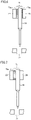
- Fig. 5 shows an example in which application needle 24 is placed at a correct position in the case of using conventional application material container 21.
- the tip of application needle 24 can protrude from lower hole 72.
- Fig. 6 shows an example in which application needle 24 is placed at a displaced position in the case of using conventional application material container 21.
- the position of application needle 24 is displaced, and thus, the tip of application needle 24 protrudes from lower hole 72 in a shifted state. This shift causes a change in an amount of application.
- Fig. 7 shows another example in which application needle 24 is placed at a displaced position in the case of using conventional application material container 21.
- application needle 24 is displaced to the right side, and thus, left gap 73a between the wall of upper hole 71 and application needle 24 becomes larger and no gap is provided between the wall of upper hole 71 and the right side.
- the force acts on a contact portion between the wall of upper hole 71 and application needle 24, and thus, an unbalanced load occurs.
- Fig. 8(A) is a cross-sectional view of application material container 21 in a first embodiment attached to member 69 when viewed from the side.
- Fig. 8(B) shows application material container 21 when viewed from the bottom.
- Application material container 21 in the first embodiment shown in Figs. 8(A) and (B) is different from conventional application material container 21 shown in Fig. 4 in that application material container 21 in the first embodiment is divided into a fixed portion 21b and a container portion 21a.
- Fixed portion 21b has fixing pin 93.
- Fixing pin 93 is bonded to magnet 92 of member 69, and fixed portion 21b is thereby fixed.
- a flange 80 is provided on a side surface of container portion 21a.
- An upper surface of fixed portion 21b is in contact with a lower surface of flange 80 to thereby support flange 80.
- Gaps 74a and 74b are provided between a portion lower than flange 80 on the side surface of container portion 21a and a side surface of fixed portion 21b.
- Container portion 21a can be inserted into fixed portion 21b so as to have gaps 74a and 74b therebetween. Even after fixing pin 93 of fixed portion 21b is bonded to magnet 92 of member 69, container portion 21a can move in the right and left direction within the range of gaps 74a and 74b. Therefore, even if gaps 73a and 73b between upper hole 71 of container portion 21a and application needle 24 are reduced in size, container portion 21a can be easily placed at a correct position with respect to application needle 24.
- Fig. 9 shows an example in which application needle 24 is placed at a displaced position in the case of using application material container 21 in the first embodiment.
- application needle 24 is placed at a position displaced to the left side, and thus, the tip of application needle 24 protrudes from a position shifted from lower hole 72.
- Fig. 10 shows a state in which container portion 21a has been moved from the state shown in Fig. 9 to the right side.
- left gap 74a becomes larger and right gap 74b becomes smaller.
- alignment is performed, and application needle 24 can protrude from a more central position of lower hole 72 without occurrence of an unbalanced load between application needle 24 and upper hole 71. As a result, the application material can be applied at a more stable amount of application.
- the position of container portion 21a is moved horizontally and the tip of application needle 24 is thereby adjusted so as to be located at the center of lower hole 72, and thus, the application material can be appropriately applied onto the surface of substrate 5.
- Movement by Z-axis table 3 may be first performed and then servo motor 41 may be driven, or the operation of Z-axis table 3 and the operation of servo motor 41 may be performed almost at the same time.
- Fig. 11(A) is a cross-sectional view of application material container 21 in a second embodiment attached to member 69 when viewed from the side.
- Fig. 11(B) shows application material container 21 when viewed from the bottom.
- a flange 81 is provided on the side surface of container portion 21a.
- the upper surface of fixed portion 21b is in contact with the lower surface of flange 80 to thereby support flange 80.
- Gaps 74a and 74b are provided between the portion lower than flange 80 on the side surface of container portion 21a and the side surface of fixed portion 21b.
- An upper surface of flange 81 on the side surface of container portion 21a is in contact with a lower surface of fixed portion 21b.
- Fixed portion 21b is sandwiched between flange 80 and flange 81, which makes it possible to prevent disconnection of container portion 21a from fixed portion 21b.
- the problem of occurrence of an unbalanced load caused by the force acting on the contact portion between the wall of upper hole 71 and application needle 24 can be avoided and the application material can be applied at a more stable amount of application, similarly to the first embodiment. Furthermore, in the present embodiment, container portion 21a is never disconnected from fixed portion 21b, and application material container 21 is easily attached and detached.
- the present invention is particularly advantageously applied to an application mechanism and an application apparatus for drawing a conductive pattern, correcting an open defect of a conductive pattern, forming and correcting a defect of a fine circuit pattern such as an RFID tag, applying a conductive adhesive, and the like.
Landscapes
- Coating Apparatus (AREA)
- Application Of Or Painting With Fluid Materials (AREA)
- Manufacturing Of Printed Wiring (AREA)
- Engineering & Computer Science (AREA)
- Manufacturing & Machinery (AREA)
Claims (3)
- Mécanisme d'application (4) comprenant :une aiguille d'application (24) ; etun contenant de matériau d'application (21) configuré pour accueillir et contenir un matériau d'application, le contenant de matériau d'application comportant une partie fixe (21b) et une partie contenant (21a), la partie fixe (21b) étant configurée pour pouvoir être fixée à un élément de fixation inclus dans le mécanisme d'application,la partie contenant étant pourvue, en ses parties supérieure et inférieure, de trous (71, 72) à travers lesquels passe l'aiguille d'application,une surface latérale de la partie contenant (21a) présentant un premier rebord (80),une surface inférieure du premier rebord (80) étant en contact avec une surface supérieure de la partie fixe (21b),caractérisé par :
un espace (74a, 74b) étant ménagé entre une partie au-dessous du premier rebord (80) sur la surface latérale de la partie contenant (21a) et une surface latérale de la partie fixe (21b), et la partie contenant (21a) pouvant se déplacer horizontalement sur une étendue de l'espace (74a, 74b). - Mécanisme d'application (4) selon la revendication 1, dans lequel :la surface latérale de la partie contenant (21a) présente un second rebord (81) sous le premier rebord (80), etune surface supérieure du second rebord (81) est en contact avec une surface inférieure de la partie fixe (21b), et la partie fixe est ainsi prise en sandwich entre le premier rebord (80) et le second rebord (81).
- Procédé de fabrication d'un objet sur lequel un matériau d'application est appliqué, à l'aide du mécanisme d'application (4) selon la revendication 1 ou 2.
Applications Claiming Priority (2)
| Application Number | Priority Date | Filing Date | Title |
|---|---|---|---|
| JP2016013003A JP6587945B2 (ja) | 2016-01-27 | 2016-01-27 | 塗布機構、塗布装置、被塗布対象物の製造方法、および基板の製造方法 |
| PCT/JP2017/001040 WO2017130741A1 (fr) | 2016-01-27 | 2017-01-13 | Mécanisme d'application, dispositif d'application, procédé de fabrication de support d'application, et procédé de fabrication de substrat |
Publications (4)
| Publication Number | Publication Date |
|---|---|
| EP3409375A1 EP3409375A1 (fr) | 2018-12-05 |
| EP3409375A4 EP3409375A4 (fr) | 2020-03-18 |
| EP3409375B1 true EP3409375B1 (fr) | 2022-04-06 |
| EP3409375B8 EP3409375B8 (fr) | 2022-09-28 |
Family
ID=59397861
Family Applications (1)
| Application Number | Title | Priority Date | Filing Date |
|---|---|---|---|
| EP17743972.6A Active EP3409375B8 (fr) | 2016-01-27 | 2017-01-13 | Mécanisme d'application et procédé de fabrication d'un objet sur lequel un matériau est appliqué |
Country Status (6)
| Country | Link |
|---|---|
| US (1) | US10751747B2 (fr) |
| EP (1) | EP3409375B8 (fr) |
| JP (1) | JP6587945B2 (fr) |
| CN (1) | CN108602085B (fr) |
| TW (1) | TWI712452B (fr) |
| WO (1) | WO2017130741A1 (fr) |
Families Citing this family (2)
| Publication number | Priority date | Publication date | Assignee | Title |
|---|---|---|---|---|
| TWI766345B (zh) | 2020-08-21 | 2022-06-01 | 研能科技股份有限公司 | 運動環境淨化裝置 |
| CN117023029B (zh) * | 2023-09-07 | 2024-02-27 | 广东百能家居有限公司 | 一种蜂窝板自动生产线及方法 |
Family Cites Families (17)
| Publication number | Priority date | Publication date | Assignee | Title |
|---|---|---|---|---|
| JPS482027Y1 (fr) * | 1968-07-11 | 1973-01-19 | ||
| JP3894776B2 (ja) * | 2001-11-09 | 2007-03-22 | 富士通メディアデバイス株式会社 | 吐出装置および吐出方法 |
| US6824023B2 (en) * | 2002-02-20 | 2004-11-30 | Lg. Philips Lcd Co., Ltd. | Liquid crystal dispensing apparatus |
| JP4162086B2 (ja) | 2003-08-26 | 2008-10-08 | Tdk株式会社 | 液体材料塗布方法 |
| JP4834981B2 (ja) * | 2004-12-03 | 2011-12-14 | 大日本印刷株式会社 | パターン形成体の製造方法 |
| JP4767708B2 (ja) * | 2005-03-28 | 2011-09-07 | Ntn株式会社 | 塗布ユニットおよびパターン修正装置 |
| JP4767567B2 (ja) | 2005-03-28 | 2011-09-07 | Ntn株式会社 | パターン修正装置 |
| JP4890024B2 (ja) | 2005-12-27 | 2012-03-07 | Ntn株式会社 | 塗布針固定方法と、それを用いた液状材料塗布機構および欠陥修正装置 |
| JP4719050B2 (ja) | 2006-03-30 | 2011-07-06 | Ntn株式会社 | パターン修正装置およびその塗布ユニット |
| JP4802027B2 (ja) * | 2006-03-30 | 2011-10-26 | Ntn株式会社 | パターン修正装置およびその塗布ユニット |
| US9162249B2 (en) * | 2008-10-01 | 2015-10-20 | Panasonic Intellectual Property Management Co., Ltd. | Paste dispenser for applying paste containing fillers using nozzle with pin and application method using the same |
| JP2013055286A (ja) | 2011-09-06 | 2013-03-21 | Ntn Corp | 液体塗布装置、パターン修正装置、微細パターン描画装置および液体塗布方法 |
| JP5779123B2 (ja) * | 2012-03-05 | 2015-09-16 | 富士フイルム株式会社 | パターン形成方法及びパターン形成基板の製造方法 |
| JP6019365B2 (ja) * | 2013-10-29 | 2016-11-02 | 兵神装備株式会社 | 吐出システムの製造方法 |
| JP6180283B2 (ja) * | 2013-11-06 | 2017-08-16 | 武蔵エンジニアリング株式会社 | 液体材料吐出装置および方法 |
| JP6452147B2 (ja) * | 2015-01-19 | 2019-01-16 | 武蔵エンジニアリング株式会社 | 液体材料吐出装置 |
| JP6749814B2 (ja) * | 2015-11-12 | 2020-09-02 | Ntn株式会社 | 高さ検出装置およびそれを搭載した塗布装置 |
-
2016
- 2016-01-27 JP JP2016013003A patent/JP6587945B2/ja active Active
-
2017
- 2017-01-13 WO PCT/JP2017/001040 patent/WO2017130741A1/fr not_active Ceased
- 2017-01-13 US US16/072,874 patent/US10751747B2/en active Active
- 2017-01-13 CN CN201780007891.5A patent/CN108602085B/zh active Active
- 2017-01-13 EP EP17743972.6A patent/EP3409375B8/fr active Active
- 2017-01-20 TW TW106102043A patent/TWI712452B/zh active
Also Published As
| Publication number | Publication date |
|---|---|
| WO2017130741A1 (fr) | 2017-08-03 |
| CN108602085B (zh) | 2020-10-13 |
| JP2017131826A (ja) | 2017-08-03 |
| US10751747B2 (en) | 2020-08-25 |
| CN108602085A (zh) | 2018-09-28 |
| JP6587945B2 (ja) | 2019-10-09 |
| US20190060948A1 (en) | 2019-02-28 |
| EP3409375A4 (fr) | 2020-03-18 |
| EP3409375B8 (fr) | 2022-09-28 |
| EP3409375A1 (fr) | 2018-12-05 |
| TW201738000A (zh) | 2017-11-01 |
| TWI712452B (zh) | 2020-12-11 |
Similar Documents
| Publication | Publication Date | Title |
|---|---|---|
| EP3381569B1 (fr) | Unité de revêtement, dispositif de revêtement, procédé de production d'un objet à revêtir et procédé de production d'un substrat | |
| CN101047090B (zh) | 图形修正装置及其涂布单元 | |
| JP6514047B2 (ja) | 塗布ユニットおよびそれを用いた塗布装置 | |
| CN105828958A (zh) | 涂布构件、涂布装置及涂布方法 | |
| JP6580874B2 (ja) | 液体塗布ユニットおよび液体塗布装置 | |
| CN105813765B (zh) | 涂布构件及涂布装置 | |
| EP3409375B1 (fr) | MÉCANISME D'APPLICATION ET PROCÉDÉ DE FABRICATION D'UN OBJET SUR
LEQUEL UN MATÉRIAU EST APPLIQUÉ | |
| WO2018155589A1 (fr) | Unité d'application de liquide et dispositif d'application de liquide | |
| JP6560108B2 (ja) | 塗布ユニット、塗布装置、被塗布対象物の製造方法および基板の製造方法 | |
| JP6460694B2 (ja) | 塗布方法および塗布装置 | |
| JP6794187B2 (ja) | 液体塗布ユニットおよび液体塗布装置 | |
| JP6745683B2 (ja) | 液体塗布ユニット、液体塗布装置および液体塗布方法 | |
| US20230083367A1 (en) | Liquid material application unit, liquid material application device, and liquid material application method | |
| JP2017094287A (ja) | 塗布ユニット、塗布装置、被塗布対象物の製造方法および基板の製造方法 | |
| US20220126573A1 (en) | Liquid application unit and liquid application apparatus | |
| JP2018130694A (ja) | 液体塗布ユニットおよび液体塗布装置 | |
| JP2018034122A (ja) | 液体塗布ユニットおよび液体塗布装置 | |
| JP2018034074A (ja) | 液体塗布ユニット、液体塗布装置、および液体塗布方法 | |
| JP2024121598A (ja) | 塗布針および塗布装置 | |
| WO2016204061A1 (fr) | Dispositif de recouvrement avec un matériau liquide |
Legal Events
| Date | Code | Title | Description |
|---|---|---|---|
| STAA | Information on the status of an ep patent application or granted ep patent |
Free format text: STATUS: THE INTERNATIONAL PUBLICATION HAS BEEN MADE |
|
| PUAI | Public reference made under article 153(3) epc to a published international application that has entered the european phase |
Free format text: ORIGINAL CODE: 0009012 |
|
| STAA | Information on the status of an ep patent application or granted ep patent |
Free format text: STATUS: REQUEST FOR EXAMINATION WAS MADE |
|
| 17P | Request for examination filed |
Effective date: 20180822 |
|
| AK | Designated contracting states |
Kind code of ref document: A1 Designated state(s): AL AT BE BG CH CY CZ DE DK EE ES FI FR GB GR HR HU IE IS IT LI LT LU LV MC MK MT NL NO PL PT RO RS SE SI SK SM TR |
|
| AX | Request for extension of the european patent |
Extension state: BA ME |
|
| DAV | Request for validation of the european patent (deleted) | ||
| DAX | Request for extension of the european patent (deleted) | ||
| A4 | Supplementary search report drawn up and despatched |
Effective date: 20200219 |
|
| RIC1 | Information provided on ipc code assigned before grant |
Ipc: B05C 11/10 20060101ALN20200213BHEP Ipc: B05D 1/28 20060101ALI20200213BHEP Ipc: B05C 1/02 20060101AFI20200213BHEP Ipc: H05K 3/12 20060101ALI20200213BHEP Ipc: H05K 3/10 20060101ALI20200213BHEP |
|
| GRAP | Despatch of communication of intention to grant a patent |
Free format text: ORIGINAL CODE: EPIDOSNIGR1 |
|
| STAA | Information on the status of an ep patent application or granted ep patent |
Free format text: STATUS: GRANT OF PATENT IS INTENDED |
|
| RIC1 | Information provided on ipc code assigned before grant |
Ipc: B05C 11/10 20060101ALN20211005BHEP Ipc: H01J 11/00 20120101ALI20211005BHEP Ipc: G02F 1/13 20060101ALI20211005BHEP Ipc: G02B 5/20 20060101ALI20211005BHEP Ipc: H05K 3/12 20060101ALI20211005BHEP Ipc: H05K 3/10 20060101ALI20211005BHEP Ipc: B05D 1/28 20060101ALI20211005BHEP Ipc: B05C 1/02 20060101AFI20211005BHEP |
|
| INTG | Intention to grant announced |
Effective date: 20211026 |
|
| GRAS | Grant fee paid |
Free format text: ORIGINAL CODE: EPIDOSNIGR3 |
|
| GRAA | (expected) grant |
Free format text: ORIGINAL CODE: 0009210 |
|
| STAA | Information on the status of an ep patent application or granted ep patent |
Free format text: STATUS: THE PATENT HAS BEEN GRANTED |
|
| AK | Designated contracting states |
Kind code of ref document: B1 Designated state(s): AL AT BE BG CH CY CZ DE DK EE ES FI FR GB GR HR HU IE IS IT LI LT LU LV MC MK MT NL NO PL PT RO RS SE SI SK SM TR |
|
| REG | Reference to a national code |
Ref country code: GB Ref legal event code: FG4D |
|
| REG | Reference to a national code |
Ref country code: CH Ref legal event code: EP |
|
| REG | Reference to a national code |
Ref country code: AT Ref legal event code: REF Ref document number: 1480809 Country of ref document: AT Kind code of ref document: T Effective date: 20220415 |
|
| REG | Reference to a national code |
Ref country code: DE Ref legal event code: R096 Ref document number: 602017055562 Country of ref document: DE |
|
| REG | Reference to a national code |
Ref country code: IE Ref legal event code: FG4D |
|
| REG | Reference to a national code |
Ref country code: CH Ref legal event code: PK Free format text: BERICHTIGUNG B8 |
|
| REG | Reference to a national code |
Ref country code: LT Ref legal event code: MG9D |
|
| REG | Reference to a national code |
Ref country code: NL Ref legal event code: MP Effective date: 20220406 |
|
| REG | Reference to a national code |
Ref country code: CH Ref legal event code: PK Free format text: BERICHTIGUNG B8 Ref country code: CH Ref legal event code: PK Free format text: TITEL |
|
| REG | Reference to a national code |
Ref country code: AT Ref legal event code: MK05 Ref document number: 1480809 Country of ref document: AT Kind code of ref document: T Effective date: 20220406 |
|
| PG25 | Lapsed in a contracting state [announced via postgrant information from national office to epo] |
Ref country code: NL Free format text: LAPSE BECAUSE OF FAILURE TO SUBMIT A TRANSLATION OF THE DESCRIPTION OR TO PAY THE FEE WITHIN THE PRESCRIBED TIME-LIMIT Effective date: 20220406 |
|
| PG25 | Lapsed in a contracting state [announced via postgrant information from national office to epo] |
Ref country code: SE Free format text: LAPSE BECAUSE OF FAILURE TO SUBMIT A TRANSLATION OF THE DESCRIPTION OR TO PAY THE FEE WITHIN THE PRESCRIBED TIME-LIMIT Effective date: 20220406 Ref country code: PT Free format text: LAPSE BECAUSE OF FAILURE TO SUBMIT A TRANSLATION OF THE DESCRIPTION OR TO PAY THE FEE WITHIN THE PRESCRIBED TIME-LIMIT Effective date: 20220808 Ref country code: NO Free format text: LAPSE BECAUSE OF FAILURE TO SUBMIT A TRANSLATION OF THE DESCRIPTION OR TO PAY THE FEE WITHIN THE PRESCRIBED TIME-LIMIT Effective date: 20220706 Ref country code: LT Free format text: LAPSE BECAUSE OF FAILURE TO SUBMIT A TRANSLATION OF THE DESCRIPTION OR TO PAY THE FEE WITHIN THE PRESCRIBED TIME-LIMIT Effective date: 20220406 Ref country code: HR Free format text: LAPSE BECAUSE OF FAILURE TO SUBMIT A TRANSLATION OF THE DESCRIPTION OR TO PAY THE FEE WITHIN THE PRESCRIBED TIME-LIMIT Effective date: 20220406 Ref country code: GR Free format text: LAPSE BECAUSE OF FAILURE TO SUBMIT A TRANSLATION OF THE DESCRIPTION OR TO PAY THE FEE WITHIN THE PRESCRIBED TIME-LIMIT Effective date: 20220707 Ref country code: FI Free format text: LAPSE BECAUSE OF FAILURE TO SUBMIT A TRANSLATION OF THE DESCRIPTION OR TO PAY THE FEE WITHIN THE PRESCRIBED TIME-LIMIT Effective date: 20220406 Ref country code: ES Free format text: LAPSE BECAUSE OF FAILURE TO SUBMIT A TRANSLATION OF THE DESCRIPTION OR TO PAY THE FEE WITHIN THE PRESCRIBED TIME-LIMIT Effective date: 20220406 Ref country code: BG Free format text: LAPSE BECAUSE OF FAILURE TO SUBMIT A TRANSLATION OF THE DESCRIPTION OR TO PAY THE FEE WITHIN THE PRESCRIBED TIME-LIMIT Effective date: 20220706 Ref country code: AT Free format text: LAPSE BECAUSE OF FAILURE TO SUBMIT A TRANSLATION OF THE DESCRIPTION OR TO PAY THE FEE WITHIN THE PRESCRIBED TIME-LIMIT Effective date: 20220406 |
|
| PG25 | Lapsed in a contracting state [announced via postgrant information from national office to epo] |
Ref country code: RS Free format text: LAPSE BECAUSE OF FAILURE TO SUBMIT A TRANSLATION OF THE DESCRIPTION OR TO PAY THE FEE WITHIN THE PRESCRIBED TIME-LIMIT Effective date: 20220406 Ref country code: PL Free format text: LAPSE BECAUSE OF FAILURE TO SUBMIT A TRANSLATION OF THE DESCRIPTION OR TO PAY THE FEE WITHIN THE PRESCRIBED TIME-LIMIT Effective date: 20220406 Ref country code: LV Free format text: LAPSE BECAUSE OF FAILURE TO SUBMIT A TRANSLATION OF THE DESCRIPTION OR TO PAY THE FEE WITHIN THE PRESCRIBED TIME-LIMIT Effective date: 20220406 Ref country code: IS Free format text: LAPSE BECAUSE OF FAILURE TO SUBMIT A TRANSLATION OF THE DESCRIPTION OR TO PAY THE FEE WITHIN THE PRESCRIBED TIME-LIMIT Effective date: 20220806 |
|
| REG | Reference to a national code |
Ref country code: DE Ref legal event code: R097 Ref document number: 602017055562 Country of ref document: DE |
|
| PG25 | Lapsed in a contracting state [announced via postgrant information from national office to epo] |
Ref country code: SM Free format text: LAPSE BECAUSE OF FAILURE TO SUBMIT A TRANSLATION OF THE DESCRIPTION OR TO PAY THE FEE WITHIN THE PRESCRIBED TIME-LIMIT Effective date: 20220406 Ref country code: SK Free format text: LAPSE BECAUSE OF FAILURE TO SUBMIT A TRANSLATION OF THE DESCRIPTION OR TO PAY THE FEE WITHIN THE PRESCRIBED TIME-LIMIT Effective date: 20220406 Ref country code: RO Free format text: LAPSE BECAUSE OF FAILURE TO SUBMIT A TRANSLATION OF THE DESCRIPTION OR TO PAY THE FEE WITHIN THE PRESCRIBED TIME-LIMIT Effective date: 20220406 Ref country code: EE Free format text: LAPSE BECAUSE OF FAILURE TO SUBMIT A TRANSLATION OF THE DESCRIPTION OR TO PAY THE FEE WITHIN THE PRESCRIBED TIME-LIMIT Effective date: 20220406 Ref country code: DK Free format text: LAPSE BECAUSE OF FAILURE TO SUBMIT A TRANSLATION OF THE DESCRIPTION OR TO PAY THE FEE WITHIN THE PRESCRIBED TIME-LIMIT Effective date: 20220406 Ref country code: CZ Free format text: LAPSE BECAUSE OF FAILURE TO SUBMIT A TRANSLATION OF THE DESCRIPTION OR TO PAY THE FEE WITHIN THE PRESCRIBED TIME-LIMIT Effective date: 20220406 |
|
| PLBE | No opposition filed within time limit |
Free format text: ORIGINAL CODE: 0009261 |
|
| STAA | Information on the status of an ep patent application or granted ep patent |
Free format text: STATUS: NO OPPOSITION FILED WITHIN TIME LIMIT |
|
| 26N | No opposition filed |
Effective date: 20230110 |
|
| PG25 | Lapsed in a contracting state [announced via postgrant information from national office to epo] |
Ref country code: AL Free format text: LAPSE BECAUSE OF FAILURE TO SUBMIT A TRANSLATION OF THE DESCRIPTION OR TO PAY THE FEE WITHIN THE PRESCRIBED TIME-LIMIT Effective date: 20220406 |
|
| PG25 | Lapsed in a contracting state [announced via postgrant information from national office to epo] |
Ref country code: SI Free format text: LAPSE BECAUSE OF FAILURE TO SUBMIT A TRANSLATION OF THE DESCRIPTION OR TO PAY THE FEE WITHIN THE PRESCRIBED TIME-LIMIT Effective date: 20220406 |
|
| REG | Reference to a national code |
Ref country code: DE Ref legal event code: R119 Ref document number: 602017055562 Country of ref document: DE |
|
| REG | Reference to a national code |
Ref country code: CH Ref legal event code: PL |
|
| GBPC | Gb: european patent ceased through non-payment of renewal fee |
Effective date: 20230113 |
|
| PG25 | Lapsed in a contracting state [announced via postgrant information from national office to epo] |
Ref country code: LU Free format text: LAPSE BECAUSE OF NON-PAYMENT OF DUE FEES Effective date: 20230113 |
|
| REG | Reference to a national code |
Ref country code: BE Ref legal event code: MM Effective date: 20230131 |
|
| PG25 | Lapsed in a contracting state [announced via postgrant information from national office to epo] |
Ref country code: LI Free format text: LAPSE BECAUSE OF NON-PAYMENT OF DUE FEES Effective date: 20230131 Ref country code: GB Free format text: LAPSE BECAUSE OF NON-PAYMENT OF DUE FEES Effective date: 20230113 Ref country code: DE Free format text: LAPSE BECAUSE OF NON-PAYMENT OF DUE FEES Effective date: 20230801 Ref country code: CH Free format text: LAPSE BECAUSE OF NON-PAYMENT OF DUE FEES Effective date: 20230131 |
|
| PG25 | Lapsed in a contracting state [announced via postgrant information from national office to epo] |
Ref country code: BE Free format text: LAPSE BECAUSE OF NON-PAYMENT OF DUE FEES Effective date: 20230131 |
|
| PG25 | Lapsed in a contracting state [announced via postgrant information from national office to epo] |
Ref country code: IT Free format text: LAPSE BECAUSE OF FAILURE TO SUBMIT A TRANSLATION OF THE DESCRIPTION OR TO PAY THE FEE WITHIN THE PRESCRIBED TIME-LIMIT Effective date: 20220406 Ref country code: IE Free format text: LAPSE BECAUSE OF NON-PAYMENT OF DUE FEES Effective date: 20230113 |
|
| PG25 | Lapsed in a contracting state [announced via postgrant information from national office to epo] |
Ref country code: MC Free format text: LAPSE BECAUSE OF FAILURE TO SUBMIT A TRANSLATION OF THE DESCRIPTION OR TO PAY THE FEE WITHIN THE PRESCRIBED TIME-LIMIT Effective date: 20220406 |
|
| PG25 | Lapsed in a contracting state [announced via postgrant information from national office to epo] |
Ref country code: MC Free format text: LAPSE BECAUSE OF FAILURE TO SUBMIT A TRANSLATION OF THE DESCRIPTION OR TO PAY THE FEE WITHIN THE PRESCRIBED TIME-LIMIT Effective date: 20220406 |
|
| PG25 | Lapsed in a contracting state [announced via postgrant information from national office to epo] |
Ref country code: BG Free format text: LAPSE BECAUSE OF FAILURE TO SUBMIT A TRANSLATION OF THE DESCRIPTION OR TO PAY THE FEE WITHIN THE PRESCRIBED TIME-LIMIT Effective date: 20220406 |
|
| PG25 | Lapsed in a contracting state [announced via postgrant information from national office to epo] |
Ref country code: BG Free format text: LAPSE BECAUSE OF FAILURE TO SUBMIT A TRANSLATION OF THE DESCRIPTION OR TO PAY THE FEE WITHIN THE PRESCRIBED TIME-LIMIT Effective date: 20220406 |
|
| PG25 | Lapsed in a contracting state [announced via postgrant information from national office to epo] |
Ref country code: CY Free format text: LAPSE BECAUSE OF FAILURE TO SUBMIT A TRANSLATION OF THE DESCRIPTION OR TO PAY THE FEE WITHIN THE PRESCRIBED TIME-LIMIT; INVALID AB INITIO Effective date: 20170113 |
|
| PG25 | Lapsed in a contracting state [announced via postgrant information from national office to epo] |
Ref country code: HU Free format text: LAPSE BECAUSE OF FAILURE TO SUBMIT A TRANSLATION OF THE DESCRIPTION OR TO PAY THE FEE WITHIN THE PRESCRIBED TIME-LIMIT; INVALID AB INITIO Effective date: 20170113 |
|
| PG25 | Lapsed in a contracting state [announced via postgrant information from national office to epo] |
Ref country code: TR Free format text: LAPSE BECAUSE OF FAILURE TO SUBMIT A TRANSLATION OF THE DESCRIPTION OR TO PAY THE FEE WITHIN THE PRESCRIBED TIME-LIMIT Effective date: 20220406 |
|
| PGFP | Annual fee paid to national office [announced via postgrant information from national office to epo] |
Ref country code: FR Payment date: 20251128 Year of fee payment: 10 |