EP3409588B1 - Agencement de bus électrique pour systèmes de protection contre la glace - Google Patents
Agencement de bus électrique pour systèmes de protection contre la glace Download PDFInfo
- Publication number
- EP3409588B1 EP3409588B1 EP17179897.8A EP17179897A EP3409588B1 EP 3409588 B1 EP3409588 B1 EP 3409588B1 EP 17179897 A EP17179897 A EP 17179897A EP 3409588 B1 EP3409588 B1 EP 3409588B1
- Authority
- EP
- European Patent Office
- Prior art keywords
- barrier layer
- blade
- wing
- bus bar
- ground
- Prior art date
- Legal status (The legal status is an assumption and is not a legal conclusion. Google has not performed a legal analysis and makes no representation as to the accuracy of the status listed.)
- Active
Links
Images




Classifications
-
- B—PERFORMING OPERATIONS; TRANSPORTING
- B64—AIRCRAFT; AVIATION; COSMONAUTICS
- B64D—EQUIPMENT FOR FITTING IN OR TO AIRCRAFT; FLIGHT SUITS; PARACHUTES; ARRANGEMENT OR MOUNTING OF POWER PLANTS OR PROPULSION TRANSMISSIONS IN AIRCRAFT
- B64D15/00—De-icing or preventing icing on exterior surfaces of aircraft
- B64D15/12—De-icing or preventing icing on exterior surfaces of aircraft by electric heating
-
- B—PERFORMING OPERATIONS; TRANSPORTING
- B64—AIRCRAFT; AVIATION; COSMONAUTICS
- B64C—AEROPLANES; HELICOPTERS
- B64C27/00—Rotorcraft; Rotors peculiar thereto
- B64C27/32—Rotors
- B64C27/46—Blades
- B64C27/463—Blade tips
-
- B—PERFORMING OPERATIONS; TRANSPORTING
- B64—AIRCRAFT; AVIATION; COSMONAUTICS
- B64C—AEROPLANES; HELICOPTERS
- B64C27/00—Rotorcraft; Rotors peculiar thereto
- B64C27/32—Rotors
- B64C27/46—Blades
- B64C27/467—Aerodynamic features
-
- F—MECHANICAL ENGINEERING; LIGHTING; HEATING; WEAPONS; BLASTING
- F03—MACHINES OR ENGINES FOR LIQUIDS; WIND, SPRING, OR WEIGHT MOTORS; PRODUCING MECHANICAL POWER OR A REACTIVE PROPULSIVE THRUST, NOT OTHERWISE PROVIDED FOR
- F03D—WIND MOTORS
- F03D80/00—Details, components or accessories not provided for in groups F03D1/00 - F03D17/00
- F03D80/40—Ice detection; De-icing means
-
- H—ELECTRICITY
- H05—ELECTRIC TECHNIQUES NOT OTHERWISE PROVIDED FOR
- H05B—ELECTRIC HEATING; ELECTRIC LIGHT SOURCES NOT OTHERWISE PROVIDED FOR; CIRCUIT ARRANGEMENTS FOR ELECTRIC LIGHT SOURCES, IN GENERAL
- H05B3/00—Ohmic-resistance heating
- H05B3/0004—Devices wherein the heating current flows through the material to be heated
-
- F—MECHANICAL ENGINEERING; LIGHTING; HEATING; WEAPONS; BLASTING
- F01—MACHINES OR ENGINES IN GENERAL; ENGINE PLANTS IN GENERAL; STEAM ENGINES
- F01D—NON-POSITIVE DISPLACEMENT MACHINES OR ENGINES, e.g. STEAM TURBINES
- F01D25/00—Component parts, details, or accessories, not provided for in, or of interest apart from, other groups
- F01D25/02—De-icing means for engines having icing phenomena
-
- F—MECHANICAL ENGINEERING; LIGHTING; HEATING; WEAPONS; BLASTING
- F03—MACHINES OR ENGINES FOR LIQUIDS; WIND, SPRING, OR WEIGHT MOTORS; PRODUCING MECHANICAL POWER OR A REACTIVE PROPULSIVE THRUST, NOT OTHERWISE PROVIDED FOR
- F03D—WIND MOTORS
- F03D1/00—Wind motors with rotation axis substantially parallel to the air flow entering the rotor
- F03D1/06—Rotors
- F03D1/065—Rotors characterised by their construction elements
- F03D1/0675—Rotors characterised by their construction elements of the blades
-
- F—MECHANICAL ENGINEERING; LIGHTING; HEATING; WEAPONS; BLASTING
- F05—INDEXING SCHEMES RELATING TO ENGINES OR PUMPS IN VARIOUS SUBCLASSES OF CLASSES F01-F04
- F05D—INDEXING SCHEME FOR ASPECTS RELATING TO NON-POSITIVE-DISPLACEMENT MACHINES OR ENGINES, GAS-TURBINES OR JET-PROPULSION PLANTS
- F05D2220/00—Application
- F05D2220/30—Application in turbines
- F05D2220/36—Application in turbines specially adapted for the fan of turbofan engines
-
- H—ELECTRICITY
- H05—ELECTRIC TECHNIQUES NOT OTHERWISE PROVIDED FOR
- H05B—ELECTRIC HEATING; ELECTRIC LIGHT SOURCES NOT OTHERWISE PROVIDED FOR; CIRCUIT ARRANGEMENTS FOR ELECTRIC LIGHT SOURCES, IN GENERAL
- H05B2203/00—Aspects relating to Ohmic resistive heating covered by group H05B3/00
- H05B2203/011—Heaters using laterally extending conductive material as connecting means
-
- H—ELECTRICITY
- H05—ELECTRIC TECHNIQUES NOT OTHERWISE PROVIDED FOR
- H05B—ELECTRIC HEATING; ELECTRIC LIGHT SOURCES NOT OTHERWISE PROVIDED FOR; CIRCUIT ARRANGEMENTS FOR ELECTRIC LIGHT SOURCES, IN GENERAL
- H05B2214/00—Aspects relating to resistive heating, induction heating and heating using microwaves, covered by groups H05B3/00, H05B6/00
- H05B2214/02—Heaters specially designed for de-icing or protection against icing
Definitions
- the present invention relates in general to the field of ice protection technology, and more particularly, to electrical bus arrangements in ice protection systems
- CA2741154 describes an aircraft heating system wherein the heater includes a haven constructed from dielectric layers, conductive lanes, bus bars, and strips. Facade sections of the layers and the lanes form the primary heating surface. The strips, along with sections of the layers/lanes, form havens for harbor sections of the bus bars.
- US2552075 describes heating devices for airplanes to prevent ice formation, for example on wings or propellers.
- the devices comprise a plurality of resistance wires.
- EP2873618 describes an ice protection heater for an aircraft component.
- the ice protection heater includes a woven fabric sheet comprising a plurality of warp and fill threads. At least some of the warp or fill threads are electrically conductive.
- the woven fabric sheet may include discontinuities in form of holes or slits whereby a desired electrical resistance may be obtained.
- US2205543 describes a heating surface for defrosting airplanes including a continuous resistive heating layer.
- a blade or a wing having a leading edge and comprising a heating element assembly for the blade or wing is set out in claim 1.
- the electrical lead of each electrical bus bar is J-shaped, L-shaped or has an enlarged end forming a contact pad; and each ground lead of the ground bus bar is J-shaped, L-shaped or has an enlarged end forming a contact pad.
- the first lead and second lead of each heating element is J-shaped, L-shaped or has an enlarged end forming a contact pad.
- the assembly further comprises an adhesive layer disposed on the one or more electrical bus bars, the ground bus bar, or the one or more heating elements.
- the first barrier layer, the second barrier layer, or the third barrier layer comprise a coating or a sleeve. In some aspects, the first barrier layer and the third barrier layer substantially encapsulate the one or more electrical bus bars, the ground bus bar, the second barrier layer and the one or more heating elements. In some aspects, the assembly further comprises a nose guard or protective layer disposed on a portion of the adhesion layer proximate to the leading edge. In some aspects, the assembly further comprises a controller electrically connected to the one or more electrical bus bars that operates and monitors the one or more heating elements.
- the blade is part of a propeller, a proprotor, a rotor or a wind turbine; or the wing is part of a fixed-wing aircraft, a tilt-rotor aircraft or a rotorcraft.
- a method for fabricating a leading edge assembly of a blade or wing is set out in claim 3.
- the electrical lead of each electrical bus bar is J-shaped, L-shaped or has an enlarged end forming a contact pad; and each ground lead of the ground bus bar is J-shaped, L-shaped or has an enlarged end forming a contact pad.
- the first lead and second lead of each heating element is J-shaped, L-shaped or has an enlarged end forming a contact pad.
- the method further comprises placing an adhesive layer on the one or more electrical bus bars, the ground bus bar, or the one or more heating elements.
- the first barrier layer, the second barrier layer, or the third barrier layer comprise a coating or a sleeve. In some aspects, the first barrier layer and the third barrier layer substantially encapsulate the one or more electrical bus bars, the ground bus bar, the second barrier layer and the one or more heating elements. In some aspects, the method further comprises placing a nose guard or protective layer on a portion of the adhesion layer proximate to the leading edge. In some aspects, the method further comprises curing the leading edge assembly.
- a method for controlling a heating system for a blade or wing is also disclosed.
- An aircraft comprising a heating element assembly is also disclosed, the aircraft comprising a fuselage; a blade or wing coupled to the fuselage, the blade or wing comprising the heating element.
- the embodiments of the invention disclosed herein can avoid the highest strains on a blade or wing by locating the electrical bus bars near the leading edge. To do this without affecting the heating performance of the conductive elements, the bus bars are located directly underneath the elements with a barrier layer between the two to prevent electrical failure.
- the embodiments disclosed herein may use a broader range of materials and geometries for bus bar design, which opens up more possibilities of ice protection solutions with fewer solder joints than are typically used in existing systems or no solder joints.
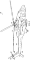
- FIG. 1 shows a helicopter 100 in accordance with a particular embodiment of the present application.
- helicopter 100 having a fuselage 102 and a rotor system 104 carried thereon.
- a plurality of rotor blades 106 is operably associated with a rotor system 104 for creating flight.
- a tail boom 108 is depicted that further includes tail rotor 110.
- FIG. 2 shows a partial cross-section perspective view of helicopter 100 that includes additional detail of the present invention.
- Helicopter 100 further includes a rotor mast 112, which is connected to the main transmission 114.
- the main transmission 114 is connected to one or more accessory gear boxes 116.
- the main transmission is connected to an engine 120, which is engine compartment 118.
- a tail boom drive shaft 122 transmits mechanical rotation to the tail rotor gear box 124, which is connected via tail rotor drive shaft 126, via intermediate gear box 128.
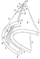
- FIG. 3 shows an exploded view of a leading edge of an inboard end of a blade or rotor according to one embodiment of the present invention.
- a composite heater blanket includes: conductive elements, electrical bus bars, and a ground bus bar that are sandwiched between several composite layers for insulation from other conductive materials that reside within a blade or wing, resulting in an ice protection solution without bus bars located in the highest-strained areas on the blade or wing.
- Heating element assembly 300 is added to outer sheath 302, which covers the leading edge of a rotor-blade spar and forms the leading edge blade contour of a blade or wing.
- Outer sheath 302 may comprise composite materials.
- First barrier layer 304 covers outer sheath 302 and the leading edge.
- First barrier layer 304 may be a coating or a sleeve, and it may comprise composite materials.
- One or more electrical bus bars 306 are disposed on first barrier layer 304 proximate to and substantially parallel with the leading edge, and each electrical bus bar has electrical lead 308.
- Each electrical lead 308 may extend chordwise away from electrical bus bars 306 and have a J-shape, an L-shape, an enlarged end forming a contact pad, or other shape as dictated by circumstances. Exemplary L-shaped electrical leads 308 are shown.
- Ground bus bar 310 which may be electrically connected to a common ground, is also disposed on first barrier layer 304 proximate to and substantially parallel with the leading edge, and ground bus bar 310 has one or more ground leads 312.
- Each ground lead 312 may extend chordwise away from ground bus bar 310 and may have a J-shape, an L-shape, an enlarged end forming a contact pad, or other shape as dictated by circumstances.
- FIG. 3 also shows that a second barrier layer 314 is disposed over electrical bus bars 306 and ground bus bar 310 such that all or part of electrical leads 308 and all or part of ground leads 312 are not covered by the second barrier layer 314.
- Second barrier layer 314 may be a coating or a sleeve, and it may comprise composite materials.
- One or more heating elements 316 are disposed on second barrier layer 314. Each heating element 316 has an electrical heating element lead, first lead 318, that is electrically connected to an electrical lead 308, and a ground heating element lead, second lead 320, that is electrically connected to a ground lead 312.
- Each first lead 318 and each second lead 320 may have a J-shape, an L-shape, an enlarged end forming a contact pad, or other shape as dictated by circumstances.
- Third barrier layer 322 is disposed over the one or more heating elements 316.
- Third barrier layer 322 may be a coating or a sleeve, and it may comprise composite materials.
- First barrier layer 304 and third barrier layer 322 may substantially encapsulate the one or more electrical bus bars 306, ground bus bar 310, second barrier layer 314, and the one or more heating elements 316.
- An adhesive layer 324 may be disposed on first barrier layer 304, the one or more electrical bus bars 306, ground bus bar 310, second barrier layer 314, one or more heating elements 316, or third barrier layer 322.
- Adhesion layer 326 may be disposed on third barrier layer 322.
- Adhesive layer 326, disposed on third barrier layer 322, is shown as a stipple pattern.
- a protective layer or a nose guard may be disposed on a portion of adhesion layer 326; exemplary protective layer 328 is shown. Protective layer 328 or nose guard may comprise composite materials.
- Fig. 4 shows a system block diagram of another embodiment of the present invention.
- Each heating element 316 of the one or more heating elements 316 is electrically connected to at least one of the one or more electrical bus bars 306 and ground bus bar 310 as described in connection with FIG. 3 .
- a controller 330 that operates and controls heating elements 316 in response to one or more monitored operational parameters to de-ice a blade or wing or prevent icing of the blade or wing may be electrically connected to heating elements 316, electrical bus bars 306, and ground bus bar 310, or, alternatively, directly to a common ground.
- FIG. 5 shows another exploded view of part of a leading edge of an inboard end of a blade or rotor according to another embodiment of the present invention, from a different viewpoint from that shown in FIG. 3 , and with some components omitted for clarity. Proceeding outward from outer sheath 302, first barrier layer 304, electrical bus bars 306, electrical leads 308, ground bus bar 310, ground lead 312, second barrier layer 314, heating elements 316, first leads 318, and second lead 320 are shown.
- FIG. 6 shows a perspective view of heating elements, electrical bus bars, electrical leads, a ground bus bar, and a first barrier layer according to an alternative embodiment of the present invention. This view omits other components for clarity.
- First barrier layer 304 is shown beneath electrical bus bars 306 and ground bus bar 310. Electrical bus bars 306 are shown with electrical leads 308. Heating elements 316 are shown overlaying electrical bus bars 306 and ground bus bar 310.
- FIG. 7 shows a perspective view of heating elements, electrical bus bars, electrical leads, and a ground bus bar according to an alternative embodiment of the present invention. This view makes easier an illustration of those components by omitting other components. Electrical bus bars 306 and ground bus bar 310 are shown. Electrical bus bars 306 are shown with electrical leads 308. Ground bus bar 310 is shown with ground lead 312. Heating elements 316 are shown overlaying electrical bus bars 306 and ground bus bar 310. First leads 318 and second lead 320 are also shown.
- FIG. 8 shows a connection of an electrical bus bar lead and a heating element according to an alternative embodiment of the present invention.
- Second barrier layer 314 is not shown.
- a part of electrical lead 308 is shown electrically connected to heating element 316 where electrical lead 308 is atop heating element 316.
- FIG. 9 shows an exploded view of electrical bus bars, a ground bus bar, and a first barrier layer according to an alternative embodiment of the present invention. This view shows first barrier layer 304, electrical bus bars 306, electrical leads 308, ground bus bar 310, and ground lead 312 from above the leading edge.
- FIG. 10A shows a view of electrical bus bars, electrical leads, and a first barrier layer according to an alternative embodiment of the present invention. This view shows first barrier layer 304, electrical bus bars 306, and electrical leads 308.
- FIG. 10B shows a view of the ground bus bar, ground leads, and a first barrier layer according to an embodiment of the present invention.
- the view is shows ground bus bar 310, ground leads 312, and first barrier layer 304.
- FIG. 11 shows a flattened plan view of electrical bus bars, a ground bus bar, and heating elements according to an alternative embodiment of the present invention. In this view, both the upper and lower surfaces are shown. Electrical bus bars 306 and ground bus bar 310 are shown with heating elements 316.
- FIG. 12 is a flowchart that illustrates a method for fabricating a leading edge assembly according to an alternative embodiment of the present invention.
- Method 1200 for fabricating a leading edge assembly of a blade or wing begins with step 1202, providing at least a portion of the blade or wing having a leading edge and an outer sheath 302.
- Method 1200 continues with step 1204, placing a first barrier layer 304 on an outer surface of the outer sheath 302 proximate to the leading edge.
- Method 1200 continues with step 1206, placing one or more electrical bus bars 306 and a ground bus bar 310 on the first barrier layer 304 proximate to and substantially parallel to the leading edge, each electrical bus bar having an electrical lead 308, and the ground bus bar 310 having one or more ground leads 312.
- Method 1200 continues with step 1208, placing a second barrier layer 314 over the one or more electrical bus bars 306 and the ground bus bar 310 such that all or part of the electrical leads 308 of the one or more electrical bus bars 306 and all or part of the ground leads 312 of the ground bus bar 310 are not covered by the second barrier layer 314.
- Method 1200 may also include placing an adhesive layer 324 on the first barrier layer 304, the one or more electrical bus bars 306, the ground bus bar 310, the second barrier layer 314, the one or more heating elements 316, or the third barrier layer 322; an exemplary step 1210, placing an adhesive layer 324 on the second barrier layer 314, is shown in FIG. 12 .
- method 1200 continues with step 1212, placing one or more heating elements 316 on the second barrier layer 314, each heating element 316 having a first lead 318 and a second lead 320.
- step 1214 electrically connecting the first lead 318 of each heating element 316 to the electrical lead 308 of one of the electrical bus bars 306.
- step 1216 electrically connecting the second lead 320 of each heating element 316 to one of the ground leads 312 of the ground bus bar 310.
- step 1218 placing a third barrier layer 322 over the one or more heating elements 316.
- step 1220 placing an adhesion layer 326 over the third barrier layer 322.
- method 1200 continues with step 1222, curing the leading edge assembly.
Landscapes
- Engineering & Computer Science (AREA)
- Aviation & Aerospace Engineering (AREA)
- Mechanical Engineering (AREA)
- Life Sciences & Earth Sciences (AREA)
- Sustainable Development (AREA)
- Sustainable Energy (AREA)
- Chemical & Material Sciences (AREA)
- Combustion & Propulsion (AREA)
- General Engineering & Computer Science (AREA)
- Physics & Mathematics (AREA)
- Fluid Mechanics (AREA)
- Control Of Resistance Heating (AREA)
- Surface Heating Bodies (AREA)
Claims (17)
- Pale ou aile ayant un bord d'attaque et comprenant un ensemble d'éléments chauffants (300) pour la pale ou l'aile, l'ensemble d'éléments chauffants comprenant :un ou plusieurs éléments chauffants (316) couvrant le bord d'attaque de la pale ou de l'aile, et caractérisée parune première couche barrière (304) couvrant le bord d'attaque de la pale ou de l'aile ;une couche adhésive (324) disposée sur la première couche barrière ;une ou plusieurs barres bus électriques (306) disposées sur la première couche barrière (304) à proximité du bord d'attaque et de manière sensiblement parallèle à celui-ci, chaque barre bus électrique (306) étant associée à un des éléments chauffants (316) et ayant un conducteur électrique (308) pour l'élément chauffant (316) qui s'étend dans le sens de la corde à partir de la barre bus électrique (306) et du bord d'attaque de la pale ou de l'aile ;une barre bus de terre (310) disposée sur la première couche barrière (304) à proximité du bord d'attaque et de manière sensiblement parallèle à celui-ci, la barre bus de terre (310) ayant un conducteur de terre (312) pour chaque élément chauffant (316) qui s'étend dans le sens de la corde à partir de la barre bus de terre (310) et du bord d'attaque de la pale ou de l'aile ;une deuxième couche barrière (314) disposée sur la barre ou les barres bus électrique(s) (306) et la barre bus de terre (310) de telle sorte que l'ensemble ou une partie des conducteurs électriques (308) de la barre ou des barres bus électrique(s) (306) et l'ensemble ou une partie des conducteurs de terre (312) de la barre bus de terre (310) ne sont pas couverts par la deuxième couche barrière (314) ;une couche adhésive (324) disposée sur la deuxième couche barrière (314) ;l'élément ou les éléments chauffant(s) (316) disposés sur la deuxième couche barrière (314) au-dessus de la barre ou des barres bus électrique(s) (306) et de la barre bus de terre (310), et chaque élément chauffant (316) ayant un premier conducteur (318) connecté électriquement au conducteur électrique (308) d'une des barres bus électriques (306) et un second conducteur (320) connecté électriquement à un des conducteurs de terre (312) de la barre bus de terre (310) ;une troisième couche barrière (322) disposée sur l'élément ou les éléments chauffant(s) (316) ;une couche adhésive (326) disposée sur la troisième couche barrière (322) ; etla première couche barrière (304), la deuxième couche barrière (314) et la troisième couche barrière (322) comprennent des couches composites pour l'isolation.
- Pale ou aile selon la revendication 1, l'ensemble d'éléments chauffants comprenant en outre :une gaine externe (302) disposée sur la pale ou l'aile ;la première couche barrière (304) disposée sur une partie de la gaine externe (302) ;un dispositif de commande (330) connecté électriquement à la barre ou aux barres bus électrique(s) (306) qui actionne et surveille l'élément ou les éléments chauffant(s) (316) ; etla barre bus de terre (310) est soit connectée électriquement au dispositif de commande (330), soit à une masse commune.
- Procédé de fabrication d'un ensemble bord d'attaque d'une pale ou aile ayant un ou plusieurs éléments chauffant(s) (316) couvrant un bord d'attaque de la pale ou de l'aile, le procédé comprenant :
la fourniture (1202) d'au moins une partie de la pale ou de l'aile ayant le bord d'attaque et une gaine externe (302) et caractérisé par :la mise en place (1204) d'une première couche barrière (304) sur une surface externe de la gaine externe (302) à proximité du bord d'attaque ;la mise en place d'une couche adhésive (324) sur la première couche barrière (304) ;la mise en place (1206) d'une ou de plusieurs barre(s) bus électrique(s) (306) et d'une barre bus de terre (310) sur la première couche barrière (304) à proximité du bord d'attaque et de manière sensiblement parallèle à celui-ci, chaque barre bus électrique (306) étant associée à un des éléments chauffants (316) et ayant un conducteur électrique (308) pour l'élément chauffant (316) qui s'étend dans le sens de la corde à partir de la barre bus électrique (306) et du bord d'attaque de la pale ou de l'aile, et la barre bus de terre (310) ayant un conducteur de terre (312) associé à chaque élément chauffant (316) qui s'étend dans le sens de la corde à partir de la barre bus de terre (310) et du bord d'attaque de la pale ou de l'aile ;la mise en place (1208) d'une deuxième couche barrière (314) sur la barre ou les barres bus électrique(s) (306) et la barre bus de terre (310) de telle sorte que l'ensemble ou une partie des conducteurs électriques (308) de la barre ou des barres bus (306) électrique(s) et que l'ensemble ou une partie des conducteurs de terre (312) de la barre bus de terre (310) ne sont pas couverts par la deuxième couche barrière (314) ;la mise en place d'une couche adhésive (324) sur la deuxième couche barrière (314) ;la mise en place (1212) de l'élément ou des éléments chauffant(s) (316) sur la deuxième couche barrière (314) au-dessus de la barre ou des barres bus électrique(s) (306) et de la barre bus de terre (310), chaque élément chauffant (316) ayant un premier conducteur (318) et un second conducteur (320) ;la connexion électrique (1214) du premier conducteur (318) de chaque élément chauffant au conducteur électrique (308) d'une des barres bus électriques (306) ;la connexion électrique (1216) du second conducteur (320) de chaque élément chauffant (316) à un des conducteurs de terre (312) de la barre bus de terre (310) ;la mise en place (1218) d'une troisième couche barrière (322) au-dessus de l'élément ou des éléments chauffant(s) (316) ; etla mise en place (1220) d'une couche d'adhésion (326) au-dessus de la troisième couche barrière (322) ;la liaison de la première couche barrière (304), de la barre ou des barres bus électrique(s) (306), de la barre bus de terre (310), de la deuxième couche barrière (314), de l'élément ou des éléments chauffant(s) (316), de la troisième couche barrière (322) et de la couche d'adhésion (326) les uns aux autres ; etla première couche barrière (304), la deuxième couche barrière (314) et la troisième couche barrière (322) comprennent des couches composites pour l'isolation. - Pale ou aile selon la revendication 1 ou la revendication 2, dans laquelle :le conducteur électrique (308) est en forme de J, en forme de L ou a une extrémité élargie formant un plot de contact ; etchaque conducteur de terre (312) est en forme de J, en forme de L ou a une extrémité élargie formant un plot de contact.
- Pale ou aile selon la revendication 1, 2 ou 4, dans laquelle le premier conducteur (318) et le second conducteur (320) sont en forme de J, en forme de L ou ont une extrémité élargie formant un plot de contact.
- Pale ou aile selon la revendication 1, 2, 4 ou 5, comprenant en outre une couche adhésive (324, 326) disposée sur la barre ou les barres bus électrique(s) (306), la barre bus de terre (310) ou l'élément ou les éléments chauffant(s) (316), ou la troisième couche barrière (322).
- Pale ou aile selon la revendication 1, 2, ou 4 à 6, dans laquelle la première couche barrière (304), la deuxième couche barrière (314) ou la troisième couche barrière (322) comprend un revêtement ou un manchon.
- Pale ou aile selon la revendication 1, 2, ou 4 à 7, dans laquelle la première couche barrière (304) et la troisième couche barrière (322) enveloppent sensiblement la barre ou les barres bus électrique(s) (306), la barre bus de terre (310), la deuxième couche barrière (314) et l'élément ou les éléments chauffant(s) (316).
- Pale ou aile selon la revendication 1, 2, ou 4 à 8, comprenant en outre un cache ou une couche de protection avant (328) disposé(e) sur une partie de la couche d'adhésion (326) à proximité du bord d'attaque.
- Hélice, hélirotor, rotor ou éolienne comprenant une pale selon la revendication 1 ou l'une quelconque des revendications précédentes ; ou
aéronef à voilure fixe, aéronef à rotor basculant ou giravion comprenant une aile selon la revendication 1, 2, ou 4 à 9. - Procédé selon la revendication 3, comprenant en outre le durcissement (1222) de l'ensemble bord d'attaque.
- Procédé selon la revendication 3 ou 11, comprenant en outre :la fourniture d'un dispositif de commande (330) connecté électriquement à la barre ou aux barres bus électrique(s) (306) qui actionne et surveille l'élément ou les éléments chauffant(s) (316) ;la surveillance d'un ou de plusieurs paramètre(s) opérationnel(s) ; etla commande de l'élément ou des éléments chauffant(s) (316) en réponse aux paramètres opérationnels au moyen du dispositif de commande (330) pour dégivrer la pale ou l'aile, ou empêcher le givrage de la pale ou de l'aile.
- Aéronef, comprenant :un fuselage ;une pale ou aile couplée au fuselage, la pale ou l'aile étant selon la revendication 1, 2 ou 4 à 9.
- Procédé selon la revendication 3, 11 ou 12, dans lequel :le conducteur électrique (308) est en forme de J, en forme de L ou a une extrémité élargie formant un plot de contact ;chaque conducteur de terre (312) est en forme de J, en forme de L ou a une extrémité élargie formant un plot de contact ; etle premier conducteur (318) et le second conducteur (320) sont en forme de J, en forme de L ou ont une extrémité élargie formant un plot de contact.
- Procédé selon la revendication 3, 11, 12 ou 14,
comprenant en outre une couche adhésive (324, 326) disposée sur la barre ou les barres bus électrique(s) (306), la barre bus de terre (310) ou l'élément ou les éléments chauffant(s) (316). - Procédé selon la revendication 3, 11, 12, 14 ou 15, dans lequel la première couche barrière (304), la deuxième couche barrière (314) ou la troisième couche barrière (322) comprend un revêtement ou une gaine.
- Procédé selon la revendication 3, 11, 12 ou 14 à 16, dans lequel la première couche barrière (304) et la troisième couche barrière (322) enveloppent sensiblement la barre ou les barres bus électrique(s) (306), la barre bus de terre (310), la deuxième couche barrière (314) et l'élément ou les éléments chauffant(s) (316).
Applications Claiming Priority (1)
| Application Number | Priority Date | Filing Date | Title |
|---|---|---|---|
| US15/608,385 US10787267B2 (en) | 2017-05-30 | 2017-05-30 | Electrical bus arrangement for ice protection systems |
Publications (2)
| Publication Number | Publication Date |
|---|---|
| EP3409588A1 EP3409588A1 (fr) | 2018-12-05 |
| EP3409588B1 true EP3409588B1 (fr) | 2019-09-11 |
Family
ID=59295024
Family Applications (1)
| Application Number | Title | Priority Date | Filing Date |
|---|---|---|---|
| EP17179897.8A Active EP3409588B1 (fr) | 2017-05-30 | 2017-07-05 | Agencement de bus électrique pour systèmes de protection contre la glace |
Country Status (3)
| Country | Link |
|---|---|
| US (1) | US10787267B2 (fr) |
| EP (1) | EP3409588B1 (fr) |
| CA (1) | CA3005501C (fr) |
Families Citing this family (14)
| Publication number | Priority date | Publication date | Assignee | Title |
|---|---|---|---|---|
| CA3027601C (fr) * | 2016-06-30 | 2020-12-15 | Vestas Wind Systems A/S | Pales d'eolienne avec barres omnibus |
| US10708979B2 (en) | 2016-10-07 | 2020-07-07 | De-Ice Technologies | Heating a bulk medium |
| US10457404B2 (en) * | 2017-01-31 | 2019-10-29 | Wan Tony Chee | Carbon nanotube anti-icing and de-icing means for aircraft |
| DE102017106998A1 (de) * | 2017-03-31 | 2018-10-04 | Airbus Operations Gmbh | Kabinenverkleidungselement für eine Flugzeugkabine und Spant für eine Flugzeugrumpfstruktur |
| US10787267B2 (en) | 2017-05-30 | 2020-09-29 | Bell Helicopter Textron Inc. | Electrical bus arrangement for ice protection systems |
| ES2952373T3 (es) | 2018-08-27 | 2023-10-31 | De Ice Tech Inc | Sistemas de deshielo |
| US11382178B2 (en) * | 2019-06-27 | 2022-07-05 | General Electric Company | System and method for heating an electrical bus in an electrical cabinet for cold startup and condensation/frost control |
| CA3149422A1 (fr) * | 2019-08-05 | 2021-02-11 | Vestas Wind Systems A/S | Pale d'eolienne avec element chauffant electrothermique |
| US11548648B2 (en) * | 2020-01-14 | 2023-01-10 | Goodrich Corporation | Robust power transmission |
| EP3869035B2 (fr) * | 2020-02-21 | 2026-02-11 | Siemens Gamesa Renewable Energy Innovation & Technology, S.L. | Pale pour un rotor d'éolienne et son procédé de fabrication |
| US11427336B2 (en) | 2020-03-25 | 2022-08-30 | Goodrich Corporation | High strain tolerant chord-wise ice protection layout |
| US11975850B2 (en) | 2020-04-07 | 2024-05-07 | Goodrich Corporation | Integrated busbar heater for ice protection systems |
| CN111749857B (zh) * | 2020-07-07 | 2023-08-15 | 湖南拓天节能控制技术股份有限公司 | 一种叶片气热除冰系统及其安装方法 |
| US20240417081A1 (en) * | 2023-06-16 | 2024-12-19 | Goodrich Corporation | Chordwise ice protection heater |
Family Cites Families (8)
| Publication number | Priority date | Publication date | Assignee | Title |
|---|---|---|---|---|
| US2205543A (en) | 1936-11-06 | 1940-06-25 | Rideau Jean Robert | Heating surface |
| US2552075A (en) | 1944-08-05 | 1951-05-08 | Catherine Van Daam | Heating device for airplanes |
| US4078107A (en) | 1976-06-28 | 1978-03-07 | Ppg Industries, Inc. | Lightweight window with heating circuit and anti-static circuit and a method for its preparation |
| US7291815B2 (en) | 2006-02-24 | 2007-11-06 | Goodrich Corporation | Composite ice protection heater and method of producing same |
| GB2477339B (en) * | 2010-01-29 | 2011-12-07 | Gkn Aerospace Services Ltd | Electrothermal heater mat |
| US10293947B2 (en) | 2010-05-27 | 2019-05-21 | Goodrich Corporation | Aircraft heating system |
| US10464680B2 (en) * | 2016-08-30 | 2019-11-05 | The Boeing Company | Electrically conductive materials for heating and deicing airfoils |
| US10787267B2 (en) | 2017-05-30 | 2020-09-29 | Bell Helicopter Textron Inc. | Electrical bus arrangement for ice protection systems |
-
2017
- 2017-05-30 US US15/608,385 patent/US10787267B2/en active Active
- 2017-07-05 EP EP17179897.8A patent/EP3409588B1/fr active Active
-
2018
- 2018-05-17 CA CA3005501A patent/CA3005501C/fr active Active
Non-Patent Citations (1)
| Title |
|---|
| None * |
Also Published As
| Publication number | Publication date |
|---|---|
| CA3005501C (fr) | 2020-07-07 |
| US20180346133A1 (en) | 2018-12-06 |
| CA3005501A1 (fr) | 2018-11-30 |
| EP3409588A1 (fr) | 2018-12-05 |
| US10787267B2 (en) | 2020-09-29 |
Similar Documents
| Publication | Publication Date | Title |
|---|---|---|
| EP3409588B1 (fr) | Agencement de bus électrique pour systèmes de protection contre la glace | |
| US11964768B2 (en) | Tailored rotor-blade ice-protection system | |
| EP3456635B1 (fr) | Système de protection contre la glace pour pale de rotor basculant | |
| US6227492B1 (en) | Redundant ice management system for aircraft | |
| US10252806B2 (en) | Electrothermal heater mat | |
| US5947418A (en) | Device for heating an aerofoil | |
| US8981266B2 (en) | Electrical apparatus | |
| US7078658B2 (en) | Heater mat made of electrically-conductive fibers | |
| US8807483B2 (en) | Electrothermal heater mat | |
| US8993940B2 (en) | Dielectric component with electrical connection | |
| US20120298803A1 (en) | Electrothermal heater | |
| US20180086470A1 (en) | Heating design for rotorcraft blade de-icing and anti-icing | |
| KR20080033155A (ko) | 열적 항빙 장치를 위한 변형 가능한 전도성/저항성 복합혼성 히터 | |
| EP2868575B1 (fr) | Pale de rotor avec interconnexions électriques | |
| US20240246683A1 (en) | Integrated busbar heater for ice protection systems | |
| US20170275006A1 (en) | Blade heater mat insulation | |
| US20180115127A1 (en) | Low-profile mechanical electrical interconnect |
Legal Events
| Date | Code | Title | Description |
|---|---|---|---|
| STAA | Information on the status of an ep patent application or granted ep patent |
Free format text: STATUS: EXAMINATION IS IN PROGRESS |
|
| PUAI | Public reference made under article 153(3) epc to a published international application that has entered the european phase |
Free format text: ORIGINAL CODE: 0009012 |
|
| 17P | Request for examination filed |
Effective date: 20170705 |
|
| AK | Designated contracting states |
Kind code of ref document: A1 Designated state(s): AL AT BE BG CH CY CZ DE DK EE ES FI FR GB GR HR HU IE IS IT LI LT LU LV MC MK MT NL NO PL PT RO RS SE SI SK SM TR |
|
| AX | Request for extension of the european patent |
Extension state: BA ME |
|
| GRAP | Despatch of communication of intention to grant a patent |
Free format text: ORIGINAL CODE: EPIDOSNIGR1 |
|
| STAA | Information on the status of an ep patent application or granted ep patent |
Free format text: STATUS: GRANT OF PATENT IS INTENDED |
|
| INTG | Intention to grant announced |
Effective date: 20190308 |
|
| GRAS | Grant fee paid |
Free format text: ORIGINAL CODE: EPIDOSNIGR3 |
|
| GRAJ | Information related to disapproval of communication of intention to grant by the applicant or resumption of examination proceedings by the epo deleted |
Free format text: ORIGINAL CODE: EPIDOSDIGR1 |
|
| GRAL | Information related to payment of fee for publishing/printing deleted |
Free format text: ORIGINAL CODE: EPIDOSDIGR3 |
|
| STAA | Information on the status of an ep patent application or granted ep patent |
Free format text: STATUS: EXAMINATION IS IN PROGRESS |
|
| INTC | Intention to grant announced (deleted) | ||
| GRAR | Information related to intention to grant a patent recorded |
Free format text: ORIGINAL CODE: EPIDOSNIGR71 |
|
| STAA | Information on the status of an ep patent application or granted ep patent |
Free format text: STATUS: GRANT OF PATENT IS INTENDED |
|
| INTG | Intention to grant announced |
Effective date: 20190702 |
|
| RIN1 | Information on inventor provided before grant (corrected) |
Inventor name: BURNETT, MICHAEL CHRIS Inventor name: FOSKEY, CHRISTOPHER E. Inventor name: PAULSON, JARED MARK |
|
| GRAA | (expected) grant |
Free format text: ORIGINAL CODE: 0009210 |
|
| STAA | Information on the status of an ep patent application or granted ep patent |
Free format text: STATUS: THE PATENT HAS BEEN GRANTED |
|
| AK | Designated contracting states |
Kind code of ref document: B1 Designated state(s): AL AT BE BG CH CY CZ DE DK EE ES FI FR GB GR HR HU IE IS IT LI LT LU LV MC MK MT NL NO PL PT RO RS SE SI SK SM TR |
|
| REG | Reference to a national code |
Ref country code: GB Ref legal event code: FG4D |
|
| REG | Reference to a national code |
Ref country code: CH Ref legal event code: EP |
|
| REG | Reference to a national code |
Ref country code: AT Ref legal event code: REF Ref document number: 1178140 Country of ref document: AT Kind code of ref document: T Effective date: 20190915 |
|
| REG | Reference to a national code |
Ref country code: DE Ref legal event code: R096 Ref document number: 602017006889 Country of ref document: DE Ref country code: IE Ref legal event code: FG4D |
|
| REG | Reference to a national code |
Ref country code: NL Ref legal event code: MP Effective date: 20190911 |
|
| REG | Reference to a national code |
Ref country code: LT Ref legal event code: MG4D |
|
| PG25 | Lapsed in a contracting state [announced via postgrant information from national office to epo] |
Ref country code: LT Free format text: LAPSE BECAUSE OF FAILURE TO SUBMIT A TRANSLATION OF THE DESCRIPTION OR TO PAY THE FEE WITHIN THE PRESCRIBED TIME-LIMIT Effective date: 20190911 Ref country code: SE Free format text: LAPSE BECAUSE OF FAILURE TO SUBMIT A TRANSLATION OF THE DESCRIPTION OR TO PAY THE FEE WITHIN THE PRESCRIBED TIME-LIMIT Effective date: 20190911 Ref country code: FI Free format text: LAPSE BECAUSE OF FAILURE TO SUBMIT A TRANSLATION OF THE DESCRIPTION OR TO PAY THE FEE WITHIN THE PRESCRIBED TIME-LIMIT Effective date: 20190911 Ref country code: NO Free format text: LAPSE BECAUSE OF FAILURE TO SUBMIT A TRANSLATION OF THE DESCRIPTION OR TO PAY THE FEE WITHIN THE PRESCRIBED TIME-LIMIT Effective date: 20191211 Ref country code: BG Free format text: LAPSE BECAUSE OF FAILURE TO SUBMIT A TRANSLATION OF THE DESCRIPTION OR TO PAY THE FEE WITHIN THE PRESCRIBED TIME-LIMIT Effective date: 20191211 Ref country code: HR Free format text: LAPSE BECAUSE OF FAILURE TO SUBMIT A TRANSLATION OF THE DESCRIPTION OR TO PAY THE FEE WITHIN THE PRESCRIBED TIME-LIMIT Effective date: 20190911 |
|
| PG25 | Lapsed in a contracting state [announced via postgrant information from national office to epo] |
Ref country code: RS Free format text: LAPSE BECAUSE OF FAILURE TO SUBMIT A TRANSLATION OF THE DESCRIPTION OR TO PAY THE FEE WITHIN THE PRESCRIBED TIME-LIMIT Effective date: 20190911 Ref country code: LV Free format text: LAPSE BECAUSE OF FAILURE TO SUBMIT A TRANSLATION OF THE DESCRIPTION OR TO PAY THE FEE WITHIN THE PRESCRIBED TIME-LIMIT Effective date: 20190911 Ref country code: GR Free format text: LAPSE BECAUSE OF FAILURE TO SUBMIT A TRANSLATION OF THE DESCRIPTION OR TO PAY THE FEE WITHIN THE PRESCRIBED TIME-LIMIT Effective date: 20191212 Ref country code: AL Free format text: LAPSE BECAUSE OF FAILURE TO SUBMIT A TRANSLATION OF THE DESCRIPTION OR TO PAY THE FEE WITHIN THE PRESCRIBED TIME-LIMIT Effective date: 20190911 Ref country code: ES Free format text: LAPSE BECAUSE OF FAILURE TO SUBMIT A TRANSLATION OF THE DESCRIPTION OR TO PAY THE FEE WITHIN THE PRESCRIBED TIME-LIMIT Effective date: 20190911 |
|
| REG | Reference to a national code |
Ref country code: AT Ref legal event code: MK05 Ref document number: 1178140 Country of ref document: AT Kind code of ref document: T Effective date: 20190911 |
|
| PG25 | Lapsed in a contracting state [announced via postgrant information from national office to epo] |
Ref country code: AT Free format text: LAPSE BECAUSE OF FAILURE TO SUBMIT A TRANSLATION OF THE DESCRIPTION OR TO PAY THE FEE WITHIN THE PRESCRIBED TIME-LIMIT Effective date: 20190911 Ref country code: PL Free format text: LAPSE BECAUSE OF FAILURE TO SUBMIT A TRANSLATION OF THE DESCRIPTION OR TO PAY THE FEE WITHIN THE PRESCRIBED TIME-LIMIT Effective date: 20190911 Ref country code: NL Free format text: LAPSE BECAUSE OF FAILURE TO SUBMIT A TRANSLATION OF THE DESCRIPTION OR TO PAY THE FEE WITHIN THE PRESCRIBED TIME-LIMIT Effective date: 20190911 Ref country code: RO Free format text: LAPSE BECAUSE OF FAILURE TO SUBMIT A TRANSLATION OF THE DESCRIPTION OR TO PAY THE FEE WITHIN THE PRESCRIBED TIME-LIMIT Effective date: 20190911 Ref country code: PT Free format text: LAPSE BECAUSE OF FAILURE TO SUBMIT A TRANSLATION OF THE DESCRIPTION OR TO PAY THE FEE WITHIN THE PRESCRIBED TIME-LIMIT Effective date: 20200113 Ref country code: EE Free format text: LAPSE BECAUSE OF FAILURE TO SUBMIT A TRANSLATION OF THE DESCRIPTION OR TO PAY THE FEE WITHIN THE PRESCRIBED TIME-LIMIT Effective date: 20190911 |
|
| PG25 | Lapsed in a contracting state [announced via postgrant information from national office to epo] |
Ref country code: SM Free format text: LAPSE BECAUSE OF FAILURE TO SUBMIT A TRANSLATION OF THE DESCRIPTION OR TO PAY THE FEE WITHIN THE PRESCRIBED TIME-LIMIT Effective date: 20190911 Ref country code: CZ Free format text: LAPSE BECAUSE OF FAILURE TO SUBMIT A TRANSLATION OF THE DESCRIPTION OR TO PAY THE FEE WITHIN THE PRESCRIBED TIME-LIMIT Effective date: 20190911 Ref country code: IS Free format text: LAPSE BECAUSE OF FAILURE TO SUBMIT A TRANSLATION OF THE DESCRIPTION OR TO PAY THE FEE WITHIN THE PRESCRIBED TIME-LIMIT Effective date: 20200224 Ref country code: SK Free format text: LAPSE BECAUSE OF FAILURE TO SUBMIT A TRANSLATION OF THE DESCRIPTION OR TO PAY THE FEE WITHIN THE PRESCRIBED TIME-LIMIT Effective date: 20190911 |
|
| REG | Reference to a national code |
Ref country code: DE Ref legal event code: R097 Ref document number: 602017006889 Country of ref document: DE |
|
| PLBE | No opposition filed within time limit |
Free format text: ORIGINAL CODE: 0009261 |
|
| STAA | Information on the status of an ep patent application or granted ep patent |
Free format text: STATUS: NO OPPOSITION FILED WITHIN TIME LIMIT |
|
| PG2D | Information on lapse in contracting state deleted |
Ref country code: IS |
|
| PG25 | Lapsed in a contracting state [announced via postgrant information from national office to epo] |
Ref country code: DK Free format text: LAPSE BECAUSE OF FAILURE TO SUBMIT A TRANSLATION OF THE DESCRIPTION OR TO PAY THE FEE WITHIN THE PRESCRIBED TIME-LIMIT Effective date: 20190911 Ref country code: IS Free format text: LAPSE BECAUSE OF FAILURE TO SUBMIT A TRANSLATION OF THE DESCRIPTION OR TO PAY THE FEE WITHIN THE PRESCRIBED TIME-LIMIT Effective date: 20200112 |
|
| 26N | No opposition filed |
Effective date: 20200615 |
|
| PG25 | Lapsed in a contracting state [announced via postgrant information from national office to epo] |
Ref country code: MC Free format text: LAPSE BECAUSE OF FAILURE TO SUBMIT A TRANSLATION OF THE DESCRIPTION OR TO PAY THE FEE WITHIN THE PRESCRIBED TIME-LIMIT Effective date: 20190911 |
|
| REG | Reference to a national code |
Ref country code: CH Ref legal event code: PL |
|
| REG | Reference to a national code |
Ref country code: BE Ref legal event code: MM Effective date: 20200731 |
|
| PG25 | Lapsed in a contracting state [announced via postgrant information from national office to epo] |
Ref country code: CH Free format text: LAPSE BECAUSE OF NON-PAYMENT OF DUE FEES Effective date: 20200731 Ref country code: LU Free format text: LAPSE BECAUSE OF NON-PAYMENT OF DUE FEES Effective date: 20200705 Ref country code: LI Free format text: LAPSE BECAUSE OF NON-PAYMENT OF DUE FEES Effective date: 20200731 Ref country code: IE Free format text: LAPSE BECAUSE OF NON-PAYMENT OF DUE FEES Effective date: 20200705 |
|
| PG25 | Lapsed in a contracting state [announced via postgrant information from national office to epo] |
Ref country code: BE Free format text: LAPSE BECAUSE OF NON-PAYMENT OF DUE FEES Effective date: 20200731 |
|
| PGFP | Annual fee paid to national office [announced via postgrant information from national office to epo] |
Ref country code: IT Payment date: 20210721 Year of fee payment: 5 |
|
| PGFP | Annual fee paid to national office [announced via postgrant information from national office to epo] |
Ref country code: GB Payment date: 20210727 Year of fee payment: 5 |
|
| PG25 | Lapsed in a contracting state [announced via postgrant information from national office to epo] |
Ref country code: TR Free format text: LAPSE BECAUSE OF FAILURE TO SUBMIT A TRANSLATION OF THE DESCRIPTION OR TO PAY THE FEE WITHIN THE PRESCRIBED TIME-LIMIT Effective date: 20190911 Ref country code: MT Free format text: LAPSE BECAUSE OF FAILURE TO SUBMIT A TRANSLATION OF THE DESCRIPTION OR TO PAY THE FEE WITHIN THE PRESCRIBED TIME-LIMIT Effective date: 20190911 Ref country code: CY Free format text: LAPSE BECAUSE OF FAILURE TO SUBMIT A TRANSLATION OF THE DESCRIPTION OR TO PAY THE FEE WITHIN THE PRESCRIBED TIME-LIMIT Effective date: 20190911 |
|
| PG25 | Lapsed in a contracting state [announced via postgrant information from national office to epo] |
Ref country code: MK Free format text: LAPSE BECAUSE OF FAILURE TO SUBMIT A TRANSLATION OF THE DESCRIPTION OR TO PAY THE FEE WITHIN THE PRESCRIBED TIME-LIMIT Effective date: 20190911 |
|
| GBPC | Gb: european patent ceased through non-payment of renewal fee |
Effective date: 20220705 |
|
| PG25 | Lapsed in a contracting state [announced via postgrant information from national office to epo] |
Ref country code: GB Free format text: LAPSE BECAUSE OF NON-PAYMENT OF DUE FEES Effective date: 20220705 |
|
| P01 | Opt-out of the competence of the unified patent court (upc) registered |
Effective date: 20230602 |
|
| PG25 | Lapsed in a contracting state [announced via postgrant information from national office to epo] |
Ref country code: IT Free format text: LAPSE BECAUSE OF NON-PAYMENT OF DUE FEES Effective date: 20220705 |
|
| PG25 | Lapsed in a contracting state [announced via postgrant information from national office to epo] |
Ref country code: SI Free format text: LAPSE BECAUSE OF FAILURE TO SUBMIT A TRANSLATION OF THE DESCRIPTION OR TO PAY THE FEE WITHIN THE PRESCRIBED TIME-LIMIT Effective date: 20190911 |
|
| PGFP | Annual fee paid to national office [announced via postgrant information from national office to epo] |
Ref country code: DE Payment date: 20250729 Year of fee payment: 9 |
|
| PGFP | Annual fee paid to national office [announced via postgrant information from national office to epo] |
Ref country code: FR Payment date: 20250725 Year of fee payment: 9 |