EP3409631A1 - Anordnung und verfahren zur richtungsänderung von bewegungen eines fahrkorbes eines aufzugs, und aufzug dafür - Google Patents
Anordnung und verfahren zur richtungsänderung von bewegungen eines fahrkorbes eines aufzugs, und aufzug dafür Download PDFInfo
- Publication number
- EP3409631A1 EP3409631A1 EP17174025.1A EP17174025A EP3409631A1 EP 3409631 A1 EP3409631 A1 EP 3409631A1 EP 17174025 A EP17174025 A EP 17174025A EP 3409631 A1 EP3409631 A1 EP 3409631A1
- Authority
- EP
- European Patent Office
- Prior art keywords
- stator beam
- elevator
- stator
- beam parts
- movers
- Prior art date
- Legal status (The legal status is an assumption and is not a legal conclusion. Google has not performed a legal analysis and makes no representation as to the accuracy of the status listed.)
- Granted
Links
Images

Classifications
-
- B—PERFORMING OPERATIONS; TRANSPORTING
- B66—HOISTING; LIFTING; HAULING
- B66B—ELEVATORS; ESCALATORS OR MOVING WALKWAYS
- B66B9/00—Kinds or types of lifts in, or associated with, buildings or other structures
- B66B9/003—Kinds or types of lifts in, or associated with, buildings or other structures for lateral transfer of car or frame, e.g. between vertical hoistways or to/from a parking position
-
- B—PERFORMING OPERATIONS; TRANSPORTING
- B66—HOISTING; LIFTING; HAULING
- B66B—ELEVATORS; ESCALATORS OR MOVING WALKWAYS
- B66B1/00—Control systems of elevators in general
- B66B1/24—Control systems with regulation, i.e. with retroactive action, for influencing travelling speed, acceleration, or deceleration
- B66B1/28—Control systems with regulation, i.e. with retroactive action, for influencing travelling speed, acceleration, or deceleration electrical
- B66B1/30—Control systems with regulation, i.e. with retroactive action, for influencing travelling speed, acceleration, or deceleration electrical effective on driving gear, e.g. acting on power electronics, on inverter or rectifier controlled motor
- B66B1/308—Control systems with regulation, i.e. with retroactive action, for influencing travelling speed, acceleration, or deceleration electrical effective on driving gear, e.g. acting on power electronics, on inverter or rectifier controlled motor with AC powered elevator drive
-
- B—PERFORMING OPERATIONS; TRANSPORTING
- B66—HOISTING; LIFTING; HAULING
- B66B—ELEVATORS; ESCALATORS OR MOVING WALKWAYS
- B66B11/00—Main component parts of lifts in, or associated with, buildings or other structures
- B66B11/04—Driving gear ; Details thereof, e.g. seals
- B66B11/0407—Driving gear ; Details thereof, e.g. seals actuated by an electrical linear motor
Definitions
- the invention concerns in general the technical field of elevators.
- the invention concerns especially, however, not exclusively, to elevators utilizing electric linear motors and elevator car of which is configured to move in at least two directions, for example, vertical and horizontal.
- the elevator car of a conventional elevator is configured to be moved within the elevator shaft or hoist-way by means of a hoisting rope attached to the elevator car.
- the hoisting rope is furthermore in connection to a hoisting motor which may be arranged, for example, to the top part of the elevator shaft.
- the elevators utilizing electric linear motors are being developed.
- the movement of the elevator car is produced by the mover or movers in electromagnetic engagement with the stator of the electric linear motor.
- the stator is being arranged in fixed manner with respect to the environment, that is, the elevator shaft.
- elevators facilitate designing elevators having elevator cars moving in addition to vertical directions, that is, up and down, also to horizontal directions and to any other direction as well, depending basically on the direction into which the stator of the electric linear motor has been arranged.
- an arrangement for changing a direction of movement of an elevator car of an elevator comprises an electric linear motor for moving the elevator car.
- the arrangement comprises at least two rotatable first stator beam parts arranged to an elevator shaft for receiving at least two movers rotatably coupled to the elevator car and at least one actuator for rotating the at least two first stator beam parts.
- the at least two rotatable first stator beam parts are arranged such that the axes of rotation of the first stator beam parts align with the axes of rotation of the movers when the movers are arranged at corresponding positions with respect to the at least two first stator beam parts for changing the direction of movement of the elevator car.
- each one of the movers rotates along with a respective rotatable first stator beam part when said respective rotatable first stator beam part is being rotated by the at least one actuator.
- the arrangement may comprise at least two first auxiliary stator beam parts arranged between two rotatable first stator beam parts so that said first stator beam parts are configured to be aligned with the first auxiliary stator beam parts.
- Ends of the first stator beam parts may be shaped, particularly rounded, for facilitating the rotation and aligning of the first stator beam parts with respect to at least each other and/or, optionally, counter-parts, such as other parts of the respective stator beam.
- Each one of the rotatable first stator beam parts may be coupled to a respective actuator for rotating said rotatable first stator beam part coupled thereto.
- the first stator beam parts may be configured to be rotated one at a time when the movers are arranged at the corresponding positions with respect to the at least two first stator beam parts for changing the direction of movement of the elevator car.
- the stators may be made of ferromagnetic material.
- an elevator comprising at least one arrangement according to the first aspect.
- the elevator further comprises at least two stator beams extending along the elevator shaft, each of said beams comprising at least one stator, and at least two movers rotatably coupled to the elevator car.
- the movers are arranged to be in electromagnetic engagement with the stators of the stator beams and arranged to be moved along the at least two stator beams and the at least two rotatable first stator beam parts.
- the elevator may comprise two stator beams and at least four rotatable first stator beam parts arranged to the elevator shaft for receiving at least four movers rotatably coupled to the elevator car and configured such that two of said at least four rotatable first stator beam parts align with respect to each other in positions prior to and after the change of the direction of movement.
- Each of the stator beams may comprise four stators arranged so that there is one stator on one side of the stator beam.
- Each one of the movers may comprise at least one unit of electromagnetic components for producing varying magnetic field for moving the mover along the respective stator beam.
- the movers may be arranged to be C- or U-shaped comprise a corresponding number of units of electromagnetic components with respect to a number stators on the respective stator beam. Said units of electromagnetic components may, preferably, be arranged to face the stators for establishing the electromagnetic engagement between said units and said stators.
- the movers may at least partially enclose the corresponding stator beams.
- the movers may be arranged to displace perpendicularly with respect to the direction of the axes of rotation of the movers in elastic manner, such as by a spring or an elastic element, for facilitating the changing of the direction of movement of an elevator car.
- stator beam parts may be implemented without any windings.
- the elevator may comprise at least two second stator beam parts comprised in the at least two stator beams, wherein the at least two second stator beam parts are being arranged to be horizontal, vertical, or in any direction other than horizontal or vertical.
- the elevator may comprise at least two elevator cars configured to be moved along the at least two stator beams in the elevator shaft, wherein each one of the at least two elevator cars comprises at least two movers rotatably coupled to an elevator car and arranged to move along the respective stator beam.
- a method for changing a direction of movement of an elevator car of an elevator wherein the elevator comprises an electric linear motor.
- the method comprises
- the present invention provides an arrangement, an elevator and a method for changing a direction of movement of an elevator car.
- the arrangement, the elevator and the method provide advantages over known solutions such that there may be several elevator cars running in the elevator shaft, and the elevator shaft may include parts having different directions with respect to each other.
- the omitting of hoisting ropes is beneficial especially in case of elevator shafts or elevator car pathways being especially long, for example, in very tall buildings, in which case the loading of the hoisting rope would easily become too high.
- a plurality of refers herein to any positive integer starting from two, e.g. to two, three, or four.
- a number of refers herein to any positive integer starting from one, e.g. to one, two, or three.
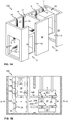
- FIG 1A illustrates schematically a part of an elevator 100 according to an embodiment of the present invention.
- the electric linear motor comprises a stator 15 or stators 15 comprised in a stator beam 14 or beams 14, in this case two.
- a stator beam 14 may be arranged vertically or horizontally, that is, in Fig. 1A , the elevator 100 comprises vertical stator beam 14 or beams 14 and/or horizontal stator beam 14 or beams 14.
- the stator beam 14 or beams 14 may also be arranged to any direction(s) in which the elevator car 10 is desired to be moved.
- One stator beam 14 may, preferably, be comprised of a plurality of stator beam parts arranged one after another to yield the desired length for the stator beam 14 in whole.
- the electric linear motor further comprises a mover 16 or movers 16 arranged or coupled to the elevator car 10 or cars 10.
- the mover 16 or movers 16 are arranged to be in electromagnetic engagement with the stator 15 or stators 15 comprised in the stator beam 14 along which the mover 16 is configured to be moved, thus enabling the movement of the elevator car 10 with which the mover 16 has been mechanically coupled with.
- the stator beams 14 are arranged to the back wall 17 of the elevator shaft 11.
- the elevator shaft 11 refers herein to the elevator car pathway which, as described above, may include vertical parts, horizontal parts, and/or parts having a third direction different with respect to vertical and horizontal directions.
- the part of the elevator shaft 11 depicted in Fig. 1A essentially comprises two vertical parts and one horizontal part.
- the elevator shaft 11 or the elevator car pathway 11 further comprises a front wall 18.
- the front wall 18 may, preferably, comprise an opening 19 for entering into the elevator car 10 or cars 10.
- the opening 19 for entering the elevator cars 10 is arranged only at vertical parts of the elevator shaft 11, the opening 19 may as well be arranged to the horizontal part or any part of the elevator shaft 11.
- the elevator shaft 10 may in some cases comprise only one wall or a structure arranged to accommodate the necessary equipment such as the stator beam 14.
- the elevator shaft 11 or the elevator car pathway 11 does not necessarily have to define a substantially closed volume, that is, surrounded by wall elements or glass or any other structures as long as there is at least a support structure to support the stator beam(s) 14.
- Figure 1A further illustrates that the movers 16 are configured to enable a change in their positions.
- the mover 16 arranged to the elevator car 10 on the left in Fig. 1A is in horizontal position.
- the mover 16 arranged to the elevator car 10 on the right in Fig. 1 is, on the other hand, in vertical position.
- the mover 16 or movers 16 of the elevator 100 are arranged to be rotatable. The movers 16 may thus always be arranged to align with the stator beam 14 along which the mover 16 is arranged to be moved.
- the elevators 100 or particularly the elevator shaft 11 or shafts 11 thereof, according to the various embodiments of the present invention comprise at least one, however, preferably more than one, positions for changing the direction of movement of the elevator car 10, that is, movement direction changing positions 5, at which the direction of movement of an elevator car 10 may be changed from one direction to another, which said another is unparallel relative to said one direction, for example, such as when changing the direction between the vertical and horizontal directions.
- FIG. 1B illustrates schematically the part of the elevator 100 according to the embodiment in Fig. 1A by a sectional view from the back.
- the elevator car 10 on the left corresponds to the elevator car 10 on the right in Fig. 1A , and vice versa.
- the stator beams 14 comprise a plurality of stator beam parts 14A, 14B.
- Some of the stator beam parts, that is, the second parts 14B, of the plurality of stator beam parts are, preferably, arranged in fixed manner in the elevator shaft 11, thus always having same position, preferably, aligned with the direction of the elevator shaft 11 at that particular position.
- stator beam parts that is, the first stator beam parts 14A
- first stator beam parts 14A are rotatable or arranged to be rotated, for example, by an actuator 28, such as an electric motor.
- the elevator 100 comprises at least first stator beam parts 14A, however, in various embodiments also second stator beam parts 14B.
- first stator beam parts 14A At each movement direction changing position 5, there are at least two, preferably at least four, first stator beam parts 14A. These first stator beam parts 14A, for example, a total number of four, are comprised in an arrangement 200 for changing the direction of movement of the elevator car 10. There may, preferably, be one of said arrangement 200 at each one of the movement direction changing positions 5. Said arrangement 200 for changing the direction of movement of the elevator car 10 further comprises an actuator 28 or actuators 28, such as electric motor(s), for rotating one or several of the first stator beam parts 14A comprised in the arrangement 200.
- the actuator 28 may be driven or controlled or operated by a control unit (not shown) or an electrical drive (not shown) coupled to the actuator 28.
- the first stator beam parts 14A are configured to be rotated at least between the vertical and horizontal directions in order to align with the second stator beam parts 14B along which the elevator car 10 is then configured to be further moved.
- the change of the direction of movement of the elevator car 10 may be implemented, for example, so that the elevator car 10 is first moved or driven to the movement direction changing position 5 in such a way that a rotational axis 25 of the first stator beam part 14A aligns with a rotational axis 26 of the corresponding mover 16, as shown in Fig. 1B .
- the first stator beam part 14A begins to rotate, or being rotated by an actuator 28 such as an electric motor driven by an electrical drive, and thus also simultaneously rotates the corresponding rotatable mover 16.
- an actuator 28 such as an electric motor driven by an electrical drive
- the elevator car 10 may be moved in the new direction of the stator beam 14, in this case in the horizontal direction.
- Fig. 1B the elevator car 10 on the left is moving down and approaching a movement direction changing position 5.
- the first stator beam parts 14A of the movement direction changing position 5 in question are arranged already to vertical direction and thus ready to receive the elevator car 10 coming from above.
- the elevator car 10 on the right is, however, already at the other movement direction changing position 5 of Fig. 1B .
- the first stator beam parts 14A are currently still at the horizontal position.
- the first stator beam parts 14A, and thus also the movers 16, of the elevator car 10 may, and have to be, rotated to the vertical direction, such as shown with the two-headed arrows in Fig. 1B , before the elevator car 10 may be further moved upwards.
- the elevator car(s) 10 may, preferably, comprise electrical drive 21 or drives 21 for operating the electrical equipment 23 of the elevator car 10. These may be, for example, lighting, user interfaces, control unit(s), mover(s) of the electric linear motor, emergency brakes, etc.
- the elevator car(s) 10 may also comprise an electrical energy storage 22, such as a battery 22 and, optionally, a capacitor such as a supercapacitor.
- the electrical energy storage 22 may be utilized to provide electrical power to electrical drive 21 or directly to the electrical equipment 23 comprised in the elevator car 10.
- the electrical energy storage 22 may be utilized simultaneously or periodically or depending on the position of the elevator car 10 in the elevator shaft 11 to draw energy from or to store energy into the electrical energy storage 22.
- the mover 16 or movers 16 may be operated or controlled by the electrical drive 21 or drives 21 coupled to the elevator car 10.
- the electrical drive(s) 21 may be, for example, frequency converters or inverters configured to produce alternating current (AC) in order to produce desired current and a magnetic field for generating a force to move the mover 16 along the stator beam 14.
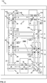
- FIG. 2 illustrates schematically an elevator 100 according to an embodiment of the present invention.
- the elevator 100 comprises a plurality of elevator cars 10, that is, in this case, five.
- the opening(s) 19 for entering the elevator car(s) 10 has been shown with a rectangular having dashed lines representing landing floor doors or door openings 19.
- the movement direction changing positions 5 are arranged at landing floors, however, the movement direction changing positions 5 may as well be arranged at positions other than landing floors, for example, due to a shape of the elevator shaft 11 or elevator car pathway 11 which may have a turn due to the shape and structures of the target, such as a building, into which the elevator 100 has been installed or is to be installed.
- the landing floors may have been arranged at positions other than the movement direction changing positions 5.
- the movement direction changing positions 5 are arranged as pairs having the same position with respect to vertical direction, they may as well be arranged at different positions with respect vertical direction.
- the two columns of landing floors and movement direction changing positions 5 may be identical or may be different.
- FIG 2 further illustrates that each one of the first stator beam parts 14A comprised in one arrangement 200 for changing the direction of movement of the elevator car 10 may be rotated one at a time. This may be especially beneficial when the elevator car 10 is at the movement direction changing position 5.
- By changing the position of each one of the first stator beam parts 14A may cause vibrations or twitches or jerks to the elevator car 10 if the rotational axes 25, 26 are not perfectly aligned.
- the vibrations or jerks of the elevator car 10 may be reduced.
- all of the first stator beam parts 14A of the arrangement at said movement direction changing position 5 may be rotated simultaneously, thus preparing the movement direction changing position 5 more quickly for receiving the next elevator car 10.
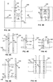
- FIG 3A illustrates schematically an arrangement 200 for changing the direction of movement of an elevator car 10 according to an embodiment of the present invention.
- the arrangement 200 may be arranged to the back wall 17 of the elevator shaft 11 or to any support structure for the stator beam 14 of the electric linear motor of the elevator 100.
- the arrangement comprises a plurality of first stator beam parts 14A, an actuator 28, for example, an electric motor, for changing the position of the first stator beam parts 14A, a control unit 27 for controlling the operation of the actuator 28.
- Figure 3B illustrate an arrangement 200 for changing the direction of movement of an elevator car 10 according to another embodiment of the present invention which is identical to one illustrated in Fig. 3A notwithstanding the way of rotating the first stator beam parts 14A comprised in the arrangement 200.
- the arrangement 200 in Fig. 3B comprises an actuator 28, for example, an electric motor, for changing the changing the position of the first stator beam parts 14A.
- one actuator 28 is responsible for changing the position of each of the first stator beam parts 14A comprised in the arrangement 200.
- This may be implemented by power transmission means for mechanical power transmission 30, such as a belt, band, strap, chain, or the like.
- the first stator beam parts 14A may be configured to be rotatable by utilizing rotation means for producing rotatability 31, such as, a pivot, a bearing, or the like. According to the embodiment in Fig. 3B , all of the first stator beam parts 14A of the arrangement 200 always rotate simultaneously.
- Figure 4A illustrates an arrangement 200 for changing the direction of movement of an elevator car 10 according to an embodiment of the present invention.
- the arrangement 200 may comprise in addition to the first stator beam parts 14A, the control unit 27 (not shown in Figs. 4A-4E for clarity reasons), and the actuator 28 two first auxiliary stator beam parts 14C, for instance.
- first stator beam parts 14A may be identical, however, they do not have to be arranged in identical distances with respect to each other.
- the first stator beam parts 14A In case of four identical first stator beam parts 14A, in order to rotate the parts 14A and to obtain continuous stator beam 14 for moving the elevator car 10, the first stator beam parts 14A must be arranged at certain, same distances from each other.
- first auxiliary stator beam parts 14C provides more freedom for arranging the first stator beam parts 14A of the arrangement 200.
- Figure 4B illustrates an arrangement 200 for changing the direction of movement of an elevator car 10 according to another embodiment of the present invention.
- the first stator beam parts 14A are not identical, but have different lengths. In this case too, however, the distances between the rotational axes are identical; however, they could in this case too be different if first auxiliary stator beam parts 14C would be utilized as in Fig. 4A .
- FIG. 4C illustrates an arrangement 200 for changing the direction of movement of an elevator car 10 according to another embodiment of the present invention.
- the arrangement 200 according to this embodiment comprises two first stator beam parts 14A.
- the stator beam part 14A are essentially identical and in order to form continuous stator beam 14, there are two first auxiliary stator beam parts 14C utilized between a first stator beam part 14A and a second stator beam part 14B as shown in Fig. 4C .
- the first stator beam parts 14A may alternatively be designed so that the first stator beam part 14A on the left is long enough to yield a continuous stator beam 14 without utilizing first auxiliary stator beam parts 14C.
- first stator beam part 14A on the left would be significantly longer than the one on the right, thus resulting in non-identical first stator beam parts 14A, however, by utilizing non-identical first stator beam parts 14A, it is possible to build an arrangement 200 from where the elevator car 10 may continue in all four directions, up, down, left and right. This is not possible in case of utilizing fixedly arranged first auxiliary stator beam parts 14C as shown in Fig. 4C .
- Figure 4D illustrates an arrangement 200 for changing the direction of movement of an elevator car 10 according to still another embodiment of the present invention.
- first auxiliary stator beam parts 14C having vertical and horizontal directions are utilized.
- first auxiliary stator beam parts 14C provides still further freedom to arrange the first stator beam parts 14A appropriately.
- Fig. 4D further illustrates second auxiliary stator beam parts 14D of the arrangement 200.
- These special parts 14D may be adapted to better receive the rotating first stator beam part 14A or they may be utilized as adapters between different second 14B and first stator beam parts 14A.
- second auxiliary stator beam parts 14D it becomes necessary to change only the second auxiliary stator beam parts 14D if the repetitive rotation of the first stator beam part 14A damages the counter-part, avoiding thus the need to change the whole second stator beam part 14B which may be, for example, of the order of some meters or even tens of meters in length.
- Figure 4E illustrates an arrangement 200 for changing the direction of movement of an elevator car 10 according to still another embodiment of the present invention.
- the elevator 100 comprises three parallel stator beams 14 instead of two as shown in Figs. 1A-4D .
- the arrangement 200 thus comprises nine first stator beam parts 14A.
- first auxiliary stator beam parts 14C may be utilized to provide freedom for arranging the first stator beam parts 14A.
- there are three stator beams 14 such as shown in Fig. 4E , however, there are only three first stator beam parts 14A arranged in similar manner as in Fig. 4C . In this case too, it is possible to utilize first auxiliary stator beam parts 14C or to utilize non-identical first stator beam parts 14A.
- the arrangements 200 depicted therein may be utilized for changing the direction of movement of the elevator car 10 in various other directions in addition to ones illustrated (up and left).
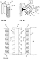
- FIG 5A illustrates schematically a part of the stator beam 14, or a stator beam part 14A, 14B, according to an embodiment of the present invention by a perspective view.
- the part of the stator beam 14 comprises at least one stator 15 extending substantially along the whole stator beam 14.
- the fastening portion 51 may also be a separate fastening portion 51 which may then be attached to the stator beam 14 for arranging the stator beam 14 into the elevator shaft 11 or may be an integrated part of the stator beam 14 or a part thereof.
- the stators 15 may, preferably, be of ferromagnetic material and comprise teeth on their outer surface. According to a preferable embodiment of the present invention, the stator beam 14 or beams 14 are passive in the sense that they do not comprise controllable elements or components, such as coils, for controlling the movement of the mover 16 along the stator beam 14.
- the stator beam 14 or beams 14 may still, however, comprise such active elements as means for rotating a piece or a part of the stator beam 14 or locking means such as for locking the stator beam 14 into a position or, for example, elements utilized for aligning two parts of the stator beam 14 with respect to each other, such as, for example, the dowel 71 or the pin 71 in Fig. 7B .
- FIG. 5B illustrates schematically an electric linear motor, or at least a part thereof, according to an embodiment of the present invention.
- the electric linear motor comprises a mover 16, preferably, a C-shaped or U-shaped (not shown) mover 16.
- the mover 16 comprises at least one unit of electromagnetic components 52 comprising at least one of coil and, optionally, preferably, permanent magnet(s) and/or magnetic core element(s) or ferromagnetic material.
- the unit or units of electromagnetic components 52 may, preferably, be comprised in the mover 16 and adapted to face the stator 15 or stators 15 of the stator beam 14, as shown in Fig. 5B , for instance.
- the units of electromagnetic components 52 are arranged to be in electromagnetic engagement with the stators 15 for moving the mover 16 along the stator beam 14.
- the mover 16 may also be a support portion 53 by which the mover 16 may be attached in rotatable manner to the elevator car 10, for example, to the back wall 17 of the car 10.
- the mover 16 may be shaped and designed in such a way as to enable the movement of the mover 16 along the stator beam 14 without interference from the fastening or support portions 51, 53.
- the movement of the mover 16 along the stator beam 14 may be implemented by known control methods, such as, field-oriented or vector control or the like.
- the basic idea is to produce an alternating magnetic field, for example by an electrical drive 21, by injecting current to a unit of electromagnetic components 52 of the mover 16, such as to a winding or coil thereof.
- the unit of electromagnetic components 52 facing the stator 15 then co-acts with the stator 15 through the electromagnetic engagement and produces a force which moves the mover 16 and thus the elevator car 10 along the stator beam 14.
- FIG. 5C illustrates schematically an electric linear motor, or at least a part thereof, according to an embodiment of the present invention.
- the stator beam 14 comprises stators 15 on opposite sides of the stator beam 14.
- the stators 15 comprise stator teeth having a distance between two consecutive teeth.
- the mover 16 comprises units of electromagnetic components 52 arranged to face the stators 15 of the stator beam 14 and configured to establish an electromagnetic engagement, for example, over an air gap 57 to enable movement of the mover 16 with respect to the stator beam 14, between said units 52 and stators 15.
- the mover 16 comprises mover teeth around which the coils 55A-55C of the units of electromagnetic components 52 may be arranged around.
- each one of said units 52 comprises at least three coils 55A, 55B, 55C, and, optionally, preferably permanent magnets and/or ferromagnetic material 56 or mover irons 56. There may, alternatively, be more or fewer coils.
- the coils 55A-55C may be controlled, for example, so as to inject three-phase current having a phase shift of 120 degrees between two phases.
- the coils 55A-55C may be controlled, as stated hereinbefore, by an electrical drive 21 such as a frequency converter or an inverter. If an electrical energy storage 22, such as a battery, coupled to the elevator car 10 is being utilized, the electrical drive 21 may draw electrical power from the storage 22 to convert the direct current (DC) of the battery to suitable AC for the mover 16 to be moved along the stator beam 14.
- DC direct current
- FIG. 6A illustrates schematically two stator beam parts according to an embodiment of the present invention.
- There may be two first stator beam parts 14A, or one first 14A and one second 14B stator beam part in Fig. 6A .
- At least one end of both of the stator beam parts may have been rounded in order to facilitate to rotating movement of said parts with respect to each other.
- Preferably, only the end or ends of the first stator beam parts 14A may be rounded, however, also other shapes may be utilized in the second stator beam parts 14B for facilitating the movement of the stator beam parts with respect to each other.
- the stator beam parts are aligned and, thus, the mover 16 configured to be moved along the stator beam 14 over the seam between the two stator beam parts.
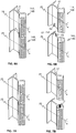
- FIG. 6B illustrates schematically the rotation of the stator beam parts 14A shown in Fig. 6A .
- both of the parts are first stator beam parts 14A and may thus be rotated as shown by the arrows around the axes of rotation 25.
- the stator beam parts 14A may additionally comprise locking or aligning means 61, such as, comprising an alignment part 62, in this case protruding from the stator beam part below, and a counter-part 63, such as the recess 63 or indent 63 in Fig. 6B .
- the stator beam parts are illustrated as being at a distance greater than in Fig. 6A from each other in order to show the locking or aligning means 61 for locking and/or aligning the stator beam parts with respect to each other, that is, for illustrative purposes.
- Figures 7A and 7B illustrate schematically two stator beam parts according to another embodiment of the present invention.
- the distance between the two stator beam parts in Fig. 7B is shown to be greater than in 7A for illustrative purposes.
- the locking or aligning means 61 comprises a dowel 71 or a pin 71 which may be moved or its position changed depending on the position of the stator beam part.
- the dowel 71 may reside inside the stator beam part wherever the stator beam part is being rotated. The dowel 71 may then be pushed out from the stator beam part, for example, by utilizing a mechanism controlled by the control unit 27.
- the mechanism may comprise, for example, electromagnets and/or spring elements, or levers or actuators, such as electric motors or servos.
- the dowel 71 may also be pushed out hydraulically or pneumatically, and then pulled inside the stator beam part by a spring, for instance.
- FIG 8 illustrates schematically an elevator control unit 1000 according to an embodiment of the present invention.
- External units 1001 such as the control units 27 or other equipment of the elevator 100, may be connected to a communication interface 1008 of the elevator control unit 1000.
- External unit 1001 may comprise wireless connection or a connection by a wired manner.
- the communication interface 1008 provides interface for communication with external units 1001 such as the control units 27, elevator car 10, the electric linear motor, or the mover 16 thereof, the doors of the landing floors 19, and/or the electrical drive(s) 21.
- the elevator control unit 1000 may comprise one or more processors 1004, one or more memories 1006 being volatile or non-volatile for storing portions of computer program code 1007A-1007N and any data values and possibly one or more user interface units 1010.
- the mentioned elements may be communicatively coupled to each other with e.g. an internal bus.
- the processor 1004 may be arranged to access the memory 1006 and retrieve and store any information therefrom and thereto.
- the processor 1004 herein refers to any unit suitable for processing information and control the operation of the elevator control unit 1000, among other tasks.
- the operations may also be implemented with a microcontroller solution with embedded software.
- the memory 1006 is not limited to a certain type of memory only, but any memory type suitable for storing the described pieces of information may be applied in the context of the present invention.
- Figure 9 illustrates a flow diagram of a method according to an embodiment of the present invention.
- receiving the movers 16 by the first stator beam parts takes place. This may, preferably, occur by moving the movers 16 by the electric linear motor along the stator beam 14, either along another first 14A or a second 14B stator beam part towards said first stator beam parts 14A.
- aligning the axes of rotation 26 of the movers 16 with the axes of rotation 25 of the first stator beam parts 14A in a first position takes place.
- This may, preferably, also be implemented by controlling the electric linear motor so as to move the movers 16 at positions in which said axes 25, 26 align with respect to each other.
- the "aligning” refers herein to the situation where said axes, which are parallel relative to each other, are at the corresponding positions with respect to each other, that is, for example, as shown in Fig. 1 B for the movers 16 coupled to the elevator car 10 on the right in the figure.
- rotating the first stator beam parts from the first position to a second position by a number of actuators, wherein the movers are being rotated simultaneously along with the rotation of the first stator beam parts takes place.
- the method execution is ended or stopped.
- the method flow may be executed at least once every time the elevator car 10 is at a movement direction changing position 5.
- the method may be executed, for example, twice in case of an override of the control of the movement of an elevator car in case of an emergency.
Landscapes
- Engineering & Computer Science (AREA)
- Automation & Control Theory (AREA)
- Structural Engineering (AREA)
- Civil Engineering (AREA)
- Mechanical Engineering (AREA)
- Types And Forms Of Lifts (AREA)
- Elevator Control (AREA)
- Linear Motors (AREA)
- Lift-Guide Devices, And Elevator Ropes And Cables (AREA)
Priority Applications (6)
| Application Number | Priority Date | Filing Date | Title |
|---|---|---|---|
| ES17174025T ES2882640T3 (es) | 2017-06-01 | 2017-06-01 | Disposición y procedimiento para cambiar la dirección de movimiento de una cabina de un ascensor, y el ascensor correspondiente |
| EP17174025.1A EP3409631B1 (de) | 2017-06-01 | 2017-06-01 | Anordnung und verfahren zur richtungsänderung von bewegungen eines fahrkorbes eines aufzugs, und aufzug dafür |
| PCT/FI2018/050406 WO2018220277A1 (en) | 2017-06-01 | 2018-05-30 | Arrangement and method for changing a direction of movement of an elevator car of an elevator, and the elevator thereof |
| AU2018278302A AU2018278302A1 (en) | 2017-06-01 | 2018-05-30 | Arrangement and method for changing a direction of movement of an elevator car of an elevator, and the elevator thereof |
| CN201880036328.5A CN110691749B (zh) | 2017-06-01 | 2018-05-30 | 用于改变电梯的电梯轿厢的移动方向的装置和方法以及电梯 |
| US16/692,353 US20200087113A1 (en) | 2017-06-01 | 2019-11-22 | Arrangement and method for changing a direction of movement of an elevator car of an elevator, and the elevator thereof |
Applications Claiming Priority (1)
| Application Number | Priority Date | Filing Date | Title |
|---|---|---|---|
| EP17174025.1A EP3409631B1 (de) | 2017-06-01 | 2017-06-01 | Anordnung und verfahren zur richtungsänderung von bewegungen eines fahrkorbes eines aufzugs, und aufzug dafür |
Publications (2)
| Publication Number | Publication Date |
|---|---|
| EP3409631A1 true EP3409631A1 (de) | 2018-12-05 |
| EP3409631B1 EP3409631B1 (de) | 2021-04-28 |
Family
ID=59021346
Family Applications (1)
| Application Number | Title | Priority Date | Filing Date |
|---|---|---|---|
| EP17174025.1A Active EP3409631B1 (de) | 2017-06-01 | 2017-06-01 | Anordnung und verfahren zur richtungsänderung von bewegungen eines fahrkorbes eines aufzugs, und aufzug dafür |
Country Status (6)
| Country | Link |
|---|---|
| US (1) | US20200087113A1 (de) |
| EP (1) | EP3409631B1 (de) |
| CN (1) | CN110691749B (de) |
| AU (1) | AU2018278302A1 (de) |
| ES (1) | ES2882640T3 (de) |
| WO (1) | WO2018220277A1 (de) |
Cited By (7)
| Publication number | Priority date | Publication date | Assignee | Title |
|---|---|---|---|---|
| WO2020216905A1 (de) * | 2019-04-25 | 2020-10-29 | Thyssenkrupp Elevator Innovation And Operations Ag | Aufzugsanlage mit linearantrieb |
| EP3770097A1 (de) * | 2019-07-26 | 2021-01-27 | KONE Corporation | Förderer für personen oder güter mit einem linearmotor |
| BE1027980A1 (de) | 2019-12-19 | 2021-08-04 | Thyssenkrupp Elevator Innovation And Operations Ag | Aufzugsanlage |
| EP3922589A1 (de) * | 2020-06-12 | 2021-12-15 | KONE Corporation | Installationsanordnung und bauzeitaufzug |
| EP3971122A1 (de) | 2020-09-17 | 2022-03-23 | KONE Corporation | Aufzug |
| CN114380164A (zh) * | 2020-10-02 | 2022-04-22 | 通力股份公司 | 用于防止电梯轿厢在电梯系统转向站脱轨的安全装置、电梯系统和方法 |
| EP3988490A1 (de) * | 2020-10-23 | 2022-04-27 | KONE Corporation | Richtungsänderungsanordnung für ein linearmotorfördersystem mit mehrfachmotorkonfiguration, linearmotorsystem und fördersystem |
Families Citing this family (1)
| Publication number | Priority date | Publication date | Assignee | Title |
|---|---|---|---|---|
| WO2018234273A1 (de) * | 2017-06-21 | 2018-12-27 | Thyssenkrupp Elevator Ag | Abstützeinrichtung für eine drehplattform in einer aufzugsanlage |
Citations (3)
| Publication number | Priority date | Publication date | Assignee | Title |
|---|---|---|---|---|
| JPH04191280A (ja) * | 1990-11-27 | 1992-07-09 | Takenaka Komuten Co Ltd | エレベータ駆動装置 |
| WO2016206757A1 (en) * | 2015-06-26 | 2016-12-29 | Kone Corporation | Elevator with linear motor |
| US20170107080A1 (en) * | 2014-03-28 | 2017-04-20 | Thyssenkrupp Elevator Ag | Elevator system |
Family Cites Families (34)
| Publication number | Priority date | Publication date | Assignee | Title |
|---|---|---|---|---|
| US3658155A (en) * | 1970-09-15 | 1972-04-25 | William G Salter | Elevator system |
| GB1393669A (en) * | 1971-07-07 | 1975-05-07 | Trebron Holdings Ltd | Transport systems |
| US4004654A (en) * | 1971-07-07 | 1977-01-25 | Trebron Holdings Limited | Elevator structure supporting apparatus |
| JP2530382B2 (ja) * | 1990-05-14 | 1996-09-04 | 三菱電機株式会社 | リニアモ―タエレベ―タ― |
| JP2529756B2 (ja) * | 1990-06-11 | 1996-09-04 | 三菱電機株式会社 | リニアモ―タエレベ―タ― |
| JPH0717333B2 (ja) * | 1990-08-07 | 1995-03-01 | 鹿島建設株式会社 | リニアモータ駆動エレベータ |
| JPH0585683A (ja) * | 1991-09-25 | 1993-04-06 | Mitsubishi Electric Corp | エレベータ用リニアモータ |
| JPH05186165A (ja) * | 1992-01-16 | 1993-07-27 | Mitsubishi Electric Corp | リニアモータ駆動方式エレベータ装置 |
| ATE192118T1 (de) * | 1997-02-17 | 2000-05-15 | Thyssen Aufzugswerke Gmbh | Linearmotor zum antrieb einer aufzugskabine |
| US20060163008A1 (en) * | 2005-01-24 | 2006-07-27 | Michael Godwin | Autonomous linear retarder/motor for safe operation of direct drive gearless, rope-less elevators |
| NZ552308A (en) * | 2006-02-08 | 2008-11-28 | Inventio Ag | Lift installation with a linear drive system and linear drive system for such a lift installation |
| EP2070860A1 (de) * | 2007-12-11 | 2009-06-17 | Inventio Ag | Aufzugssystem mit vertikal und horizontal verfahrbaren Aufzugkabinen |
| EP2161233B1 (de) * | 2008-09-01 | 2012-02-01 | ThyssenKrupp Elevator AG | Tragvorrichtung zum Umsetzen eines Fahrkorbs eines Aufzugs |
| EP2945897A4 (de) * | 2013-01-17 | 2016-12-14 | Otis Elevator Co | Antriebssystem für aufzüge mit verbesserter entschleunigung |
| EP2994408A4 (de) * | 2013-05-06 | 2017-01-25 | Otis Elevator Company | Linearmotorstatorkern für selbstfahrenden aufzug |
| US20170088396A1 (en) * | 2014-03-14 | 2017-03-30 | Otis Elevator Company | Robust startup method for ropeless elevator |
| DE102014219862A1 (de) * | 2014-09-30 | 2016-03-31 | Thyssenkrupp Ag | Aufzugsystem |
| EP3002243A1 (de) * | 2014-09-30 | 2016-04-06 | Inventio AG | Aufzugssystem mit einzeln angetriebenen Kabinen und geschlossener Fahrbahn |
| DE102014116281A1 (de) * | 2014-11-07 | 2016-05-12 | Thyssenkrupp Ag | Aufzug mit einer Bremsvorrichtung |
| DE102014017486A1 (de) * | 2014-11-27 | 2016-06-02 | Thyssenkrupp Ag | Aufzuganlage mit einer Mehrzahl von Fahrkörben sowie einem dezentralen Sicherheitssystem |
| DE102014017487A1 (de) * | 2014-11-27 | 2016-06-02 | Thyssenkrupp Ag | Verfahren zum Betreiben einer Aufzuganlage sowie zur Ausführung des Verfahrens ausgebildete Aufzugsanlage |
| CN107108166B (zh) * | 2014-12-23 | 2019-05-10 | 奥的斯电梯公司 | 具有线性驱动的电梯系统 |
| CN107108163B (zh) * | 2014-12-30 | 2019-12-03 | 奥的斯电梯公司 | 用于无绳电梯系统的具有子部件和驻停区的冗余的传送站 |
| CN107207204A (zh) * | 2015-01-21 | 2017-09-26 | 奥的斯电梯公司 | 用于多轿厢电梯系统的缓冲装置 |
| KR102534081B1 (ko) * | 2015-01-23 | 2023-05-19 | 오티스 엘리베이터 컴파니 | 엘리베이터 시스템 레일 |
| CN107207196B (zh) * | 2015-02-04 | 2021-01-01 | 奥的斯电梯公司 | 电梯系统评估装置 |
| US10329124B2 (en) * | 2015-08-25 | 2019-06-25 | Otis Elevator Company | Elevator wireless power supply |
| DE102015218025B4 (de) * | 2015-09-18 | 2019-12-12 | Thyssenkrupp Ag | Aufzugsystem |
| US9598265B1 (en) * | 2015-09-28 | 2017-03-21 | Smart Lifts, Llc | Vertically and horizontally mobile elevator cabins |
| WO2018234273A1 (de) * | 2017-06-21 | 2018-12-27 | Thyssenkrupp Elevator Ag | Abstützeinrichtung für eine drehplattform in einer aufzugsanlage |
| EP3667880A1 (de) * | 2018-12-14 | 2020-06-17 | KONE Corporation | Elektrischer linearmotor, aufzug und verfahren zur steuerung der rotation einer bewegungsvorrichtung in bezug auf einen statorträger eines elektrischen linearmotors |
| EP3667879A1 (de) * | 2018-12-14 | 2020-06-17 | KONE Corporation | Elektrischer linearmotor, aufzug und verfahren zur steuerung der rotation einer bewegungsvorrichtung in bezug auf einen statorträger eines elektrischen linearmotors |
| US11469025B2 (en) * | 2019-12-12 | 2022-10-11 | Honeywell Federal Manufacturing & Technologies, Llc | Electromagnetic propulsion system |
| EP3995424A1 (de) * | 2020-11-04 | 2022-05-11 | KONE Corporation | Bremssystem für eine aufzugskabine und aufzugsanlage |
-
2017
- 2017-06-01 ES ES17174025T patent/ES2882640T3/es active Active
- 2017-06-01 EP EP17174025.1A patent/EP3409631B1/de active Active
-
2018
- 2018-05-30 WO PCT/FI2018/050406 patent/WO2018220277A1/en not_active Ceased
- 2018-05-30 AU AU2018278302A patent/AU2018278302A1/en not_active Abandoned
- 2018-05-30 CN CN201880036328.5A patent/CN110691749B/zh active Active
-
2019
- 2019-11-22 US US16/692,353 patent/US20200087113A1/en not_active Abandoned
Patent Citations (3)
| Publication number | Priority date | Publication date | Assignee | Title |
|---|---|---|---|---|
| JPH04191280A (ja) * | 1990-11-27 | 1992-07-09 | Takenaka Komuten Co Ltd | エレベータ駆動装置 |
| US20170107080A1 (en) * | 2014-03-28 | 2017-04-20 | Thyssenkrupp Elevator Ag | Elevator system |
| WO2016206757A1 (en) * | 2015-06-26 | 2016-12-29 | Kone Corporation | Elevator with linear motor |
Cited By (11)
| Publication number | Priority date | Publication date | Assignee | Title |
|---|---|---|---|---|
| WO2020216905A1 (de) * | 2019-04-25 | 2020-10-29 | Thyssenkrupp Elevator Innovation And Operations Ag | Aufzugsanlage mit linearantrieb |
| CN113727932A (zh) * | 2019-04-25 | 2021-11-30 | 蒂森克虏伯电梯创新与运营有限公司 | 具有线性驱动装置的电梯设备 |
| EP3770097A1 (de) * | 2019-07-26 | 2021-01-27 | KONE Corporation | Förderer für personen oder güter mit einem linearmotor |
| CN112299208A (zh) * | 2019-07-26 | 2021-02-02 | 通力股份公司 | 用于乘客或货物的输送机 |
| CN112299208B (zh) * | 2019-07-26 | 2025-05-16 | 通力股份公司 | 用于乘客或货物的输送机 |
| BE1027980A1 (de) | 2019-12-19 | 2021-08-04 | Thyssenkrupp Elevator Innovation And Operations Ag | Aufzugsanlage |
| BE1027980B1 (de) * | 2019-12-19 | 2021-08-10 | Thyssenkrupp Elevator Innovation And Operations Ag | Aufzugsanlage |
| EP3922589A1 (de) * | 2020-06-12 | 2021-12-15 | KONE Corporation | Installationsanordnung und bauzeitaufzug |
| EP3971122A1 (de) | 2020-09-17 | 2022-03-23 | KONE Corporation | Aufzug |
| CN114380164A (zh) * | 2020-10-02 | 2022-04-22 | 通力股份公司 | 用于防止电梯轿厢在电梯系统转向站脱轨的安全装置、电梯系统和方法 |
| EP3988490A1 (de) * | 2020-10-23 | 2022-04-27 | KONE Corporation | Richtungsänderungsanordnung für ein linearmotorfördersystem mit mehrfachmotorkonfiguration, linearmotorsystem und fördersystem |
Also Published As
| Publication number | Publication date |
|---|---|
| EP3409631B1 (de) | 2021-04-28 |
| US20200087113A1 (en) | 2020-03-19 |
| CN110691749B (zh) | 2021-07-20 |
| AU2018278302A1 (en) | 2019-12-12 |
| ES2882640T3 (es) | 2021-12-02 |
| CN110691749A (zh) | 2020-01-14 |
| WO2018220277A1 (en) | 2018-12-06 |
Similar Documents
| Publication | Publication Date | Title |
|---|---|---|
| EP3409631B1 (de) | Anordnung und verfahren zur richtungsänderung von bewegungen eines fahrkorbes eines aufzugs, und aufzug dafür | |
| US10574166B2 (en) | Electric linear motor for an elevator and method for controlling thereof | |
| US20200109031A1 (en) | Movable maintenance robot system, method for providing maintenance to an elevator car of an elevator and elevator | |
| CN108946404B (zh) | 用于电梯轿厢的无线功率传送装置以及电梯 | |
| US11012019B2 (en) | Electric linear motor, elevator and method for controlling rotation of a mover with respect to a stator beam of an electric linear motor | |
| US11025186B2 (en) | Electric linear motor, elevator and method for controlling rotation of a mover with respect to a stator beam of an electric linear motor | |
| EP3517474A1 (de) | Verfahren und aufzugssteuerung zur steuerung eines türstufenspaltes eines aufzugs und einen aufzug | |
| CN108880179A (zh) | 具有开关磁通直线电机的门操作器 | |
| EP3569549A1 (de) | Frei schwebende führungsschuhanordnung, verfahren zur führung einer aufzugskabine entlang eines statorträgers eines elektrischen linearmotors während einer notsituation sowie aufzug mit verwendung der frei schwebenden führungsschuhanordnung davon | |
| US20200361747A1 (en) | Inclined elevator and method for manufacturing thereof | |
| US20210078832A1 (en) | Device, elevator, and method for moving an elevator car of an elevator | |
| HK40019961A (en) | Arrangement and method for changing a direction of movement of an elevator car of an elevator, and the elevator thereof | |
| HK40019961B (en) | Arrangement and method for changing a direction of movement of an elevator car of an elevator, and the elevator thereof | |
| CN107482873B (zh) | 一种低磁阻力永磁直线电机 | |
| US12497264B2 (en) | Method for operating an elevator and elevator | |
| EP3666715A1 (de) | Elektrischer linearmotor und aufzug | |
| WO2021052564A1 (en) | Linear rotor for an electric linear motor, electric linear motor and elevator | |
| US20220135373A1 (en) | Brake system for an elevator car and elevator system | |
| EP3418242A1 (de) | Bewegungselement eines elektrischen linearmotors für einen aufzug und aufzug | |
| HK40032775A (en) | Electric linear motor and elevator | |
| EP3560872A1 (de) | Verfahren zur elektrischen leistungsübertragung in einem aufzug und aufzug | |
| HK40032098A (en) | Electric linear motor and elevator | |
| HK40000844A (en) | Wireless power transfer arrangement for an elevator car and an elevator | |
| HK40033654A (en) | Inclined elevator and method for manufacturing thereof | |
| CN110112887A (zh) | 一种用于机器人一体化关节结构的球形电机 |
Legal Events
| Date | Code | Title | Description |
|---|---|---|---|
| PUAI | Public reference made under article 153(3) epc to a published international application that has entered the european phase |
Free format text: ORIGINAL CODE: 0009012 |
|
| STAA | Information on the status of an ep patent application or granted ep patent |
Free format text: STATUS: THE APPLICATION HAS BEEN PUBLISHED |
|
| AK | Designated contracting states |
Kind code of ref document: A1 Designated state(s): AL AT BE BG CH CY CZ DE DK EE ES FI FR GB GR HR HU IE IS IT LI LT LU LV MC MK MT NL NO PL PT RO RS SE SI SK SM TR |
|
| AX | Request for extension of the european patent |
Extension state: BA ME |
|
| STAA | Information on the status of an ep patent application or granted ep patent |
Free format text: STATUS: REQUEST FOR EXAMINATION WAS MADE |
|
| 17P | Request for examination filed |
Effective date: 20190605 |
|
| RBV | Designated contracting states (corrected) |
Designated state(s): AL AT BE BG CH CY CZ DE DK EE ES FI FR GB GR HR HU IE IS IT LI LT LU LV MC MK MT NL NO PL PT RO RS SE SI SK SM TR |
|
| GRAP | Despatch of communication of intention to grant a patent |
Free format text: ORIGINAL CODE: EPIDOSNIGR1 |
|
| STAA | Information on the status of an ep patent application or granted ep patent |
Free format text: STATUS: GRANT OF PATENT IS INTENDED |
|
| INTG | Intention to grant announced |
Effective date: 20200619 |
|
| GRAJ | Information related to disapproval of communication of intention to grant by the applicant or resumption of examination proceedings by the epo deleted |
Free format text: ORIGINAL CODE: EPIDOSDIGR1 |
|
| STAA | Information on the status of an ep patent application or granted ep patent |
Free format text: STATUS: REQUEST FOR EXAMINATION WAS MADE |
|
| GRAS | Grant fee paid |
Free format text: ORIGINAL CODE: EPIDOSNIGR3 |
|
| STAA | Information on the status of an ep patent application or granted ep patent |
Free format text: STATUS: GRANT OF PATENT IS INTENDED |
|
| INTC | Intention to grant announced (deleted) | ||
| GRAP | Despatch of communication of intention to grant a patent |
Free format text: ORIGINAL CODE: EPIDOSNIGR1 |
|
| INTG | Intention to grant announced |
Effective date: 20201125 |
|
| GRAA | (expected) grant |
Free format text: ORIGINAL CODE: 0009210 |
|
| STAA | Information on the status of an ep patent application or granted ep patent |
Free format text: STATUS: THE PATENT HAS BEEN GRANTED |
|
| AK | Designated contracting states |
Kind code of ref document: B1 Designated state(s): AL AT BE BG CH CY CZ DE DK EE ES FI FR GB GR HR HU IE IS IT LI LT LU LV MC MK MT NL NO PL PT RO RS SE SI SK SM TR |
|
| REG | Reference to a national code |
Ref country code: GB Ref legal event code: FG4D |
|
| REG | Reference to a national code |
Ref country code: CH Ref legal event code: EP |
|
| REG | Reference to a national code |
Ref country code: AT Ref legal event code: REF Ref document number: 1386860 Country of ref document: AT Kind code of ref document: T Effective date: 20210515 |
|
| REG | Reference to a national code |
Ref country code: DE Ref legal event code: R096 Ref document number: 602017037451 Country of ref document: DE |
|
| REG | Reference to a national code |
Ref country code: IE Ref legal event code: FG4D |
|
| REG | Reference to a national code |
Ref country code: LT Ref legal event code: MG9D |
|
| REG | Reference to a national code |
Ref country code: AT Ref legal event code: MK05 Ref document number: 1386860 Country of ref document: AT Kind code of ref document: T Effective date: 20210428 |
|
| PG25 | Lapsed in a contracting state [announced via postgrant information from national office to epo] |
Ref country code: LT Free format text: LAPSE BECAUSE OF FAILURE TO SUBMIT A TRANSLATION OF THE DESCRIPTION OR TO PAY THE FEE WITHIN THE PRESCRIBED TIME-LIMIT Effective date: 20210428 Ref country code: FI Free format text: LAPSE BECAUSE OF FAILURE TO SUBMIT A TRANSLATION OF THE DESCRIPTION OR TO PAY THE FEE WITHIN THE PRESCRIBED TIME-LIMIT Effective date: 20210428 Ref country code: HR Free format text: LAPSE BECAUSE OF FAILURE TO SUBMIT A TRANSLATION OF THE DESCRIPTION OR TO PAY THE FEE WITHIN THE PRESCRIBED TIME-LIMIT Effective date: 20210428 Ref country code: BG Free format text: LAPSE BECAUSE OF FAILURE TO SUBMIT A TRANSLATION OF THE DESCRIPTION OR TO PAY THE FEE WITHIN THE PRESCRIBED TIME-LIMIT Effective date: 20210728 Ref country code: AT Free format text: LAPSE BECAUSE OF FAILURE TO SUBMIT A TRANSLATION OF THE DESCRIPTION OR TO PAY THE FEE WITHIN THE PRESCRIBED TIME-LIMIT Effective date: 20210428 Ref country code: NL Free format text: LAPSE BECAUSE OF FAILURE TO SUBMIT A TRANSLATION OF THE DESCRIPTION OR TO PAY THE FEE WITHIN THE PRESCRIBED TIME-LIMIT Effective date: 20210428 |
|
| PG25 | Lapsed in a contracting state [announced via postgrant information from national office to epo] |
Ref country code: IS Free format text: LAPSE BECAUSE OF FAILURE TO SUBMIT A TRANSLATION OF THE DESCRIPTION OR TO PAY THE FEE WITHIN THE PRESCRIBED TIME-LIMIT Effective date: 20210828 Ref country code: LV Free format text: LAPSE BECAUSE OF FAILURE TO SUBMIT A TRANSLATION OF THE DESCRIPTION OR TO PAY THE FEE WITHIN THE PRESCRIBED TIME-LIMIT Effective date: 20210428 Ref country code: GR Free format text: LAPSE BECAUSE OF FAILURE TO SUBMIT A TRANSLATION OF THE DESCRIPTION OR TO PAY THE FEE WITHIN THE PRESCRIBED TIME-LIMIT Effective date: 20210729 Ref country code: PL Free format text: LAPSE BECAUSE OF FAILURE TO SUBMIT A TRANSLATION OF THE DESCRIPTION OR TO PAY THE FEE WITHIN THE PRESCRIBED TIME-LIMIT Effective date: 20210428 Ref country code: NO Free format text: LAPSE BECAUSE OF FAILURE TO SUBMIT A TRANSLATION OF THE DESCRIPTION OR TO PAY THE FEE WITHIN THE PRESCRIBED TIME-LIMIT Effective date: 20210728 Ref country code: PT Free format text: LAPSE BECAUSE OF FAILURE TO SUBMIT A TRANSLATION OF THE DESCRIPTION OR TO PAY THE FEE WITHIN THE PRESCRIBED TIME-LIMIT Effective date: 20210830 Ref country code: RS Free format text: LAPSE BECAUSE OF FAILURE TO SUBMIT A TRANSLATION OF THE DESCRIPTION OR TO PAY THE FEE WITHIN THE PRESCRIBED TIME-LIMIT Effective date: 20210428 Ref country code: SE Free format text: LAPSE BECAUSE OF FAILURE TO SUBMIT A TRANSLATION OF THE DESCRIPTION OR TO PAY THE FEE WITHIN THE PRESCRIBED TIME-LIMIT Effective date: 20210428 |
|
| PGFP | Annual fee paid to national office [announced via postgrant information from national office to epo] |
Ref country code: ES Payment date: 20210827 Year of fee payment: 5 |
|
| REG | Reference to a national code |
Ref country code: ES Ref legal event code: FG2A Ref document number: 2882640 Country of ref document: ES Kind code of ref document: T3 Effective date: 20211202 |
|
| REG | Reference to a national code |
Ref country code: NL Ref legal event code: MP Effective date: 20210428 |
|
| PG25 | Lapsed in a contracting state [announced via postgrant information from national office to epo] |
Ref country code: SK Free format text: LAPSE BECAUSE OF FAILURE TO SUBMIT A TRANSLATION OF THE DESCRIPTION OR TO PAY THE FEE WITHIN THE PRESCRIBED TIME-LIMIT Effective date: 20210428 Ref country code: SM Free format text: LAPSE BECAUSE OF FAILURE TO SUBMIT A TRANSLATION OF THE DESCRIPTION OR TO PAY THE FEE WITHIN THE PRESCRIBED TIME-LIMIT Effective date: 20210428 Ref country code: RO Free format text: LAPSE BECAUSE OF FAILURE TO SUBMIT A TRANSLATION OF THE DESCRIPTION OR TO PAY THE FEE WITHIN THE PRESCRIBED TIME-LIMIT Effective date: 20210428 Ref country code: EE Free format text: LAPSE BECAUSE OF FAILURE TO SUBMIT A TRANSLATION OF THE DESCRIPTION OR TO PAY THE FEE WITHIN THE PRESCRIBED TIME-LIMIT Effective date: 20210428 Ref country code: DK Free format text: LAPSE BECAUSE OF FAILURE TO SUBMIT A TRANSLATION OF THE DESCRIPTION OR TO PAY THE FEE WITHIN THE PRESCRIBED TIME-LIMIT Effective date: 20210428 Ref country code: CZ Free format text: LAPSE BECAUSE OF FAILURE TO SUBMIT A TRANSLATION OF THE DESCRIPTION OR TO PAY THE FEE WITHIN THE PRESCRIBED TIME-LIMIT Effective date: 20210428 Ref country code: MC Free format text: LAPSE BECAUSE OF FAILURE TO SUBMIT A TRANSLATION OF THE DESCRIPTION OR TO PAY THE FEE WITHIN THE PRESCRIBED TIME-LIMIT Effective date: 20210428 |
|
| REG | Reference to a national code |
Ref country code: DE Ref legal event code: R097 Ref document number: 602017037451 Country of ref document: DE Ref country code: CH Ref legal event code: PL |
|
| PLBE | No opposition filed within time limit |
Free format text: ORIGINAL CODE: 0009261 |
|
| STAA | Information on the status of an ep patent application or granted ep patent |
Free format text: STATUS: NO OPPOSITION FILED WITHIN TIME LIMIT |
|
| REG | Reference to a national code |
Ref country code: BE Ref legal event code: MM Effective date: 20210630 |
|
| PG25 | Lapsed in a contracting state [announced via postgrant information from national office to epo] |
Ref country code: LU Free format text: LAPSE BECAUSE OF NON-PAYMENT OF DUE FEES Effective date: 20210601 |
|
| 26N | No opposition filed |
Effective date: 20220131 |
|
| PG25 | Lapsed in a contracting state [announced via postgrant information from national office to epo] |
Ref country code: LI Free format text: LAPSE BECAUSE OF NON-PAYMENT OF DUE FEES Effective date: 20210630 Ref country code: IE Free format text: LAPSE BECAUSE OF NON-PAYMENT OF DUE FEES Effective date: 20210601 Ref country code: CH Free format text: LAPSE BECAUSE OF NON-PAYMENT OF DUE FEES Effective date: 20210630 |
|
| PG25 | Lapsed in a contracting state [announced via postgrant information from national office to epo] |
Ref country code: IS Free format text: LAPSE BECAUSE OF FAILURE TO SUBMIT A TRANSLATION OF THE DESCRIPTION OR TO PAY THE FEE WITHIN THE PRESCRIBED TIME-LIMIT Effective date: 20210828 Ref country code: AL Free format text: LAPSE BECAUSE OF FAILURE TO SUBMIT A TRANSLATION OF THE DESCRIPTION OR TO PAY THE FEE WITHIN THE PRESCRIBED TIME-LIMIT Effective date: 20210428 |
|
| PG25 | Lapsed in a contracting state [announced via postgrant information from national office to epo] |
Ref country code: IT Free format text: LAPSE BECAUSE OF FAILURE TO SUBMIT A TRANSLATION OF THE DESCRIPTION OR TO PAY THE FEE WITHIN THE PRESCRIBED TIME-LIMIT Effective date: 20210428 Ref country code: BE Free format text: LAPSE BECAUSE OF NON-PAYMENT OF DUE FEES Effective date: 20210630 |
|
| PG25 | Lapsed in a contracting state [announced via postgrant information from national office to epo] |
Ref country code: CY Free format text: LAPSE BECAUSE OF FAILURE TO SUBMIT A TRANSLATION OF THE DESCRIPTION OR TO PAY THE FEE WITHIN THE PRESCRIBED TIME-LIMIT Effective date: 20210428 |
|
| P01 | Opt-out of the competence of the unified patent court (upc) registered |
Effective date: 20230525 |
|
| REG | Reference to a national code |
Ref country code: ES Ref legal event code: FD2A Effective date: 20230726 |
|
| PG25 | Lapsed in a contracting state [announced via postgrant information from national office to epo] |
Ref country code: HU Free format text: LAPSE BECAUSE OF FAILURE TO SUBMIT A TRANSLATION OF THE DESCRIPTION OR TO PAY THE FEE WITHIN THE PRESCRIBED TIME-LIMIT; INVALID AB INITIO Effective date: 20170601 |
|
| PG25 | Lapsed in a contracting state [announced via postgrant information from national office to epo] |
Ref country code: ES Free format text: LAPSE BECAUSE OF NON-PAYMENT OF DUE FEES Effective date: 20220602 |
|
| PG25 | Lapsed in a contracting state [announced via postgrant information from national office to epo] |
Ref country code: MK Free format text: LAPSE BECAUSE OF FAILURE TO SUBMIT A TRANSLATION OF THE DESCRIPTION OR TO PAY THE FEE WITHIN THE PRESCRIBED TIME-LIMIT Effective date: 20210428 |
|
| PG25 | Lapsed in a contracting state [announced via postgrant information from national office to epo] |
Ref country code: MT Free format text: LAPSE BECAUSE OF FAILURE TO SUBMIT A TRANSLATION OF THE DESCRIPTION OR TO PAY THE FEE WITHIN THE PRESCRIBED TIME-LIMIT Effective date: 20210428 |
|
| PGFP | Annual fee paid to national office [announced via postgrant information from national office to epo] |
Ref country code: DE Payment date: 20250618 Year of fee payment: 9 |
|
| PGFP | Annual fee paid to national office [announced via postgrant information from national office to epo] |
Ref country code: GB Payment date: 20250618 Year of fee payment: 9 |
|
| PGFP | Annual fee paid to national office [announced via postgrant information from national office to epo] |
Ref country code: FR Payment date: 20250625 Year of fee payment: 9 |
|
| PG25 | Lapsed in a contracting state [announced via postgrant information from national office to epo] |
Ref country code: TR Free format text: LAPSE BECAUSE OF FAILURE TO SUBMIT A TRANSLATION OF THE DESCRIPTION OR TO PAY THE FEE WITHIN THE PRESCRIBED TIME-LIMIT Effective date: 20210428 |