EP3409634B1 - Amortisseur d'oscillations d'un joint rotatif suspendu - Google Patents
Amortisseur d'oscillations d'un joint rotatif suspendu Download PDFInfo
- Publication number
- EP3409634B1 EP3409634B1 EP18166027.5A EP18166027A EP3409634B1 EP 3409634 B1 EP3409634 B1 EP 3409634B1 EP 18166027 A EP18166027 A EP 18166027A EP 3409634 B1 EP3409634 B1 EP 3409634B1
- Authority
- EP
- European Patent Office
- Prior art keywords
- friction
- pressure
- disc
- joint pin
- socket
- Prior art date
- Legal status (The legal status is an assumption and is not a legal conclusion. Google has not performed a legal analysis and makes no representation as to the accuracy of the status listed.)
- Active
Links
Images


Classifications
-
- B—PERFORMING OPERATIONS; TRANSPORTING
- B66—HOISTING; LIFTING; HAULING
- B66C—CRANES; LOAD-ENGAGING ELEMENTS OR DEVICES FOR CRANES, CAPSTANS, WINCHES, OR TACKLES
- B66C3/00—Load-engaging elements or devices attached to lifting or lowering gear of cranes or adapted for connection therewith and intended primarily for transmitting lifting forces to loose materials; Grabs
- B66C3/005—Grab supports, e.g. articulations; Oscillation dampers; Orientation
-
- E—FIXED CONSTRUCTIONS
- E02—HYDRAULIC ENGINEERING; FOUNDATIONS; SOIL SHIFTING
- E02F—DREDGING; SOIL-SHIFTING
- E02F9/00—Component parts of dredgers or soil-shifting machines, not restricted to one of the kinds covered by groups E02F3/00 - E02F7/00
- E02F9/006—Pivot joint assemblies
-
- F—MECHANICAL ENGINEERING; LIGHTING; HEATING; WEAPONS; BLASTING
- F16—ENGINEERING ELEMENTS AND UNITS; GENERAL MEASURES FOR PRODUCING AND MAINTAINING EFFECTIVE FUNCTIONING OF MACHINES OR INSTALLATIONS; THERMAL INSULATION IN GENERAL
- F16F—SPRINGS; SHOCK-ABSORBERS; MEANS FOR DAMPING VIBRATION
- F16F7/00—Vibration-dampers; Shock-absorbers
- F16F7/02—Vibration-dampers; Shock-absorbers with relatively-rotatable friction surfaces that are pressed together
- F16F7/04—Vibration-dampers; Shock-absorbers with relatively-rotatable friction surfaces that are pressed together in the direction of the axis of rotation
-
- E—FIXED CONSTRUCTIONS
- E02—HYDRAULIC ENGINEERING; FOUNDATIONS; SOIL SHIFTING
- E02F—DREDGING; SOIL-SHIFTING
- E02F3/00—Dredgers; Soil-shifting machines
- E02F3/04—Dredgers; Soil-shifting machines mechanically-driven
- E02F3/28—Dredgers; Soil-shifting machines mechanically-driven with digging tools mounted on a dipper- or bucket-arm, i.e. there is either one arm or a pair of arms, e.g. dippers, buckets
- E02F3/36—Component parts
- E02F3/3604—Devices to connect tools to arms, booms or the like
- E02F3/3677—Devices to connect tools to arms, booms or the like allowing movement, e.g. rotation or translation, of the tool around or along another axis as the movement implied by the boom or arms, e.g. for tilting buckets
- E02F3/3681—Rotators
Definitions
- Present invention relates to a swing damper for a hanging rotary joint. More specifically the invention relates to the swing damper to be used in a rotary joint between a jib and a working tool (for example a gripping unit (gripper) and a hanger) in order to avoid and dampen swinging of the gripper or the hanger at the end of the jib.
- a working tool for example a gripping unit (gripper) and a hanger
- said device is also called an oscillation or swinging brake and formerly the device was also called a scissor-damper.
- the swing damper according to the present invention is also called a friction type damper, i.e. in its structure friction elements and friction discs are used, due to the mutual friction of which unwanted swinging movement is supressed.
- the present invention relates to a swing damper of a rotary hanging joint, the first goal of which is to damp the swinging movement between working device attached to the end of a jib and the jib itself.
- the present invention relates to the swing damper of the hanging rotary joint, in which the swing damper is attached on the end of the rotary joint outside of the rotary joint and comprises two pressure discs coaxial with a joint pin, wherein the rotational movement of the pressure discs around the longitudinal axis of the joint pin is fixed in respect of one pivoting half of the rotary joint.
- the rotary joint comprises a friction disc between the pressure discs, the rotary movement of which around the joint pin is fixed in respect to the other pivoting half of the rotary joint.
- the friction disc comprises at least one friction element made of the friction material.
- At the end of the joint pin there is a pressure device for pressing the pressure discs against the friction element(s) of the friction disc.
- pivoting halves of a joint in the present context means the parts of the structure which in relation to each other are pivoting around the joint pin of the rotary joint.
- This other half has a working device attached to it, such as a gripping unit or a similar device, or another crosswise rotary joint (in respect to the previous rotary joint), to which the working device is attached.
- the friction disc comprises at least one through socket, in which there is a friction element of friction material, having two parallel and opposite planar contact surfaces, which are pressed by the pressure device into contact with the first and the second friction disc respectively.
- the friction disc comprises several through sockets symmetrical in respect to the central bore in the disc, all of them comprising a friction element of the friction material and having the shape corresponding to the shape of the socket.
- the advantage of the several friction elements is a larger total friction surface, and also the fact, that in case of damage or a breakdown of one of the friction elements the structure as a whole does not automatically become disabled - the dampening effect may be reduced, but the device as a whole continues to operate with other intact friction elements.
- the friction element is pressed into its respective socket preferably by interference fit.
- the friction element may be fixed into the socket by glue joint. Positioning of the friction element into its socket using interference fit or glue joint substantially facilitates the assembly of the swing damper and it is especially beneficial when replacing the friction disc in the field.
- the structure according to the present invention is capable of working with the friction elements that are placed into the sockets with clearance fit, i.e. with so-called floating elements.
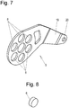
- the friction disc comprises several circular sockets symmetrical in relation to the central bore in the friction disc, in each socket there is friction element of the friction material, having the shape corresponding to the shape of the perimeter of the socket.
- the friction disc comprises several sockets symmetrical in relation to the central bore in the friction disc, said sockets having the shape of a ring sector, in each socket there is a friction element of the friction material, having the shape corresponding to the shape of the perimeter of the socket.
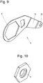
- the friction disc comprises a single socket of a polygonal shape symmetrical to the centre of the friction disc, where the socket contains a single friction element of the friction material, having the shape corresponding to the shape of the perimeter of the socket and comprising in the centre a through opening for a joint pin.
- the pressure device comprises on the joint pin a conical disc spring package comprising at least one conical disc spring, by which pressure is generated from the end of the joint pin to squeeze the friction disc between the two pressure discs.
- the conical disc spring pack of the pressure device comprises three conical disc springs.
- a spiral compression spring instead of a conical disc springs may be used.
- an elastic element of the elastic material instead of the conical disc springs or the spiral compression spring an elastic element of the elastic material may be used.
- the pressure device comprises a pressure nut at the end of the joint pin, which allows to adjust pressure of the pressure discs exerted by the conical disc spring pack or the spiral compression spring against the friction disc.
- This pressure nut is also used to restore the pressure of the pressure disc against the friction disc exerted by the conical disc spring pack or the spiral compression spring when the friction elements start to wear (i.e. by screwing on pressure).
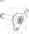
- a swing damper 1 comprises at the end of a joint pin 2 of a rotary joint two pressure discs 3, 4 that are coaxial with the longitudinal axis of joint pin 2.
- Both pressure discs 3 and 4 have projecting levers (15 and 16) in order to fix the rotational movement of the respective pressure discs 3, 4 around the longitudinal axis of the rotary joint in relation to the respective half of the rotary joint.
- joint pin 2 Coaxially with joint pin 2 between pressure discs 3, 4 there is a friction disc 5, the rotational motion of which around the longitudinal axis of joint pin 2 is fixed in relation to the other half of the rotary joint.
- Friction disc 5 comprises at least one socket 8 through friction disc 5, in which there is a friction element 6 having two parallel flat contact surfaces on opposite sides of friction element 6, that by means of a pressure device 7 are on both sides of friction disc 5 pressed into contact with the first and second pressure disc 3 and 4, respectively.
- Friction elements 6 are preferably pressed into sockets 8 with interference fit or fixed by glued joint. This avoids movement of the friction element 6 relative to the socket.
- joint pin 2 there is mounted friction disc 5 with friction elements 6 lying in its sockets 8. Thereafter the so-called outer second pressure disc 4 is pushed onto joint pin 2.
- joint pin 2 pressure device 7 is mounted, comprising a package of conical disc springs, which in the present embodiments includes three conical disc springs 9.
- disc springs 9 also a spiral compression spring may be used.
- shoulder 11 upon exerting pressure on pressure discs 3 and 4 by pressure device 7 against friction elements 6 of friction disc 5, the force formed to generate the pressure is not transferred in the longitudinal direction of the joint pin to other elements of the rotary joint.
- pressure discs 3 and 4 are fixed with retainer bolt 13 to one moving half of the rotary joint so, that the rotational movement of pressure discs 3 and 4 around the longitudinal axis of joint pin 2 takes place together with said half of the rotary joint.
- outer pressure disc 4 is at that fixed by the head 14 of retainer bolt 13.
- Pressure discs 3 and 4 have respective levers 15 and 16 and are fixed using respective bores 17 and 18 for retainer bolt 13 and its head 14.
- Friction disc 5 is fixed by means of lever 19 protruding from it and a bore 20 at the end of lever 19 relative to the other moving half of the rotary joint such that the rotational movement of friction disc 5 around the longitudinal axis of joint pin 2 takes place together with the other moving half of the rotary joint.
- friction elements 6 are mounted in the sockets of friction disc 5, then rotation of friction disc 5 between the friction elements and pressure discs 3 and 4 relative to pressure discs 3 and 4 is impeded due to friction, i.e. for pivoting friction disc 5 in relative to pressure discs 3 and 4 a friction force between them has to be exceeded.
- pivoting of friction disc 5 relative to pressure discs 3 and 4 is suppressed and together with them also the swinging movement around the rotary joint.
- friction elements 6 are not glued to friction disc 5, the problems associated with the glued joint, such as detachment of glued joint, are entirely avoided. Also it is sufficient during maintenance works to replace only worn friction elements 6 in sockets 8 and instead of replacing friction disc 5.
- pressure disc 4 can just be pulled away from the end of joint pin 2 and simply the worn friction elements 6 in sockets 8 of friction disc can be replaced when necessary.
- Pressure nut 10 at the end of joint pin 2 enables easy adjustment of the pressure generated by pressure discs 3 and 4 against friction elements 6 of friction disc 5 if required.
- friction disc 5 comprises sockets 8 and friction elements 6 in the shape of a sector of the circle in order to maximize the contact surface between planar friction elements 6 and pressure discs 3 and 4.
- friction disc 5 comprises circular sockets 8 and friction elements 6, which are easiest to manufacture.
- friction disc 5 comprises a single socket 8 for a friction element 6 to be inserted thereto as shown in Figure 10 .
- a perimeter of the socket has the shape of a hexagon.
- the perimeter of friction disc 6 has also the shape of a hexagon and consequently friction element 6 inserted into socket 8 cannot rotate.
Landscapes
- Engineering & Computer Science (AREA)
- General Engineering & Computer Science (AREA)
- Mechanical Engineering (AREA)
- Mining & Mineral Resources (AREA)
- Civil Engineering (AREA)
- Structural Engineering (AREA)
- Vibration Dampers (AREA)
- Pivots And Pivotal Connections (AREA)
Claims (12)
- Amortisseur (1) d'oscillations d'un joint rotatif suspendu, l'amortisseur (1) d' oscillations étant situé à l'extrémité d'un axe d'articulation (2) du joint rotatif et comprenant deux disques de pression (3, 4) coaxiaux à l'axe d'articulation (2), où le mouvement de rotation des disques de pression autour de l'axe longitudinal de l'axe d'articulation (2) est fixé par rapport à une moitié pivotante du joint rotatif, et entre les disques de pression (3, 4), il y a un disque de friction (5) coaxial avec l'axe d'articulation (2), où le mouvement de rotation du disque de friction (5) autour de l'axe longitudinal de l'articulation (2) est fixé par rapport à l'autre moitié pivotante de l'articulation rotative, le disque de friction (5) comprenant au moins un élément de friction (6) du matériau de friction, à l'extrémité de l'axe d'articulation (2), est un dispositif de pression (7) servant à presser les disques de pression (3, 4) contre l'élément de friction (6) du disque de friction (5), caractérisé en ce que le disque de friction (5) comprend au moins une douille (8) traversant le disque de friction (5), dans laquelle est monté l'élément de friction (6) du matériau de friction, comportant deux surfaces de contact planes sur les côtés opposés de l'élément de friction (6), qui sont pressés sur les côtés opposés du disque de friction (5) en contact respectivement avec les disques de pression intérieur et extérieur (3, 4) au moyen du dispositif de pression (7).
- Amortisseur pour un enjeu selon la revendication 1, caractérisé en ce que le disque de friction (5) comprend plusieurs douilles (8) placées symétriquement par rapport à l'alésage central dans le disque de friction (5), chaque douille (8) comprenant ledit élément de friction (6) du matériau de friction, ayant une forme correspondant à la forme du périmètre de la douille (8).
- Amortisseur pour un enjeu selon la revendication 1, caractérisé en ce que le disque de friction (5) comprend plusieurs douilles circulaires (8) placées symétriquement par rapport à l'alésage central dans le disque de friction (5), chaque douille (8) comprenant ledit élément de friction (6) du matériau de friction, ayant une forme correspondant à la forme du périmètre de la douille (8).
- Amortisseur pour un enjeu selon la revendication 1, caractérisé en ce que le disque de friction (5) comprend plusieurs douilles (8) en forme de secteur d'anneau et placées symétriquement par rapport à l'alésage central du disque de friction (5), chaque douille (8) comprenant ledit élément de friction (6) du matériau de friction, ayant une forme correspondant à la forme du périmètre de la douille (8).
- Amortisseur pour un enjeu selon la revendication 1, caractérisé en ce que le disque de friction (5) comprend une seule douille (8) de forme polygonale symétrique qui est située symétriquement par rapport au centre du disque de friction et dans la douille un seul élément de friction (6) du matériau de friction, ayant une forme correspondant à la forme du périmètre de la douille et comprenant une ouverture traversante au centre pour l'axe d'articulation (2).
- Amortisseur pour un enjeu selon l'une quelconque des revendications précédentes, caractérisé en ce que le dispositif de pression (7) comprend sur l'axe d'articulation (2) un boîtier de ressort à disque conique comprenant au moins un ressort à disque conique (9) par lequel une pression est générée à partir de l'extrémité de l'axe d'articulation (2) pour presser le disque de friction (5) entre les deux disques de pression (3, 4).
- Amortisseur pour un enjeu selon la revendication 6, caractérisé en ce que le boîtier de ressort à disque conique du dispositif de pression (7) comprend trois ressorts à disque conique (9).
- Amortisseur pour un enjeu selon l'une des revendications précédentes 6 ou 7, caractérisé en ce que le dispositif de pression (7) comporte à l'extrémité de l'axe d'articulation (2) un écrou de pression (10) au moyen duquel la pression des disques de pression (3, 4) généré par le boîtier de ressort à disque conique contre au moins un élément de friction (6) du disque de friction (5) peut être ajusté.
- Amortisseur pour un enjeu selon l'une quelconque des revendications précédentes 1 à 5, caractérisé en ce que le dispositif de pression (7) comprend sur l'axe d'articulation (2) un ressort en spirale par lequel une pression est générée à partir de l'extrémité de l'axe d'articulation (2) pour presser le disque de friction (5) entre les deux disques de pression (3, 4).
- Amortisseur pour un enjeu selon la revendication 9, caractérisé en ce que le dispositif de pression (7) comprend à l'extrémité de l'axe d'articulation (2) un écrou de pression (10) à l'aide duquel la pression des disques de pression (3, 4) générée par le ressort en spirale contre au moins un élément de friction (6) du disque de friction (5) peut être ajusté.
- Amortisseur pour un enjeu selon l'une quelconque des revendications précédentes, caractérisé en ce que les éléments de friction (6) ont été montés dans les douilles (8) par ajustement avec serrage.
- Amortisseur pour un enjeu selon l'une quelconque des revendications précédentes, caractérisé en ce que les éléments de friction (6) ont été fixés dans les douilles (8) par un joint collé.
Priority Applications (2)
| Application Number | Priority Date | Filing Date | Title |
|---|---|---|---|
| SI201830006T SI3409634T1 (sl) | 2017-05-29 | 2018-04-06 | Nihalni dušilnik visečega zgiba |
| PL18166027T PL3409634T3 (pl) | 2017-05-29 | 2018-04-06 | Tłumik kołysania wiszącego przegubu obrotowego |
Applications Claiming Priority (1)
| Application Number | Priority Date | Filing Date | Title |
|---|---|---|---|
| EEU201700027U EE01456U1 (et) | 2017-05-29 | 2017-05-29 | Riputuspöördliigendi kiikesummuti |
Publications (3)
| Publication Number | Publication Date |
|---|---|
| EP3409634A1 EP3409634A1 (fr) | 2018-12-05 |
| EP3409634A8 EP3409634A8 (fr) | 2019-02-20 |
| EP3409634B1 true EP3409634B1 (fr) | 2019-07-03 |
Family
ID=61911463
Family Applications (1)
| Application Number | Title | Priority Date | Filing Date |
|---|---|---|---|
| EP18166027.5A Active EP3409634B1 (fr) | 2017-05-29 | 2018-04-06 | Amortisseur d'oscillations d'un joint rotatif suspendu |
Country Status (4)
| Country | Link |
|---|---|
| EP (1) | EP3409634B1 (fr) |
| EE (1) | EE01456U1 (fr) |
| PL (1) | PL3409634T3 (fr) |
| SI (1) | SI3409634T1 (fr) |
Families Citing this family (2)
| Publication number | Priority date | Publication date | Assignee | Title |
|---|---|---|---|---|
| CN116923715B (zh) * | 2022-04-06 | 2026-04-14 | 海鹰航空通用装备有限责任公司 | 一种拦阻钩对中装置 |
| AT527926B1 (de) | 2024-05-14 | 2025-08-15 | Lechner Konrad | Pendelgelenk zur befestigung hydraulisch betätigter arbeitsgeräte |
Family Cites Families (3)
| Publication number | Priority date | Publication date | Assignee | Title |
|---|---|---|---|---|
| US5110169A (en) | 1990-10-03 | 1992-05-05 | Deere & Company | Grease loaded grapple dampener |
| SE523382C2 (sv) * | 1999-03-09 | 2004-04-13 | Indexator Ab | Anordning och förfarande vid en svängdämpare samt användning av sådan |
| SE525863C2 (sv) | 2002-10-07 | 2005-05-17 | Indexator Ab | Arrangemang vid en svängdämpare till t ex kran och ett förfarande vid en sådan |
-
2017
- 2017-05-29 EE EEU201700027U patent/EE01456U1/et active Protection Beyond IP Right Term
-
2018
- 2018-04-06 EP EP18166027.5A patent/EP3409634B1/fr active Active
- 2018-04-06 SI SI201830006T patent/SI3409634T1/sl unknown
- 2018-04-06 PL PL18166027T patent/PL3409634T3/pl unknown
Also Published As
| Publication number | Publication date |
|---|---|
| EE01456U1 (et) | 2019-02-15 |
| EP3409634A8 (fr) | 2019-02-20 |
| EP3409634A1 (fr) | 2018-12-05 |
| SI3409634T1 (sl) | 2019-11-29 |
| PL3409634T3 (pl) | 2020-06-01 |
Similar Documents
| Publication | Publication Date | Title |
|---|---|---|
| US7721857B2 (en) | Arrangement related to a swing damper | |
| CN103233991A (zh) | 盘式制动器和盘式制动器的调节装置 | |
| EP3409634B1 (fr) | Amortisseur d'oscillations d'un joint rotatif suspendu | |
| CN101165281B (zh) | 用于销式抓斗器具的间距组件和使用该间距组件的器具组件 | |
| CN102943495B (zh) | 铰链机构 | |
| US9114681B2 (en) | Suspension assembly for an automotive vehicle and automotive vehicle comprising such a suspension assembly | |
| US9067764B2 (en) | Swing damper with disc brakes | |
| US20190293108A1 (en) | A screw-retaining device and screw-retaining kit | |
| CA2015689C (fr) | Goupille d'assemblage pre-chargee, pivotante, de frein a disque | |
| US20140027222A1 (en) | Swing damper with disc brakes and its control mechanism | |
| CN104500522B (zh) | 双螺母锁紧机构 | |
| CN114833561A (zh) | 用于螺纹连接件的紧固装置与安全装置的布置结构 | |
| CN202468776U (zh) | 机械驱动式双领蹄鼓式制动器 | |
| CA2520778C (fr) | Rotor d'helicoptere | |
| US5730430A (en) | Spring unit for use in a pivot pin assembly | |
| CN203611673U (zh) | 一种钢板弹簧固定机构 | |
| CN219792309U (zh) | 一种卷扬机抱式离合机构 | |
| EP2704976B1 (fr) | Amortisseur doté de freins à disque et son mécanisme de commande | |
| WO2024229992A1 (fr) | Mécanisme d'embrayage de treuil de type à maintien | |
| US9982731B2 (en) | Disc brake apparatus | |
| EP3463768B1 (fr) | Dispositif d'équilibrage à ressort et robot industriel comprenant un dispositif d'équilibrage à ressort | |
| USH2012H1 (en) | Braked joint assembly | |
| US20220025924A1 (en) | Joint element provided with swing dampener brake, joint assembly comprising the joint element, and machine comprising the joint assembly | |
| EP3019430B1 (fr) | Anneau de levage | |
| CN220283417U (zh) | 一种支腿装置及工程机械 |
Legal Events
| Date | Code | Title | Description |
|---|---|---|---|
| PUAI | Public reference made under article 153(3) epc to a published international application that has entered the european phase |
Free format text: ORIGINAL CODE: 0009012 |
|
| STAA | Information on the status of an ep patent application or granted ep patent |
Free format text: STATUS: THE APPLICATION HAS BEEN PUBLISHED |
|
| AK | Designated contracting states |
Kind code of ref document: A1 Designated state(s): AL AT BE BG CH CY CZ DE DK EE ES FI FR GB GR HR HU IE IS IT LI LT LU LV MC MK MT NL NO PL PT RO RS SE SI SK SM TR |
|
| AX | Request for extension of the european patent |
Extension state: BA ME |
|
| RAP1 | Party data changed (applicant data changed or rights of an application transferred) |
Owner name: OUE PALMSE MEHAANIKAKODA |
|
| STAA | Information on the status of an ep patent application or granted ep patent |
Free format text: STATUS: REQUEST FOR EXAMINATION WAS MADE |
|
| 17P | Request for examination filed |
Effective date: 20190218 |
|
| RBV | Designated contracting states (corrected) |
Designated state(s): AL AT BE BG CH CY CZ DE DK EE ES FI FR GB GR HR HU IE IS IT LI LT LU LV MC MK MT NL NO PL PT RO RS SE SI SK SM TR |
|
| GRAP | Despatch of communication of intention to grant a patent |
Free format text: ORIGINAL CODE: EPIDOSNIGR1 |
|
| STAA | Information on the status of an ep patent application or granted ep patent |
Free format text: STATUS: GRANT OF PATENT IS INTENDED |
|
| RIC1 | Information provided on ipc code assigned before grant |
Ipc: E02F 3/36 20060101ALI20190403BHEP Ipc: E02F 9/00 20060101ALI20190403BHEP Ipc: F16F 7/04 20060101ALI20190403BHEP Ipc: B66C 3/00 20060101AFI20190403BHEP |
|
| INTG | Intention to grant announced |
Effective date: 20190424 |
|
| GRAS | Grant fee paid |
Free format text: ORIGINAL CODE: EPIDOSNIGR3 |
|
| GRAA | (expected) grant |
Free format text: ORIGINAL CODE: 0009210 |
|
| STAA | Information on the status of an ep patent application or granted ep patent |
Free format text: STATUS: THE PATENT HAS BEEN GRANTED |
|
| AK | Designated contracting states |
Kind code of ref document: B1 Designated state(s): AL AT BE BG CH CY CZ DE DK EE ES FI FR GB GR HR HU IE IS IT LI LT LU LV MC MK MT NL NO PL PT RO RS SE SI SK SM TR |
|
| REG | Reference to a national code |
Ref country code: GB Ref legal event code: FG4D |
|
| REG | Reference to a national code |
Ref country code: CH Ref legal event code: EP Ref country code: AT Ref legal event code: REF Ref document number: 1150762 Country of ref document: AT Kind code of ref document: T Effective date: 20190715 |
|
| REG | Reference to a national code |
Ref country code: IE Ref legal event code: FG4D |
|
| REG | Reference to a national code |
Ref country code: DE Ref legal event code: R096 Ref document number: 602018000206 Country of ref document: DE |
|
| REG | Reference to a national code |
Ref country code: NL Ref legal event code: MP Effective date: 20190703 |
|
| REG | Reference to a national code |
Ref country code: LT Ref legal event code: MG4D |
|
| PG25 | Lapsed in a contracting state [announced via postgrant information from national office to epo] |
Ref country code: PT Free format text: LAPSE BECAUSE OF FAILURE TO SUBMIT A TRANSLATION OF THE DESCRIPTION OR TO PAY THE FEE WITHIN THE PRESCRIBED TIME-LIMIT Effective date: 20191104 Ref country code: NO Free format text: LAPSE BECAUSE OF FAILURE TO SUBMIT A TRANSLATION OF THE DESCRIPTION OR TO PAY THE FEE WITHIN THE PRESCRIBED TIME-LIMIT Effective date: 20191003 Ref country code: BG Free format text: LAPSE BECAUSE OF FAILURE TO SUBMIT A TRANSLATION OF THE DESCRIPTION OR TO PAY THE FEE WITHIN THE PRESCRIBED TIME-LIMIT Effective date: 20191003 Ref country code: SE Free format text: LAPSE BECAUSE OF FAILURE TO SUBMIT A TRANSLATION OF THE DESCRIPTION OR TO PAY THE FEE WITHIN THE PRESCRIBED TIME-LIMIT Effective date: 20190703 Ref country code: CZ Free format text: LAPSE BECAUSE OF FAILURE TO SUBMIT A TRANSLATION OF THE DESCRIPTION OR TO PAY THE FEE WITHIN THE PRESCRIBED TIME-LIMIT Effective date: 20190703 Ref country code: NL Free format text: LAPSE BECAUSE OF FAILURE TO SUBMIT A TRANSLATION OF THE DESCRIPTION OR TO PAY THE FEE WITHIN THE PRESCRIBED TIME-LIMIT Effective date: 20190703 Ref country code: HR Free format text: LAPSE BECAUSE OF FAILURE TO SUBMIT A TRANSLATION OF THE DESCRIPTION OR TO PAY THE FEE WITHIN THE PRESCRIBED TIME-LIMIT Effective date: 20190703 Ref country code: LT Free format text: LAPSE BECAUSE OF FAILURE TO SUBMIT A TRANSLATION OF THE DESCRIPTION OR TO PAY THE FEE WITHIN THE PRESCRIBED TIME-LIMIT Effective date: 20190703 |
|
| PG25 | Lapsed in a contracting state [announced via postgrant information from national office to epo] |
Ref country code: IS Free format text: LAPSE BECAUSE OF FAILURE TO SUBMIT A TRANSLATION OF THE DESCRIPTION OR TO PAY THE FEE WITHIN THE PRESCRIBED TIME-LIMIT Effective date: 20191103 Ref country code: LV Free format text: LAPSE BECAUSE OF FAILURE TO SUBMIT A TRANSLATION OF THE DESCRIPTION OR TO PAY THE FEE WITHIN THE PRESCRIBED TIME-LIMIT Effective date: 20190703 Ref country code: RS Free format text: LAPSE BECAUSE OF FAILURE TO SUBMIT A TRANSLATION OF THE DESCRIPTION OR TO PAY THE FEE WITHIN THE PRESCRIBED TIME-LIMIT Effective date: 20190703 Ref country code: GR Free format text: LAPSE BECAUSE OF FAILURE TO SUBMIT A TRANSLATION OF THE DESCRIPTION OR TO PAY THE FEE WITHIN THE PRESCRIBED TIME-LIMIT Effective date: 20191004 Ref country code: ES Free format text: LAPSE BECAUSE OF FAILURE TO SUBMIT A TRANSLATION OF THE DESCRIPTION OR TO PAY THE FEE WITHIN THE PRESCRIBED TIME-LIMIT Effective date: 20190703 Ref country code: AL Free format text: LAPSE BECAUSE OF FAILURE TO SUBMIT A TRANSLATION OF THE DESCRIPTION OR TO PAY THE FEE WITHIN THE PRESCRIBED TIME-LIMIT Effective date: 20190703 |
|
| PG25 | Lapsed in a contracting state [announced via postgrant information from national office to epo] |
Ref country code: TR Free format text: LAPSE BECAUSE OF FAILURE TO SUBMIT A TRANSLATION OF THE DESCRIPTION OR TO PAY THE FEE WITHIN THE PRESCRIBED TIME-LIMIT Effective date: 20190703 |
|
| PG25 | Lapsed in a contracting state [announced via postgrant information from national office to epo] |
Ref country code: EE Free format text: LAPSE BECAUSE OF FAILURE TO SUBMIT A TRANSLATION OF THE DESCRIPTION OR TO PAY THE FEE WITHIN THE PRESCRIBED TIME-LIMIT Effective date: 20190703 Ref country code: DK Free format text: LAPSE BECAUSE OF FAILURE TO SUBMIT A TRANSLATION OF THE DESCRIPTION OR TO PAY THE FEE WITHIN THE PRESCRIBED TIME-LIMIT Effective date: 20190703 Ref country code: IT Free format text: LAPSE BECAUSE OF FAILURE TO SUBMIT A TRANSLATION OF THE DESCRIPTION OR TO PAY THE FEE WITHIN THE PRESCRIBED TIME-LIMIT Effective date: 20190703 Ref country code: RO Free format text: LAPSE BECAUSE OF FAILURE TO SUBMIT A TRANSLATION OF THE DESCRIPTION OR TO PAY THE FEE WITHIN THE PRESCRIBED TIME-LIMIT Effective date: 20190703 |
|
| PG25 | Lapsed in a contracting state [announced via postgrant information from national office to epo] |
Ref country code: IS Free format text: LAPSE BECAUSE OF FAILURE TO SUBMIT A TRANSLATION OF THE DESCRIPTION OR TO PAY THE FEE WITHIN THE PRESCRIBED TIME-LIMIT Effective date: 20200224 Ref country code: SM Free format text: LAPSE BECAUSE OF FAILURE TO SUBMIT A TRANSLATION OF THE DESCRIPTION OR TO PAY THE FEE WITHIN THE PRESCRIBED TIME-LIMIT Effective date: 20190703 Ref country code: SK Free format text: LAPSE BECAUSE OF FAILURE TO SUBMIT A TRANSLATION OF THE DESCRIPTION OR TO PAY THE FEE WITHIN THE PRESCRIBED TIME-LIMIT Effective date: 20190703 |
|
| REG | Reference to a national code |
Ref country code: DE Ref legal event code: R097 Ref document number: 602018000206 Country of ref document: DE |
|
| PLBE | No opposition filed within time limit |
Free format text: ORIGINAL CODE: 0009261 |
|
| STAA | Information on the status of an ep patent application or granted ep patent |
Free format text: STATUS: NO OPPOSITION FILED WITHIN TIME LIMIT |
|
| PG2D | Information on lapse in contracting state deleted |
Ref country code: IS |
|
| 26N | No opposition filed |
Effective date: 20200603 |
|
| PG25 | Lapsed in a contracting state [announced via postgrant information from national office to epo] |
Ref country code: MC Free format text: LAPSE BECAUSE OF FAILURE TO SUBMIT A TRANSLATION OF THE DESCRIPTION OR TO PAY THE FEE WITHIN THE PRESCRIBED TIME-LIMIT Effective date: 20190703 |
|
| PG25 | Lapsed in a contracting state [announced via postgrant information from national office to epo] |
Ref country code: LU Free format text: LAPSE BECAUSE OF NON-PAYMENT OF DUE FEES Effective date: 20200406 |
|
| REG | Reference to a national code |
Ref country code: BE Ref legal event code: MM Effective date: 20200430 |
|
| PG25 | Lapsed in a contracting state [announced via postgrant information from national office to epo] |
Ref country code: BE Free format text: LAPSE BECAUSE OF NON-PAYMENT OF DUE FEES Effective date: 20200430 |
|
| PG25 | Lapsed in a contracting state [announced via postgrant information from national office to epo] |
Ref country code: IE Free format text: LAPSE BECAUSE OF NON-PAYMENT OF DUE FEES Effective date: 20200406 |
|
| PG25 | Lapsed in a contracting state [announced via postgrant information from national office to epo] |
Ref country code: LI Free format text: LAPSE BECAUSE OF NON-PAYMENT OF DUE FEES Effective date: 20210430 Ref country code: CH Free format text: LAPSE BECAUSE OF NON-PAYMENT OF DUE FEES Effective date: 20210430 |
|
| REG | Reference to a national code |
Ref country code: AT Ref legal event code: UEP Ref document number: 1150762 Country of ref document: AT Kind code of ref document: T Effective date: 20190703 |
|
| PG25 | Lapsed in a contracting state [announced via postgrant information from national office to epo] |
Ref country code: MT Free format text: LAPSE BECAUSE OF FAILURE TO SUBMIT A TRANSLATION OF THE DESCRIPTION OR TO PAY THE FEE WITHIN THE PRESCRIBED TIME-LIMIT Effective date: 20190703 Ref country code: CY Free format text: LAPSE BECAUSE OF FAILURE TO SUBMIT A TRANSLATION OF THE DESCRIPTION OR TO PAY THE FEE WITHIN THE PRESCRIBED TIME-LIMIT Effective date: 20190703 |
|
| PG25 | Lapsed in a contracting state [announced via postgrant information from national office to epo] |
Ref country code: MK Free format text: LAPSE BECAUSE OF FAILURE TO SUBMIT A TRANSLATION OF THE DESCRIPTION OR TO PAY THE FEE WITHIN THE PRESCRIBED TIME-LIMIT Effective date: 20190703 |
|
| GBPC | Gb: european patent ceased through non-payment of renewal fee |
Effective date: 20220406 |
|
| PG25 | Lapsed in a contracting state [announced via postgrant information from national office to epo] |
Ref country code: GB Free format text: LAPSE BECAUSE OF NON-PAYMENT OF DUE FEES Effective date: 20220406 |
|
| P01 | Opt-out of the competence of the unified patent court (upc) registered |
Effective date: 20230530 |
|
| PGFP | Annual fee paid to national office [announced via postgrant information from national office to epo] |
Ref country code: SI Payment date: 20250317 Year of fee payment: 8 |
|
| PGFP | Annual fee paid to national office [announced via postgrant information from national office to epo] |
Ref country code: PL Payment date: 20250218 Year of fee payment: 8 |
|
| PGFP | Annual fee paid to national office [announced via postgrant information from national office to epo] |
Ref country code: DE Payment date: 20250428 Year of fee payment: 8 |
|
| PGFP | Annual fee paid to national office [announced via postgrant information from national office to epo] |
Ref country code: FR Payment date: 20250424 Year of fee payment: 8 |
|
| PGFP | Annual fee paid to national office [announced via postgrant information from national office to epo] |
Ref country code: AT Payment date: 20250417 Year of fee payment: 8 |
|
| PGFP | Annual fee paid to national office [announced via postgrant information from national office to epo] |
Ref country code: FI Payment date: 20260326 Year of fee payment: 9 |