EP3409848B1 - Dispositif de reconnaissance d"accessoire - Google Patents
Dispositif de reconnaissance d"accessoire Download PDFInfo
- Publication number
- EP3409848B1 EP3409848B1 EP17759605.3A EP17759605A EP3409848B1 EP 3409848 B1 EP3409848 B1 EP 3409848B1 EP 17759605 A EP17759605 A EP 17759605A EP 3409848 B1 EP3409848 B1 EP 3409848B1
- Authority
- EP
- European Patent Office
- Prior art keywords
- attachment
- posture
- feature amount
- unit
- recognition
- Prior art date
- Legal status (The legal status is an assumption and is not a legal conclusion. Google has not performed a legal analysis and makes no representation as to the accuracy of the status listed.)
- Not-in-force
Links
Images





Classifications
-
- E—FIXED CONSTRUCTIONS
- E02—HYDRAULIC ENGINEERING; FOUNDATIONS; SOIL SHIFTING
- E02F—DREDGING; SOIL-SHIFTING
- E02F3/00—Dredgers; Soil-shifting machines
- E02F3/04—Dredgers; Soil-shifting machines mechanically-driven
- E02F3/96—Dredgers; Soil-shifting machines mechanically-driven with arrangements for alternate or simultaneous use of different digging elements
- E02F3/963—Arrangements on backhoes for alternate use of different tools
-
- E—FIXED CONSTRUCTIONS
- E02—HYDRAULIC ENGINEERING; FOUNDATIONS; SOIL SHIFTING
- E02F—DREDGING; SOIL-SHIFTING
- E02F9/00—Component parts of dredgers or soil-shifting machines, not restricted to one of the kinds covered by groups E02F3/00 - E02F7/00
- E02F9/26—Indicating devices
- E02F9/264—Sensors and their calibration for indicating the position of the work tool
- E02F9/265—Sensors and their calibration for indicating the position of the work tool with follow-up actions (e.g. control signals sent to actuate the work tool)
-
- E—FIXED CONSTRUCTIONS
- E02—HYDRAULIC ENGINEERING; FOUNDATIONS; SOIL SHIFTING
- E02F—DREDGING; SOIL-SHIFTING
- E02F3/00—Dredgers; Soil-shifting machines
- E02F3/04—Dredgers; Soil-shifting machines mechanically-driven
- E02F3/28—Dredgers; Soil-shifting machines mechanically-driven with digging tools mounted on a dipper- or bucket-arm, i.e. there is either one arm or a pair of arms, e.g. dippers, buckets
- E02F3/36—Component parts
-
- E—FIXED CONSTRUCTIONS
- E02—HYDRAULIC ENGINEERING; FOUNDATIONS; SOIL SHIFTING
- E02F—DREDGING; SOIL-SHIFTING
- E02F3/00—Dredgers; Soil-shifting machines
- E02F3/04—Dredgers; Soil-shifting machines mechanically-driven
- E02F3/96—Dredgers; Soil-shifting machines mechanically-driven with arrangements for alternate or simultaneous use of different digging elements
-
- E—FIXED CONSTRUCTIONS
- E02—HYDRAULIC ENGINEERING; FOUNDATIONS; SOIL SHIFTING
- E02F—DREDGING; SOIL-SHIFTING
- E02F9/00—Component parts of dredgers or soil-shifting machines, not restricted to one of the kinds covered by groups E02F3/00 - E02F7/00
- E02F9/24—Safety devices, e.g. for preventing overload
-
- E—FIXED CONSTRUCTIONS
- E02—HYDRAULIC ENGINEERING; FOUNDATIONS; SOIL SHIFTING
- E02F—DREDGING; SOIL-SHIFTING
- E02F9/00—Component parts of dredgers or soil-shifting machines, not restricted to one of the kinds covered by groups E02F3/00 - E02F7/00
- E02F9/26—Indicating devices
- E02F9/264—Sensors and their calibration for indicating the position of the work tool
-
- G—PHYSICS
- G06—COMPUTING OR CALCULATING; COUNTING
- G06T—IMAGE DATA PROCESSING OR GENERATION, IN GENERAL
- G06T7/00—Image analysis
-
- G—PHYSICS
- G06—COMPUTING OR CALCULATING; COUNTING
- G06T—IMAGE DATA PROCESSING OR GENERATION, IN GENERAL
- G06T7/00—Image analysis
- G06T7/0002—Inspection of images, e.g. flaw detection
- G06T7/0004—Industrial image inspection
- G06T7/001—Industrial image inspection using an image reference approach
-
- G—PHYSICS
- G06—COMPUTING OR CALCULATING; COUNTING
- G06T—IMAGE DATA PROCESSING OR GENERATION, IN GENERAL
- G06T7/00—Image analysis
- G06T7/70—Determining position or orientation of objects or cameras
- G06T7/73—Determining position or orientation of objects or cameras using feature-based methods
-
- G—PHYSICS
- G06—COMPUTING OR CALCULATING; COUNTING
- G06T—IMAGE DATA PROCESSING OR GENERATION, IN GENERAL
- G06T2207/00—Indexing scheme for image analysis or image enhancement
- G06T2207/30—Subject of image; Context of image processing
- G06T2207/30108—Industrial image inspection
- G06T2207/30164—Workpiece; Machine component
Definitions
- the present invention relates to an attachment recognition device for recognizing an attachment installed in an attachment installation unit in a construction machine equipped with a work device including the attachment installation unit in which a plurality of types of attachment is installed in a replaceable manner.
- a user performs work by appropriately changing an attachment such as a bucket, a nibbler, and a breaker according to the work. If the construction machine fails to recognize information such as a size of the attachment, interference prevention control for preventing interference of the attachment in a cab and operation control of a work device according to the attachment (for example, automatic horizontal pulling control of a bucket) may not function effectively. Therefore, the construction machine needs to recognize the currently installed attachment.
- Patent Literatures 1 and 2 are known.
- Patent Literature 1 discloses a technique in which, when a service person replaces an attachment, the service person inputs identification information about the attachment and transmits the identification information together with the input date and time to a terminal device, and then the terminal device manages the attachment installed in a construction machine.
- Patent Literature 2 discloses a technique to obtain a difference in measurement data of a predetermined part between a standard attachment and a replacement attachment when the standard attachment serving as an attachment before replacement and the replacement attachment are set in a predetermined measurement posture, and to calculate numerical data about a size and shape of the replacement attachment based on the obtained difference and previously stored numerical data about the size and shape of the standard attachment.
- a posture of a bucket is set in a posture in which a tip is brought into contact with the ground to cause an upper surface to agree with a vertical direction before and after bucket replacement, angles of a boom and an arm are measured, and the measured angles are substituted into a predetermined arithmetic expression to obtain an attachment length.
- Patent Literature 1 is based on manual input of the identification information by the service person, causing a problem that human error such as input error and forgotten input occurs.
- Patent Literature 2 has a problem that measurement takes time because both attachments of the standard attachment and the replacement attachment are set in the measurement posture by an operator's operation. Also, Patent Literature 2 has a problem that, since it is necessary to measure the standard attachment serving as an attachment before replacement, if measurement work is neglected at the time of replacement of the attachment, the replacement attachment cannot be recognized. Further prior art documents are: Patent Literature 3 which discloses an interference preventive device for a working machine and forms the basis for the preamble of the independent claim.
- An attachment recognition device for recognizing an attachment installed in an attachment installation unit in a construction machine including a work device including the attachment installation unit in which a plurality of types of attachment is installed in a replaceable manner.
- the attachment recognition device includes: a posture detection unit configured to detect a posture of the work device; a distance sensor configured to acquire distance image data of a surrounding object including the installed attachment; a region extraction unit configured to extract a region indicating distance distribution of the installed attachment from the distance image data acquired by the distance sensor by using the posture detected by the posture detection unit; a feature amount extraction unit configured to extract a feature amount of the installed attachment from the region extracted by the region extraction unit; a database configured to store a feature amount of one or more types of reference attachment in advance; and an attachment recognition unit configured to make comparison of the feature amount extracted by the feature amount extraction unit and the feature amount of the reference attachment to recognize the installed attachment.
- the attachment can be recognized even if no identification information about the attachment is manually input.
- measurement work can be completed in a short time.
- FIG. 1 is an external view of a construction machine 1 to which an attachment recognition device according to embodiments of the present invention is applied.
- a hybrid excavator is described as the construction machine 1 as an example, but the attachment recognition device may be applied to other construction machines such as a hydraulic excavator and a crane.
- a front side direction of a cab 31 is described as a front direction
- a rear side direction of the cab 31 is described as a rear direction
- an upper side direction of the cab 31 is described as an upper direction
- a lower side direction of the cab 31 is described as a lower direction.
- the front and rear directions are collectively described as a front-rear direction
- the upper and lower directions are collectively described as an upper-lower direction.
- a left side direction is described as a left direction
- a right side direction is described as a right direction.
- the right and left directions are collectively described as a right-left direction.
- the construction machine 1 includes a crawler type lower traveling body 2, an upper slewing body 3 (one example of a main body) provided on the lower traveling body 2 in a rotatable manner, and a posture-changeable work device 4 attached to the upper slewing body 3.
- the work device 4 includes a boom 15 (one example of a movable part) attached to the upper slewing body 3, for example, adjacently to the right direction of the cab 31 such that the boom 15 can be raised and lowered, an arm 16 (one example of a movable part) pivotably attached to a tip portion of the boom 15, and an attachment 17 pivotably installed in an attachment installation unit r provided at a tip of the arm 16.
- the attachment 17 is installed in the attachment installation unit r in a replaceable manner.
- a bucket, a nibbler, a breaker, and the like can be employed.
- the upper slewing body 3 is composed of a box body, and includes the cab 31 an operator boards. In the cab 31, a front side surface is described as a front surface 31a.
- a distance sensor 110 is provided at a predetermined position (here, an upper end) of the front surface 31a.
- a measurement range D100 is set so as to cover at least an entire region of the front surface 31a.
- an angle of view of the measurement range D100 is set at approximately 90 degrees, but this is one example.
- an interference object such as a tip of the attachment 17 and an obstacle grasped by the attachment 17 enters a predetermined distance range from the front surface 31a, this will allow the construction machine 1 to issue a warning to the operator or to perform interference prevention control to control the work device 4 so as to prevent interference of the interference object on the front surface 31a.
- the construction machine 1 further includes angle sensors 101, 102, and 103.
- the angle sensor 101 is provided at a rotational fulcrum of the boom 15 and measures a rotation angle of the boom 15.
- the angle sensor 102 is provided at a rotational fulcrum of the arm 16 and measures a rotation angle of the arm 16.
- the angle sensor 103 is provided at a rotational fulcrum of the attachment 17 and measures a rotation angle of the attachment 17.
- the upper slewing body 3 is provided with a controller 120 that is electrically connected to the distance sensor 110 and controls the entire construction machine 1.
- a memory 130M is electrically connected to the controller 120.
- the memory 130M is configured of a nonvolatile storage device, and stores a database 130 illustrated in FIG. 2 .
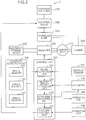
- FIG. 2 is a block diagram illustrating one example of a system configuration of the construction machine 1 illustrated in FIG. 1 .
- the construction machine 1 includes an engine 210, a hydraulic pump 250 and a generator-motor 220 coupled with an output shaft of the engine 210, a control valve 260 provided between the hydraulic pump 250 and a hydraulic cylinder 270, an electricity storage device 240 that can charge power generated by the generator-motor 220, and an inverter 230 that converts power of the electricity storage device 240 and the generator-motor 220.
- the hydraulic pump 250 operates by motive power of the engine 210 and discharges an operating oil.
- the operating oil discharged from the hydraulic pump 250 is guided to the hydraulic cylinder 270 with a flow rate controlled by the control valve 260. Note that the operating oil discharged from the hydraulic cylinder 270 is returned to an unillustrated tank by the control valve 260.
- control valve 260 sets a valve opening at an opening according to an operation amount of an operation unit 150.
- the hydraulic cylinder 270 includes a boom cylinder that raises and lowers the boom 15 with respect to the upper slewing body 3 by expanding and contracting on receipt of supply of the operating oil, an arm cylinder that pivots the arm 16 with respect to the boom 15 by expanding and contracting on receipt of supply of the operating oil, and a bucket cylinder that pivots the attachment 17 with respect to the arm 16 by expanding and contracting on receipt of supply of the operating oil.
- the generator-motor 220 has a function as a generator that converts motive power of the engine 210 into electric power, and a function as a motor that converts electric power stored in the electricity storage device 240 into motive power.
- the generator-motor 220 is, for example, a three-phase motor, but this is one example, and may be a single-phase motor.
- the electricity storage device 240 is configured of, for example, various secondary batteries such as a lithium ion battery, a nickel hydrogen battery, an electric double layer capacitor, and a lead battery.
- the inverter 230 controls switching between an operation as the generator of the generator-motor 220 and an operation as the motor of the generator-motor 220. Also, under the control of the controller 120, the inverter 230 controls a current for the generator-motor 220 and torque of the generator-motor 220.
- the inverter 230 is, for example, a three-phase inverter, but this is one example and may be a single-phase inverter.
- the construction machine 1 includes a posture detection unit 100, the distance sensor 110 and the controller 120 illustrated in FIG. 1 , the database 130, a notification unit 140 that notifies an operator of various information items, and the operation unit 150 that receives an operator's operation.
- the posture detection unit 100 includes the angle sensors 101, 102, and 103 described in FIG. 1 , and detects the posture of the work device 4.
- the posture of the work device 4 is identified by the rotation angle of the boom 15, the rotation angle of the arm 16, and the rotation angle of the attachment 17.
- the distance sensor 110 measures distance distribution of a surrounding object of the cab 31 including the attachment 17.
- the distance sensor 110 is, for example, a depth sensor that emits an infrared ray at constant time intervals (for example, 30 fps) and measures time from emitting the infrared ray to receiving reflected light in pixel units.
- the distance sensor 110 acquires distance image data indicating the distance distribution of a surrounding environment of the cab 31.
- the depth sensor that emits an infrared ray has been increasingly used in practical applications in recent years as a distance measuring unit.
- the depth sensor is used as an input interface for inputting gestures in games and the like.
- the depth sensor using an infrared ray is useful for the construction machine 1.
- a method for measuring time from emitting an infrared ray to receiving reflected light as described above is known as a time of flight (ToF) method.
- a pattern emission method for measuring a distance from a light-receiving pattern of reflected light when a specified pattern is emitted is known. This pattern emission depth sensor may be employed. Since the construction machine 1 often works outdoors, a laser scanning ToF depth sensor that is resistant to interference with sunlight may be employed.
- the depth sensor is used as the distance sensor 110, but the present invention is not limited to this example.
- the distance sensor 110 may be a stereo camera that is relatively less expensive than the depth sensor.
- the controller 120 is configured of, for example, a processor such as a microcontroller and a storage device that stores a program and the like.
- the controller 120 includes a region extraction unit 121, a feature amount extraction unit 122, an attachment recognition unit 123, and a posture control unit 124.
- the region extraction unit 121, the feature amount extraction unit 122, the attachment recognition unit 123, and the posture control unit 124 may be configured of dedicated hardware circuits, or may be implemented by a CPU executing a program.
- the region extraction unit 121 extracts a region indicating distance distribution of the attachment 17 from the distance image data by using the posture detected by the posture detection unit 100.
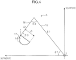
- FIG. 4 is a diagram illustrating the work device 4 in a simplified manner.
- the boom 15 and the arm 16 are each illustrated with a straight line to simplify the description.
- a position and posture of the work device 4 are represented by a three-dimensional coordinate system of the construction machine 1.
- the three-dimensional coordinate system of the construction machine 1 is defined by a Y axis indicating the upper-lower direction, an X axis indicating the front-rear direction, and a Z axis indicating the right-left direction.
- the origin of the Y axis is set, for example, at a proximal end of the boom 15.
- the origin of the X axis is set, for example, on the front surface 31a.
- the origin of the Z axis is set, for example, at a center of the right-left direction of the front surface 31a.
- a length L1 of the boom 15 and a length L2 of the arm 16 are known. Therefore, if a rotation angle ⁇ 1 of the boom 15 and a rotation angle ⁇ 2 of the arm 16 with respect to the boom 15 are known, an X coordinate value and a Y coordinate value of the attachment installation unit r provided at the tip of the arm 16 can be identified. Also, when the posture of the work device 4 changes on a plane parallel to the Y-X plane, a position of the proximal end of the boom 15 in the right-left direction is known, and accordingly, a Z coordinate value of the attachment installation unit r can also be identified.
- the X, Y, Z coordinate values of the attachment installation unit r are known, it can be determined which coordinate in the distance image data measured by the distance sensor 110 corresponds to the attachment installation unit r, from the angle of view, an attaching position, and an angle of an optical axis of the distance sensor 110.
- the attachment 17 is represented by a group of pixel data with depth continuously distributed. Therefore, if the coordinates of the attachment installation unit r in the distance image data are known, by extracting the group of pixel data with the coordinates as a base point, the region indicating the distance distribution indicating the attachment 17 can be extracted from the distance image data.
- the region extraction unit 121 obtains the position of the attachment installation unit r in the three-dimensional coordinate system of the construction machine 1 from the rotation angles ⁇ 1 and ⁇ 2. Through coordinate conversion of the obtained position into the three-dimensional coordinate system of the distance sensor 110, the region extraction unit 121 obtains the coordinates of the attachment installation unit r in the distance image data. Then, the region extraction unit 121 extracts the region of the attachment 17 by extracting the group of pixel data with depth continuously distributed with the attachment installation unit r as a base point.
- the feature amount extraction unit 122 extracts the feature amount of the attachment 17 from the region indicating the distance distribution of the attachment 17 extracted by the region extraction unit 121.
- FIGS. 5 and 6 are explanatory diagrams of a feature amount extraction process.
- FIG. 5 shows a state in which a posture plane A51 defining the posture of the attachment 17 is positioned parallel to a vertical plane A52.
- FIG. 6 shows a state in which the posture plane A51 is positioned at an angle ⁇ with respect to the vertical plane A52.
- the upper-lower direction is described as the Y direction
- the front-rear direction is described as the X direction
- the right-left direction is described as the Z direction.
- the posture plane A51 is a plane passing in a longitudinal direction of the attachment 17 and is a plane orthogonal to an X-Y plane. Note that the angle ⁇ of the posture plane A51 with respect to the vertical plane A52 illustrated in FIG. 6 can be calculated from the rotation angles ⁇ 1 to ⁇ 3.
- the vertical plane A52 is a plane that passes the attachment installation unit r and is orthogonal to the X direction.
- the attachment installation unit r has a depth of Xb and a Y-direction value (altitude) of Yb.
- the feature amount of the attachment 17 is defined by a shape of a surface 171 on a cab 31 side of the attachment 17.
- the shape of the surface 171 is defined by a height of the surface 171 relative to the posture plane A51.
- one line of pixel data group parallel to the Y direction on the surface 171 has depths of (XI, X2,..., Xn).
- the heights of this one line of pixel data group from the posture plane A51 are represented as (X1 - Xb, X2 - Xb,..., Xn - Xb).
- the heights of the posture plane A51 of another line of pixel data group parallel to the Y direction are also represented as (X1-Xb, X2 - Xb,..., Xn - Xb).
- one line of pixel data group parallel to the Y direction on the surface 171 has depths of (X1', X2',..., Xn').
- the posture plane A51 is positioned at the angle ⁇ counterclockwise with respect to the vertical plane A52, (X1' - Xb, X2' - Xb,..., Xn' - Xb) do not represent the heights from the posture plane A51.
- the pixel data group having the depths of (X1', X2',..., Xn') is rotated clockwise by the angle ⁇ around the attachment installation unit r to obtain (X1'_ ⁇ , X2'_ ⁇ ,..., Xn'_ ⁇ ). Then, since the posture plane A51 agrees with the vertical plane A52, (X1'_ ⁇ - Xb, X2'_ ⁇ - Xb, ..., Xn'_ ⁇ - Xb) represents the heights of the surface 171 relative to the posture plane A51.
- the feature amount extraction unit 122 first calculates the angle ⁇ by using the rotation angles ⁇ 1 to ⁇ 3. Next, all lines of pixel data group parallel to the Y direction indicating the surface 171 of the attachment 17 extracted by the region extraction unit 121 are rotated by an angle (- ⁇ ) by rotation matrix calculation around the attachment installation unit r on the X-Y plane.
- the feature amount (X1", X2",..., Xn") indicates the heights of the attachment 17 from the posture plane A51.
- the database 130 stores the heights of the surface 171 of the reference attachment with respect to the posture plane A51 as the feature amount of the reference attachment. Therefore, the feature amount of the attachment 17 (X1", X2",..., Xn") can be compared with the feature amount of the reference attachment stored in the database 130.
- the feature amount extraction unit 122 rotates all lines of pixel data group parallel to the Y direction. However, if the feature amount of the reference attachment includes one line of data parallel to the Y direction, the feature amount extraction unit 122 may rotate only one line of pixel data group parallel to the Y direction.
- the attachment recognition unit 123 compares the feature amount extracted by the feature amount extraction unit 122 with the feature amount of one or more reference attachments stored in the database 130 to recognize the attachment 17. Specifically, the attachment recognition unit 123 calculates similarity between the feature amount of the attachment 17 (X1", X2",..., Xn") and the feature amount of each reference attachment stored in the database 130. The attachment recognition unit 123 recognizes the reference attachment having similarity equal to or greater than reference similarity and having the maximum similarity, as an attachment of the same type as the attachment 17.
- the attachment recognition unit 123 may calculate the similarity by using the Jaccard coefficient or the Dice coefficient that allows calculation of similarity between three-dimensional point groups.
- the posture control unit 124 controls the posture of the work device 4 so as to take a posture according to the operation amount output from the operation unit 150. Also, for example, the posture control unit 124 detects a distance from the cab 31 to the interference object by using the posture of the work device 4 detected by the posture detection unit 100 and the distance image data measured by the distance sensor 110. When the distance becomes equal to or less than a reference distance, the posture control unit 124 performs interference prevention control for controlling the work device 4 to prevent the interference object from interfering with the cab 31. Also, when the distance from the cab 31 to the interference object becomes equal to or less than the reference distance, the posture control unit 124 notifies the operator of danger of interference by using the notification unit 140.
- the database 130 stores the feature amount of one or more reference attachments in advance.
- FIG. 3 is a diagram conceptually illustrating the feature amount of the reference attachment stored in the database 130.
- the database 130 stores the feature amount of various attachments such as a bucket, a breaker, and a nibbler.
- heights of the surface 171 with respect to the posture plane A51 H1, H2,..., Hn are employed as the feature amount of the reference attachment.
- the feature amount extraction unit 122 rotates the pixel data group (X1, X2,..., Xn) by the angle (- ⁇ ) to calculate the feature amount of the attachment 17, but the present invention is not limited to this example.
- the feature amount extraction unit 122 may extract the pixel data group (X1 - Xb, X2 - Xb,..., Xn - Xb) as the feature amount of the attachment 17.
- the attachment recognition unit 123 may rotate the reference attachment by the angle ⁇ , and compare the feature amount of the rotated reference attachment with the feature amount of the attachment 17.
- the attachment recognition unit 123 rotates the reference attachment by the angle ⁇ with respect to the vertical plane A52 about a base point P17 as a rotation center to make the posture of the reference attachment the same as the posture of the attachment 17. Then, the attachment recognition unit 123 may determine the height of each position of the rotated surface 171 from the vertical plane A52 and compare the height with the feature amount of the attachment 17. Note that the base point P17 indicates the installation position in the attachment installation unit r.
- the notification unit 140 includes a buzzer, a display panel, and a warning lamp provided inside the cab 31.
- the notification unit 140 issues a warning to the operator under the control of the posture control unit 124.
- the operation unit 150 includes an operation lever for receiving the operator's operation for changing the posture of the work device 4, and a mode setting button for receiving input of a mode setting command by the operator for setting an operation mode of the construction machine 1. Note that if the construction machine 1 includes a touch panel display, the mode setting button may be comprised of the touch panel display.
- the operation lever outputs a signal indicating the operation amount to the controller 120.
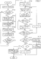
- FIG. 7 is a flowchart illustrating a process of the attachment recognition device according to the first embodiment of the present invention. This flowchart is executed, for example, when the engine 210 of the construction machine 1 starts.
- the posture detection unit 100 detects the posture of the work device 4.
- the region extraction unit 121 determines from the detected posture whether the posture of the work device 4 is within a distance measurable range (S702).
- the region extraction unit 121 may determine that the posture of the work device 4 is within the distance measurable range.
- the region extraction unit 121 may obtain the position of the attachment installation unit r of the arm 16 by using the method described in FIG.
- the region extraction unit 121 prevents measurement of distance image data that does not include the attachment 17.
- the distance sensor 110 acquires the distance image data indicating the distance distribution of a surrounding object of the cab 31 (S703). On the other hand, if the posture of the work device 4 is not within the distance measurable range (NO in S702), the process returns to S701.
- step S704 the region extraction unit 121 obtains the coordinates of the attachment installation unit r in the distance image data by using the posture detected in step S701 (rotation angles ⁇ 1 to ⁇ 3), and then extracts, from the coordinates, a group of pixel data with continuous depth as the region indicating the distance distribution of the attachment 17.
- the feature amount extraction unit 122 calculates the angle ⁇ of the posture plane A51 by using the posture detected in S701 (rotation angles ⁇ 1 to ⁇ 3) (S705).
- the feature amount extraction unit 122 rotates the pixel data group constituting the region extracted in S704 by the angle (- ⁇ ) in X-Y plan view, and extracts the feature amount of the attachment 17 by calculation of (X1_ ⁇ - Xb, X2_ ⁇ -Xb, ..., Xn_ ⁇ - Xb) (S706). Also, in step S706, the feature amount extraction unit 122 averages the extracted feature amount. For example, in the loop from S701 to S707, the feature amount extraction unit 122 calculates the feature amount by adding the feature amount calculated in the current loop to an average value of the feature amount calculated in the loop up to the previous time for averaging. This will provide the feature amount in which an influence of noise and measurement variation is suppressed.
- step S707 if the number of extractions of the feature amount does not reach a predetermined number of times (NO in step S707), the process returns to step S701. On the other hand, if the number of extractions of the feature amount reaches the predetermined number of times (YES in S707), the process proceeds to S708.
- the attachment recognition unit 123 sets a variable n for identifying one reference attachment of interest at an initial value (for example, "0"), sets a variable ind for identifying the reference attachment having the maximum similarity at an initial value, and sets the maximum similarity Smax at the minimum value (for example, "-1") (S708).
- the attachment recognition unit 123 reads a feature amount C (n) of the reference attachment from the database 130 (S709).
- the attachment recognition unit 123 calculates similarity S (n) between the feature amount C (n) and the averaged feature amount calculated in S706, that is, the feature amount of the attachment 17 (S710).
- the attachment recognition unit 123 sets the maximum similarity Smax at the similarity S (n) and sets the variable ind at n (S712).
- the similarity S (n) is not larger than the maximum similarity Smax (NO in S711)
- the process proceeds to S713.
- the similarity S (n) of the reference attachment most similar to the attachment 17 among the reference attachments read up to the present time is stored in the maximum similarity Smax.
- the variable n for identifying the reference attachment most similar to the attachment 17 among the reference attachments read up to the present time is stored in the variable ind.
- the attachment recognition unit 123 increments the variable n by 1 (S714), and the process returns to step S709.
- the feature amount C (n + 1) of the next reference attachment is read from the database 130, and the similarity S (n + 1) between the feature amount C (n + 1) and the feature amount of the attachment 17 is calculated.
- the process proceeds to S715. That is, through the repetition of the process of S709 to S713, the reference attachment which is a candidate for the attachment 17 is determined from among all the reference attachments.
- the attachment recognition unit 123 determines whether the maximum similarity Smax is larger than the reference similarity. If the maximum similarity Smax is larger than the reference similarity (YES in S715), the attachment recognition unit 123 determines that the candidate reference attachment corresponds to the attachment 17, and determines whether the variable ind is equal to the variable ind' currently stored in the memory 130M (S716).
- the attachment recognition unit 123 determines that the attachment 17 has not been changed and causes the notification unit 140 to notify this determination (S718).
- the notification unit 140 may output a message using a voice or image such as "Attachment has not been changed.”
- the attachment recognition unit 123 determines that the attachment 17 has been changed, updates the variable ind' with the variable ind, and causes the notification unit 140 to notify that the attachment 17 has been changed (S717).
- the notification unit 140 may output a message using a voice or image such as "Attachment has been changed.”.
- the reference attachment is recognized as the attachment 17 attached to the work device 4, and interference prevention control and the like are performed.
- the attachment recognition unit 123 determines that the attachment 17 cannot be recognized (S719). This makes it possible to prevent determination that the attachment 17 corresponds to either reference attachment although the attachment of the same type as the attachment 17 has not been stored in the database 130.
- the attachment recognition unit 123 adds the feature amount of the attachment 17 to the database 130 (S720). This causes the new attachment to be registered in the database. This makes it possible to prevent a failure in recognition of the new attachment.
- the attachment recognition device enables recognition of a variety of attachments other than a bucket (for example, a nibbler and a breaker) in a short time without manually inputting identification information about the attachment.
- a second embodiment sets an operation mode of a construction machine 1 as a recognition mode for recognizing an attachment 17. Note that in the present embodiment, the same components as in the first embodiment are denoted with the same reference signs, and the description thereof will be omitted.
- FIG. 8 is a block diagram illustrating a system configuration of an attachment recognition device according to the second embodiment of the present invention.
- FIG. 8 differs from FIG. 2 in that a mode setting unit 125 is added.
- the mode setting unit 125 sets the operation mode of the construction machine 1 as the recognition mode for recognizing the attachment 17.
- the mode setting unit 125 may set the operation mode of the construction machine 1 as the recognition mode when an operator presses a mode setting button included in an operation unit 150.
- a posture control unit 124 controls a control valve 260 such that a posture of a work device 4 becomes a predetermined measurement posture (one example of a specified posture).
- a measurement posture it is possible to employ a posture in which a posture plane A51 of the attachment 17 is parallel to a vertical plane A52. This is because a feature amount of a reference attachment is defined by a height of a surface 171 of the reference attachment relative to the posture plane A51 as illustrated in FIG. 3 .
- a posture in which the posture plane A51 has a certain angle ⁇ with respect to the vertical plane A52 may be employed as the measurement posture.
- a database 130 stores the height of the surface 171 of the reference attachment from the vertical plane A52 when the posture plane A51 is positioned at the angle ⁇ with respect to the vertical plane A52, as the feature amount of the reference attachment.
- the measurement posture may be a posture in which the posture plane A51 is inclined by the angle ⁇ with respect to the vertical plane A52.
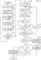
- FIG. 9 is a flowchart illustrating a process of the attachment recognition device according to the second embodiment of the present invention. Note that in FIG. 9 , the same processes as in FIG. 7 are denoted with the same reference signs.
- This flowchart starts when the operation mode is set as the recognition mode.
- the posture control unit 124 controls the control valve 260 such that the posture of the work device 4 becomes the measurement posture (S1101).
- the posture of the work device 4 is controlled at predetermined rotation angles ⁇ 1 to ⁇ 3 such that the posture plane A51 takes a posture that agrees with the vertical plane A52.
- the work device 4 is automatically controlled so as to take the measurement posture.
- the posture control unit 124 may set, as the measurement posture, the posture of the work device 4 at a low speed such that there is no problem even when the work device 4 comes into contact with a human body or a surrounding object.
- the posture control unit 124 may perform reaction force control to move the work device 4 in a direction away from the human body or the surrounding object.
- the posture control unit 124 may cause the operator to operate the operation unit 150 to set the posture of the work device 4 as the measurement posture.
- the posture control unit 124 may notify guidance for setting the posture of the work device 4 as the measurement posture by using a notification unit 140.
- the posture control unit 124 may notify, by using the notification unit 140, that the posture of the work device 4 has become the measurement posture.
- the posture of the work device 4 is set as the measurement posture and the process for recognizing the attachment 17 is executed. This makes it possible to extract the feature amount of the attachment 17 itself and to prevent deterioration in the recognition accuracy of the attachment 17.
- the database 130 is provided in a memory 130M of the construction machine 1; however, the present invention is not limited to this, and the database 130 may be provided in a cloud server.
- the construction machine 1 may include a communication device for communicating with the cloud server.
- the database 130 in the cloud server may be used to recognize the attachment 17.
- the cloud server may be requested to perform a process for recognizing the attachment 17.
- an attachment recognition unit 123 and the database 130 may be provided in the cloud server.
- the construction machine 1 may perform the process until extracting the feature amount of the attachment 17, to transmit extraction results to the cloud server, and to request the cloud server to perform the recognition process of the attachment 17. With this process, more various attachments 17 can be recognized.
- the attachment 17 modified by a user may be attached to the work device 4.
- the database 130 cannot store the feature amount of such an attachment 17 in advance, the attachment 17 may not be recognized permanently.
- interference prevention control and operation control suitable for the attachment 17 are no longer performed. Therefore, in the present embodiment, the process of S720 illustrated in FIGS. 7 and 9 is provided, and the feature amount of the attachment 17 that cannot be recognized is added to the database 130.
- the attachment recognition unit 123 may calculate a size and weight of the attachment from the feature amount of the attachment 17, and store the obtained size and weight together with the feature amount in the database 130.
- a length, width, and depth of a rectangular parallelepiped when a rectangular parallelepiped circumscribed on the attachment 17 is applied can be employed as the size.
- L3 is the length and L4 is the depth.
- the width is the length in a right-left direction (Z direction) of the attachment 17.
- the weight, which is assumed to be the volume of the attachment 17, can be calculated by multiplying density of the attachment 17. This makes it possible to perform interference prevention control and motion control suitable for the attachment 17.
- the database 130 stores only the feature amount of the reference attachment; however, the present invention is not limited to this, and the size and weight of the reference attachment may be stored together with the feature amount.
- the attachment recognition device can obtain the size and weight of the attachment 17 from the database 130, without calculating the size and weight of the attachment 17 from the feature amount of the attachment 17. This makes it possible to perform suitable interference prevention control and motion control according to the size and weight of the attachment 17.
- the attachment recognition unit 123 may obtain the size and weight of the attachment 17 from the feature amount of the attachment 17, and calculate similarity with the reference attachment by including the obtained size and weight in the feature amount. With this calculation, the attachment 17 can be recognized more accurately.
- An attachment recognition device for recognizing an attachment installed in an attachment installation unit in a construction machine including a work device including the attachment installation unit in which a plurality of types of attachment is installed in a replaceable manner.
- the attachment recognition device includes: a posture detection unit configured to detect a posture of the work device; a distance sensor configured to measure distance distribution of a surrounding object including the installed attachment; a region extraction unit configured to extract a region indicating distance distribution of the installed attachment from the distance distribution measured by the distance sensor by using the posture detected by the posture detection unit; a feature amount extraction unit configured to extract a feature amount of the installed attachment from the region extracted by the region extraction unit; a database configured to store a feature amount of one or more types of reference attachment in advance; and an attachment recognition unit configured to make comparison of the feature amount extracted by the feature amount extraction unit and the feature amount of the reference attachment to recognize the installed attachment.
- the region indicating the distance distribution of the attachment is extracted from the distance distribution of the surrounding object including the attachment measured by the distance sensor, by using the posture of the attachment. Then, the feature amount of the attachment is extracted from the extracted region, the extracted feature amount of the attachment is compared with the feature amount of the reference attachment stored in advance in the database, and the installed attachment is recognized.
- this aspect allows recognition of the attachment even if identification information about the attachment is not manually input. Also, since the attachment can be recognized without measuring the attachment before replacement, measurement work can be finished in a short time. Measurement work can also be performed at an arbitrary timing after replacement. By storing the feature amount of various reference attachments in the database, various attachments can be recognized.
- the attachment recognition device may further include: a mode setting unit configured to set an operation mode of the construction machine as a recognition mode for recognizing the installed attachment based on input of a mode setting command; and a posture control unit configured to cause the installed attachment to take a predetermined specified posture when the mode setting unit sets the recognition mode.
- the distance sensor may measure the distance distribution when the posture control unit causes the installed attachment to take the specified posture.
- the distance distribution when the posture control unit causes the attachment to take the specified posture is measured, and the attachment is recognized based on the measured distance distribution. Therefore, recognition errors of the attachment due to information change of the attachment occurring during the operation of the construction machine (for example, a bucket contains earth and sand, a nibbler grasps an object) can be prevented.
- the database may store, as the feature amount, the distance distribution of the reference attachment when the posture of the reference attachment is set as the specified posture.
- the feature amount of the attachment to be recognized can be used as it is for comparison with the feature amount of the reference attachment stored in the database.
- the construction machine may include a main body
- the work device may include a movable unit that is pivotably connected to the main body and is provided with the attachment installation unit at a tip
- the attachment may be pivotably connected to the attachment installation unit
- the feature amount of the reference attachment may be defined by a height of a surface of the reference attachment with respect to a posture plane defining the posture of the reference attachment
- the feature amount extraction unit may rotate the distance distribution extracted by the region extraction unit around the attachment installation unit such that the posture plane defining the posture of the attachment is in a vertical direction
- the feature amount extraction unit may calculate a difference between the rotated distance distribution and a distance of the attachment installation unit as the feature amount.
- the feature amount of the reference attachment is defined by the height of the surface of the reference attachment with respect to the posture plane defining the posture of the reference attachment. Therefore, it is necessary to employ the height of the surface of the attachment with respect to the posture plane as the feature amount of the attachment.
- the difference between the rotated distance distribution of the attachment and the distance of the attachment installation unit represents the height of the surface of the attachment with respect to the posture plane. Therefore, in this aspect, the feature amount of the attachment suitable for comparison with the feature amount of the reference attachment can be calculated by a simple process.
- the attachment recognition unit may add the feature amount of the attachment that is not recognized to the database.
- the feature amount of the attachment to be recognized if the feature amount of the attachment to be recognized has not been stored in the database, the feature amount of the attachment is added to the database, which allows prevention of the attachment from remaining unrecognized. Even when an unexpected attachment is installed by a user, the database can be constructed such that the attachment is recognized.
- the attachment recognition device may further include a notification unit configured to notify a recognition result of the installed attachment by the attachment recognition unit.
Landscapes
- Engineering & Computer Science (AREA)
- Mining & Mineral Resources (AREA)
- Civil Engineering (AREA)
- General Engineering & Computer Science (AREA)
- Structural Engineering (AREA)
- Mechanical Engineering (AREA)
- Computer Vision & Pattern Recognition (AREA)
- Physics & Mathematics (AREA)
- General Physics & Mathematics (AREA)
- Theoretical Computer Science (AREA)
- Quality & Reliability (AREA)
- Component Parts Of Construction Machinery (AREA)
- Image Analysis (AREA)
- Operation Control Of Excavators (AREA)
- Image Processing (AREA)
Claims (6)
- Dispositif de reconnaissance d'accessoire pour reconnaître un accessoire (17) installé dans une unité d'installation d'accessoire (r) dans une machine de construction (1) qui comprend un dispositif de travail (4) qui comprend l'unité d'installation d'accessoire (r) dans laquelle une pluralité de types d'accessoires (17) sont installés de manière remplaçable, dans lequel le dispositif de reconnaissance d'accessoire comprend :une unité de détection de posture (100) configurée pour détecter une posture du dispositif de travail (4) ; un capteur de distance (110) configuré pour acquérir des données d'image de distances d'un objet environnant qui comprend l'accessoire installé ;caractérisé en ce que le dispositif de reconnaissance d'accessoire comprend en outre :une unité d'extraction de région (121) configurée pour extraire une région qui indique une répartition des distances de l'accessoire installé des données d'image de distances acquises par le capteur de distance en utilisant la posture détectée par l'unité de détection de posture (100) ;une unité d'extraction de quantité de caractéristique (122) configurée pour extraire une quantité de caractéristique de l'accessoire installé de la région extraite par l'unité d'extraction de région (121) ;une base de données (130) configurée pour mémoriser une quantité de caractéristique d'un ou de plusieurs types d'accessoires de référence à l'avance ; etune unité de reconnaissance d'accessoire (123) configurée pour effectuer une comparaison entre la quantité de caractéristique extraite par l'unité d'extraction de quantité de caractéristique (122) et la quantité de caractéristique de l'accessoire de référence pour reconnaître l'accessoire installé.
- Dispositif de reconnaissance d'accessoire selon la revendication 1, qui comprend en outre :une unité d'établissement de mode (125) configurée pour établir un mode de fonctionnement de la machine de construction (1) en tant que mode de reconnaissance pour reconnaître l'accessoire installé sur la base de l'entrée d'une commande d'établissement de mode ; etune unité de commande de posture (124) configurée pour amener l'accessoire installé à prendre une posture spécifiée prédéterminée lorsque l'unité d'établissement de mode (125) établit le mode de reconnaissance, dans lequelle capteur de distance (110) acquiert les données d'image de distances lorsque l'unité de commande de posture (124) amène l'accessoire installé à prendre la posture spécifiée.
- Dispositif de reconnaissance d'accessoire selon la revendication 2, dans lequel la base de données (130) mémorise, en tant que quantité de caractéristique, la répartition des distances de l'accessoire de référence lorsque la posture de l'accessoire de référence est établie en tant que posture spécifiée.
- Dispositif de reconnaissance d'accessoire selon la revendication 1, dans lequel
la machine de construction (1) comprend un corps principal,
le dispositif de travail (4) comprend une unité mobile qui est reliée au corps principal de manière pivotante et qui est pourvue de l'unité d'installation d'accessoire (r) à une extrémité,
l'accessoire (17) est relié de manière pivotante à l'unité d'installation d'accessoire (r),
la quantité de caractéristique de l'accessoire de référence est définie par une hauteur d'une surface (171) de l'accessoire de référence par rapport à un plan de posture (A51) qui définit la posture de l'accessoire de référence, et
l'unité d'extraction de quantité de caractéristique (122) fait tourner la répartition des distances extraite par l'unité d'extraction de région (121) autour de l'unité d'installation d'accessoire de sorte que le plan de posture qui définit la posture de l'accessoire installé soit dans une direction verticale, et l'unité d'extraction de quantité de caractéristique (122) calcule une différence entre la répartition des distances tournée et une distance de l'unité d'installation d'accessoire (r) en tant que quantité de caractéristique. - Dispositif de reconnaissance d'accessoire selon l'une quelconque des revendications 1 à 4, dans lequel, lorsque l'accessoire installé n'a pas pu être reconnu même avec la comparaison, l'unité de reconnaissance d'accessoire (123) ajoute la quantité de caractéristique de l'accessoire installé à la base de données.
- Dispositif de reconnaissance d'accessoire selon l'une quelconque des revendications 1 à 5, qui comprend en outre une unité de notification (140) configurée pour notifier un résultat de reconnaissance de l'accessoire installé par l'unité de reconnaissance d'accessoire (123).
Applications Claiming Priority (2)
| Application Number | Priority Date | Filing Date | Title |
|---|---|---|---|
| JP2016040044A JP6681747B2 (ja) | 2016-03-02 | 2016-03-02 | アタッチメント認識装置 |
| PCT/JP2017/004837 WO2017150134A1 (fr) | 2016-03-02 | 2017-02-10 | Dispositif de reconnaissance d"accessoire |
Publications (3)
| Publication Number | Publication Date |
|---|---|
| EP3409848A1 EP3409848A1 (fr) | 2018-12-05 |
| EP3409848A4 EP3409848A4 (fr) | 2019-03-20 |
| EP3409848B1 true EP3409848B1 (fr) | 2020-04-08 |
Family
ID=59744016
Family Applications (1)
| Application Number | Title | Priority Date | Filing Date |
|---|---|---|---|
| EP17759605.3A Not-in-force EP3409848B1 (fr) | 2016-03-02 | 2017-02-10 | Dispositif de reconnaissance d"accessoire |
Country Status (5)
| Country | Link |
|---|---|
| US (1) | US10676900B2 (fr) |
| EP (1) | EP3409848B1 (fr) |
| JP (1) | JP6681747B2 (fr) |
| CN (1) | CN108713083B (fr) |
| WO (1) | WO2017150134A1 (fr) |
Families Citing this family (23)
| Publication number | Priority date | Publication date | Assignee | Title |
|---|---|---|---|---|
| KR102157285B1 (ko) * | 2016-11-09 | 2020-09-17 | 가부시키가이샤 고마쓰 세이사쿠쇼 | 작업 차량 및 작업 차량의 제어 방법 |
| CN111183260B (zh) * | 2017-10-05 | 2023-02-03 | 沃尔沃建筑设备公司 | 具有附接装置的工程机械和用于监控附接装置的附接状态的系统 |
| JP7114907B2 (ja) * | 2018-01-19 | 2022-08-09 | コベルコ建機株式会社 | 先端アタッチメント判別装置 |
| JP6954145B2 (ja) * | 2018-01-19 | 2021-10-27 | コベルコ建機株式会社 | 先端アタッチメント寸法計測装置 |
| JP6942671B2 (ja) | 2018-04-26 | 2021-09-29 | 株式会社小松製作所 | 寸法特定装置および寸法特定方法 |
| JP7082906B2 (ja) | 2018-05-28 | 2022-06-09 | 株式会社小松製作所 | 制御装置および制御方法 |
| US11041291B2 (en) * | 2018-09-14 | 2021-06-22 | Deere & Company | Controlling a work machine based on sensed variables |
| EP3859088A4 (fr) * | 2018-09-27 | 2022-01-26 | Sumitomo Heavy Industries, Ltd. | Pelle et dispositif de traitement d'informations |
| US10776949B2 (en) | 2018-10-30 | 2020-09-15 | Liberty Reach Inc. | Machine vision-based method and system for measuring 3D pose of a part or subassembly of parts |
| US11286641B2 (en) * | 2018-12-07 | 2022-03-29 | Deere & Company | Attachment-configurable system for a work machine |
| JP6961641B2 (ja) * | 2019-03-26 | 2021-11-05 | 日立建機株式会社 | 建設機械アタッチメントの管理システム及び管理サーバ |
| JP7439053B2 (ja) | 2019-03-27 | 2024-02-27 | 住友重機械工業株式会社 | ショベル及びショベルの管理装置 |
| CN113939630B (zh) | 2019-04-05 | 2023-09-22 | 沃尔沃建筑设备公司 | 建筑设备 |
| WO2020239205A1 (fr) * | 2019-05-28 | 2020-12-03 | Volvo Construction Equipment Ab | Procédé mis en œuvre par ordinateur pour le suivi des outils de travail sur un site de travail |
| US11204254B2 (en) * | 2019-05-29 | 2021-12-21 | Deere & Company | Implement guidance display system for work vehicles |
| US11615707B2 (en) | 2019-05-29 | 2023-03-28 | Deere & Company | Guidance display system for work vehicles and work implements |
| JP7624291B2 (ja) * | 2019-05-31 | 2025-01-30 | 株式会社小松製作所 | マップ生成システム及びマップ生成方法 |
| KR102402254B1 (ko) * | 2020-01-20 | 2022-05-26 | 현대두산인프라코어 주식회사 | 휠 로더의 제어 시스템 및 방법 |
| WO2021193450A1 (fr) * | 2020-03-25 | 2021-09-30 | 住友重機械工業株式会社 | Machine de construction, système de gestion pour machine de construction, dispositif d'apprentissage automatique et système de gestion pour site de travail de machine de construction |
| JP7452473B2 (ja) * | 2021-03-08 | 2024-03-19 | コベルコ建機株式会社 | 容器計測システム |
| DE102021212627A1 (de) | 2021-11-10 | 2023-05-11 | Robert Bosch Gesellschaft mit beschränkter Haftung | Verfahren zum Identifizieren eines Anbaugeräts einer mobilen Arbeitsmaschine |
| JP2025006626A (ja) * | 2023-06-29 | 2025-01-17 | 株式会社クボタ | 作業車両に接続された作業機を推定する方法およびシステム |
| JP2025117600A (ja) * | 2024-01-31 | 2025-08-13 | ヤンマーホールディングス株式会社 | 作業車両の制御方法、作業車両制御プログラム、作業車両制御システム及び作業車両 |
Family Cites Families (10)
| Publication number | Priority date | Publication date | Assignee | Title |
|---|---|---|---|---|
| JP3224066B2 (ja) * | 1994-03-28 | 2001-10-29 | 株式会社小松製作所 | 建設機械のアタッチメント数値データ測定方法 |
| JP2004294067A (ja) * | 2003-03-25 | 2004-10-21 | Penta Ocean Constr Co Ltd | 無人化施工装置 |
| JP2005248502A (ja) * | 2004-03-03 | 2005-09-15 | Hitachi Constr Mach Co Ltd | 作業機の干渉防止装置 |
| US6990390B2 (en) | 2004-05-19 | 2006-01-24 | Caterpillar Inc. | Method and apparatus to detect change in work tool |
| JP2009197438A (ja) * | 2008-02-20 | 2009-09-03 | Caterpillar Japan Ltd | 作業機械における干渉防止制御装置 |
| JP4931955B2 (ja) * | 2009-04-06 | 2012-05-16 | 日立建機株式会社 | 油圧ショベルの油圧回路装置 |
| JP2012233353A (ja) * | 2011-05-02 | 2012-11-29 | Komatsu Ltd | 油圧ショベルの較正システム及び油圧ショベルの較正方法 |
| JP5806690B2 (ja) * | 2013-02-01 | 2015-11-10 | 株式会社小松製作所 | 作業機械の管理装置 |
| WO2014123228A1 (fr) * | 2013-02-08 | 2014-08-14 | 日立建機株式会社 | Dispositif de surveillance d'environs pour un engin de chantier du type orientable |
| JP6538315B2 (ja) | 2014-06-26 | 2019-07-03 | 住友建機株式会社 | ショベル |
-
2016
- 2016-03-02 JP JP2016040044A patent/JP6681747B2/ja active Active
-
2017
- 2017-02-10 WO PCT/JP2017/004837 patent/WO2017150134A1/fr not_active Ceased
- 2017-02-10 CN CN201780014169.4A patent/CN108713083B/zh not_active Expired - Fee Related
- 2017-02-10 EP EP17759605.3A patent/EP3409848B1/fr not_active Not-in-force
- 2017-02-10 US US16/081,143 patent/US10676900B2/en not_active Expired - Fee Related
Non-Patent Citations (1)
| Title |
|---|
| None * |
Also Published As
| Publication number | Publication date |
|---|---|
| JP2017157016A (ja) | 2017-09-07 |
| US20190093321A1 (en) | 2019-03-28 |
| EP3409848A4 (fr) | 2019-03-20 |
| EP3409848A1 (fr) | 2018-12-05 |
| CN108713083B (zh) | 2021-03-09 |
| US10676900B2 (en) | 2020-06-09 |
| JP6681747B2 (ja) | 2020-04-15 |
| CN108713083A (zh) | 2018-10-26 |
| WO2017150134A1 (fr) | 2017-09-08 |
Similar Documents
| Publication | Publication Date | Title |
|---|---|---|
| EP3409848B1 (fr) | Dispositif de reconnaissance d"accessoire | |
| US11111654B2 (en) | Interference prevention device for construction machinery | |
| US12571183B2 (en) | Excavator | |
| US10907324B2 (en) | Construction machine | |
| US11028553B2 (en) | Construction machine | |
| CN113631779A (zh) | 挖土机及施工系统 | |
| US11462030B2 (en) | Method and system for detecting a pile | |
| CN114508135A (zh) | 一种无人操作挖掘机及控制方法 | |
| CN111108251A (zh) | 检测装置及工程机械 | |
| EP3757299B1 (fr) | Appareil de génération de données d'environnement autour d'équipement de construction et équipement de construction le comprenant | |
| US20200347579A1 (en) | Tip attachment discrimination device | |
| CN115163107A (zh) | 截割臂控制方法、装置、掘进机及掘进机控制系统 | |
| EP4421249B1 (fr) | Étalonnage de véhicule d'exploitation minière | |
| EP4421250B1 (fr) | Étalonnage de véhicule d'exploitation minière | |
| KR20260047246A (ko) | 전력 제어 시스템 및 전력 제어 방법 |
Legal Events
| Date | Code | Title | Description |
|---|---|---|---|
| STAA | Information on the status of an ep patent application or granted ep patent |
Free format text: STATUS: THE INTERNATIONAL PUBLICATION HAS BEEN MADE |
|
| PUAI | Public reference made under article 153(3) epc to a published international application that has entered the european phase |
Free format text: ORIGINAL CODE: 0009012 |
|
| STAA | Information on the status of an ep patent application or granted ep patent |
Free format text: STATUS: REQUEST FOR EXAMINATION WAS MADE |
|
| 17P | Request for examination filed |
Effective date: 20180831 |
|
| AK | Designated contracting states |
Kind code of ref document: A1 Designated state(s): AL AT BE BG CH CY CZ DE DK EE ES FI FR GB GR HR HU IE IS IT LI LT LU LV MC MK MT NL NO PL PT RO RS SE SI SK SM TR |
|
| AX | Request for extension of the european patent |
Extension state: BA ME |
|
| A4 | Supplementary search report drawn up and despatched |
Effective date: 20190218 |
|
| RIC1 | Information provided on ipc code assigned before grant |
Ipc: G06T 7/00 20170101ALI20190212BHEP Ipc: E02F 3/96 20060101ALI20190212BHEP Ipc: E02F 9/26 20060101ALI20190212BHEP Ipc: E02F 9/24 20060101AFI20190212BHEP Ipc: E02F 3/36 20060101ALI20190212BHEP |
|
| DAV | Request for validation of the european patent (deleted) | ||
| DAX | Request for extension of the european patent (deleted) | ||
| GRAP | Despatch of communication of intention to grant a patent |
Free format text: ORIGINAL CODE: EPIDOSNIGR1 |
|
| STAA | Information on the status of an ep patent application or granted ep patent |
Free format text: STATUS: GRANT OF PATENT IS INTENDED |
|
| INTG | Intention to grant announced |
Effective date: 20190829 |
|
| GRAS | Grant fee paid |
Free format text: ORIGINAL CODE: EPIDOSNIGR3 |
|
| GRAA | (expected) grant |
Free format text: ORIGINAL CODE: 0009210 |
|
| STAA | Information on the status of an ep patent application or granted ep patent |
Free format text: STATUS: THE PATENT HAS BEEN GRANTED |
|
| AK | Designated contracting states |
Kind code of ref document: B1 Designated state(s): AL AT BE BG CH CY CZ DE DK EE ES FI FR GB GR HR HU IE IS IT LI LT LU LV MC MK MT NL NO PL PT RO RS SE SI SK SM TR |
|
| REG | Reference to a national code |
Ref country code: AT Ref legal event code: REF Ref document number: 1254558 Country of ref document: AT Kind code of ref document: T Effective date: 20200415 Ref country code: CH Ref legal event code: EP |
|
| REG | Reference to a national code |
Ref country code: DE Ref legal event code: R096 Ref document number: 602017014540 Country of ref document: DE |
|
| REG | Reference to a national code |
Ref country code: IE Ref legal event code: FG4D |
|
| REG | Reference to a national code |
Ref country code: NL Ref legal event code: MP Effective date: 20200408 |
|
| REG | Reference to a national code |
Ref country code: LT Ref legal event code: MG4D |
|
| PG25 | Lapsed in a contracting state [announced via postgrant information from national office to epo] |
Ref country code: SE Free format text: LAPSE BECAUSE OF FAILURE TO SUBMIT A TRANSLATION OF THE DESCRIPTION OR TO PAY THE FEE WITHIN THE PRESCRIBED TIME-LIMIT Effective date: 20200408 Ref country code: PT Free format text: LAPSE BECAUSE OF FAILURE TO SUBMIT A TRANSLATION OF THE DESCRIPTION OR TO PAY THE FEE WITHIN THE PRESCRIBED TIME-LIMIT Effective date: 20200817 Ref country code: NL Free format text: LAPSE BECAUSE OF FAILURE TO SUBMIT A TRANSLATION OF THE DESCRIPTION OR TO PAY THE FEE WITHIN THE PRESCRIBED TIME-LIMIT Effective date: 20200408 Ref country code: IS Free format text: LAPSE BECAUSE OF FAILURE TO SUBMIT A TRANSLATION OF THE DESCRIPTION OR TO PAY THE FEE WITHIN THE PRESCRIBED TIME-LIMIT Effective date: 20200808 Ref country code: NO Free format text: LAPSE BECAUSE OF FAILURE TO SUBMIT A TRANSLATION OF THE DESCRIPTION OR TO PAY THE FEE WITHIN THE PRESCRIBED TIME-LIMIT Effective date: 20200708 Ref country code: LT Free format text: LAPSE BECAUSE OF FAILURE TO SUBMIT A TRANSLATION OF THE DESCRIPTION OR TO PAY THE FEE WITHIN THE PRESCRIBED TIME-LIMIT Effective date: 20200408 Ref country code: FI Free format text: LAPSE BECAUSE OF FAILURE TO SUBMIT A TRANSLATION OF THE DESCRIPTION OR TO PAY THE FEE WITHIN THE PRESCRIBED TIME-LIMIT Effective date: 20200408 Ref country code: GR Free format text: LAPSE BECAUSE OF FAILURE TO SUBMIT A TRANSLATION OF THE DESCRIPTION OR TO PAY THE FEE WITHIN THE PRESCRIBED TIME-LIMIT Effective date: 20200709 |
|
| REG | Reference to a national code |
Ref country code: AT Ref legal event code: MK05 Ref document number: 1254558 Country of ref document: AT Kind code of ref document: T Effective date: 20200408 |
|
| PG25 | Lapsed in a contracting state [announced via postgrant information from national office to epo] |
Ref country code: BG Free format text: LAPSE BECAUSE OF FAILURE TO SUBMIT A TRANSLATION OF THE DESCRIPTION OR TO PAY THE FEE WITHIN THE PRESCRIBED TIME-LIMIT Effective date: 20200708 Ref country code: LV Free format text: LAPSE BECAUSE OF FAILURE TO SUBMIT A TRANSLATION OF THE DESCRIPTION OR TO PAY THE FEE WITHIN THE PRESCRIBED TIME-LIMIT Effective date: 20200408 Ref country code: RS Free format text: LAPSE BECAUSE OF FAILURE TO SUBMIT A TRANSLATION OF THE DESCRIPTION OR TO PAY THE FEE WITHIN THE PRESCRIBED TIME-LIMIT Effective date: 20200408 Ref country code: HR Free format text: LAPSE BECAUSE OF FAILURE TO SUBMIT A TRANSLATION OF THE DESCRIPTION OR TO PAY THE FEE WITHIN THE PRESCRIBED TIME-LIMIT Effective date: 20200408 |
|
| PG25 | Lapsed in a contracting state [announced via postgrant information from national office to epo] |
Ref country code: AL Free format text: LAPSE BECAUSE OF FAILURE TO SUBMIT A TRANSLATION OF THE DESCRIPTION OR TO PAY THE FEE WITHIN THE PRESCRIBED TIME-LIMIT Effective date: 20200408 |
|
| REG | Reference to a national code |
Ref country code: DE Ref legal event code: R097 Ref document number: 602017014540 Country of ref document: DE |
|
| PG25 | Lapsed in a contracting state [announced via postgrant information from national office to epo] |
Ref country code: SM Free format text: LAPSE BECAUSE OF FAILURE TO SUBMIT A TRANSLATION OF THE DESCRIPTION OR TO PAY THE FEE WITHIN THE PRESCRIBED TIME-LIMIT Effective date: 20200408 Ref country code: EE Free format text: LAPSE BECAUSE OF FAILURE TO SUBMIT A TRANSLATION OF THE DESCRIPTION OR TO PAY THE FEE WITHIN THE PRESCRIBED TIME-LIMIT Effective date: 20200408 Ref country code: DK Free format text: LAPSE BECAUSE OF FAILURE TO SUBMIT A TRANSLATION OF THE DESCRIPTION OR TO PAY THE FEE WITHIN THE PRESCRIBED TIME-LIMIT Effective date: 20200408 Ref country code: RO Free format text: LAPSE BECAUSE OF FAILURE TO SUBMIT A TRANSLATION OF THE DESCRIPTION OR TO PAY THE FEE WITHIN THE PRESCRIBED TIME-LIMIT Effective date: 20200408 Ref country code: AT Free format text: LAPSE BECAUSE OF FAILURE TO SUBMIT A TRANSLATION OF THE DESCRIPTION OR TO PAY THE FEE WITHIN THE PRESCRIBED TIME-LIMIT Effective date: 20200408 Ref country code: CZ Free format text: LAPSE BECAUSE OF FAILURE TO SUBMIT A TRANSLATION OF THE DESCRIPTION OR TO PAY THE FEE WITHIN THE PRESCRIBED TIME-LIMIT Effective date: 20200408 Ref country code: ES Free format text: LAPSE BECAUSE OF FAILURE TO SUBMIT A TRANSLATION OF THE DESCRIPTION OR TO PAY THE FEE WITHIN THE PRESCRIBED TIME-LIMIT Effective date: 20200408 |
|
| PLBE | No opposition filed within time limit |
Free format text: ORIGINAL CODE: 0009261 |
|
| STAA | Information on the status of an ep patent application or granted ep patent |
Free format text: STATUS: NO OPPOSITION FILED WITHIN TIME LIMIT |
|
| PG25 | Lapsed in a contracting state [announced via postgrant information from national office to epo] |
Ref country code: SK Free format text: LAPSE BECAUSE OF FAILURE TO SUBMIT A TRANSLATION OF THE DESCRIPTION OR TO PAY THE FEE WITHIN THE PRESCRIBED TIME-LIMIT Effective date: 20200408 Ref country code: PL Free format text: LAPSE BECAUSE OF FAILURE TO SUBMIT A TRANSLATION OF THE DESCRIPTION OR TO PAY THE FEE WITHIN THE PRESCRIBED TIME-LIMIT Effective date: 20200408 |
|
| 26N | No opposition filed |
Effective date: 20210112 |
|
| PG25 | Lapsed in a contracting state [announced via postgrant information from national office to epo] |
Ref country code: SI Free format text: LAPSE BECAUSE OF FAILURE TO SUBMIT A TRANSLATION OF THE DESCRIPTION OR TO PAY THE FEE WITHIN THE PRESCRIBED TIME-LIMIT Effective date: 20200408 |
|
| PG25 | Lapsed in a contracting state [announced via postgrant information from national office to epo] |
Ref country code: MC Free format text: LAPSE BECAUSE OF FAILURE TO SUBMIT A TRANSLATION OF THE DESCRIPTION OR TO PAY THE FEE WITHIN THE PRESCRIBED TIME-LIMIT Effective date: 20200408 |
|
| REG | Reference to a national code |
Ref country code: BE Ref legal event code: MM Effective date: 20210228 |
|
| PG25 | Lapsed in a contracting state [announced via postgrant information from national office to epo] |
Ref country code: CH Free format text: LAPSE BECAUSE OF NON-PAYMENT OF DUE FEES Effective date: 20210228 Ref country code: LI Free format text: LAPSE BECAUSE OF NON-PAYMENT OF DUE FEES Effective date: 20210228 Ref country code: LU Free format text: LAPSE BECAUSE OF NON-PAYMENT OF DUE FEES Effective date: 20210210 |
|
| PG25 | Lapsed in a contracting state [announced via postgrant information from national office to epo] |
Ref country code: IE Free format text: LAPSE BECAUSE OF NON-PAYMENT OF DUE FEES Effective date: 20210210 |
|
| PGFP | Annual fee paid to national office [announced via postgrant information from national office to epo] |
Ref country code: GB Payment date: 20211231 Year of fee payment: 6 |
|
| PGFP | Annual fee paid to national office [announced via postgrant information from national office to epo] |
Ref country code: DE Payment date: 20211230 Year of fee payment: 6 |
|
| PGFP | Annual fee paid to national office [announced via postgrant information from national office to epo] |
Ref country code: IT Payment date: 20220111 Year of fee payment: 6 Ref country code: FR Payment date: 20220118 Year of fee payment: 6 |
|
| PG25 | Lapsed in a contracting state [announced via postgrant information from national office to epo] |
Ref country code: BE Free format text: LAPSE BECAUSE OF NON-PAYMENT OF DUE FEES Effective date: 20210228 |
|
| PG25 | Lapsed in a contracting state [announced via postgrant information from national office to epo] |
Ref country code: CY Free format text: LAPSE BECAUSE OF FAILURE TO SUBMIT A TRANSLATION OF THE DESCRIPTION OR TO PAY THE FEE WITHIN THE PRESCRIBED TIME-LIMIT Effective date: 20200408 |
|
| PG25 | Lapsed in a contracting state [announced via postgrant information from national office to epo] |
Ref country code: HU Free format text: LAPSE BECAUSE OF FAILURE TO SUBMIT A TRANSLATION OF THE DESCRIPTION OR TO PAY THE FEE WITHIN THE PRESCRIBED TIME-LIMIT; INVALID AB INITIO Effective date: 20170210 |
|
| REG | Reference to a national code |
Ref country code: DE Ref legal event code: R119 Ref document number: 602017014540 Country of ref document: DE |
|
| GBPC | Gb: european patent ceased through non-payment of renewal fee |
Effective date: 20230210 |
|
| PG25 | Lapsed in a contracting state [announced via postgrant information from national office to epo] |
Ref country code: GB Free format text: LAPSE BECAUSE OF NON-PAYMENT OF DUE FEES Effective date: 20230210 |
|
| PG25 | Lapsed in a contracting state [announced via postgrant information from national office to epo] |
Ref country code: IT Free format text: LAPSE BECAUSE OF NON-PAYMENT OF DUE FEES Effective date: 20230210 Ref country code: GB Free format text: LAPSE BECAUSE OF NON-PAYMENT OF DUE FEES Effective date: 20230210 Ref country code: FR Free format text: LAPSE BECAUSE OF NON-PAYMENT OF DUE FEES Effective date: 20230228 Ref country code: DE Free format text: LAPSE BECAUSE OF NON-PAYMENT OF DUE FEES Effective date: 20230901 |
|
| PG25 | Lapsed in a contracting state [announced via postgrant information from national office to epo] |
Ref country code: MK Free format text: LAPSE BECAUSE OF FAILURE TO SUBMIT A TRANSLATION OF THE DESCRIPTION OR TO PAY THE FEE WITHIN THE PRESCRIBED TIME-LIMIT Effective date: 20200408 |
|
| PG25 | Lapsed in a contracting state [announced via postgrant information from national office to epo] |
Ref country code: TR Free format text: LAPSE BECAUSE OF FAILURE TO SUBMIT A TRANSLATION OF THE DESCRIPTION OR TO PAY THE FEE WITHIN THE PRESCRIBED TIME-LIMIT Effective date: 20200408 |
|
| PG25 | Lapsed in a contracting state [announced via postgrant information from national office to epo] |
Ref country code: MT Free format text: LAPSE BECAUSE OF FAILURE TO SUBMIT A TRANSLATION OF THE DESCRIPTION OR TO PAY THE FEE WITHIN THE PRESCRIBED TIME-LIMIT Effective date: 20200408 |