EP3409873A1 - Spannseilmontagevorrichtung für eine architektonische abdeckung - Google Patents
Spannseilmontagevorrichtung für eine architektonische abdeckung Download PDFInfo
- Publication number
- EP3409873A1 EP3409873A1 EP17174055.8A EP17174055A EP3409873A1 EP 3409873 A1 EP3409873 A1 EP 3409873A1 EP 17174055 A EP17174055 A EP 17174055A EP 3409873 A1 EP3409873 A1 EP 3409873A1
- Authority
- EP
- European Patent Office
- Prior art keywords
- cord
- tension
- holder
- base
- cord holder
- Prior art date
- Legal status (The legal status is an assumption and is not a legal conclusion. Google has not performed a legal analysis and makes no representation as to the accuracy of the status listed.)
- Granted
Links
Images




Classifications
-
- E—FIXED CONSTRUCTIONS
- E06—DOORS, WINDOWS, SHUTTERS, OR ROLLER BLINDS IN GENERAL; LADDERS
- E06B—FIXED OR MOVABLE CLOSURES FOR OPENINGS IN BUILDINGS, VEHICLES, FENCES OR LIKE ENCLOSURES IN GENERAL, e.g. DOORS, WINDOWS, BLINDS, GATES
- E06B9/00—Screening or protective devices for wall or similar openings, with or without operating or securing mechanisms; Closures of similar construction
- E06B9/24—Screens or other constructions affording protection against light, especially against sunshine; Similar screens for privacy or appearance; Slat blinds
- E06B9/26—Lamellar or like blinds, e.g. venetian blinds
- E06B9/266—Devices or accessories for making or mounting lamellar blinds or parts thereof
-
- E—FIXED CONSTRUCTIONS
- E06—DOORS, WINDOWS, SHUTTERS, OR ROLLER BLINDS IN GENERAL; LADDERS
- E06B—FIXED OR MOVABLE CLOSURES FOR OPENINGS IN BUILDINGS, VEHICLES, FENCES OR LIKE ENCLOSURES IN GENERAL, e.g. DOORS, WINDOWS, BLINDS, GATES
- E06B9/00—Screening or protective devices for wall or similar openings, with or without operating or securing mechanisms; Closures of similar construction
- E06B9/24—Screens or other constructions affording protection against light, especially against sunshine; Similar screens for privacy or appearance; Slat blinds
- E06B9/26—Lamellar or like blinds, e.g. venetian blinds
- E06B9/28—Lamellar or like blinds, e.g. venetian blinds with horizontal lamellae, e.g. non-liftable
- E06B9/30—Lamellar or like blinds, e.g. venetian blinds with horizontal lamellae, e.g. non-liftable liftable
- E06B9/32—Operating, guiding, or securing devices therefor
- E06B9/327—Guides for raisable lamellar blinds with horizontal lamellae
Definitions
- the following relates to a tension cord mounting, in particular a mounting for tension cords of an architectural covering to be held in place with respect to at and an outside edge of an architectural structure, such as a window opening or a door opening.
- EP 1 526 246 A describes a mounting device for a guide cord. Two such mounting devices are used on opposite respective sides of a lower periphery of an architectural structure to secure the cords used for the downwardly extending blind.
- a tension cord mounting for an architectural covering configured to be mounted to an outside edge of an architectural structure, the tension cord mounting including:
- a tension cord of an architectural covering to the periphery of an architectural structure by using a tension cord mounting having a cord holder, the method including:
- the tension cord mounting may be embodied in an architectural covering for example as illustrated schematically in Fig. 1 .
- the architectural covering may be fitted to an architectural structure 101 and includes an upper movable rail 102 and a lower movable rail 104.
- a shade 106 of any appropriate form extends between the upper movable rail 102 and the lower movable rail 104.
- one or both of the rails may be fixed.
- the architectural covering may include at least a third rail. It general, it should be appreciated that the tension cord mounting may be applicable to any architectural covering in which a cord is engaged under tension.
- the shade 106 may take the form of a roman shade, a venetian blind, a cellular structure etc.
- Each of the upper movable rail 102 and lower movable rail 104 is movable across the architectural structure 101 towards and away from a respective edge. As the upper movable rail 102 and lower movable rail 104 move towards each other, the shade 106 is retracted, for example by concertina, stacking or rolling action. When the upper movable rail 102 and lower movable rail 104 are moved apart, the shade 106 is extended across the architectural structure 101.
- cords 108 extend parallel to the side edges of the architectural structure 101 and along the respective movable rails 102, 104.
- the cords 108 are mounted to the upper and lower sides of the architectural opening by means of tension cord mountings 110 that are secured to those edges of the architectural structure 101.
- the tension cord mounting disclosed herein includes a cord holder for engaging one or more cords.
- the cord holder includes a plurality of walls arranged in fixed positions relative to one another that together define a pathway for the one or more cords along and/or through the cord holder.
- the pathway is configured such that, when a cord is placed within the pathway, the cord includes at least one change of direction and is arranged such that, when the cord is under tension, friction between the cord and the walls of the cord holder engages the cord with the cord holder.
- the section of cord under tension may not move in an axial direction relative to the cord holder.
- cord holder when the cord is under tension, flexure of the cord holder may result in some movement of the walls of the cord holder relative to each other.
- provision of a cord holder that in a single element can secure the one or more cords rather than, for example, provision of two elements that must be moved relative to each other and/or attached to each other in order to secure the cord may be beneficial. For example, it may be easier for a user to attach a cord to such a cord holder formed from a single element and/or adjust the position of the cord once it is secured to such a cord holder.
- the cord holder may be integrally formed as a single component.
- the cord holder walls may be configured such that the pathway defines changes of direction of the one or more cords when located within the pathway in the cord holder that include at least two inflection points.
- the cord when the cord is within the pathway defined by the walls, the cord is arranged in a curve that includes at least two points at which the curve changes from being concave to convex or vice-versa.
- Fig. 2 depicts an example of such a cord holder 201, in this case engaging one cord 202. It should be appreciated, however, that cord holders as here described may be configured to engage a different number of cords, such as for example, two, three or four cords.
- Fig. 3 depicts in plan view such a cord holder 201 without any cords and
- Fig. 4 depicts in cross-section the shape of a cord 202 when within the pathway defined by a cord holder 201 and engaged with the cord holder 201.
- the cord holder 201 may include a plurality of walls 210, 211, 212, 213, 214, 215, 216 that define a pathway with multiple changes of direction of a cord 202 when the cord is within the pathway. Some of the walls of the cord holder 201 define spaces between the walls through which a cord 202 within the pathway must pass, namely define a section of the pathway. Other sections of the pathway of the cord 202 are defined by the one or more walls providing fixed separation between such spaces.
- a first pair of walls 211, 212 define a first space 221 through which a cord 202 within the pathway must pass.
- a second pair of walls 213, 214 define a second space 222 through which a cord 202 within the pathway must pass.
- a wall 216 separates the first and second spaces 221, 222.
- a cord 202 placed within the pathway is arranged by the configuration of the walls to include multiple sections.
- the cord 202 is bent from an initial direction to pass through the first space 221.
- the cord 202 is constrained to be oriented in a direction parallel to the surfaces of the first pair of walls 211,212.
- the cord 202 is bent towards the second space 222 defined by second pair of walls.
- the cord 202 passes along the wall 216 in a direction parallel to the surface of the wall 216.
- the cord 202 is bent to pass through the second space 222.
- the cord 202 is constrained to be oriented in a direction parallel to the surfaces of the second pair of walls 213, 214.
- the cord 202 is bent away from the second space towards the remainder of the pathway.
- the sections 224, 228 of a cord 202 within the pathway defined by the walls of the cord holder 201, which are located between sections of the cord at which it is bent, namely changes direction, may be inflection points.
- the cord holder 201 may be thinner than the arrangement shown such that at least walls 211, 212, 213,214 are shorter than in the arrangement shown.
- the sections 224, 228 of the cord 202 adjacent the walls 211, 212, 213, 214 may become so short that, in effect, no length of the cord is parallel to the walls 221, 212, 213, 214 and there is just a point at which the cord changes direction.
- the length of the wall 216 may be reduced such that the section 226 of the cord 202 adjacent the wall 216 becomes so short that, in effect, it becomes just a point at which the cord changes direction.
- the changes of direction of the cord are such that the tension of the cord 202 itself creates a contact pressure between the cord 202 and the cord holder 201.
- the tension in the cord 202 at the first and second points of inflection 221, 222 draws the section 223 of cord between the inflection points 221, 222 onto the wall 216 that is between the first pair of walls 211, 212 and the second pair of walls 213, 214.
- the contact pressure establishes friction between the cord holder 201 and the cord 202.
- the number and extent of changes of direction of the cord pathway may vary.
- the number and extent of the changes of direction that are required to engage a particular cord 202 reliably with a particular cord holder 201 may depend on the coefficient of friction between the cord holder 201 and the cord 202.
- Fig. 5 depicts the arrangement of a cord 202 during adjustment of the position of the cord 202 on a cord holder 201.
- a section of the cord may be pulled away from the cord holder 201.
- the section 226 of cord between the two sections 224, 228 that pass through first and second spaces 221, 222 may be drawn up to form an extended loop.
- This cord may be drawn from either a first end 235 or a second end 236 of the cord 202.
- the other end 235, 236 of the cord 202 may be gently pulled to draw the section 226 of cord 202 back to its tensioned position against the wall 216 of the cord holder 201.
- the cord holder 201 may be engaged with the cord 202 in the new position relative to the cord 202. Accordingly, with such an arrangement, the position of the cord holder 201 and cord 202 may be adjusted relative to each other by a simple method without requiring any tools, for example. In arrangements in which more than one cord 202 are engaged with the cord holder 201, multiple cords may be adjusted simultaneously and/or each cord may be adjusted separately.
- the cord 202 may be engaged with the cord holder 201 without tools.
- the cord 202 may be drawn in sections along the pathway of the cord 202 through the cord holder 201, taking care as each section is drawn along to pull though spare cord in loops in order to avoid the cord becoming fully tensioned and therefore becoming engaged with the cord holder.
- the cord holder walls may be arranged such that at each point along the pathway for the cords, the cords can be placed into the pathway by a movement of the cords in a direction that is at an angle to the direction of the cord at that location, transverse to the length of the cord. For example, this may include being able to insert the cord into the pathway in a direction that is locally perpendicular to the direction in which the cords extend.
- the cord 202 can be placed in the section of the pathway between the pair of walls 211, 212 by passing a section of the cord 202 through a gap 231 that extends in a direction perpendicular to the direction in which the section of the cord extends, from outside the cord holder 201 to the space between the pair of walls 211, 212 that defines that section of the pathway.
- a gap 232 is provided that enables a section of cord 202 to be moved into the space between the pair of walls 213, 214 in a direction that is perpendicular to the direction in which the cord 202 extends when it is located in that section of the pathway.
- gaps 231, 232 permit insertion of the cord 202 into the spaces 221, 222 at least in a direction perpendicular to the direction in which the cord extends
- the gaps 231, 232 also permit the cord 202 to be inserted into the spaces 221, 222 at a variety of other angles relative to the local direction in which the cord 202 extends.
- Such an arrangement namely one in which the cord 202 can be introduced to sections of the pathway through the cord holder 201 in a direction at an angle to the direction in which the cord extends within that section of the pathway, namely not along the direction of the cord, may facilitate engaging the cord 202 with the cord holder 201.
- a motion may be easier for users than threading the cord 202 lengthways through the pathway, which may be required in the absence of such an arrangement.
- the cord holder 201 is configured such that the direction in which a cord 202 must be moved in order insert it between a first pair of walls 211, 212 is opposite to the direction in which the cord 202 must be moved in order to insert a separate section of cord between the second pair of walls 213, 214.
- Other arrangements may be provided.
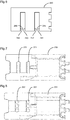
- Fig. 6 depicts a cord holder 240 that is similar to the cord holder 201 depicted in Fig. 3 , having a first pair of walls 241, 242 and a second pair of walls 243, 244 that each define a part of a pathway for the cord 202 having an inflection point.
- the corresponding gaps 245, 246 to enable the placement of the cord 202 within the pathway are provided on the same side of the cord holder 240, such that the cord can be inserted into both the space between the first pair of walls 241, 242 and the second pair of walls 243, 244 in the same direction.
- a cord holder may be used that does not have gaps permitting the cord to be placed in the pathway defined in the cord holder in a direction transverse to the cord.
- Figs 7 and 8 depict arrangements of cord holders 250, 251 in which the openings into the spaces 221, 222 are provided in the direction of the cord.
- an end of the cord may be inserted into the spaces 221, 222 in order to place the cord within the pathway defined by the cord holder 250, 251.
- the openings into such spaces may be sufficiently large that a plurality of cords can be passed into each such space.
- Fig. 7 in an arrangement, the openings into such spaces may be sufficiently large that a plurality of cords can be passed into each such space.
- a mixed arrangement may also be provided, in which at one point in the pathway defined by the cord holder, plural cords pass through a single space but, at another point in the pathway defined by the cord holder, respective spaces are provided for each cord.
- the cord holder 201 may include one or more restrictions 251, 252, 253 that are configured to loosely constrain the cord 202 to the pathway.
- the restrictions 251, 252, 253 may not significantly contribute to the tension of the cord 202 that can be held by the cord holder 201. However, they may be sufficiently strong to temporarily bear the weight of the cord. Accordingly, as a user is attempting to engage the cord 202 with the cord holder 201, the restrictions 251, 252, 253 may hold part of the cord 202 in place while the user is positioning another section of the cord 202 within the pathway.
- the tension cord mounting as described here may also include a base.
- the base may be configured to be mounted to an outside edge of the architectural structure and the cord holder may be configured to be detachably coupled to the base.
- This construction may facilitate mounting the cord to the architectural structure.
- the cord holder may be configured such that it can be mounted directly to the architectural structure. For example it may include an aperture arranged such a fixing such as a screw or bolt can mount the cord holder to the architectural structure.
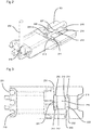
- Fig. 9 depicts an exploded view of an example of a combination of a cord holder 201 and a base 260.
- the base 260 may be mounted to an edge of an architectural structure, such as a window opening or door opening such as by way of a fastener such as a screw 261.
- a fastener such as a screw 261 may engage directly with the base 260
- a clamp 262 is provided which engages with the screw 261 and holds the base 260 in place against the architectural structure.
- the clamp may include one or more teeth 263 that, in use, extend through the lower surface of the base 260 to engage with the surface of the architectural structure, ensuring that the base 260 does not slide on the surface of the architectural structure.
- the user may mount the base 260 to the architectural structure. Separately, the user may provide a cord to a pathway defined by the walls of a tension cord holder and place the cord under tension in order to engage the cord with the cord holder. Thereafter, the user may couple the cord holder to the base in order to mount the tension cord to the architectural structure. Separating the actions of mounting a component to the architectural structure on the one hand and engaging the cord with a component on the other hand may make these actions easier for the user.
- the user may disengage the cord holder from the base, adjust the position of the cord holder relative to the tension cord and then re-couple the cord holder to the base. As will be apparent, to do so the user does not require any tools. Alternatively or additionally, the user may be able to adjust the position of the cord relative to the cord holder while the cord holder remains coupled to the base.
- the cord holder and the base may be coupled to each other by at least one of a fastener and a snap-fit connection.
- a fastener any suitable conventionally known fastener may be used including, for example, a screw and/or a bolt fastening. Other arrangements may be used.
- the cord holder 201 and base 260 are configured such that the first end 271 of the cord holder 201 couples to the first end 272 of the base 260 and the second end 273 of the cord holder 201 couples to the second end 274 of the base 260.
- the structure to couple the first ends 271, 272 of the cord holder 201 and base 260 are different from the structure to couple the second ends 273, 274 of the cord holder 201 and base 260.
- the first end 271 of the cord holder 201 includes protrusions 275 that are configured to engage with recesses 276 at the first end 272 of the base 260. It should be appreciated that this arrangement may be reversed, namely the first end 272 of the base may have protrusions that fit into corresponding recesses at the first end 271 of the cord holder 201.
- respective snap-fit elements 277, 278 may be provided.
- Fig. 10 shows a tension cord mounting of this arrangement after the cord holder 201 has been coupled to the base 260.
- the cord holder 201 may be arranged such that the cords 202 that extend from the tension cord mounting under tension extend from the first end 271 of the cord holder 202, namely adjacent the coupling formed from the protrusions 275 engaging with the corresponding recesses 276.
- Such an arrangement may be beneficial because such a coupling may be better able to withstand the tension within the cord 202 than, for example, snap-fit connections.
- the at least one protrusion 275 may extend from the first end 271 of the cord holder 201 (or in an arrangement not shown in the figures from the base) in a direction perpendicular to the direction in which the one or more tension cords 202 extend under tension. Accordingly, when the one or more protrusions 275 are inserted in the corresponding recesses 276, the force exerted by the tension of the one or more cords acts in a direction perpendicular to the insertion direction, namely does not act in a direction to push the protrusion from its recess.
- the user may first insert the protrusions 275 of the cord holder 201 into the recesses 276 of the base 260 with the cord holder 201 at a slight angle relative to the base 260.
- the user may press down on the second end 273 of the cord holder 201 in order to engage the snap-fit connectors 277, 278 at the second ends 273, 274 of the cord holder 201 and base 260.
- the engagement of the protrusions 275 within the recesses 276 provides a strong resistance to the tension of the cords 202.
- the snap-fit connection at the second ends 273, 274 of the cord holder 201 and base 260 prevent the cord holder 201 moving relative to the base 260 in a direction that would disengage the protrusions 275 from the recesses 276.
- the snap-fit connection does not need to be strong enough to resist the tension of the cord.
- the user may disengage the snap-fit connectors 277, 278 at the second ends 273, 274 of the cord holder 201 and base 260 using a force that is less than the tension within the one or more cords 202 and then disengage the protrusions 275 from the recesses 276.
- a cover 280 may be provided that detachably couples to one or both of the cord holder 201 and the base 260.
- a cover may have a snap-fit connection to one or both of the cord holder 201 and the base 260.
- one of the cover and the component to which it is to be connected may have ridges that engage with grooves in the other of the cover and component to which it is to be connected, arranged such that the cover can be coupled by sliding it into place.
- the cover 280 may conceal the free ends of the one or more cords that are engaged with the cord holder 201, namely the ends other than the ends of the cord 202 that extend from the tension cord mounting under tension.
- the cover 280 may hold the free ends of the cord 202 in a desired position relative to the cord holder 201, for example, against a wall 215 that defines one end of the pathway of the cord 202 within the cord holder 201.
- All directional references e.g., proximal, distal, upper, lower, upward, downward, left, right, lateral, longitudinal, front, back, top, bottom, above, below, vertical, horizontal, radial, axial, clockwise, counterclockwise, and/or the like
- proximal, distal, upper, lower, upward, downward, left, right, lateral, longitudinal, front, back, top, bottom, above, below, vertical, horizontal, radial, axial, clockwise, counterclockwise, and/or the like are only used for identification purposes to aid the reader's understanding of the present disclosure, and / or serve to distinguish regions of the associated elements from one another, and do not limit the associated element, particularly as to the position, orientation, or use of this disclosure.
Landscapes
- Engineering & Computer Science (AREA)
- Structural Engineering (AREA)
- Architecture (AREA)
- Civil Engineering (AREA)
- Blinds (AREA)
Priority Applications (1)
| Application Number | Priority Date | Filing Date | Title |
|---|---|---|---|
| EP17174055.8A EP3409873B1 (de) | 2017-06-01 | 2017-06-01 | Spannseilmontagevorrichtung für eine architektonische abdeckung |
Applications Claiming Priority (1)
| Application Number | Priority Date | Filing Date | Title |
|---|---|---|---|
| EP17174055.8A EP3409873B1 (de) | 2017-06-01 | 2017-06-01 | Spannseilmontagevorrichtung für eine architektonische abdeckung |
Publications (2)
| Publication Number | Publication Date |
|---|---|
| EP3409873A1 true EP3409873A1 (de) | 2018-12-05 |
| EP3409873B1 EP3409873B1 (de) | 2021-05-05 |
Family
ID=59021353
Family Applications (1)
| Application Number | Title | Priority Date | Filing Date |
|---|---|---|---|
| EP17174055.8A Active EP3409873B1 (de) | 2017-06-01 | 2017-06-01 | Spannseilmontagevorrichtung für eine architektonische abdeckung |
Country Status (1)
| Country | Link |
|---|---|
| EP (1) | EP3409873B1 (de) |
Cited By (2)
| Publication number | Priority date | Publication date | Assignee | Title |
|---|---|---|---|---|
| GB2613138A (en) * | 2021-09-24 | 2023-05-31 | Manchester Mfg Group Ltd | Window blinds |
| US20230332463A1 (en) * | 2022-04-15 | 2023-10-19 | Ingo Scholz | Child safe tension corded shade |
Citations (4)
| Publication number | Priority date | Publication date | Assignee | Title |
|---|---|---|---|---|
| EP1526246A2 (de) | 2003-10-24 | 2005-04-27 | Hunter Douglas Industries B.V. | Montagevorrichtung für ein Führungsseil |
| DE102005029066A1 (de) * | 2004-07-14 | 2006-02-16 | Warema Kunststofftechnik Und Maschinenbau Gmbh | Montageelement |
| EP1783315A2 (de) * | 2005-11-03 | 2007-05-09 | VKR Holding A/S | Schnurhalter und Endkappe für eine Verschattungsanlage sowie Verschattungsanlage |
| US20160290039A1 (en) * | 2014-01-31 | 2016-10-06 | Lutron Electronics Co., Inc. | Cable guided shade system |
-
2017
- 2017-06-01 EP EP17174055.8A patent/EP3409873B1/de active Active
Patent Citations (4)
| Publication number | Priority date | Publication date | Assignee | Title |
|---|---|---|---|---|
| EP1526246A2 (de) | 2003-10-24 | 2005-04-27 | Hunter Douglas Industries B.V. | Montagevorrichtung für ein Führungsseil |
| DE102005029066A1 (de) * | 2004-07-14 | 2006-02-16 | Warema Kunststofftechnik Und Maschinenbau Gmbh | Montageelement |
| EP1783315A2 (de) * | 2005-11-03 | 2007-05-09 | VKR Holding A/S | Schnurhalter und Endkappe für eine Verschattungsanlage sowie Verschattungsanlage |
| US20160290039A1 (en) * | 2014-01-31 | 2016-10-06 | Lutron Electronics Co., Inc. | Cable guided shade system |
Cited By (4)
| Publication number | Priority date | Publication date | Assignee | Title |
|---|---|---|---|---|
| GB2613138A (en) * | 2021-09-24 | 2023-05-31 | Manchester Mfg Group Ltd | Window blinds |
| US20230332463A1 (en) * | 2022-04-15 | 2023-10-19 | Ingo Scholz | Child safe tension corded shade |
| US12312861B2 (en) * | 2022-04-15 | 2025-05-27 | Ingo Scholz | Child safe tension corded shade |
| US12366113B2 (en) * | 2022-04-15 | 2025-07-22 | Ingo Scholz | Child safe tension corded shade |
Also Published As
| Publication number | Publication date |
|---|---|
| EP3409873B1 (de) | 2021-05-05 |
Similar Documents
| Publication | Publication Date | Title |
|---|---|---|
| JP6141337B2 (ja) | レールを取り付ける装置およびスクリーンシステムを設置する方法 | |
| US8028965B2 (en) | Adjustable bracket for a slide assembly | |
| US10173312B2 (en) | Architectural covering with repositionable handle assembly | |
| EP2774519A1 (de) | Duschtüranordnung | |
| US10641038B2 (en) | Rail for an architectural opening covering | |
| JP6228506B2 (ja) | スクリーン装置 | |
| EP2774518A1 (de) | Duschtüranordnung | |
| EP3058846B1 (de) | Zarge für schublade mit einschiebbarem wandelement | |
| US20080303399A1 (en) | Front installing drawer pulling force adjusting apparatus | |
| WO2009098433A1 (en) | Screen system with a bracket for mounting a guiding rail | |
| EP3409873A1 (de) | Spannseilmontagevorrichtung für eine architektonische abdeckung | |
| CN110883509A (zh) | 用于将电子设备免工具地附接到轨条的装配系统 | |
| EP1911620A1 (de) | Abschattungssystem für einen transparenten Bereich eines Kraftfahrzeugdaches und Kraftfahrzeug | |
| CA2964990A1 (en) | Mounting arrangement | |
| EP2256283A2 (de) | Fensterabdeckungen | |
| EP2985403A1 (de) | Rahmen zur montage an einer gebäudestruktur | |
| EP3330476A1 (de) | Spannseilmontage | |
| GB2503934A (en) | Guide rail with reinforcing member for a window screen | |
| EP3333353B1 (de) | Seitenschiene für eine architektonische abdeckung | |
| EP3385492A1 (de) | Schnurhalterung | |
| US20160278549A1 (en) | Slideable Picture Hook Assembly | |
| JP6700890B2 (ja) | 日射遮蔽装置 | |
| AU2013211549A1 (en) | Bottom bar for roller blind or the like, and method for connecting a roller covering to a bottom bar | |
| AU2023251396A1 (en) | Device for capturing a line | |
| EP2474681A1 (de) | Blendenvorrichtung und verfahren zur installation des gehäuses einer derartigen blendenvorrichtung |
Legal Events
| Date | Code | Title | Description |
|---|---|---|---|
| PUAI | Public reference made under article 153(3) epc to a published international application that has entered the european phase |
Free format text: ORIGINAL CODE: 0009012 |
|
| STAA | Information on the status of an ep patent application or granted ep patent |
Free format text: STATUS: THE APPLICATION HAS BEEN PUBLISHED |
|
| AK | Designated contracting states |
Kind code of ref document: A1 Designated state(s): AL AT BE BG CH CY CZ DE DK EE ES FI FR GB GR HR HU IE IS IT LI LT LU LV MC MK MT NL NO PL PT RO RS SE SI SK SM TR |
|
| AX | Request for extension of the european patent |
Extension state: BA ME |
|
| STAA | Information on the status of an ep patent application or granted ep patent |
Free format text: STATUS: REQUEST FOR EXAMINATION WAS MADE |
|
| 17P | Request for examination filed |
Effective date: 20190528 |
|
| RBV | Designated contracting states (corrected) |
Designated state(s): AL AT BE BG CH CY CZ DE DK EE ES FI FR GB GR HR HU IE IS IT LI LT LU LV MC MK MT NL NO PL PT RO RS SE SI SK SM TR |
|
| STAA | Information on the status of an ep patent application or granted ep patent |
Free format text: STATUS: EXAMINATION IS IN PROGRESS |
|
| 17Q | First examination report despatched |
Effective date: 20191212 |
|
| GRAP | Despatch of communication of intention to grant a patent |
Free format text: ORIGINAL CODE: EPIDOSNIGR1 |
|
| STAA | Information on the status of an ep patent application or granted ep patent |
Free format text: STATUS: GRANT OF PATENT IS INTENDED |
|
| INTG | Intention to grant announced |
Effective date: 20201209 |
|
| GRAS | Grant fee paid |
Free format text: ORIGINAL CODE: EPIDOSNIGR3 |
|
| GRAA | (expected) grant |
Free format text: ORIGINAL CODE: 0009210 |
|
| STAA | Information on the status of an ep patent application or granted ep patent |
Free format text: STATUS: THE PATENT HAS BEEN GRANTED |
|
| AK | Designated contracting states |
Kind code of ref document: B1 Designated state(s): AL AT BE BG CH CY CZ DE DK EE ES FI FR GB GR HR HU IE IS IT LI LT LU LV MC MK MT NL NO PL PT RO RS SE SI SK SM TR |
|
| REG | Reference to a national code |
Ref country code: GB Ref legal event code: FG4D |
|
| REG | Reference to a national code |
Ref country code: CH Ref legal event code: EP |
|
| REG | Reference to a national code |
Ref country code: AT Ref legal event code: REF Ref document number: 1390019 Country of ref document: AT Kind code of ref document: T Effective date: 20210515 |
|
| REG | Reference to a national code |
Ref country code: IE Ref legal event code: FG4D |
|
| REG | Reference to a national code |
Ref country code: DE Ref legal event code: R096 Ref document number: 602017037930 Country of ref document: DE |
|
| REG | Reference to a national code |
Ref country code: NL Ref legal event code: FP |
|
| REG | Reference to a national code |
Ref country code: LT Ref legal event code: MG9D |
|
| REG | Reference to a national code |
Ref country code: AT Ref legal event code: MK05 Ref document number: 1390019 Country of ref document: AT Kind code of ref document: T Effective date: 20210505 |
|
| PG25 | Lapsed in a contracting state [announced via postgrant information from national office to epo] |
Ref country code: FI Free format text: LAPSE BECAUSE OF FAILURE TO SUBMIT A TRANSLATION OF THE DESCRIPTION OR TO PAY THE FEE WITHIN THE PRESCRIBED TIME-LIMIT Effective date: 20210505 Ref country code: LT Free format text: LAPSE BECAUSE OF FAILURE TO SUBMIT A TRANSLATION OF THE DESCRIPTION OR TO PAY THE FEE WITHIN THE PRESCRIBED TIME-LIMIT Effective date: 20210505 Ref country code: AT Free format text: LAPSE BECAUSE OF FAILURE TO SUBMIT A TRANSLATION OF THE DESCRIPTION OR TO PAY THE FEE WITHIN THE PRESCRIBED TIME-LIMIT Effective date: 20210505 Ref country code: BG Free format text: LAPSE BECAUSE OF FAILURE TO SUBMIT A TRANSLATION OF THE DESCRIPTION OR TO PAY THE FEE WITHIN THE PRESCRIBED TIME-LIMIT Effective date: 20210805 Ref country code: HR Free format text: LAPSE BECAUSE OF FAILURE TO SUBMIT A TRANSLATION OF THE DESCRIPTION OR TO PAY THE FEE WITHIN THE PRESCRIBED TIME-LIMIT Effective date: 20210505 |
|
| PG25 | Lapsed in a contracting state [announced via postgrant information from national office to epo] |
Ref country code: PL Free format text: LAPSE BECAUSE OF FAILURE TO SUBMIT A TRANSLATION OF THE DESCRIPTION OR TO PAY THE FEE WITHIN THE PRESCRIBED TIME-LIMIT Effective date: 20210505 Ref country code: PT Free format text: LAPSE BECAUSE OF FAILURE TO SUBMIT A TRANSLATION OF THE DESCRIPTION OR TO PAY THE FEE WITHIN THE PRESCRIBED TIME-LIMIT Effective date: 20210906 Ref country code: NO Free format text: LAPSE BECAUSE OF FAILURE TO SUBMIT A TRANSLATION OF THE DESCRIPTION OR TO PAY THE FEE WITHIN THE PRESCRIBED TIME-LIMIT Effective date: 20210805 Ref country code: SE Free format text: LAPSE BECAUSE OF FAILURE TO SUBMIT A TRANSLATION OF THE DESCRIPTION OR TO PAY THE FEE WITHIN THE PRESCRIBED TIME-LIMIT Effective date: 20210505 Ref country code: RS Free format text: LAPSE BECAUSE OF FAILURE TO SUBMIT A TRANSLATION OF THE DESCRIPTION OR TO PAY THE FEE WITHIN THE PRESCRIBED TIME-LIMIT Effective date: 20210505 Ref country code: IS Free format text: LAPSE BECAUSE OF FAILURE TO SUBMIT A TRANSLATION OF THE DESCRIPTION OR TO PAY THE FEE WITHIN THE PRESCRIBED TIME-LIMIT Effective date: 20210905 Ref country code: LV Free format text: LAPSE BECAUSE OF FAILURE TO SUBMIT A TRANSLATION OF THE DESCRIPTION OR TO PAY THE FEE WITHIN THE PRESCRIBED TIME-LIMIT Effective date: 20210505 Ref country code: GR Free format text: LAPSE BECAUSE OF FAILURE TO SUBMIT A TRANSLATION OF THE DESCRIPTION OR TO PAY THE FEE WITHIN THE PRESCRIBED TIME-LIMIT Effective date: 20210806 |
|
| PG25 | Lapsed in a contracting state [announced via postgrant information from national office to epo] |
Ref country code: SK Free format text: LAPSE BECAUSE OF FAILURE TO SUBMIT A TRANSLATION OF THE DESCRIPTION OR TO PAY THE FEE WITHIN THE PRESCRIBED TIME-LIMIT Effective date: 20210505 Ref country code: SM Free format text: LAPSE BECAUSE OF FAILURE TO SUBMIT A TRANSLATION OF THE DESCRIPTION OR TO PAY THE FEE WITHIN THE PRESCRIBED TIME-LIMIT Effective date: 20210505 Ref country code: RO Free format text: LAPSE BECAUSE OF FAILURE TO SUBMIT A TRANSLATION OF THE DESCRIPTION OR TO PAY THE FEE WITHIN THE PRESCRIBED TIME-LIMIT Effective date: 20210505 Ref country code: ES Free format text: LAPSE BECAUSE OF FAILURE TO SUBMIT A TRANSLATION OF THE DESCRIPTION OR TO PAY THE FEE WITHIN THE PRESCRIBED TIME-LIMIT Effective date: 20210505 Ref country code: CZ Free format text: LAPSE BECAUSE OF FAILURE TO SUBMIT A TRANSLATION OF THE DESCRIPTION OR TO PAY THE FEE WITHIN THE PRESCRIBED TIME-LIMIT Effective date: 20210505 Ref country code: DK Free format text: LAPSE BECAUSE OF FAILURE TO SUBMIT A TRANSLATION OF THE DESCRIPTION OR TO PAY THE FEE WITHIN THE PRESCRIBED TIME-LIMIT Effective date: 20210505 Ref country code: EE Free format text: LAPSE BECAUSE OF FAILURE TO SUBMIT A TRANSLATION OF THE DESCRIPTION OR TO PAY THE FEE WITHIN THE PRESCRIBED TIME-LIMIT Effective date: 20210505 |
|
| REG | Reference to a national code |
Ref country code: CH Ref legal event code: PL |
|
| REG | Reference to a national code |
Ref country code: DE Ref legal event code: R097 Ref document number: 602017037930 Country of ref document: DE |
|
| REG | Reference to a national code |
Ref country code: BE Ref legal event code: MM Effective date: 20210630 |
|
| PLBE | No opposition filed within time limit |
Free format text: ORIGINAL CODE: 0009261 |
|
| STAA | Information on the status of an ep patent application or granted ep patent |
Free format text: STATUS: NO OPPOSITION FILED WITHIN TIME LIMIT |
|
| PG25 | Lapsed in a contracting state [announced via postgrant information from national office to epo] |
Ref country code: MC Free format text: LAPSE BECAUSE OF FAILURE TO SUBMIT A TRANSLATION OF THE DESCRIPTION OR TO PAY THE FEE WITHIN THE PRESCRIBED TIME-LIMIT Effective date: 20210505 Ref country code: LU Free format text: LAPSE BECAUSE OF NON-PAYMENT OF DUE FEES Effective date: 20210601 |
|
| 26N | No opposition filed |
Effective date: 20220208 |
|
| GBPC | Gb: european patent ceased through non-payment of renewal fee |
Effective date: 20210805 |
|
| PG25 | Lapsed in a contracting state [announced via postgrant information from national office to epo] |
Ref country code: LI Free format text: LAPSE BECAUSE OF NON-PAYMENT OF DUE FEES Effective date: 20210630 Ref country code: IE Free format text: LAPSE BECAUSE OF NON-PAYMENT OF DUE FEES Effective date: 20210601 Ref country code: CH Free format text: LAPSE BECAUSE OF NON-PAYMENT OF DUE FEES Effective date: 20210630 |
|
| PG25 | Lapsed in a contracting state [announced via postgrant information from national office to epo] |
Ref country code: IS Free format text: LAPSE BECAUSE OF FAILURE TO SUBMIT A TRANSLATION OF THE DESCRIPTION OR TO PAY THE FEE WITHIN THE PRESCRIBED TIME-LIMIT Effective date: 20210905 Ref country code: FR Free format text: LAPSE BECAUSE OF NON-PAYMENT OF DUE FEES Effective date: 20210705 Ref country code: AL Free format text: LAPSE BECAUSE OF FAILURE TO SUBMIT A TRANSLATION OF THE DESCRIPTION OR TO PAY THE FEE WITHIN THE PRESCRIBED TIME-LIMIT Effective date: 20210505 |
|
| PG25 | Lapsed in a contracting state [announced via postgrant information from national office to epo] |
Ref country code: IT Free format text: LAPSE BECAUSE OF FAILURE TO SUBMIT A TRANSLATION OF THE DESCRIPTION OR TO PAY THE FEE WITHIN THE PRESCRIBED TIME-LIMIT Effective date: 20210505 Ref country code: GB Free format text: LAPSE BECAUSE OF NON-PAYMENT OF DUE FEES Effective date: 20210805 Ref country code: BE Free format text: LAPSE BECAUSE OF NON-PAYMENT OF DUE FEES Effective date: 20210630 |
|
| P01 | Opt-out of the competence of the unified patent court (upc) registered |
Effective date: 20230331 |
|
| PG25 | Lapsed in a contracting state [announced via postgrant information from national office to epo] |
Ref country code: CY Free format text: LAPSE BECAUSE OF FAILURE TO SUBMIT A TRANSLATION OF THE DESCRIPTION OR TO PAY THE FEE WITHIN THE PRESCRIBED TIME-LIMIT Effective date: 20210505 |
|
| PG25 | Lapsed in a contracting state [announced via postgrant information from national office to epo] |
Ref country code: HU Free format text: LAPSE BECAUSE OF FAILURE TO SUBMIT A TRANSLATION OF THE DESCRIPTION OR TO PAY THE FEE WITHIN THE PRESCRIBED TIME-LIMIT; INVALID AB INITIO Effective date: 20170601 |
|
| PG25 | Lapsed in a contracting state [announced via postgrant information from national office to epo] |
Ref country code: MK Free format text: LAPSE BECAUSE OF FAILURE TO SUBMIT A TRANSLATION OF THE DESCRIPTION OR TO PAY THE FEE WITHIN THE PRESCRIBED TIME-LIMIT Effective date: 20210505 |
|
| PG25 | Lapsed in a contracting state [announced via postgrant information from national office to epo] |
Ref country code: MT Free format text: LAPSE BECAUSE OF FAILURE TO SUBMIT A TRANSLATION OF THE DESCRIPTION OR TO PAY THE FEE WITHIN THE PRESCRIBED TIME-LIMIT Effective date: 20210505 |
|
| PGFP | Annual fee paid to national office [announced via postgrant information from national office to epo] |
Ref country code: DE Payment date: 20250626 Year of fee payment: 9 |
|
| PGFP | Annual fee paid to national office [announced via postgrant information from national office to epo] |
Ref country code: NL Payment date: 20250624 Year of fee payment: 9 |
|
| PG25 | Lapsed in a contracting state [announced via postgrant information from national office to epo] |
Ref country code: TR Free format text: LAPSE BECAUSE OF FAILURE TO SUBMIT A TRANSLATION OF THE DESCRIPTION OR TO PAY THE FEE WITHIN THE PRESCRIBED TIME-LIMIT Effective date: 20210505 |