EP3409890B1 - Composant destiné à être utilisé dans la voie de gaz chaud d'un moteur à turbine à gaz - Google Patents
Composant destiné à être utilisé dans la voie de gaz chaud d'un moteur à turbine à gaz Download PDFInfo
- Publication number
- EP3409890B1 EP3409890B1 EP18173988.9A EP18173988A EP3409890B1 EP 3409890 B1 EP3409890 B1 EP 3409890B1 EP 18173988 A EP18173988 A EP 18173988A EP 3409890 B1 EP3409890 B1 EP 3409890B1
- Authority
- EP
- European Patent Office
- Prior art keywords
- cooling
- pathway
- primary
- component
- pathways
- Prior art date
- Legal status (The legal status is an assumption and is not a legal conclusion. Google has not performed a legal analysis and makes no representation as to the accuracy of the status listed.)
- Active
Links
Images






Classifications
-
- F—MECHANICAL ENGINEERING; LIGHTING; HEATING; WEAPONS; BLASTING
- F01—MACHINES OR ENGINES IN GENERAL; ENGINE PLANTS IN GENERAL; STEAM ENGINES
- F01D—NON-POSITIVE DISPLACEMENT MACHINES OR ENGINES, e.g. STEAM TURBINES
- F01D5/00—Blades; Blade-carrying members; Heating, heat-insulating, cooling or antivibration means on the blades or the members
- F01D5/12—Blades
- F01D5/14—Form or construction
- F01D5/18—Hollow blades, i.e. blades with cooling or heating channels or cavities; Heating, heat-insulating or cooling means on blades
- F01D5/186—Film cooling
-
- F—MECHANICAL ENGINEERING; LIGHTING; HEATING; WEAPONS; BLASTING
- F01—MACHINES OR ENGINES IN GENERAL; ENGINE PLANTS IN GENERAL; STEAM ENGINES
- F01D—NON-POSITIVE DISPLACEMENT MACHINES OR ENGINES, e.g. STEAM TURBINES
- F01D5/00—Blades; Blade-carrying members; Heating, heat-insulating, cooling or antivibration means on the blades or the members
- F01D5/12—Blades
- F01D5/14—Form or construction
- F01D5/18—Hollow blades, i.e. blades with cooling or heating channels or cavities; Heating, heat-insulating or cooling means on blades
- F01D5/187—Convection cooling
-
- F—MECHANICAL ENGINEERING; LIGHTING; HEATING; WEAPONS; BLASTING
- F01—MACHINES OR ENGINES IN GENERAL; ENGINE PLANTS IN GENERAL; STEAM ENGINES
- F01D—NON-POSITIVE DISPLACEMENT MACHINES OR ENGINES, e.g. STEAM TURBINES
- F01D5/00—Blades; Blade-carrying members; Heating, heat-insulating, cooling or antivibration means on the blades or the members
- F01D5/12—Blades
- F01D5/14—Form or construction
- F01D5/18—Hollow blades, i.e. blades with cooling or heating channels or cavities; Heating, heat-insulating or cooling means on blades
-
- F—MECHANICAL ENGINEERING; LIGHTING; HEATING; WEAPONS; BLASTING
- F01—MACHINES OR ENGINES IN GENERAL; ENGINE PLANTS IN GENERAL; STEAM ENGINES
- F01D—NON-POSITIVE DISPLACEMENT MACHINES OR ENGINES, e.g. STEAM TURBINES
- F01D25/00—Component parts, details, or accessories, not provided for in, or of interest apart from, other groups
- F01D25/08—Cooling; Heating; Heat-insulation
- F01D25/12—Cooling
-
- F—MECHANICAL ENGINEERING; LIGHTING; HEATING; WEAPONS; BLASTING
- F01—MACHINES OR ENGINES IN GENERAL; ENGINE PLANTS IN GENERAL; STEAM ENGINES
- F01D—NON-POSITIVE DISPLACEMENT MACHINES OR ENGINES, e.g. STEAM TURBINES
- F01D9/00—Stators
- F01D9/02—Nozzles; Nozzle boxes; Stator blades; Guide conduits, e.g. individual nozzles
- F01D9/04—Nozzles; Nozzle boxes; Stator blades; Guide conduits, e.g. individual nozzles forming ring or sector
- F01D9/041—Nozzles; Nozzle boxes; Stator blades; Guide conduits, e.g. individual nozzles forming ring or sector using blades
-
- F—MECHANICAL ENGINEERING; LIGHTING; HEATING; WEAPONS; BLASTING
- F01—MACHINES OR ENGINES IN GENERAL; ENGINE PLANTS IN GENERAL; STEAM ENGINES
- F01D—NON-POSITIVE DISPLACEMENT MACHINES OR ENGINES, e.g. STEAM TURBINES
- F01D9/00—Stators
- F01D9/06—Fluid supply conduits to nozzles or the like
- F01D9/065—Fluid supply or removal conduits traversing the working fluid flow, e.g. for lubrication-, cooling-, or sealing fluids
-
- F—MECHANICAL ENGINEERING; LIGHTING; HEATING; WEAPONS; BLASTING
- F02—COMBUSTION ENGINES; HOT-GAS OR COMBUSTION-PRODUCT ENGINE PLANTS
- F02C—GAS-TURBINE PLANTS; AIR INTAKES FOR JET-PROPULSION PLANTS; CONTROLLING FUEL SUPPLY IN AIR-BREATHING JET-PROPULSION PLANTS
- F02C7/00—Features, components parts, details or accessories, not provided for in, or of interest apart form groups F02C1/00 - F02C6/00; Air intakes for jet-propulsion plants
- F02C7/12—Cooling of plants
- F02C7/16—Cooling of plants characterised by cooling medium
- F02C7/18—Cooling of plants characterised by cooling medium the medium being gaseous, e.g. air
-
- F—MECHANICAL ENGINEERING; LIGHTING; HEATING; WEAPONS; BLASTING
- F05—INDEXING SCHEMES RELATING TO ENGINES OR PUMPS IN VARIOUS SUBCLASSES OF CLASSES F01-F04
- F05D—INDEXING SCHEME FOR ASPECTS RELATING TO NON-POSITIVE-DISPLACEMENT MACHINES OR ENGINES, GAS-TURBINES OR JET-PROPULSION PLANTS
- F05D2230/00—Manufacture
- F05D2230/30—Manufacture with deposition of material
-
- F—MECHANICAL ENGINEERING; LIGHTING; HEATING; WEAPONS; BLASTING
- F05—INDEXING SCHEMES RELATING TO ENGINES OR PUMPS IN VARIOUS SUBCLASSES OF CLASSES F01-F04
- F05D—INDEXING SCHEME FOR ASPECTS RELATING TO NON-POSITIVE-DISPLACEMENT MACHINES OR ENGINES, GAS-TURBINES OR JET-PROPULSION PLANTS
- F05D2260/00—Function
- F05D2260/20—Heat transfer, e.g. cooling
- F05D2260/202—Heat transfer, e.g. cooling by film cooling
-
- F—MECHANICAL ENGINEERING; LIGHTING; HEATING; WEAPONS; BLASTING
- F05—INDEXING SCHEMES RELATING TO ENGINES OR PUMPS IN VARIOUS SUBCLASSES OF CLASSES F01-F04
- F05D—INDEXING SCHEME FOR ASPECTS RELATING TO NON-POSITIVE-DISPLACEMENT MACHINES OR ENGINES, GAS-TURBINES OR JET-PROPULSION PLANTS
- F05D2260/00—Function
- F05D2260/20—Heat transfer, e.g. cooling
- F05D2260/204—Heat transfer, e.g. cooling by the use of microcircuits
-
- F—MECHANICAL ENGINEERING; LIGHTING; HEATING; WEAPONS; BLASTING
- F05—INDEXING SCHEMES RELATING TO ENGINES OR PUMPS IN VARIOUS SUBCLASSES OF CLASSES F01-F04
- F05D—INDEXING SCHEME FOR ASPECTS RELATING TO NON-POSITIVE-DISPLACEMENT MACHINES OR ENGINES, GAS-TURBINES OR JET-PROPULSION PLANTS
- F05D2260/00—Function
- F05D2260/84—Redundancy
-
- F—MECHANICAL ENGINEERING; LIGHTING; HEATING; WEAPONS; BLASTING
- F05—INDEXING SCHEMES RELATING TO ENGINES OR PUMPS IN VARIOUS SUBCLASSES OF CLASSES F01-F04
- F05D—INDEXING SCHEME FOR ASPECTS RELATING TO NON-POSITIVE-DISPLACEMENT MACHINES OR ENGINES, GAS-TURBINES OR JET-PROPULSION PLANTS
- F05D2270/00—Control
- F05D2270/30—Control parameters, e.g. input parameters
- F05D2270/303—Temperature
- F05D2270/3032—Temperature excessive temperatures, e.g. caused by overheating
-
- F—MECHANICAL ENGINEERING; LIGHTING; HEATING; WEAPONS; BLASTING
- F05—INDEXING SCHEMES RELATING TO ENGINES OR PUMPS IN VARIOUS SUBCLASSES OF CLASSES F01-F04
- F05D—INDEXING SCHEME FOR ASPECTS RELATING TO NON-POSITIVE-DISPLACEMENT MACHINES OR ENGINES, GAS-TURBINES OR JET-PROPULSION PLANTS
- F05D2270/00—Control
- F05D2270/40—Type of control system
- F05D2270/46—Type of control system redundant, i.e. failsafe operation
Definitions
- the disclosure relates generally to cooling of components, and more particularly, to a primary cooling pathway near an outer surface of a hot gas path component and a backup, secondary cooling pathway internal of the primary cooling pathway.
- Hot gas path components that are exposed to a working fluid at high temperatures are used widely in industrial machines.
- a gas turbine system includes a turbine with a number of stages with blades extending outwardly from a supporting rotor disk.
- Each blade includes an airfoil over which the hot combustion gases flow.
- the airfoil must be cooled to withstand the high temperatures produced by the combustion gases. Insufficient cooling may result in undo stress and oxidation on the airfoil and may lead to fatigue and/or damage.
- the airfoil thus is generally hollow with one or more internal cooling flow circuits leading to a number of cooling holes and the like. Cooling air is discharged through the cooling holes to provide film cooling to the outer surface of the airfoil.
- Other types of hot gas path components and other types of turbine components may be cooled in a similar fashion.
- TBC thermal barrier coating
- a break or crack referred to as a spall
- the local temperature of the component at the spall may rise to a harmful temperature. This situation may arise even though internal cooling circuits are present within the component at the location of the spall.
- One approach to a TBC spall provide a plug in a cooling hole under the TBC. When a spall occurs, the plug is removed typically through exposure to heat sufficient to melt the plug, the cooling hole opens and a cooling medium can flow from an internal cooling circuit fluidly coupled to the cooling hole. The plug may be porous to assist in its removal. This process reduces overcooling. Formation of the plug however is complex, requiring precise machining and/or precise thermal or chemical processing of materials to create the plug.
- Another challenge regarding cooling is addressing the situation where a particular cooling feature becomes no longer operational, or the amount of cooling required to prevent further overheating increases.
- US 2008/0226871 describes a layered system comprising a safety orifice that is covered by layers.
- the safety orifice opens if the layers are damaged.
- EP 2 716 867 describes a turbine component comprising adaptive cooling passageways in communication with an internal cooling circuit.
- EP 2 354 453 describes a turbine engine component a depression that is exposed to a cooling flood during operation.
- US2009/0074576 describes a turbine airfoil with breakout passages located beneath a thermal barrier coating and connected to an internal cooling air passage.
- claim 1 provides a component for use in a hot gas path of a gas turbine engine.
- radial refers to movement or position perpendicular to an axis. In cases such as this, if a first component resides closer to the axis than a second component, it will be stated herein that the first component is “radially inward” or “inboard” of the second component. If, on the other hand, the first component resides further from the axis than the second component, it may be stated herein that the first component is “radially outward” or “outboard” of the second component. It will be appreciated that such terms may be applied in relation to the center axis of the turbine.
- the disclosure provides a hot gas path (HGP) component including adaptively opening cooling pathways therein.
- a primary cooling pathway is spaced internally from the outer surface in the body and in fluid communication with an internal cooling circuit.
- a secondary cooling pathway is also in the body and in fluid communication with an internal cooling circuit.
- the secondary cooling pathway is fluidly incommunicative and spaced internally from the primary cooling pathway.
- the secondary cooling pathway opens at a first opening to the primary cooling pathway to allow a secondary flow of cooling medium through to the primary cooling pathway from the secondary cooling pathway.
- the overheating event may include any event in which a temperature reaches or exceeds a predetermined temperature of the body, causing the first opening to form from the secondary cooling pathway to the primary cooling pathway.
- the primary cooling pathway may open at a second opening to the outer surface.
- the HGP component can be made by additive manufacturing or conventional manufacturing.
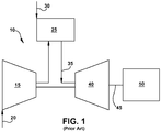
- FIG. 1 shows a schematic view of an illustrative industrial machine in the form of a gas turbine system 10. While the disclosure will be described relative to gas turbine system 10, it is emphasized that the teachings of the disclosure are applicable to any industrial machine having a hot gas path component requiring cooling.
- Gas turbine system 10 may include a compressor 15. Compressor 15 compresses an incoming flow of air 20, and delivers the compressed flow of air 20 to a combustor 25. Combustor 25 mixes the compressed flow of air 20 with a pressurized flow of fuel 30 and ignites the mixture to create a flow of combustion gases 35.
- gas turbine system 10 may include any number of combustors 25.
- Flow of combustion gases 35 is in turn delivered to a turbine 40.
- Flow of combustion gases 35 drives turbine 40 so as to produce mechanical work.
- the mechanical work produced in turbine 40 drives compressor 15 via a shaft 45 and an external load 50 such as an electrical generator and the like.
- Gas turbine system 10 may use natural gas, liquid fuels, various types of syngas, and/or other types of fuels and blends thereof.
- Gas turbine system 10 may be any one of a number of different gas turbine engines offered by General Electric Company of Schenectady, N.Y. and the like. Gas turbine system 10 may have different configurations and may use other types of components. Teachings of the disclosure may be applicable to other types of gas turbine systems and or industrial machines using a hot gas path. Multiple gas turbine systems, or types of turbines, and or types of power generation equipment also may be used herein together.
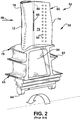
- FIG. 2 shows an example of a hot gas path (HGP) component 52 in the form of a turbine blade 55 that may be used in a hot gas path (HGP) 56 of turbine 40 and the like. While the disclosure will be described relative to HGP component 52 in the form of turbine blade 55 and more specifically an airfoil 60 or wall thereof, it is emphasized that the teachings of the disclosure are applicable to any HGP component requiring cooling.
- turbine blade 55 may include airfoil 60, a shank portion 65, and a platform 70 disposed between airfoil 60 and shank portion 65. Airfoil 60 generally extends radially upward from platform 70 and includes a leading edge 72 and a trailing edge 74.
- Airfoil 60 also may include a concave surface defining a pressure side 76 and an opposite convex surface defining a suction side 78.
- Platform 70 maybe substantially horizontal and planar.
- Shank portion 65 may extend radially downward from platform 70 such that platform 70 generally defines an interface between airfoil 60 and shank portion 65.
- Shank portion 65 may include a shank cavity 80.
- Shank portion 65 also may include one or more angel wings 82 and a root structure 84 such as a dovetail and the like. Root structure 84 may be configured to secure, with other structure, turbine blade 55 to shaft 45 ( FIG. 1 ). Any number of turbine blades 55 may be circumferentially arranged about shaft 45.
- Other components and or configurations also may be used herein.
- Turbine blade 55 may include one or more cooling circuits 86 extending therethrough for flowing a cooling medium 88 such as air from compressor 15 ( FIG. 1 ) or from another source. Steam and other types of cooling mediums 88 also maybe used herein. Cooling circuits 86 and cooling medium 88 may circulate at least through portions of airfoil 60, shank portion 65, and platform 70 in any order, direction, or route. Many different types of cooling circuits and cooling mediums may be used herein in any orientation. Cooling circuits 86 may lead to a number of cooling holes 90 or other types of cooling pathways for film cooling about airfoil 60 or elsewhere. Other types of cooling methods may be used. Other components and or configurations also may be used herein.
- a cooling medium 88 such as air from compressor 15 ( FIG. 1 ) or from another source. Steam and other types of cooling mediums 88 also maybe used herein. Cooling circuits 86 and cooling medium 88 may circulate at least through portions of airfoil 60, shank portion 65, and platform 70 in any order
- FIGS. 3-8 show an example of a portion of an HGP component 100 as maybe described herein.
- FIG. 3 is a perspective view of HGP component 100 without a thermal barrier coating (TBC) thereon
- FIG. 4 is a perspective view of HGP component 100 with a TBC 102 thereon
- FIGS. 5-8 are cross-sectional views of a portion of HGP component without TBC 102.
- HGP component 100 may be an airfoil 110 and more particularly a sidewall thereof.
- HGP component 100 may be a part of a blade or a vane and the like.
- HGP component 100 also may be any type of air-cooled component including a shank, a platform, or any other type of hot gas path component of a blade or vane.
- airfoil 110 may include a leading edge 120 and a trailing edge 130.
- airfoil 110 may include a pressure side 140 and a suction side 150.
- Airfoil 110 also may include one or more internal cooling circuits 160 ( FIGS. 3 and 5 ) therein. As shown in phantom in FIG. 3 and shown in cross-section in FIGS. 5 and 7 , internal cooling circuits 160 may lead to a number of open cooling pathways 170 such as a number of cooling holes 175. A variety of internal cooling circuits 160 may be employed, not all of which are shown. Cooling holes 175 may extend through an outer surface 180 of airfoil 110 or elsewhere. Outer surface 180 is exposed to a working fluid having a high temperature in HGP 56. As used herein, "high temperature” depends on the form of industrial machine, e.g., for gas turbine system 10, high temperature may be any temperature greater than 100°C.
- Cooling holes 175 serve to cool airfoil 110 and components thereof with a cooling medium 190 ( FIG. 5 ) therein.
- Any type of cooling medium 190 such as air, steam, and the like, may be used herein from any source. While one common source of cooling medium 190 is shown, one or more sources may be employed.
- Cooling holes 175 may have any size, shape, or configuration. Any number of cooling holes 175 may be used herein. Cooling holes 175 may extend to outer surface 180 in an orthogonal or non-orthogonal manner. Other types of open cooling pathways 170 may be used herein. Other components and or configurations may be used herein.
- HGP component 100 e.g., airfoil 110
- HGP component 100 also may include a number of other adaptively opening cooling pathways 200 including: a primary cooling pathway 202 and a backup, secondary cooling pathway 204 (hereinafter "secondary cooling pathway 204") according to embodiments of the disclosure.
- secondary cooling pathway 204 may, in certain embodiments, include a plurality of interconnected secondary cooling pathways 204, i.e., they are fluidly communicative with one another.
- primary cooling pathway 202 may include a plurality of primary cooling pathways 202 that may or may not be interconnected.
- HGP component 100 may include a body 112, e.g., sidewall of airfoil 110, including outer surface 180.
- Cooling pathways 200 may have any size, shape (e.g., circular, round, polygonal, etc.), or configuration. In one embodiment, cooling pathways 200 may have a dimension of approximately 0.25 millimeters (mm) to 2.5 mm, and nominally, approximately 0.76 mm to 1.52 mm. In one embodiment, primary and secondary cooling pathways 202, 204 may have different sizes, e.g., secondary cooling pathway 204 may be smaller than primary cooling pathway 202. (See e.g., FIGS. 6 and 8 ) In one embodiment, cooling pathways 200 have a circular cross-section.
- cooling pathways 200 are positioned internally from outer surface 180.
- Primary cooling pathway 202 may extend along and may be spaced internally from outer surface 180 in a substantially consistent manner such that primary cooling pathway 202 extends parallel along and internally from outer surface 102, e.g., within +/-1-3° variance.
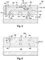
- FIG. 5 and 6 show primary cooling pathway 202 and secondary cooling pathway 204 aligned relative to outer surface 180 (i.e., over one another as viewed perpendicularly from outer surface 180), while FIGS. 7 and 8 shows primary cooling pathway 202 and secondary cooling pathway 204 laterally offset relative to one another (i.e., into and out of page in FIG. 7 ) so they are not aligned relative to outer surface 180.
- primary cooling pathway 202 is shown in phantom in FIG. 7 .
- FIG. 6 shows the same portion of HGP component 100 from FIG. 5 in a lateral cross-section (perpendicular to longitudinal cross-section of FIG. 5 ).
- primary cooling pathway 202 may be parallel with secondary cooling pathway 204. Further, primary cooling pathway 202 is aligned with secondary cooling pathway 204 relative to outer surface 180, i.e., directly over one another as viewed perpendicular to outer surface 180. In contrast, as shown in FIG. 8 , primary cooling pathway 202 and secondary cooling pathway 204 may be parallel with each other but laterally offset from one another. That is, they may be not be over one another along their lengths 212 relative to outer surface 180, i.e., they are not directly over one another as viewed perpendicular to outer surface 180.
- primary cooling pathway 202 may be positioned internally at a first spacing D1 from outer surface 180
- secondary cooling pathway 204 may be positioned internally at a secondary spacing D2 from outer surface 180.
- second spacing D2 may be approximately 0.25 mm to 3.56 mm, and nominally, approximately 0.51 mm to 1.52 mm
- first spacing D1 may be approximately 0.12 mm to 1.27 mm, and nominally, approximately 1.02 mm.
- first spacing D1 is less than second spacing D2.
- first spacing D1 and second spacing D2 are substantially consistent along lengths 212 such that cooling pathways 200 extends parallel along and internally from outer surface 180.
- first and second spacing D1, D2 may be possible to accommodate structural variations such as but not limited to: a varied shape of outer surface 180, surface roughness of outer surface 180, variation of cooling pathways 200 as they progress through body 112, other internal structure that must be routed around, etc.
- First spacing D1 can vary so long as it is sufficiently thin to allow for opening of body 112 to outer surface 180 at a location when necessary, as will be described herein.
- second spacing D2, and more particularly, a third spacing D3 between primary cooling pathway 202 and secondary cooling pathway 204 can vary.
- second spacing D2 can be sized sufficiently thin to allow for opening of body 112 from secondary cooling pathway 204 to outer surface 180 when necessary.
- third spacing D3 can be sized sufficiently thin to allow for opening of body 112 at a location within primary cooling pathway 202 when necessary, i.e., from primary cooling pathway 202 to secondary cooling pathway 204.
- third spacing D3 may be approximately 0.13 mm to 1.54 mm, and nominally, approximately 0.51 mm.
- primary cooling pathway 202 extend towards outer surface 180 and is open to outer surface 180 (including any TBC) at an open end 210 in a manner similar to cooling holes 175.
- primary cooling pathway 202 need not exit through outer surface 180 in all instances, i.e., it could simply supply another cooling pathway.
- each second cooling pathway 204 may connect at both ends 211, 213 to internal cooling circuit 160.
- only one end 211 or 213 may be coupled to internal cooling circuit 160, and the other end may terminate at a terminating end 215 (see e.g., FIGS. 11 and 18 ) in body 112.
- Secondary cooling pathways 204 are not open through outer surface 180, when constructed.
- secondary cooling pathways 204 are distinguishable from open cooling pathways 170 and cooling holes 175 that are permanently open to outer surface 180. Lengths 212 of either pathway 202, 204 can be any distance desired. As will be described herein, any number of cooling pathways 200 may be used herein, and they can extend in any direction and have any orientation within HGP component 100. In any event, cooling medium 190 does not flow through secondary cooling pathway 204 until an overheating event creates a first opening 230 to allowing flow therethrough. Consequently, as will be described further herein, a primary flow 192 (e.g., FIG. 5 ) of cooling medium 190 may flow in primary cooling pathway 202 prior to an overheating event, but a secondary flow 194 (e.g., FIGS. 13-20 ) of cooling medium 190 may not flow in secondary cooling pathway 204 until after an overheating event.
- a primary flow 192 e.g., FIG. 5
- secondary flow 194 e.g., FIGS. 13-20
- each cooling pathway 200 may include a length 212 extending along and spaced internally from outer surface 180.
- An additional connecting cooling pathway 214 may also fluidly couple cooling pathways 200, i.e., lengths 212, to internal cooling circuit(s) 160, but this segment may not be necessary depending on the location of internal cooling circuit(s) 160. (although internal cooling circuit 160 is labeled as one circuit or pathway herein, it is understood that it may include any number of cooling medium circuits or pathways).
- FIGS. 5-8 show just a couple of embodiments of how primary and secondary cooling pathways 202, 204 can be arranged for initial description purposes. Practically any arrangement in which secondary cooling pathways 204 can open to outer surface 180 and/or primary cooling pathways 202 are possible. In the latter case, primary cooling pathway 202 and secondary cooling pathway 204 can overlap so that secondary cooling pathway 204 can open to primary cooling pathway 202 alone, or to primary cooling pathway 202 and outer surface. Practically any arrangement in which pathways 202, 204 overlap such that an opening from secondary cooling pathway 204 can open to outer surface 180 and/or primary cooling pathway 202 is within the scope of the disclosure.
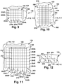
- FIGS. 9-12 show schematic plan views of various arrangements of primary cooling pathway 202 relative to secondary cooling pathways 204. It is emphasized that the examples shown are not comprehensive and that a large variety of alternatives may be possible.
- primary cooling pathways 202 are shown with solid lines and secondary cooling pathways 204 are shown with dashed lines.
- Potential locations for internal cooling circuit 160 to cooling pathways 200 are shown with circles or ovals, and terminating ends 215 ( FIG. 11 ) are shown with dots. Any number of internal cooling circuits 160 may couple to cooling pathways 200, e.g., one for both, one for each, more than one for each, etc.
- secondary cooling pathway(s) 204 is spaced internally from primary cooling pathway 202, as in FIGS. 5-8 .
- FIG. 9 shows an embodiment in which secondary cooling pathway 204 includes a plurality of secondary cooling pathways 204A-D and the primary cooling pathway 202 includes a plurality of primary cooling pathways 202A-D.
- Each of the pluralities may include any number of pathways.
- plurality of secondary cooling pathways 204 are spaced internally from plurality of primary cooling pathways 202, as in FIGS. 5-8 .
- secondary cooling pathway 204 does not parallel primary cooling pathway 202. Rather, they cross under/over one another.
- FIG. 10 shows an embodiment in which each cooling pathway 202, 204 are laid out in a sinusoidal pattern, but in a perpendicular manner to one another.
- FIG. 11 shows an embodiment in which a plurality of interconnected secondary cooling pathways 204A-K and a plurality of primary cooling pathways 202A-E are provided. Interconnected secondary cooling pathways 202A-K are spaced internally from plurality of primary cooling pathways 202A-E and can feed secondary flow 194 of cooling medium 190 to at least one of the outer surface 180 and at least one of plurality of primary cooling pathways 202A-E.
- plurality of secondary cooling pathways 204 are arranged in a net shape internally of plurality of primary cooling pathways 202.
- secondary cooling pathways 204 include a set of pathways 204A-G that extend in a first direction (e.g., up/down page) and another set of pathways 204H-K that extend in a perpendicular second direction (e.g., across page).
- set of secondary cooling pathways 204A-K are fluidly interconnected at their junctions 232 such that the same secondary flow 194 is in all of them and such that if one opens, they all feed to that opening.
- all of the secondary cooling pathways 204A-K are shown fluidly coupled to a respective internal cooling circuit 160, only one of them need be so connected.
- secondary cooling pathways 204A-K do not join together at junctions 232 but are all separately coupled to an internal cooling circuit 160.
- secondary cooling pathways 204 cross primary cooling pathways 202, i.e., secondary cooling pathways 204 pass under but are not fluidly communicative with and do not intersect primary pathways 202.
- certain secondary cooling pathway(s) e.g., 204H-K, are laterally offset from and parallel primary cooling pathway(s) 204.
- a first opening 230 to occur from outer surface 180 directly to secondary cooling pathway 204 where a temperature exceeds the predetermined temperature of body 112, bypassing primary cooling pathway 202. While a net shape has been illustrated in FIG.
- pathways 200 can have any two dimensional or three dimensional arrangement necessary to provide the desired cooling, e.g., webbed, rounded, helical, etc. While arrangements are shown with plural cooling pathways 202, 204, as shown in one example in FIG. 11 , any of the arrangements can be implemented using one or more primary cooling pathways 202 and/or one or more secondary cooling pathways 204. Further, cooling pathways 202, 204 need not meet at perpendicular angles, and need not be linear. In arrangements where a number of cooling pathways 202, 204 are used, spacing between adjacent pathways need not be equal.
- FIG. 12 shows an embodiment in which a secondary cooling pathway 204 crosses (under) aprimary cooling pathway 202 at a non-perpendicular angle. That is, secondary cooling pathway(s) 204 does not parallel (nor is perpendicular) to primary cooling pathway(s) 202.
- FIG. 12 also shows an embodiment including a single primary cooling pathway 202 over a plurality of secondary cooling pathways 204. As noted, the teachings of the disclosure can be applied where there is a plurality of both cooling pathways 202, 204, or just a plurality of one of them and a single version of the other. Cooling pathways 200, i.e., at least portions of outer surface 180, may optionally include a thermal barrier coating (TBC) 102 thereover.
- TBC thermal barrier coating
- FIGS. 4 , 19 and 20 show embodiments that include TBC 102.
- TBC 102 is positioned over outer surface 180 in at least a portion of HGP component 100 to cover cooling pathways 200. Open ends 210 of primary cooling pathway 202, when provided, may extend through TBC 102.
- TBC 102 extends over outer surface 180, and is exposed to HGP 56 including a working fluid having a high temperature, as previously noted.
- TBC 102 may include any now known or later developed layers of materials configured to protect outer surface 180 from thermal damage (e.g., creep, thermal fatigue cracking and/or oxidation) such as but not limited to: zirconia, yttria-stabilized zirconia, a noble metal-aluminide such as platinum aluminide, MCrAlY alloy in which M may be cobalt, nickel or cobalt-nickel alloy.
- TBC 102 may include multiple layers such as but not limited to a bond coat under a thermal barrier layer.
- secondary cooling pathway 204 opens at first opening 230 to the primary cooling pathway 202 to allow a secondary flow 194 of cooling medium 190 through from secondary cooling pathway 204.
- Secondary flow 194 acts to cool the overheating area and possibly downstream areas, e.g., in or around outer surface 180 and/or primary cooling pathway 202.
- a location 224 e.g., FIG. 13 ) at which an opening occurs may be at, near or distanced from the cause of an overheating event and may be anywhere along lengths 212 of cooling pathways 200. In this fashion, even though the exact positioning of on overheating event cannot be accurately predicted, secondary cooling pathway 204 can provide adequate cooling over length 212.
- location 224 can be at any location about primary cooling pathway 202, e.g., above, below, within, to the side, etc.
- an “overheating event” may take a number of forms according to embodiments of the disclosure.
- the overheating event may include a temperature at a location reaching or exceeding a predetermined temperature of body 112, causing an opening(s) to form from secondary cooling pathway 204 to provide a secondary flow 194 of cooling medium 190, e.g., to primary cooling pathway 202 and/or outer surface 180.
- an opening may form from secondary cooling pathway 204 at, near or distant from the location of the overheating event.
- the "predetermined temperature of body 112" is a temperature at which body 112 will change state in such a way as to allow its removal to create an opening, e.g., through sublimation, ashing, cracking, or melting thereof. That is, the high temperature causes a deterioration, or removal of a portion of body 112 at, near or distant from the overheating event, creating an opening, e.g., first opening 230 from secondary cooling pathway 204 allowing a secondary flow 194 of cooling medium 190 therethrough.
- the overheating event may have a variety of different causes such as but not limited to an at least partial blockage of a cooling pathway, a reduced cooling medium flow in a cooling pathway for reasons other than a blockage, or simply an unanticipated overheating area.
- an amount of overheating can determine a size of opening(s), which automatically provides increased cooling for higher temperatures and less cooling for lower temperatures.
- FIGS. 13-20 describe a variety of illustrative overheating events and ways in which secondary cooling pathway 204 may operate to provide adaptive, backup cooling.
- an overheating event is illustrated as an at least partial blockage 223 of primary cooling pathway 202, e.g., by a collapse, clog or other failure, causing an at least reduced primary flow 192' of cooling medium 190.
- FIGS. 13-15 show this form of overheating event relative to the FIGS. 5 and 6 embodiments (with aligned pathways 202, 204); it is emphasized however that teachings of FIGS. 13-15 are equally applicable to the FIGS. 7 and 8 embodiments (laterally offset pathways 202, 204).
- the overheating event includes a temperature in primary cooling pathway 202 reaching or exceeding the predetermined temperature of body 112 causing secondary cooling pathway 204 to open at first opening 230 (at or near blockage 223) to primary cooling pathway 202, allowing secondary flow 194 of cooling medium 190 through to at least primary cooling pathway 202.
- FIG. 13 shows one example in which the overheating event creates only a first opening 230 (downstream of blockage 223) from secondary cooling pathway 204 to primary cooling pathway 202, allowing a secondary flow 194 of cooling medium 190 to provide cooling to primary cooling pathway 202 downstream of the at least partial blockage 223.
- FIG. 14 shows another example, similar to FIG.
- the overheating event includes a temperature of outer surface 180 over primary cooling pathway 202 reaching or exceeding a predetermined temperature of body 112 causing primary cooling pathway 202 to open at second opening 231 to outer surface 180, and a temperature in the open primary cooling pathway 202 reaching or exceeding the predetermined temperature of body 112 causing secondary cooling pathway 204 to open at first opening 230 to primary cooling pathway 202, allowing secondary flow 194 of cooling medium through to 180 outer surface and primary cooling pathway 202.
- third spacing D3 i.e., inner wall of primary cooling pathway 202
- secondary cooling pathway 204 may open at first opening 230 in open primary cooling pathway 202 to allow secondary flow 194 of cooling medium 190 therethrough to provide additional cooling. That is, the continuing high temperature of HGP 56 causes a deterioration, or removal of third spacing D3, creating first opening 230 to secondary cooling pathway 204 allowing a secondary flow 194 of cooling medium 190 therethrough.
- an amount of overheating can determine a size of first opening 230 to secondary cooling pathway 204, which automatically provides increased cooling for higher temperatures and less cooling for lower temperatures.
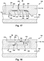
- first opening 230 may occur alone, i.e., the overheating event in the form of at least partial blockage 223 includes a temperature of outer surface 180 over primary cooling pathway 202 reaching or exceeding a predetermined temperature of body 112 causing second cooling pathway 204 to open directly to outer surface 180 (see e.g., FIGS. 17 and 19 ). This latter example is more likely to occur relative to the laterally offset configurations of FIG. 7 and 8 .
- the overheating event also includes at least partial blockage 223, but openings 230, 231 occur upstream of the at least partial blockage 223.
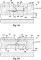
- the locations of second opening 231 maybe over first opening 230, i.e., that is the locations of openings 230, 231 are aligned relative to outer surface 180. That may not be the case in all instances, e.g., see FIG. 18 .
- the overheating event may also simply include an unexpected hot spot 227. That is, a location of the overheating event is an area that does not appear to have any damage, but has a high temperature exceeding the predetermined temperature of body 112. Unexpected hot spot 227 may be, for example, the result of primary cooling pathway 202 or surrounding structure not having been designed to accommodate a higher than expected temperature. While FIG. 16 has been shown only creating first opening 230 from secondary cooling pathway 204 to primary cooling pathway 202, it is understood that second opening 231 from primary cooling pathway 202 to outer surface 180, as in FIGS. 14 and 15 , could also be formed with this type of overheating event. Indeed, either of the FIGS. 14-15 embodiments are possible with an overheating event as described relative to FIG. 16 .
- FIG. 17 shows an example outside of the scope of the claims in which primary and secondary cooling pathways 202, 204 are not aligned. While shown as perpendicular to one another, like in FIGS. 9 or 10 , cooling pathways 202, 204 could also be laterally offset (like secondary cooling pathways 204H-K relative to primary cooling pathways 202A-E in FIG. 11 ) or are otherwise not aligned (like in any of FIGS. 9-12 ).
- overheating event includes a temperature of outer surface 180 over secondary cooling pathway 204 reaching or exceeding a predetermined temperature of body 112 causing secondary cooling pathway 204 to open at first opening 230 to outer surface 180, directing at least a portion of secondary flow 194 of cooling medium 190 therethrough. That is, secondary cooling pathway 204 opens directly to outer surface 180 through second spacing D2. In this fashion, overheating events that occur at locations where primary cooling pathways 202 are not present can still be adaptively cooled using secondary flow 194 of cooling medium 190.
- first opening 230 and second opening 231 may be aligned relative to outer surface 180 and relative to one another. It is emphasized however that opening 230, 231 alignment may not occur in all instances as the locations at which one opening occurs may not cause the other opening to be aligned. As illustrated in FIG. 18 , for example, second opening 231 is not aligned with first opening 230 relative to outer surface 180. For example, first opening 230 maybe downstream of second opening 231 to outer surface 180 because the overheating event includes a sub-event that occurs downstream from where a portion of primary flow 192 is escaping through outer surface 180. ( FIG. 18 also shows a secondary cooling pathway that terminates at a terminating end 215 within body 112). In other examples, as shown best by FIG. 15 , first and second openings 230, 231 may be offset from each other relative to the plane of the page, or angularly offset from one another relative to primary cooling pathway 202.
- FIGS. 19 and 20 show examples including TBC 102 over outer surface 180. That is, TBC 102 is over at least a portion of outer surface 180, and TBC 102 is exposed to the working fluid having the high temperature in HGP 56.
- the overheating event may include the temperature of outer surface 180 reaching or exceeding the predetermined temperature of body 112 in response to a spall 222 occurring in TBC 102.
- Spall 222 may include any change in TBC 102 creating a thermal path to outer surface 180 from HGP 56 not previously present, e.g., a break or crack in, or displacement. In one embodiment, spall 222 may have a dimension of approximately 6 mm diameter.
- FIGS. 19-20 show a couple of examples of overheating events with a TBC 102 that are similar to those of FIGS. 17 and 14 , respectively.
- FIG. 19 which shows an example that does not fall under the scope of the claims, in response to spall 222 in TBC 102 occurring over secondary cooling pathway 204 and the temperature reaching or exceeding a predetermined temperature of body 112, secondary cooling pathway 204 opens at first opening 230 directly to outer surface 180 to allow secondary flow 194 of cooling medium 190 therethrough.
- first opening 230 may be anywhere along length 212 of secondary cooling pathway 204. In this fashion, even though the exact positioning of spall 222 cannot be accurately predicted, cooling pathway 200 can provide adequate cooling over length 212. In addition, an extent of spall 222 determines a size of first opening 230 in secondary cooling pathway 204, which automatically provides increased cooling for larger spalls 222 (larger opening) and less cooling for smaller spalls 222 (smaller openings 230).
- primary cooling pathway 202 may open at second opening 231.
- secondary cooling pathway 204 may open at first opening 230 to primary cooling pathway 202 to allow secondary flow 194 of cooling medium therethrough.
- first and second openings 230, 231 are aligned relative to outer surface 180, but as noted herein they may not be aligned. In one example, as shown in FIG.
- first opening 230 may occur alone, i.e., the overheating event in the form of spall 22 may include a temperature of outer surface 180 over primary cooling pathway 202 reaching or exceeding a predetermined temperature of body 112 causing second cooling pathway 204 to open directly to outer surface 180.
- This latter embodiment is more likely to occur relative to the laterally offset configurations of FIG. 7 and 8 .
- an amount of overheating can determine a size of opening(s) 230, 231, which automatically provides increased cooling for higher temperatures and less cooling for lower temperatures. While singular first openings 230 and singular second openings 231 have been illustrated, it is understood that each may include more than one opening of its type where the overheating event dictates. Further, while different overheating events have been described separately herein, it is understood that an overheating event may include one or more of the types of events described herein. While FIGS. 13-18 have been described with no TBC 102 and FIGS. 19-20 have been described relative to a TBC 102, it is recognized that the various embodiments may be applied whether a TBC is present or not. Further, the different embodiments of HGP component 100 are not mutually exclusive to the particular examples as shown in the drawings. Features described herein can be taken from other embodiments and combined where necessary in a manner other than that explicitly described.
- HGP component 100 and cooling pathways 200 may be constructed entirely using conventional techniques, e.g., casting, machining, etc. Referring to FIG. 21 , in accordance with embodiments of the disclosure, HGP component 100 and cooling pathways 200 may be additively manufactured. Additive manufacturing also allows for easy formation of much of the structure described herein, i.e., without very complex machining. As used herein, additive manufacturing (AM) may include any process of producing an object through the successive layering of material rather than the removal of material, which is the case with conventional processes. Additive manufacturing can create complex geometries without the use of any sort of tools, molds or fixtures, and with little or no waste material.
- additive manufacturing additive manufacturing
- Additive manufacturing processes may include but are not limited to: 3D printing, rapid prototyping (RP), direct digital manufacturing (DDM), binder jetting, selective laser melting (SLM) and direct metal laser melting (DMLM).
- RP rapid prototyping
- DDM direct digital manufacturing
- SLM selective laser melting
- DMLM direct metal laser melting
- FIG. 21 shows a schematic/block view of an illustrative computerized additive manufacturing system 500 for generating an object 502, i.e., HGP component 100.
- system 500 is arranged for DMLM.
- AM system 500 generally includes a computerized additive manufacturing (AM) control system 504 and an AM printer 506.
- AM system 500 executes code 520 that includes a set of computer-executable instructions defining HGP component 100 ( FIGS. 5-20 ) and cooling pathways 200, to physically generate the component using AM printer 506.
- Each AM process may use different raw materials in the form of, for example, fine-grain powder, liquid (e.g., polymers), sheet, etc., a stock of which may be held in a chamber 510 of AM printer 506.
- HGP component 100 FIGS. 5-20
- an applicator 512 may create a thin layer of raw material 514 spread out as the blank canvas from which each successive slice of the final object will be created.
- applicator 512 may directly apply or print the next layer onto a previous layer as defined by code 520, e.g., where the material is a polymer or where a metal binder jetting process is used.
- a laser or electron beam 516 fuses particles for each slice, as defined by code 520, but this may not be necessary where a quick setting liquid plastic/polymer is employed.
- Various parts of AM printer 506 may move to accommodate the addition of each new layer, e.g., a build platform 518 may lower and/or chamber 510 and/or applicator 512 may rise after each layer.
- AM control system 504 is shown implemented on computer 530 as computer program code.
- computer 530 is shown including a memory 532, a processor 534, an input/output (I/O) interface 536, and a bus 538.
- I/O input/output
- computer 530 is shown in communication with an external I/O device 540 and a storage system 542.
- processor 534 executes computer program code, such as AM control system 504, that is stored in memory 532 and/or storage system 542 under instructions from code 520 representative of HGP component 100 ( FIGS. 5-20 ), described herein. While executing computer program code, processor 534 can read and/or write data to/from memory 532, storage system 542, I/O device 540 and/or AM printer 506.
- Bus 538 provides a communication link between each of the components in computer 530, and I/O device 540 can comprise any device that enables a user to interact with computer 530 (e.g., keyboard, pointing device, display, etc.).
- Computer 530 is only representative of various possible combinations of hardware and software.
- processor 534 may comprise a single processing unit, or be distributed across one or more processing units in one or more locations, e.g., on a client and server.
- memory 532 and/or storage system 542 may reside at one or more physical locations.
- Memory 532 and/or storage system 542 can comprise any combination of various types of non-transitory computer readable storage medium including magnetic media, optical media, random access memory (RAM), read only memory (ROM), etc.
- Computer 530 can comprise any type of computing device such as a network server, a desktop computer, a laptop, a handheld device, a mobile phone, a pager, a personal data assistant, etc.
- Additive manufacturing processes begin with a non-transitory computer readable storage medium (e.g., memory 532, storage system 542, etc.) storing code 520 representative of HGP component 100 ( FIGS. 5-20 ).
- code 520 includes a set of computer-executable instructions defining object 502 that can be used to physically generate the object, upon execution of the code by system 500.
- code 520 may include a precisely defined 3D model of HGP component 100 ( FIGS. 5-20 ) and can be generated from any of a large variety of well-known computer aided design (CAD) software systems such as AutoCAD®, TurboCAD®, DesignCAD 3D Max, etc.
- CAD computer aided design
- code 520 can take any now known or later developed file format.
- code 520 may be in the Standard Tessellation Language (STL) which was created for stereolithography CAD programs of 3D Systems, or an additive manufacturing file (AMF), which is an American Society of Mechanical Engineers (ASME) standard that is an extensible markup-language (XML) based format designed to allow any CAD software to describe the shape and composition of any three-dimensional object to be fabricated on any AM printer.
- STL Standard Tessellation Language
- AMF additive manufacturing file
- ASME American Society of Mechanical Engineers
- XML extensible markup-language
- Code 520 may be translated between different formats, converted into a set of data signals and transmitted, received as a set of data signals and converted to code, stored, etc., as necessary.
- Code 520 may be an input to system 500 and may come from a part designer, an intellectual property (IP) provider, a design company, the operator or owner of system 500, or from other sources.
- IP intellectual property
- AM control system 504 executes code 520, dividing HGP component 100 ( FIGS. 5-20 ) into a series of thin slices that it assembles using AM printer 506 in successive layers of liquid, powder, sheet or other material. In the DMLM example, each layer is melted to the exact geometry defined by code 520 and fused to the preceding layer.
- HGP component 100 ( FIGS. 5-20 ) may be exposed to any variety of finishing processes, e.g., minor machining, sealing, polishing, assembly to another part, etc.
- TBC 102 may be optionally applied to outer surface 180 of HGP component 100 and over cooling pathways 200.
- TBC 102 may be applied using any now known or later developed coating techniques, and may be applied in any number of layers.
- HGP component 100 provides cooling pathways 200 that only open in a location where unanticipated overheating above a predetermined temperature of body 112 is observed.
- the use of primary cooling pathway 202 backed up by secondary cooling pathway 202, where necessary, allows for cooling of overheating locations in an adaptive, autonomous manner and prevents overheating event to the underlying metal, which may significantly reduce nominal cooling flows.
- secondary cooling pathway 204 is offset from primary cooling pathway 202, so it may alone provide cooling of overheating locations in an adaptive, autonomous manner and prevent damage to the underlying metal, which may significantly reduce nominal cooling flows.
- the temperatures reached, the size of spall 222 and/or previously formed openings may dictate the size of the opening(s) created, and hence the amount of cooling.
- Approximating language may be applied to modify any quantitative representation that could permissibly vary without resulting in a change in the basic function to which it is related. Accordingly, a value modified by a term or terms, such as “about,” “approximately” and “substantially,” are not to be limited to the precise value specified. In at least some instances, the approximating language may correspond to the precision of an instrument for measuring the value.
- range limitations may be combined and/or interchanged, such ranges are identified and include all the sub-ranges contained therein unless context or language indicates otherwise. "Approximately” as applied to a particular value of a range applies to both values, and unless otherwise dependent on the precision of the instrument measuring the value, may indicate +/- 10% of the stated value(s).
Landscapes
- Engineering & Computer Science (AREA)
- Mechanical Engineering (AREA)
- General Engineering & Computer Science (AREA)
- Chemical & Material Sciences (AREA)
- Combustion & Propulsion (AREA)
- Physics & Mathematics (AREA)
- Fluid Mechanics (AREA)
- Turbine Rotor Nozzle Sealing (AREA)
Claims (12)
- Composant pour utilisation dans un trajet de gaz chaud (56) d'un moteur à turbine à gaz, le composant comprenant :un corps (112) incluant une surface externe (180) qui est exposée, en cours d'utilisation, à un fluide de travail ayant une température élevée dans le trajet de gaz chaud (56) ;un circuit de refroidissement interne (86, 160) dans le corps (112) transportant un milieu de refroidissement (88, 190) ;une voie de refroidissement primaire (202) espacée de façon interne par rapport à la surface externe (180) dans le corps (112) et en communication fluidique avec le circuit de refroidissement interne (86, 160), la voie de refroidissement primaire (202), en cours d'utilisation, communiquant fluidiquement un écoulement primaire (192, 192') du milieu de refroidissement (88, 190) à travers celle-ci à partir du circuit de refroidissement interne (86, 160) ; etune voie de refroidissement secondaire (204) dans le corps (112) et en communication fluidique avec le circuit de refroidissement interne (86, 160), la voie de refroidissement secondaire (204) sans communication fluidique et espacée de façon interne par rapport à la voie de refroidissement primaire (202),caractérisé en ce queen réponse à un événement de surchauffe en cours d'utilisation, la voie de refroidissement secondaire (204) s'ouvre au niveau d'une première ouverture (230) vers la voie de refroidissement primaire (202) pour permettre un écoulement secondaire (194) de milieu de refroidissement (88, 190) jusqu'à la voie de refroidissement primaire (202) à partir de la voie de refroidissement secondaire (204),dans lequel, en cours d'utilisation, l'écoulement primaire (192, 192') du milieu de refroidissement (88, 190) s'écoule dans la voie de refroidissement primaire (202) avant l'événement de surchauffe, et l'écoulement secondaire (194) de milieu de refroidissement (88, 190) ne s'écoule pas dans la voie de refroidissement secondaire (204) jusqu'après l'événement de surchauffe ;dans lequel l'événement de surchauffe inclut une température dans la voie de refroidissement primaire (202) amenant, en cours d'utilisation, une partie du corps (112) à atteindre ou dépasser une température prédéterminée, amenant la partie du corps (112) à changer d'état d'une manière telle à permettre son retrait pour définir la première ouverture (230), ce qui permet l'écoulement secondaire (194) de milieu de refroidissement (88, 190) jusqu'à la voie de refroidissement primaire (202).
- Composant selon la revendication 1, dans lequel l'événement de surchauffe inclut la température dans une partie du corps (112) atteignant ou dépassant une température prédéterminée du corps (112), amenant la première ouverture (230) à se former à partir de la voie de refroidissement secondaire (204).
- Composant selon la revendication 1, dans lequel
l'événement de surchauffe inclut une température de la surface externe (180) par-dessus la voie de refroidissement primaire (202) atteignant ou dépassant une température prédéterminée, amenant, en cours d'utilisation, une partie supplémentaire du corps (112) adjacente à la surface externe par-dessus la voie de refroidissement primaire à changer d'état d'une manière telle à permettre son retrait pour amener la voie de refroidissement primaire (202) à s'ouvrir au niveau d'une deuxième ouverture (231) vers la surface externe (180), permettant, en cours d'utilisation, l'écoulement secondaire (194) de milieu de refroidissement (88, 190) jusqu'à la surface externe (180) et la voie de refroidissement primaire (202). - Composant selon la revendication 3, dans lequel l'événement de surchauffe inclut une obstruction au moins partielle (223) de la voie de refroidissement primaire (202) amenant au moins un écoulement primaire réduit (192, 192') du milieu de refroidissement (88, 190).
- Composant selon la revendication 3 ou 4, dans lequel la première ouverture (230) et la deuxième ouverture (231) sont alignées par rapport à la surface externe (180).
- Composant selon l'une quelconque des revendications 3 à 5, comprenant en outre un revêtement barrière thermique (102) par-dessus au moins une partie de la surface externe (180), le revêtement barrière thermique (102) exposé au fluide de travail ayant la température élevée dans le trajet de gaz chaud (56), et
dans lequel l'événement de surchauffe inclut un éclat (22, 222) se produisant dans le revêtement barrière thermique (102). - Composant selon la revendication 6, dans lequel une étendue de l'éclat (22, 222) détermine une taille de la première ouverture (230).
- Composant selon une quelconque revendication précédente, dans lequel la voie de refroidissement secondaire (204) se termine à l'intérieur du corps (112).
- Composant selon une quelconque revendication précédente, dans lequel la voie de refroidissement primaire (202) s'étend le long et est espacée de façon interne de la surface externe (180) d'une manière sensiblement cohérente de telle sorte que la voie de refroidissement primaire (202) s'étend parallèle le long et de façon interne à partir de la surface externe (180).
- Composant selon une quelconque revendication précédente, dans lequel la voie de refroidissement secondaire (204) inclut une pluralité de voies de refroidissement secondaires interconnectées (204) et les voies de refroidissement primaires (202) incluent une pluralité de voies de refroidissement primaires (202), la pluralité de voies de refroidissement secondaires (204) espacées de façon interne de la pluralité de voies de refroidissement primaires (202) et alimentant l'écoulement secondaire (194) de milieu de refroidissement (88, 190) à au moins l'une de la pluralité de voies de refroidissement primaires (202).
- Composant selon la revendication 10, dans lequel la pluralité de voies de refroidissement secondaires (204) sont interconnectées et agencées dans une forme nette à l'intérieur de la pluralité de voies de refroidissement primaires (202).
- Composant selon la revendication 1, dans lequel la voie de refroidissement secondaire (204) n'est pas parallèle à la voie de refroidissement primaire (202).
Applications Claiming Priority (1)
| Application Number | Priority Date | Filing Date | Title |
|---|---|---|---|
| US15/609,598 US10760430B2 (en) | 2017-05-31 | 2017-05-31 | Adaptively opening backup cooling pathway |
Publications (2)
| Publication Number | Publication Date |
|---|---|
| EP3409890A1 EP3409890A1 (fr) | 2018-12-05 |
| EP3409890B1 true EP3409890B1 (fr) | 2021-04-14 |
Family
ID=62244376
Family Applications (1)
| Application Number | Title | Priority Date | Filing Date |
|---|---|---|---|
| EP18173988.9A Active EP3409890B1 (fr) | 2017-05-31 | 2018-05-24 | Composant destiné à être utilisé dans la voie de gaz chaud d'un moteur à turbine à gaz |
Country Status (5)
| Country | Link |
|---|---|
| US (1) | US10760430B2 (fr) |
| EP (1) | EP3409890B1 (fr) |
| JP (1) | JP7199159B2 (fr) |
| KR (1) | KR102589625B1 (fr) |
| CN (1) | CN108979733B (fr) |
Families Citing this family (14)
| Publication number | Priority date | Publication date | Assignee | Title |
|---|---|---|---|---|
| US20180223673A1 (en) * | 2017-02-07 | 2018-08-09 | General Electric Company | Hot gas path component with metering structure including converging-diverging passage portions |
| DE102018205721A1 (de) * | 2018-04-16 | 2019-10-17 | MTU Aero Engines AG | Schaufel für eine Strömungsmaschine sowie Verwendung und Herstellungsverfahren derselben |
| US10767492B2 (en) | 2018-12-18 | 2020-09-08 | General Electric Company | Turbine engine airfoil |
| US11053809B2 (en) | 2019-07-16 | 2021-07-06 | General Electric Company | Turbine engine airfoil |
| US11454133B2 (en) | 2019-10-25 | 2022-09-27 | General Electric Company | Coolant delivery via an independent cooling circuit |
| US11434767B2 (en) * | 2019-10-25 | 2022-09-06 | General Electric Company | Coolant delivery via an independent cooling circuit |
| US11480070B2 (en) * | 2019-10-25 | 2022-10-25 | General Electric Company | Coolant delivery via an independent cooling circuit |
| FR3115559B1 (fr) * | 2020-10-28 | 2024-05-03 | Safran | Aube de turbine avec circuits de refroidissement améliorés |
| CN114867317B (zh) * | 2022-05-30 | 2025-01-28 | 福建万芯科技有限公司 | 集装箱数据中心管理方法、装置、存储介质及电子设备 |
| US12601483B2 (en) | 2023-12-29 | 2026-04-14 | Ge Infrastructure Technology Llc | Additively manufactured combustion liner and axial fuel stage injector |
| US12092061B1 (en) | 2023-12-29 | 2024-09-17 | Ge Infrastructure Technology Llc | Axial fuel stage immersed injectors with internal cooling |
| US12281794B1 (en) | 2023-12-29 | 2025-04-22 | Ge Infrastructure Technology Llc | Combustor body and axial fuel stage immersed injectors additively manufactured with different materials |
| US12203655B1 (en) | 2023-12-29 | 2025-01-21 | Ge Infrastructure Technology Llc | Additively manufactured combustor with adaptive cooling passage |
| US12449128B1 (en) | 2024-11-27 | 2025-10-21 | Ge Vernova Infrastructure Technology Llc | Boss for a fuel injection assembly having cooling circuit and combustor provided therewith |
Family Cites Families (38)
| Publication number | Priority date | Publication date | Assignee | Title |
|---|---|---|---|---|
| US3626568A (en) | 1969-04-23 | 1971-12-14 | Avco Corp | Method for bonding pins into holes in a hollow turbine blade |
| GB1492049A (en) * | 1974-12-07 | 1977-11-16 | Rolls Royce | Combustion equipment for gas turbine engines |
| US4136516A (en) * | 1977-06-03 | 1979-01-30 | General Electric Company | Gas turbine with secondary cooling means |
| DE3615226A1 (de) * | 1986-05-06 | 1987-11-12 | Mtu Muenchen Gmbh | Heissgasueberhitzungsschutzeinrichtung fuer gasturbinentriebwerke |
| GB2259118B (en) | 1991-08-24 | 1995-06-21 | Rolls Royce Plc | Aerofoil cooling |
| JP3651490B2 (ja) * | 1993-12-28 | 2005-05-25 | 株式会社東芝 | タービン冷却翼 |
| US5726348A (en) | 1996-06-25 | 1998-03-10 | United Technologies Corporation | Process for precisely closing off cooling holes of an airfoil |
| DE69911948T2 (de) | 1999-08-09 | 2004-11-04 | Alstom Technology Ltd | Verfahren zum Verschliessen von Kühlungsöffnungen eines Gasturbinebauteils |
| US6454156B1 (en) | 2000-06-23 | 2002-09-24 | Siemens Westinghouse Power Corporation | Method for closing core printout holes in superalloy gas turbine blades |
| US6478537B2 (en) | 2001-02-16 | 2002-11-12 | Siemens Westinghouse Power Corporation | Pre-segmented squealer tip for turbine blades |
| WO2003098008A1 (fr) * | 2002-05-22 | 2003-11-27 | Alstom Technology Ltd | Composant a refroidir et procede de realisation d'un orifice de passage dans un composant a refroidir |
| EP1365039A1 (fr) | 2002-05-24 | 2003-11-26 | ALSTOM (Switzerland) Ltd | Porcédé pour couvrir les orifices de refroidissement d'un composant d'une turbine à gaz |
| US6749396B2 (en) | 2002-06-17 | 2004-06-15 | General Electric Company | Failsafe film cooled wall |
| DE10250779A1 (de) | 2002-10-30 | 2004-05-19 | Alstom (Switzerland) Ltd. | Notkühlsystem für ein hitzebelastetes Bauteil |
| EP1630354B1 (fr) | 2004-08-25 | 2014-06-18 | Rolls-Royce Plc | Aube refroidie de turbine à gaz |
| US7186091B2 (en) | 2004-11-09 | 2007-03-06 | General Electric Company | Methods and apparatus for cooling gas turbine engine components |
| EP1669545A1 (fr) | 2004-12-08 | 2006-06-14 | Siemens Aktiengesellschaft | Système de couches, utilisation et procédé pour la fabrication d'un système multicouche |
| US7241107B2 (en) | 2005-05-19 | 2007-07-10 | Spanks Jr William A | Gas turbine airfoil with adjustable cooling air flow passages |
| JP4931507B2 (ja) | 2005-07-26 | 2012-05-16 | スネクマ | 壁内に形成された冷却流路 |
| GB2429515B (en) | 2005-08-11 | 2008-06-25 | Rolls Royce Plc | Cooling method and apparatus |
| US20090074576A1 (en) * | 2006-04-20 | 2009-03-19 | Florida Turbine Technologies, Inc. | Turbine blade with cooling breakout passages |
| US7695243B2 (en) * | 2006-07-27 | 2010-04-13 | General Electric Company | Dust hole dome blade |
| US7674093B2 (en) * | 2006-12-19 | 2010-03-09 | General Electric Company | Cluster bridged casting core |
| US9587832B2 (en) * | 2008-10-01 | 2017-03-07 | United Technologies Corporation | Structures with adaptive cooling |
| US20100239409A1 (en) | 2009-03-18 | 2010-09-23 | General Electric Company | Method of Using and Reconstructing a Film-Cooling Augmentation Device for a Turbine Airfoil |
| GB0916687D0 (en) | 2009-09-23 | 2009-11-04 | Rolls Royce Plc | An aerofoil structure |
| US20110097188A1 (en) | 2009-10-23 | 2011-04-28 | General Electric Company | Structure and method for improving film cooling using shallow trench with holes oriented along length of trench |
| EP2354453B1 (fr) | 2010-02-02 | 2018-03-28 | Siemens Aktiengesellschaft | Composant de moteur à turbine pour un refroidissement adaptatif |
| US8231128B2 (en) | 2010-04-01 | 2012-07-31 | General Electric Company | Integral seal and sealant packaging |
| US8753083B2 (en) | 2011-01-14 | 2014-06-17 | General Electric Company | Curved cooling passages for a turbine component |
| EP2476776B1 (fr) | 2011-01-18 | 2015-08-12 | Siemens Aktiengesellschaft | Procédé de réglage de la consommation en produit de refroidissement dans des composants refroidis activement |
| US8678754B2 (en) | 2011-01-24 | 2014-03-25 | General Electric Company | Assembly for preventing fluid flow |
| US20130052036A1 (en) | 2011-08-30 | 2013-02-28 | General Electric Company | Pin-fin array |
| US8915713B2 (en) | 2011-09-27 | 2014-12-23 | General Electric Company | Offset counterbore for airfoil cooling hole |
| US20130104517A1 (en) | 2011-10-31 | 2013-05-02 | Victor Hugo Silva Correia | Component and method of fabricating the same |
| US9109454B2 (en) | 2012-03-01 | 2015-08-18 | General Electric Company | Turbine bucket with pressure side cooling |
| US9617859B2 (en) | 2012-10-05 | 2017-04-11 | General Electric Company | Turbine components with passive cooling pathways |
| US9784123B2 (en) | 2014-01-10 | 2017-10-10 | Genearl Electric Company | Turbine components with bi-material adaptive cooling pathways |
-
2017
- 2017-05-31 US US15/609,598 patent/US10760430B2/en active Active
-
2018
- 2018-05-24 EP EP18173988.9A patent/EP3409890B1/fr active Active
- 2018-05-28 JP JP2018101142A patent/JP7199159B2/ja active Active
- 2018-05-30 KR KR1020180062053A patent/KR102589625B1/ko active Active
- 2018-05-31 CN CN201810554271.XA patent/CN108979733B/zh active Active
Non-Patent Citations (1)
| Title |
|---|
| None * |
Also Published As
| Publication number | Publication date |
|---|---|
| US10760430B2 (en) | 2020-09-01 |
| JP7199159B2 (ja) | 2023-01-05 |
| JP2019023460A (ja) | 2019-02-14 |
| CN108979733A (zh) | 2018-12-11 |
| CN108979733B (zh) | 2022-10-14 |
| KR20180131477A (ko) | 2018-12-10 |
| EP3409890A1 (fr) | 2018-12-05 |
| KR102589625B1 (ko) | 2023-10-13 |
| US20180347372A1 (en) | 2018-12-06 |
Similar Documents
| Publication | Publication Date | Title |
|---|---|---|
| EP3409890B1 (fr) | Composant destiné à être utilisé dans la voie de gaz chaud d'un moteur à turbine à gaz | |
| EP3409893B1 (fr) | Couverture adaptative pour voie de refroidissement par fabrication additive | |
| EP3409891B1 (fr) | Composants destinés à être utilisés dans la voie de gaz chaud d'une machine industrielle | |
| EP3409889A1 (fr) | Structure de réseau dans la voie de refroidissement par fabrication additive | |
| US10774656B2 (en) | Turbine airfoil multilayer exterior wall | |
| EP3409894B1 (fr) | Couvercle adaptatif pour voie de refroidissement par fabrication additive | |
| US10995621B2 (en) | Turbine airfoil with multiple walls and internal thermal barrier coating | |
| US10392944B2 (en) | Turbomachine component having impingement heat transfer feature, related turbomachine and storage medium | |
| US20200392853A1 (en) | Hot gas path component with metering structure including converging-diverging passage portions | |
| EP3997311B1 (fr) | Flux de refroidissement activé par oxydation | |
| EP3825523B1 (fr) | Viroles de turbine integrales comprenant des grilles de grenaillage et système de turbine associé |
Legal Events
| Date | Code | Title | Description |
|---|---|---|---|
| PUAI | Public reference made under article 153(3) epc to a published international application that has entered the european phase |
Free format text: ORIGINAL CODE: 0009012 |
|
| STAA | Information on the status of an ep patent application or granted ep patent |
Free format text: STATUS: THE APPLICATION HAS BEEN PUBLISHED |
|
| AK | Designated contracting states |
Kind code of ref document: A1 Designated state(s): AL AT BE BG CH CY CZ DE DK EE ES FI FR GB GR HR HU IE IS IT LI LT LU LV MC MK MT NL NO PL PT RO RS SE SI SK SM TR |
|
| AX | Request for extension of the european patent |
Extension state: BA ME |
|
| STAA | Information on the status of an ep patent application or granted ep patent |
Free format text: STATUS: REQUEST FOR EXAMINATION WAS MADE |
|
| 17P | Request for examination filed |
Effective date: 20190530 |
|
| RBV | Designated contracting states (corrected) |
Designated state(s): AL AT BE BG CH CY CZ DE DK EE ES FI FR GB GR HR HU IE IS IT LI LT LU LV MC MK MT NL NO PL PT RO RS SE SI SK SM TR |
|
| STAA | Information on the status of an ep patent application or granted ep patent |
Free format text: STATUS: EXAMINATION IS IN PROGRESS |
|
| 17Q | First examination report despatched |
Effective date: 20200319 |
|
| GRAP | Despatch of communication of intention to grant a patent |
Free format text: ORIGINAL CODE: EPIDOSNIGR1 |
|
| STAA | Information on the status of an ep patent application or granted ep patent |
Free format text: STATUS: GRANT OF PATENT IS INTENDED |
|
| INTG | Intention to grant announced |
Effective date: 20201123 |
|
| GRAS | Grant fee paid |
Free format text: ORIGINAL CODE: EPIDOSNIGR3 |
|
| GRAA | (expected) grant |
Free format text: ORIGINAL CODE: 0009210 |
|
| STAA | Information on the status of an ep patent application or granted ep patent |
Free format text: STATUS: THE PATENT HAS BEEN GRANTED |
|
| AK | Designated contracting states |
Kind code of ref document: B1 Designated state(s): AL AT BE BG CH CY CZ DE DK EE ES FI FR GB GR HR HU IE IS IT LI LT LU LV MC MK MT NL NO PL PT RO RS SE SI SK SM TR |
|
| REG | Reference to a national code |
Ref country code: GB Ref legal event code: FG4D |
|
| REG | Reference to a national code |
Ref country code: CH Ref legal event code: EP |
|
| REG | Reference to a national code |
Ref country code: DE Ref legal event code: R096 Ref document number: 602018015410 Country of ref document: DE |
|
| REG | Reference to a national code |
Ref country code: IE Ref legal event code: FG4D |
|
| REG | Reference to a national code |
Ref country code: AT Ref legal event code: REF Ref document number: 1382547 Country of ref document: AT Kind code of ref document: T Effective date: 20210515 |
|
| REG | Reference to a national code |
Ref country code: LT Ref legal event code: MG9D |
|
| REG | Reference to a national code |
Ref country code: AT Ref legal event code: MK05 Ref document number: 1382547 Country of ref document: AT Kind code of ref document: T Effective date: 20210414 |
|
| REG | Reference to a national code |
Ref country code: NL Ref legal event code: MP Effective date: 20210414 |
|
| PG25 | Lapsed in a contracting state [announced via postgrant information from national office to epo] |
Ref country code: NL Free format text: LAPSE BECAUSE OF FAILURE TO SUBMIT A TRANSLATION OF THE DESCRIPTION OR TO PAY THE FEE WITHIN THE PRESCRIBED TIME-LIMIT Effective date: 20210414 Ref country code: BG Free format text: LAPSE BECAUSE OF FAILURE TO SUBMIT A TRANSLATION OF THE DESCRIPTION OR TO PAY THE FEE WITHIN THE PRESCRIBED TIME-LIMIT Effective date: 20210714 Ref country code: AT Free format text: LAPSE BECAUSE OF FAILURE TO SUBMIT A TRANSLATION OF THE DESCRIPTION OR TO PAY THE FEE WITHIN THE PRESCRIBED TIME-LIMIT Effective date: 20210414 Ref country code: FI Free format text: LAPSE BECAUSE OF FAILURE TO SUBMIT A TRANSLATION OF THE DESCRIPTION OR TO PAY THE FEE WITHIN THE PRESCRIBED TIME-LIMIT Effective date: 20210414 Ref country code: HR Free format text: LAPSE BECAUSE OF FAILURE TO SUBMIT A TRANSLATION OF THE DESCRIPTION OR TO PAY THE FEE WITHIN THE PRESCRIBED TIME-LIMIT Effective date: 20210414 Ref country code: LT Free format text: LAPSE BECAUSE OF FAILURE TO SUBMIT A TRANSLATION OF THE DESCRIPTION OR TO PAY THE FEE WITHIN THE PRESCRIBED TIME-LIMIT Effective date: 20210414 |
|
| PG25 | Lapsed in a contracting state [announced via postgrant information from national office to epo] |
Ref country code: IS Free format text: LAPSE BECAUSE OF FAILURE TO SUBMIT A TRANSLATION OF THE DESCRIPTION OR TO PAY THE FEE WITHIN THE PRESCRIBED TIME-LIMIT Effective date: 20210814 Ref country code: GR Free format text: LAPSE BECAUSE OF FAILURE TO SUBMIT A TRANSLATION OF THE DESCRIPTION OR TO PAY THE FEE WITHIN THE PRESCRIBED TIME-LIMIT Effective date: 20210715 Ref country code: PT Free format text: LAPSE BECAUSE OF FAILURE TO SUBMIT A TRANSLATION OF THE DESCRIPTION OR TO PAY THE FEE WITHIN THE PRESCRIBED TIME-LIMIT Effective date: 20210816 Ref country code: NO Free format text: LAPSE BECAUSE OF FAILURE TO SUBMIT A TRANSLATION OF THE DESCRIPTION OR TO PAY THE FEE WITHIN THE PRESCRIBED TIME-LIMIT Effective date: 20210714 Ref country code: LV Free format text: LAPSE BECAUSE OF FAILURE TO SUBMIT A TRANSLATION OF THE DESCRIPTION OR TO PAY THE FEE WITHIN THE PRESCRIBED TIME-LIMIT Effective date: 20210414 Ref country code: PL Free format text: LAPSE BECAUSE OF FAILURE TO SUBMIT A TRANSLATION OF THE DESCRIPTION OR TO PAY THE FEE WITHIN THE PRESCRIBED TIME-LIMIT Effective date: 20210414 Ref country code: SE Free format text: LAPSE BECAUSE OF FAILURE TO SUBMIT A TRANSLATION OF THE DESCRIPTION OR TO PAY THE FEE WITHIN THE PRESCRIBED TIME-LIMIT Effective date: 20210414 Ref country code: RS Free format text: LAPSE BECAUSE OF FAILURE TO SUBMIT A TRANSLATION OF THE DESCRIPTION OR TO PAY THE FEE WITHIN THE PRESCRIBED TIME-LIMIT Effective date: 20210414 |
|
| REG | Reference to a national code |
Ref country code: CH Ref legal event code: PL |
|
| REG | Reference to a national code |
Ref country code: DE Ref legal event code: R097 Ref document number: 602018015410 Country of ref document: DE |
|
| PG25 | Lapsed in a contracting state [announced via postgrant information from national office to epo] |
Ref country code: EE Free format text: LAPSE BECAUSE OF FAILURE TO SUBMIT A TRANSLATION OF THE DESCRIPTION OR TO PAY THE FEE WITHIN THE PRESCRIBED TIME-LIMIT Effective date: 20210414 Ref country code: ES Free format text: LAPSE BECAUSE OF FAILURE TO SUBMIT A TRANSLATION OF THE DESCRIPTION OR TO PAY THE FEE WITHIN THE PRESCRIBED TIME-LIMIT Effective date: 20210414 Ref country code: SK Free format text: LAPSE BECAUSE OF FAILURE TO SUBMIT A TRANSLATION OF THE DESCRIPTION OR TO PAY THE FEE WITHIN THE PRESCRIBED TIME-LIMIT Effective date: 20210414 Ref country code: SM Free format text: LAPSE BECAUSE OF FAILURE TO SUBMIT A TRANSLATION OF THE DESCRIPTION OR TO PAY THE FEE WITHIN THE PRESCRIBED TIME-LIMIT Effective date: 20210414 Ref country code: RO Free format text: LAPSE BECAUSE OF FAILURE TO SUBMIT A TRANSLATION OF THE DESCRIPTION OR TO PAY THE FEE WITHIN THE PRESCRIBED TIME-LIMIT Effective date: 20210414 Ref country code: LI Free format text: LAPSE BECAUSE OF NON-PAYMENT OF DUE FEES Effective date: 20210531 Ref country code: MC Free format text: LAPSE BECAUSE OF FAILURE TO SUBMIT A TRANSLATION OF THE DESCRIPTION OR TO PAY THE FEE WITHIN THE PRESCRIBED TIME-LIMIT Effective date: 20210414 Ref country code: LU Free format text: LAPSE BECAUSE OF NON-PAYMENT OF DUE FEES Effective date: 20210524 Ref country code: CH Free format text: LAPSE BECAUSE OF NON-PAYMENT OF DUE FEES Effective date: 20210531 Ref country code: CZ Free format text: LAPSE BECAUSE OF FAILURE TO SUBMIT A TRANSLATION OF THE DESCRIPTION OR TO PAY THE FEE WITHIN THE PRESCRIBED TIME-LIMIT Effective date: 20210414 Ref country code: DK Free format text: LAPSE BECAUSE OF FAILURE TO SUBMIT A TRANSLATION OF THE DESCRIPTION OR TO PAY THE FEE WITHIN THE PRESCRIBED TIME-LIMIT Effective date: 20210414 |
|
| REG | Reference to a national code |
Ref country code: BE Ref legal event code: MM Effective date: 20210531 |
|
| PLBE | No opposition filed within time limit |
Free format text: ORIGINAL CODE: 0009261 |
|
| STAA | Information on the status of an ep patent application or granted ep patent |
Free format text: STATUS: NO OPPOSITION FILED WITHIN TIME LIMIT |
|
| 26N | No opposition filed |
Effective date: 20220117 |
|
| PG25 | Lapsed in a contracting state [announced via postgrant information from national office to epo] |
Ref country code: IE Free format text: LAPSE BECAUSE OF NON-PAYMENT OF DUE FEES Effective date: 20210524 |
|
| PG25 | Lapsed in a contracting state [announced via postgrant information from national office to epo] |
Ref country code: IS Free format text: LAPSE BECAUSE OF FAILURE TO SUBMIT A TRANSLATION OF THE DESCRIPTION OR TO PAY THE FEE WITHIN THE PRESCRIBED TIME-LIMIT Effective date: 20210814 Ref country code: FR Free format text: LAPSE BECAUSE OF NON-PAYMENT OF DUE FEES Effective date: 20210614 Ref country code: AL Free format text: LAPSE BECAUSE OF FAILURE TO SUBMIT A TRANSLATION OF THE DESCRIPTION OR TO PAY THE FEE WITHIN THE PRESCRIBED TIME-LIMIT Effective date: 20210414 |
|
| PG25 | Lapsed in a contracting state [announced via postgrant information from national office to epo] |
Ref country code: BE Free format text: LAPSE BECAUSE OF NON-PAYMENT OF DUE FEES Effective date: 20210531 |
|
| GBPC | Gb: european patent ceased through non-payment of renewal fee |
Effective date: 20220524 |
|
| PG25 | Lapsed in a contracting state [announced via postgrant information from national office to epo] |
Ref country code: GB Free format text: LAPSE BECAUSE OF NON-PAYMENT OF DUE FEES Effective date: 20220524 |
|
| PG25 | Lapsed in a contracting state [announced via postgrant information from national office to epo] |
Ref country code: CY Free format text: LAPSE BECAUSE OF FAILURE TO SUBMIT A TRANSLATION OF THE DESCRIPTION OR TO PAY THE FEE WITHIN THE PRESCRIBED TIME-LIMIT Effective date: 20210414 |
|
| PG25 | Lapsed in a contracting state [announced via postgrant information from national office to epo] |
Ref country code: HU Free format text: LAPSE BECAUSE OF FAILURE TO SUBMIT A TRANSLATION OF THE DESCRIPTION OR TO PAY THE FEE WITHIN THE PRESCRIBED TIME-LIMIT; INVALID AB INITIO Effective date: 20180524 |
|
| REG | Reference to a national code |
Ref country code: DE Ref legal event code: R081 Ref document number: 602018015410 Country of ref document: DE Owner name: GENERAL ELECTRIC TECHNOLOGY GMBH, CH Free format text: FORMER OWNER: GENERAL ELECTRIC COMPANY, SCHENECTADY, NY, US |
|
| PG25 | Lapsed in a contracting state [announced via postgrant information from national office to epo] |
Ref country code: MK Free format text: LAPSE BECAUSE OF FAILURE TO SUBMIT A TRANSLATION OF THE DESCRIPTION OR TO PAY THE FEE WITHIN THE PRESCRIBED TIME-LIMIT Effective date: 20210414 |
|
| PG25 | Lapsed in a contracting state [announced via postgrant information from national office to epo] |
Ref country code: MT Free format text: LAPSE BECAUSE OF FAILURE TO SUBMIT A TRANSLATION OF THE DESCRIPTION OR TO PAY THE FEE WITHIN THE PRESCRIBED TIME-LIMIT Effective date: 20210414 |
|
| PGFP | Annual fee paid to national office [announced via postgrant information from national office to epo] |
Ref country code: DE Payment date: 20250423 Year of fee payment: 8 |
|
| PGFP | Annual fee paid to national office [announced via postgrant information from national office to epo] |
Ref country code: IT Payment date: 20250423 Year of fee payment: 8 |
|
| PG25 | Lapsed in a contracting state [announced via postgrant information from national office to epo] |
Ref country code: TR Free format text: LAPSE BECAUSE OF FAILURE TO SUBMIT A TRANSLATION OF THE DESCRIPTION OR TO PAY THE FEE WITHIN THE PRESCRIBED TIME-LIMIT Effective date: 20210414 |