EP3409941B1 - Windkraftanlage mit um 45° geneigter rotorachse gegenüber der senkrechtachse in form eines baums, der sich in die landschaft einfügt - Google Patents
Windkraftanlage mit um 45° geneigter rotorachse gegenüber der senkrechtachse in form eines baums, der sich in die landschaft einfügt Download PDFInfo
- Publication number
- EP3409941B1 EP3409941B1 EP18020127.9A EP18020127A EP3409941B1 EP 3409941 B1 EP3409941 B1 EP 3409941B1 EP 18020127 A EP18020127 A EP 18020127A EP 3409941 B1 EP3409941 B1 EP 3409941B1
- Authority
- EP
- European Patent Office
- Prior art keywords
- rotor
- axis
- wind
- blades
- vertical
- Prior art date
- Legal status (The legal status is an assumption and is not a legal conclusion. Google has not performed a legal analysis and makes no representation as to the accuracy of the status listed.)
- Active
Links
Images




Classifications
-
- F—MECHANICAL ENGINEERING; LIGHTING; HEATING; WEAPONS; BLASTING
- F03—MACHINES OR ENGINES FOR LIQUIDS; WIND, SPRING, OR WEIGHT MOTORS; PRODUCING MECHANICAL POWER OR A REACTIVE PROPULSIVE THRUST, NOT OTHERWISE PROVIDED FOR
- F03D—WIND MOTORS
- F03D5/00—Other wind motors
-
- F—MECHANICAL ENGINEERING; LIGHTING; HEATING; WEAPONS; BLASTING
- F03—MACHINES OR ENGINES FOR LIQUIDS; WIND, SPRING, OR WEIGHT MOTORS; PRODUCING MECHANICAL POWER OR A REACTIVE PROPULSIVE THRUST, NOT OTHERWISE PROVIDED FOR
- F03D—WIND MOTORS
- F03D7/00—Controlling wind motors
- F03D7/02—Controlling wind motors the wind motors having rotation axis substantially parallel to the air flow entering the rotor
- F03D7/0264—Controlling wind motors the wind motors having rotation axis substantially parallel to the air flow entering the rotor for stopping; controlling in emergency situations
- F03D7/0268—Parking or storm protection
-
- F—MECHANICAL ENGINEERING; LIGHTING; HEATING; WEAPONS; BLASTING
- F05—INDEXING SCHEMES RELATING TO ENGINES OR PUMPS IN VARIOUS SUBCLASSES OF CLASSES F01-F04
- F05B—INDEXING SCHEME RELATING TO WIND, SPRING, WEIGHT, INERTIA OR LIKE MOTORS, TO MACHINES OR ENGINES FOR LIQUIDS COVERED BY SUBCLASSES F03B, F03D AND F03G
- F05B2240/00—Components
- F05B2240/99—Components characterised by colour or colour patterns
-
- Y—GENERAL TAGGING OF NEW TECHNOLOGICAL DEVELOPMENTS; GENERAL TAGGING OF CROSS-SECTIONAL TECHNOLOGIES SPANNING OVER SEVERAL SECTIONS OF THE IPC; TECHNICAL SUBJECTS COVERED BY FORMER USPC CROSS-REFERENCE ART COLLECTIONS [XRACs] AND DIGESTS
- Y02—TECHNOLOGIES OR APPLICATIONS FOR MITIGATION OR ADAPTATION AGAINST CLIMATE CHANGE
- Y02E—REDUCTION OF GREENHOUSE GAS [GHG] EMISSIONS, RELATED TO ENERGY GENERATION, TRANSMISSION OR DISTRIBUTION
- Y02E10/00—Energy generation through renewable energy sources
- Y02E10/70—Wind energy
- Y02E10/728—Onshore wind turbines
-
- Y—GENERAL TAGGING OF NEW TECHNOLOGICAL DEVELOPMENTS; GENERAL TAGGING OF CROSS-SECTIONAL TECHNOLOGIES SPANNING OVER SEVERAL SECTIONS OF THE IPC; TECHNICAL SUBJECTS COVERED BY FORMER USPC CROSS-REFERENCE ART COLLECTIONS [XRACs] AND DIGESTS
- Y02—TECHNOLOGIES OR APPLICATIONS FOR MITIGATION OR ADAPTATION AGAINST CLIMATE CHANGE
- Y02E—REDUCTION OF GREENHOUSE GAS [GHG] EMISSIONS, RELATED TO ENERGY GENERATION, TRANSMISSION OR DISTRIBUTION
- Y02E10/00—Energy generation through renewable energy sources
- Y02E10/70—Wind energy
- Y02E10/74—Wind turbines with rotation axis perpendicular to the wind direction
-
- Y—GENERAL TAGGING OF NEW TECHNOLOGICAL DEVELOPMENTS; GENERAL TAGGING OF CROSS-SECTIONAL TECHNOLOGIES SPANNING OVER SEVERAL SECTIONS OF THE IPC; TECHNICAL SUBJECTS COVERED BY FORMER USPC CROSS-REFERENCE ART COLLECTIONS [XRACs] AND DIGESTS
- Y02—TECHNOLOGIES OR APPLICATIONS FOR MITIGATION OR ADAPTATION AGAINST CLIMATE CHANGE
- Y02E—REDUCTION OF GREENHOUSE GAS [GHG] EMISSIONS, RELATED TO ENERGY GENERATION, TRANSMISSION OR DISTRIBUTION
- Y02E70/00—Other energy conversion or management systems reducing GHG emissions
- Y02E70/30—Systems combining energy storage with energy generation of non-fossil origin
Definitions
- the present invention relates to a wind turbine rotor axis inclined at 45 ° to the vertical, with 4 fixed blades arranged at 90 ° relative to each other about the axis of this rotor, and which resembles a tree to fit into the landscape. It can produce electricity or pump water.
- Two wind turbines whose axes of rotation are oriented at 45 ° with respect to the vertical are known from the documents WO 2008/147327 and US 3187816 .
- Wind turbines that currently exist and are equipped with either concave fixed blades or blades of section identical to the wings of aircraft according to the principle of Darrieus, deliver a relatively low rotor torque, because the blade that moves against the wind direction brakes the system enormously.
- Wind turbines with vertical axis and fixed concave blades have a symmetrical shape seen from the front. The wind rushes into the concave blade and results in overpressure.
- the blade opposite the vertical axis offers its convex part to the wind, and the wind skids and circumvents this convex shape. This results in a torque of the rotor by the pressure difference; pressure which is slightly higher in the concave blade than on the convex blade on the other side of the vertical axis.
- the vertical axis wind turbines built according to the Darrieus principle also have a symmetrical shape seen from the front.
- the wind creates an overpressure on a blade, thanks to the shape of it.
- the blade opposite the vertical axis allows the wind to slip. This results in a torque of the rotor by the pressure difference.
- These vertical axis wind turbines develop a torque so low that they may need an electric motor to set them in motion when a low-power wind rises after a quiet period.
- These vertical axis wind turbines have a significantly lower performance than wind turbines, and are much less present on the market than the latter.
- the device according to the invention makes it possible to deliver a torque of the rotor that is much greater than the current vertical axis wind turbines, because the blade that drives the rotor offers its total surface perpendicular to the wind, and that the blade which, on the other side of the rotor, Axis moves against it, eclipse positioning itself horizontally, parallel to the wind and therefore no longer offer attack surface.
- the remaining remaining blades are oriented at this precise moment at 45 ° with respect to the direction of the wind and will thus participate in the rotation of the rotor by behaving like the blades of a propeller.
- the device according to the invention allows better integration into the landscapes.
- the compact and spherical ball shape of the green rotor evokes the leafy crown of a tree, and the brown mast is reminiscent of the tree trunk.
- the wind turbine looks like a tree and fits into the landscape.
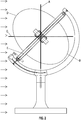
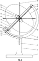
- Figure 1 front view of the wind turbine. The observer is in the direction of the wind.
- Figure 2 profile view of the wind turbine in normal use, in winds of exploitable force, less than Beaufort 7.
- the direction of the wind is indicated by arrows on the left side of the drawing.
- the rotor axis is inclined 45 ° to the vertical.
- Figure 3 profile view of the wind turbine during a storm. The direction of the wind is indicated by arrows on the left side of the drawing. The axis of the rotor is placed vertically.
- the winds exploited by the device have a Beaufort force 1 to 7.
- the blade (A) is fixed on the rotor and is inclined by 45 ° with respect to the axis (E), represented on the figure 2 .
- the axis (E) is itself inclined 45 ° relative to the vertical.
- the blade (A) is thus placed vertically and offers its total surface orthogonal to the wind, which will have maximum efficiency to rotate the rotor. It turns in the direction of the arrow at the top of the figure 1 .
- the total area of the blade (A) offered to the wind is represented on the figure 1 .
- the blade (C) is fixed on the rotor and is also inclined by 45 ° with respect to the axis (E), represented on the figure 2 .
- the blade (C) is diametrically opposed to the blade (A) with respect to the axis (E).
- the inclination of 45 ° of the blade (C) relative to the axis (E) added to the inclination of the axis (E) of 45 ° relative to the vertical causes the blade (C) to end up at 90 ° to the vertical, so horizontal. It is thus parallel to the direction of the wind and offers no hold to it by moving against the wind. This is represented on figures 1 and 2 .
- the blade (D) is fixed on the rotor and is also inclined by 45 ° with respect to the axis (E), as shown on the figures 1 and 2 .
- This blade (D) also participates in rotating the rotor under the force of the wind. It behaves like the blade of a propeller. The force of the wind pushes on the surface of the blade (D) which is inclined. It will then move laterally. This lateral movement is imposed by the inclination of the axis (E) represented on the figure 1 .
- the blade (B) participates in the same way as the blade (D) to rotate the rotor. This is represented on the figure 1 .
- the axis (E) of the rotor is inclined 45 ° relative to the vertical in normal use. Before the arrival of a storm, the inclination of the axis (E) will be brought back to the vertical. This is represented on the figure 3 . Thus, all the blades will offer the same surface to the wind.
- the 4 blades are all inclined 45 ° with respect to the axis (E) and are fixedly mounted on the rotor.
- the system offered to the wind is entirely symmetrical. The wind forces on the blades are identical on each side of the axis. Thus the rotor will stop rotating.
- the wind turbine is equipped with a wind direction detection system and a servomotor which directs the rotor exactly in this direction.
- the wind direction detection system and the servomotor are not shown in the drawings.
- the hoop containing the rotor rotates on the vertical axis of the mast by means of a pin. This is explained in a later chapter.
- the strobe effect is well known on wind turbines. Indeed, the thin blades of the propeller and the large free spaces between the blades cause a strobe effect due to the shadows projected by the sun when the propeller rotates. This strobe effect can harm our well-being.
- the device according to the invention has only a few free spaces between the blades.
- the rotor has the shape of a compact ball. The sun will not project many stroboscopic shadows.
- this wind turbine will have a maximum height of the size of a tree. Thus the shadows due to the rising or setting sun will remain in reasonable dimensions, contrary to the shadows of the propellers which carry very far, because they have height of platform of 100 m.
- This wind turbine is the high torque developed by the rotor. This torque is higher than that of existing propeller and vertical axis wind turbines, for the same diameter of the rotor. This is due to the blade which offers its total surface perpendicular to the wind and the blade on the other side of the axis which is placed parallel to the wind and thus offers no resistance advancing against him. This wind turbine will produce more electricity and will be an investment that will pay off more quickly.
- the rotor has the shape of a compact and spherical ball that will be painted green like the foliage of a tree, and the mast will have the brown color to evoke the trunk of a tree.
- wind turbine Another advantage of the wind turbine is the protection of birds. Crows, buzzards, hawks and storks always land on the tallest tree to observe the surroundings. The wind turbine will be placed near real trees and it will be a few meters lower than these. Thus the birds will not land on the wind turbine but will choose the larger tree next to it, and will not be crushed by the rotor when it turns.
- the device according to the invention comprises a compact rotor in the form of a sphere.
- the blades can not move faster than the wind speed because it is pushing them.
- the end of the blades can move at 400 km / h.
- the end of the blade therefore has a speed several times greater than the wind speed.
- the blades of the propeller move perpendicular to the direction of the wind. The result is noises that can affect our health.
- the device comprises a foundation (1) of reinforced concrete, on which is sealed a vertical mast (2).
- the mast (2) has a vertical axis formed by a pin (3) at three quarters of its height.
- the upper part of the mast (2) with the complete rotor will be able to rotate around the vertical axis, in order to position the wind turbine in the direction of the wind.
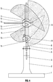
- the mast (2) has a fork at its top, represented on the figure 4 .
- the multiplex plywood arch (4) of the 24 mm thick Multiplex mark acts as a bearing member of the rotor axis which is inclined at 45 ° to the vertical in normal use.
- the hoop (4) is clamped in the fork of the mast (2) by means of two screws (5). These two screws (5) pass through a groove (6) in the arch (4). By unscrewing the screws (5), the hoop can slide in the groove (6) and thus the complete rotor can tilt over a maximum angle of 45 °, and the axis of the rotor will be found in the vertical. This position of the wind turbine will be used during a storm. This is represented on the figure 7 .
- a threaded rod (7) M8 passes through the rotor from one side and is fixed at both ends of the arch (4) by brake nuts (8) which are embedded in countersinks. This threaded rod (7) materializes the axis of the rotor.
- a DN 50 PVC pipe (9) forms the bearing structure of the rotor.
- This tube (9) is traversed from one side by the threaded rod (7) on which are mounted two ball bearings (10) which are held by their inner ring.
- the outer rings of the ball bearings (10) are embedded in the ends of the tube (9).
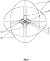
- Two trays (11) plywood brand Multiplex 12 mm thick and octagonal are attached to the tube (9). Between the interstice of these two trays (11) are fixed eight cleats (12) of triangular and isosceles section wood. These cleats (12) have two angles of 45 ° and an angle of 90 °.
- the 4 blades (13) plywood 4 mm thick are arranged at 90 ° relative to each other about the axis of the rotor and they are each fixed by two cleats (12). Two cleats (12) are placed facing each other and hold a blade (13) by clamping on the base of their triangle, which is fixed and thus embedded at an angle of 45 ° to the rotor axis.
- the two cleats (12) are fixed by one of their short sides on the plates (11). This is represented on the figure 5 .
- the four blades (13) have the shape of a semicircle. This is represented on the figure 4 , a front view of the wind turbine, where we can see the complete and real surface of the blade (13) to the right of the axis.
- the complete rotor is thus an entity that has approximately the shape of a sphere.
- a circular plywood tray (14) of the Multiplex mark of thickness 12 mm is fixed on the lower part of the tube (9) of the rotor.
- a dynamo (15) of 6 Volt is fixed on the arch (4).
- the dynamo pinion (15) rotates by contact on the circumference of the plate (14) as the rotor of the wind turbine rotates under the force of the wind.
- the dynamo (15) produces electricity.
- the wind turbine Prior to the arrival of a storm or wind force greater than Beaufort 8, the wind turbine is placed in storm mode.
- the inclination of the rotor axis is brought to the vertical; this is represented on the figure 7 .
- the screws (5) are loosened, then the arch (4) which contains the entire rotor, will slide in the fork of the mast and the screws (5) will slide in the groove (6).
- the axis of the rotor will be placed vertically.
- the screws (5) will be tightened.
- the axis of the rotor being positioned vertically as on the figure 7 all blades will give the same surface to the wind.
- the 4 blades (13) are inclined by 45 ° with respect to the axis of the rotor. They are fixedly mounted on the rotor.
- the system thus offered to the wind is entirely symmetrical.
- the wind forces on the blades are identical on each side of the rotor axis. It will not produce any torque, and it will stop spinning.
- the rotor will have a dimension of the order of 3 m in diameter, and the mast will be 2 m high. This could be the dimensions of a tree-shaped wind turbine, to be installed in the garden.
- the device according to the invention is particularly intended to produce electricity.
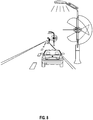
- the wind turbine can be used as a street lamp, in combination with a photovoltaic panel and a lamp located on the top of the arch, and a battery in the trunk, as shown on the figure 8 .
- Streetlights work in autarky thanks to solar energy and wind. Underground wiring connecting streetlights is useless. Streetlights are placed at regular intervals along the highway.
- the rotor is oriented towards the arrival of vehicles, so as to take advantage of the air movement they cause. If the direction of the prevailing winds coincides with the direction of car traffic, then the force of the wind will add up to the air movement of the vehicles and the production of electricity will be increased.
- the battery located in the mast will store the electricity produced by the wind turbine and the photovoltaic panel. The battery will restore electricity for the lighting of the traffic lanes at night.
- the wind turbine can be used as charging station for electric vehicles, in combination with photovoltaic panels placed on the southern part of the trunk, and a battery installed in the trunk, as shown on the figure 9 .
- This wind turbine charging station combined with photovoltaic power works in autarky.
- the battery located in the mast will store the electricity produced by the wind turbine and photovoltaic panels.
- the battery will restore electricity through a socket located in the trunk, to recharge an electric car.
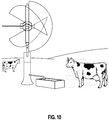
- the wind turbine can be used as a pump to sprinkle cereals in the fields or to bring water into the trough of cattle and sheep, as shown in the diagram. figure 10 .
- a pump will be driven by the rotor. Water from the water table will be pumped. This system works in autarky and is interesting in pastures and fields, where there is no electricity available to power an electric pump.
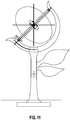
- the wind turbine can be built in the form of a flower, as shown on the figure 11 . It can be installed in the garden.
- the rotor is of two different colors to resemble a sunflower: dark gray in the center symbolizing the nucleus, and yellow on the periphery of the blades symbolizing the petals.
- the hoop and the mast are green.
Landscapes
- Engineering & Computer Science (AREA)
- Life Sciences & Earth Sciences (AREA)
- Sustainable Development (AREA)
- Sustainable Energy (AREA)
- Chemical & Material Sciences (AREA)
- Combustion & Propulsion (AREA)
- Mechanical Engineering (AREA)
- General Engineering & Computer Science (AREA)
- Aviation & Aerospace Engineering (AREA)
- Wind Motors (AREA)
Claims (3)
- Windkraftanlage mit um 45° geneigter Rotorachse gegenüber der Senkrechtachse in Form eines Baums, der sich in die Landschaft eingefügt und mit vier feststehenden Blätter, die um die Achse dieses Rotors herum um 90° versetzt angeordnet sind, die mittels eines Generators Strom erzeugt, umfassend einen vertikalen Mast (2), der in einem Fundament (1) eingespannt ist, dadurch gekennzeichnet, dass ein Bogenrahmen (4), die die tragende Struktur für den Rotor bildet, durch eine Gabel an der Spitze des Mastes (2) gehalten wird, und dass der Bogenrahmen (4) die Achse des Rotors trägt, die um 45° zur Vertikalen geneigt ist, und dass die Achse dieses Rotors aus einem Rohr (9) besteht, das mittels zwei Kugellager (10) auf einer Gewindestange (7) montiert ist, und dass vier Blätter (13) auf dem Rotor befestigt sind und um 45° zur Achse desselben geneigt sind, wobei diese Blätter um die Achse dieses Rotors herum 90° zueinander angeordnet sind und dass das Blatt auf der rechten Seite der Achse seine gesamte Oberfläche senkrecht zu dem Wind aufweist, der es drückt und den Rotor dreht, und dass das Blatt auf der linken Seite, das sich gegen den Wind bewegt somit horizontal positioniert ist und dem Wind keinen Widerstand bietet, und dass sich die beiden anderen Blätter aufgrund ihrer Neigung wie die Blätter eines Propellers verhalten und auch an der Drehung des Rotors teilnehmen, und dass die Windkraftanlage mit einem Windrichtungserfassungssystem und einem Servomotor ausgestattet ist, der den Rotor durch Drehen des Mastes mit einem Stift (3) genau in diese Richtung ausrichtet, und dass während eines Sturms die Neigung der Rotorachse durch die Nut (6) im Bogenrahmen (4) und Schrauben (5) in die Vertikale gebracht wird, und dass somit alle Blätter dem Wind die gleiche Oberfläche bieten, und dass der Rotor aufhört zu drehen, weil er kein Drehmoment mehr erzeugt, und dass die kompakte Kugelform des grünen Rotors an die Blattkrone eines Baumes erinnert, und dass der braune Mast an einen Baumstamm erinnert und dass sich die Windkraftanlage so in die Landschaft einfügt.
- Windkraftanlage nach Anspruch 1, dadurch gekennzeichnet, dass die Windkraftanlage als Ladestation für Elektrofahrzeuge in Kombination mit Photovoltaikmodulen, die auf dem südlichen Teil des Baumstamms angeordnet sind, und einer im Baumstamm installierten Batterie, wobei dieses kombinierte System autark arbeitet und die Batterie den erzeugten Strom der Windturbine und der Photovoltaikmodulen speichert, wobei die Elektrizität von der Batterie über eine im Stamm befindliche Steckdose zurückgeführt wird, um ein Elektroauto zu laden.
- Windkraftanlage nach Anspruch 1, dadurch gekennzeichnet, dass die Form einer Sonnenblume gleicht, und die Windkraftanlage eine Rotorachse hat, die um 45° zur Senkrechtachse geneigt ist, und mit vier feststehenden Blätter, die um die Achse dieses Rotors herum um 90° versetzt angeordnet sind, die mittels eines Generators Strom erzeugt, umfassend einen vertikalen Mast (2), der in einem Fundament (1) eingespannt ist, dadurch gekennzeichnet, dass ein Bogenrahmen (4), die die tragende Struktur für den Rotor bildet, durch eine Gabel an der Spitze des Mastes (2) gehalten wird, und dass der Bogenrahmen (4) die Achse des Rotors trägt, die um 45° zur Vertikalen geneigt ist, und dass die Achse dieses Rotors aus einem Rohr (9) besteht, das mittels zwei Kugellager (10) auf einer Gewindestange (7) montiert ist, und dass vier Blätter (13) auf dem Rotor befestigt sind und um 45° zur Achse desselben geneigt sind, wobei diese Blätter um die Achse dieses Rotors herum 90° zueinander angeordnet sind und dass das Blatt auf der rechten Seite der Achse seine gesamte Oberfläche senkrecht zu dem Wind aufweist, der es drückt und den Rotor dreht, und dass das Blatt auf der linken Seite, das sich gegen den Wind bewegt somit horizontal positioniert ist und dem Wind keinen Widerstand bietet, und dass sich die beiden anderen Blätter aufgrund ihrer Neigung wie die Blätter eines Propellers verhalten und auch an der Drehung des Rotors teilnehmen, und dass die Windkraftanlage mit einem Windrichtungserfassungssystem und einem Servomotor ausgestattet ist, der den Rotor durch Drehen des Mastes mit einem Stift (3) genau in diese Richtung ausrichtet, und dass während eines Sturms die Neigung der Rotorachse durch die Nut (6) im Bogenrahmen (4) und Schrauben (5) in die Vertikale gebracht wird, und dass somit alle Blätter dem Wind die gleiche Oberfläche bieten, und dass der Rotor aufhört zu drehen, weil er kein Drehmoment mehr erzeugt, und dass die kompakte Kugelform des Rotors zwei verschiedene Farben aufweist, um einer Sonnenblume zu ähneln, nämlich dunkelgrau in der Mitte, die den Kern symbolisiert, und gelb am Umfang der Blätter, die die Blütenblätter symbolisieren, und dass der Bogenrahmen und der Mast eine grüne Farbe aufweisen, und dass zwei am Mast befestigte Blätter als Wetterfahne dienen, um den Rotor in die Windrichtung zu lenken, wobei sich der Mast dank des Stiftes um seine vertikale Achse dreht, und dass diese sonnenblumenförmige Windturbine im Garten installiert werden kann um Strom zu erzeugen.
Applications Claiming Priority (1)
| Application Number | Priority Date | Filing Date | Title |
|---|---|---|---|
| FR1700575A FR3066790B1 (fr) | 2017-05-29 | 2017-05-29 | Eolienne a axe de rotor incline a 45° par rapport a la verticale en forme d'arbre s'integrant dans les paysages |
Publications (2)
| Publication Number | Publication Date |
|---|---|
| EP3409941A1 EP3409941A1 (de) | 2018-12-05 |
| EP3409941B1 true EP3409941B1 (de) | 2019-09-25 |
Family
ID=60019945
Family Applications (1)
| Application Number | Title | Priority Date | Filing Date |
|---|---|---|---|
| EP18020127.9A Active EP3409941B1 (de) | 2017-05-29 | 2018-03-29 | Windkraftanlage mit um 45° geneigter rotorachse gegenüber der senkrechtachse in form eines baums, der sich in die landschaft einfügt |
Country Status (2)
| Country | Link |
|---|---|
| EP (1) | EP3409941B1 (de) |
| FR (1) | FR3066790B1 (de) |
Families Citing this family (2)
| Publication number | Priority date | Publication date | Assignee | Title |
|---|---|---|---|---|
| FR3111675B1 (fr) * | 2020-06-22 | 2022-06-10 | Bernaud Alain | dispositif d’effacement vertical de l’unité de production d’électricité d’une éolienne à axe horizontal dans le but de protéger cette machine des vents puissants et dommageables rencontrés. |
| CN115110446B (zh) * | 2022-07-19 | 2023-07-18 | 西南石油大学 | 一种高陡边坡危岩落石防护网系统 |
Family Cites Families (3)
| Publication number | Priority date | Publication date | Assignee | Title |
|---|---|---|---|---|
| US3187816A (en) * | 1962-12-28 | 1965-06-08 | Herman G A Winter | Fluid power screw |
| SE0701311L (sv) * | 2007-05-31 | 2008-12-01 | Nilsson Goran Alfred | Rotor för vindrotor |
| CN103328815B (zh) * | 2010-08-11 | 2018-05-04 | 木星水利有限公司 | 用于从流体的流动水流中产生电能的系统和方法 |
-
2017
- 2017-05-29 FR FR1700575A patent/FR3066790B1/fr active Active
-
2018
- 2018-03-29 EP EP18020127.9A patent/EP3409941B1/de active Active
Also Published As
| Publication number | Publication date |
|---|---|
| EP3409941A1 (de) | 2018-12-05 |
| FR3066790B1 (fr) | 2019-06-21 |
| FR3066790A1 (fr) | 2018-11-30 |
Similar Documents
| Publication | Publication Date | Title |
|---|---|---|
| CA2719144C (fr) | Pale pour appareil de generation d'energie, a partir d'un fluide, et appareil comprenant un rotor faisant application de telles pales | |
| FR3066790B1 (fr) | Eolienne a axe de rotor incline a 45° par rapport a la verticale en forme d'arbre s'integrant dans les paysages | |
| FR2982649A1 (fr) | Dispositif de recuperation d'energie a partir d'un fluide en mouvement | |
| CA2523420A1 (fr) | Eolienne carenee auto-orientable | |
| CA2636860A1 (fr) | Aerogenerateur a axe horizontal | |
| WO2009003285A1 (fr) | Eolienne à axe verticale avec pales munies d'un moyen de rappel | |
| WO2003103113A3 (de) | Vertikaler rotor mit lenkbaren flügel | |
| EP2610483A1 (de) | Vertical-axis wind turbine | |
| CN103478116A (zh) | 一种综合驱鸟装置 | |
| CA2755083A1 (fr) | Rotor pour generateur d'energie, en particulier pour eoliennes. | |
| FR2461832A1 (fr) | Dispositif pour la production d'energie de consommation a partir du vent et/ou du soleil | |
| FR3028895A1 (fr) | Dispositif de production d'energie de type eolienne. | |
| FR2600118A1 (fr) | Eolienne speciale conique transparente remplacant le toit d'un immeuble | |
| FR2500076A1 (fr) | Eolienne independante de la direction du vent | |
| EP0357740A1 (de) | Wind-turbogenerator. | |
| WO2018127630A1 (fr) | Eolienne ou hydrolienne à effet vortex et séquence de compression-basculement-éjection latérale extérieure d'un fluide incident, face à l'hélice | |
| FR2902157A1 (fr) | Eolienne a axe vertical comprenant une turbine et une gaine co-axiale a ladite turbine et enveloppant cette derniere | |
| FR2962172A1 (fr) | Eolienne verticale a winglets | |
| FR3027069A1 (fr) | Eolienne a axe vertical en forme d'arbre s'integrant dans les paysages, et qui produit de l'electricite | |
| CA2628592A1 (fr) | Eollenne a axe vertical | |
| CH707974A2 (fr) | Ensemble pour capter l'énergie du vent et pour la transformer en énergie utilisable. | |
| CN217407566U (zh) | 一种全天有效驱鸟器 | |
| CN212184874U (zh) | 一种大樱桃种植用驱鸟装置 | |
| FR3132547A1 (fr) | Eolienne à axe vertical, et navire équipé d’au moins une telle éolienne | |
| EP3983669B1 (de) | Windturbine und energieumwandlungsanlage mit einer solchen windenergieanlage |
Legal Events
| Date | Code | Title | Description |
|---|---|---|---|
| PUAI | Public reference made under article 153(3) epc to a published international application that has entered the european phase |
Free format text: ORIGINAL CODE: 0009012 |
|
| STAA | Information on the status of an ep patent application or granted ep patent |
Free format text: STATUS: REQUEST FOR EXAMINATION WAS MADE |
|
| 17P | Request for examination filed |
Effective date: 20180403 |
|
| AK | Designated contracting states |
Kind code of ref document: A1 Designated state(s): AL AT BE BG CH CY CZ DE DK EE ES FI FR GB GR HR HU IE IS IT LI LT LU LV MC MK MT NL NO PL PT RO RS SE SI SK SM TR |
|
| AX | Request for extension of the european patent |
Extension state: BA ME |
|
| RBV | Designated contracting states (corrected) |
Designated state(s): AL AT BE BG CH CY CZ DE DK EE ES FI FR GB GR HR HU IE IS IT LI LT LU LV MC MK MT NL NO PL PT RO RS SE SI SK SM TR |
|
| GRAP | Despatch of communication of intention to grant a patent |
Free format text: ORIGINAL CODE: EPIDOSNIGR1 |
|
| STAA | Information on the status of an ep patent application or granted ep patent |
Free format text: STATUS: GRANT OF PATENT IS INTENDED |
|
| INTG | Intention to grant announced |
Effective date: 20190425 |
|
| GRAS | Grant fee paid |
Free format text: ORIGINAL CODE: EPIDOSNIGR3 |
|
| GRAA | (expected) grant |
Free format text: ORIGINAL CODE: 0009210 |
|
| STAA | Information on the status of an ep patent application or granted ep patent |
Free format text: STATUS: THE PATENT HAS BEEN GRANTED |
|
| AK | Designated contracting states |
Kind code of ref document: B1 Designated state(s): AL AT BE BG CH CY CZ DE DK EE ES FI FR GB GR HR HU IE IS IT LI LT LU LV MC MK MT NL NO PL PT RO RS SE SI SK SM TR |
|
| REG | Reference to a national code |
Ref country code: GB Ref legal event code: FG4D Free format text: NOT ENGLISH |
|
| REG | Reference to a national code |
Ref country code: CH Ref legal event code: EP |
|
| REG | Reference to a national code |
Ref country code: AT Ref legal event code: REF Ref document number: 1184065 Country of ref document: AT Kind code of ref document: T Effective date: 20191015 |
|
| REG | Reference to a national code |
Ref country code: IE Ref legal event code: FG4D Free format text: LANGUAGE OF EP DOCUMENT: FRENCH |
|
| REG | Reference to a national code |
Ref country code: DE Ref legal event code: R096 Ref document number: 602018000691 Country of ref document: DE |
|
| REG | Reference to a national code |
Ref country code: NL Ref legal event code: MP Effective date: 20190925 |
|
| PG25 | Lapsed in a contracting state [announced via postgrant information from national office to epo] |
Ref country code: SE Free format text: LAPSE BECAUSE OF FAILURE TO SUBMIT A TRANSLATION OF THE DESCRIPTION OR TO PAY THE FEE WITHIN THE PRESCRIBED TIME-LIMIT Effective date: 20190925 Ref country code: NO Free format text: LAPSE BECAUSE OF FAILURE TO SUBMIT A TRANSLATION OF THE DESCRIPTION OR TO PAY THE FEE WITHIN THE PRESCRIBED TIME-LIMIT Effective date: 20191225 Ref country code: FI Free format text: LAPSE BECAUSE OF FAILURE TO SUBMIT A TRANSLATION OF THE DESCRIPTION OR TO PAY THE FEE WITHIN THE PRESCRIBED TIME-LIMIT Effective date: 20190925 Ref country code: BG Free format text: LAPSE BECAUSE OF FAILURE TO SUBMIT A TRANSLATION OF THE DESCRIPTION OR TO PAY THE FEE WITHIN THE PRESCRIBED TIME-LIMIT Effective date: 20191225 Ref country code: HR Free format text: LAPSE BECAUSE OF FAILURE TO SUBMIT A TRANSLATION OF THE DESCRIPTION OR TO PAY THE FEE WITHIN THE PRESCRIBED TIME-LIMIT Effective date: 20190925 Ref country code: LT Free format text: LAPSE BECAUSE OF FAILURE TO SUBMIT A TRANSLATION OF THE DESCRIPTION OR TO PAY THE FEE WITHIN THE PRESCRIBED TIME-LIMIT Effective date: 20190925 |
|
| REG | Reference to a national code |
Ref country code: LT Ref legal event code: MG4D |
|
| PG25 | Lapsed in a contracting state [announced via postgrant information from national office to epo] |
Ref country code: RS Free format text: LAPSE BECAUSE OF FAILURE TO SUBMIT A TRANSLATION OF THE DESCRIPTION OR TO PAY THE FEE WITHIN THE PRESCRIBED TIME-LIMIT Effective date: 20190925 Ref country code: LV Free format text: LAPSE BECAUSE OF FAILURE TO SUBMIT A TRANSLATION OF THE DESCRIPTION OR TO PAY THE FEE WITHIN THE PRESCRIBED TIME-LIMIT Effective date: 20190925 |
|
| REG | Reference to a national code |
Ref country code: AT Ref legal event code: MK05 Ref document number: 1184065 Country of ref document: AT Kind code of ref document: T Effective date: 20190925 |
|
| PG25 | Lapsed in a contracting state [announced via postgrant information from national office to epo] |
Ref country code: PL Free format text: LAPSE BECAUSE OF FAILURE TO SUBMIT A TRANSLATION OF THE DESCRIPTION OR TO PAY THE FEE WITHIN THE PRESCRIBED TIME-LIMIT Effective date: 20190925 Ref country code: NL Free format text: LAPSE BECAUSE OF FAILURE TO SUBMIT A TRANSLATION OF THE DESCRIPTION OR TO PAY THE FEE WITHIN THE PRESCRIBED TIME-LIMIT Effective date: 20190925 Ref country code: ES Free format text: LAPSE BECAUSE OF FAILURE TO SUBMIT A TRANSLATION OF THE DESCRIPTION OR TO PAY THE FEE WITHIN THE PRESCRIBED TIME-LIMIT Effective date: 20190925 Ref country code: PT Free format text: LAPSE BECAUSE OF FAILURE TO SUBMIT A TRANSLATION OF THE DESCRIPTION OR TO PAY THE FEE WITHIN THE PRESCRIBED TIME-LIMIT Effective date: 20200127 Ref country code: AL Free format text: LAPSE BECAUSE OF FAILURE TO SUBMIT A TRANSLATION OF THE DESCRIPTION OR TO PAY THE FEE WITHIN THE PRESCRIBED TIME-LIMIT Effective date: 20190925 Ref country code: RO Free format text: LAPSE BECAUSE OF FAILURE TO SUBMIT A TRANSLATION OF THE DESCRIPTION OR TO PAY THE FEE WITHIN THE PRESCRIBED TIME-LIMIT Effective date: 20190925 Ref country code: AT Free format text: LAPSE BECAUSE OF FAILURE TO SUBMIT A TRANSLATION OF THE DESCRIPTION OR TO PAY THE FEE WITHIN THE PRESCRIBED TIME-LIMIT Effective date: 20190925 Ref country code: IT Free format text: LAPSE BECAUSE OF FAILURE TO SUBMIT A TRANSLATION OF THE DESCRIPTION OR TO PAY THE FEE WITHIN THE PRESCRIBED TIME-LIMIT Effective date: 20190925 Ref country code: EE Free format text: LAPSE BECAUSE OF FAILURE TO SUBMIT A TRANSLATION OF THE DESCRIPTION OR TO PAY THE FEE WITHIN THE PRESCRIBED TIME-LIMIT Effective date: 20190925 |
|
| PG25 | Lapsed in a contracting state [announced via postgrant information from national office to epo] |
Ref country code: SM Free format text: LAPSE BECAUSE OF FAILURE TO SUBMIT A TRANSLATION OF THE DESCRIPTION OR TO PAY THE FEE WITHIN THE PRESCRIBED TIME-LIMIT Effective date: 20190925 Ref country code: CZ Free format text: LAPSE BECAUSE OF FAILURE TO SUBMIT A TRANSLATION OF THE DESCRIPTION OR TO PAY THE FEE WITHIN THE PRESCRIBED TIME-LIMIT Effective date: 20190925 Ref country code: SK Free format text: LAPSE BECAUSE OF FAILURE TO SUBMIT A TRANSLATION OF THE DESCRIPTION OR TO PAY THE FEE WITHIN THE PRESCRIBED TIME-LIMIT Effective date: 20190925 Ref country code: IS Free format text: LAPSE BECAUSE OF FAILURE TO SUBMIT A TRANSLATION OF THE DESCRIPTION OR TO PAY THE FEE WITHIN THE PRESCRIBED TIME-LIMIT Effective date: 20200224 |
|
| REG | Reference to a national code |
Ref country code: DE Ref legal event code: R097 Ref document number: 602018000691 Country of ref document: DE |
|
| PG2D | Information on lapse in contracting state deleted |
Ref country code: IS |
|
| PG25 | Lapsed in a contracting state [announced via postgrant information from national office to epo] |
Ref country code: DK Free format text: LAPSE BECAUSE OF FAILURE TO SUBMIT A TRANSLATION OF THE DESCRIPTION OR TO PAY THE FEE WITHIN THE PRESCRIBED TIME-LIMIT Effective date: 20190925 Ref country code: IS Free format text: LAPSE BECAUSE OF FAILURE TO SUBMIT A TRANSLATION OF THE DESCRIPTION OR TO PAY THE FEE WITHIN THE PRESCRIBED TIME-LIMIT Effective date: 20200126 |
|
| PLBE | No opposition filed within time limit |
Free format text: ORIGINAL CODE: 0009261 |
|
| STAA | Information on the status of an ep patent application or granted ep patent |
Free format text: STATUS: NO OPPOSITION FILED WITHIN TIME LIMIT |
|
| 26N | No opposition filed |
Effective date: 20200626 |
|
| PG25 | Lapsed in a contracting state [announced via postgrant information from national office to epo] |
Ref country code: MC Free format text: LAPSE BECAUSE OF FAILURE TO SUBMIT A TRANSLATION OF THE DESCRIPTION OR TO PAY THE FEE WITHIN THE PRESCRIBED TIME-LIMIT Effective date: 20190925 |
|
| PG25 | Lapsed in a contracting state [announced via postgrant information from national office to epo] |
Ref country code: SI Free format text: LAPSE BECAUSE OF FAILURE TO SUBMIT A TRANSLATION OF THE DESCRIPTION OR TO PAY THE FEE WITHIN THE PRESCRIBED TIME-LIMIT Effective date: 20190925 |
|
| PGFP | Annual fee paid to national office [announced via postgrant information from national office to epo] |
Ref country code: IE Payment date: 20210302 Year of fee payment: 4 Ref country code: LU Payment date: 20210316 Year of fee payment: 4 |
|
| PGFP | Annual fee paid to national office [announced via postgrant information from national office to epo] |
Ref country code: BE Payment date: 20210301 Year of fee payment: 4 |
|
| REG | Reference to a national code |
Ref country code: CH Ref legal event code: PL |
|
| PG25 | Lapsed in a contracting state [announced via postgrant information from national office to epo] |
Ref country code: LI Free format text: LAPSE BECAUSE OF NON-PAYMENT OF DUE FEES Effective date: 20210331 Ref country code: CH Free format text: LAPSE BECAUSE OF NON-PAYMENT OF DUE FEES Effective date: 20210331 |
|
| PG25 | Lapsed in a contracting state [announced via postgrant information from national office to epo] |
Ref country code: TR Free format text: LAPSE BECAUSE OF FAILURE TO SUBMIT A TRANSLATION OF THE DESCRIPTION OR TO PAY THE FEE WITHIN THE PRESCRIBED TIME-LIMIT Effective date: 20190925 Ref country code: MT Free format text: LAPSE BECAUSE OF FAILURE TO SUBMIT A TRANSLATION OF THE DESCRIPTION OR TO PAY THE FEE WITHIN THE PRESCRIBED TIME-LIMIT Effective date: 20190925 Ref country code: CY Free format text: LAPSE BECAUSE OF FAILURE TO SUBMIT A TRANSLATION OF THE DESCRIPTION OR TO PAY THE FEE WITHIN THE PRESCRIBED TIME-LIMIT Effective date: 20190925 |
|
| PGFP | Annual fee paid to national office [announced via postgrant information from national office to epo] |
Ref country code: FR Payment date: 20220306 Year of fee payment: 5 |
|
| PG25 | Lapsed in a contracting state [announced via postgrant information from national office to epo] |
Ref country code: MK Free format text: LAPSE BECAUSE OF FAILURE TO SUBMIT A TRANSLATION OF THE DESCRIPTION OR TO PAY THE FEE WITHIN THE PRESCRIBED TIME-LIMIT Effective date: 20190925 |
|
| PG25 | Lapsed in a contracting state [announced via postgrant information from national office to epo] |
Ref country code: GR Free format text: LAPSE BECAUSE OF FAILURE TO SUBMIT A TRANSLATION OF THE DESCRIPTION OR TO PAY THE FEE WITHIN THE PRESCRIBED TIME-LIMIT Effective date: 20190925 |
|
| GBPC | Gb: european patent ceased through non-payment of renewal fee |
Effective date: 20220329 |
|
| REG | Reference to a national code |
Ref country code: BE Ref legal event code: MM Effective date: 20220331 |
|
| PG25 | Lapsed in a contracting state [announced via postgrant information from national office to epo] |
Ref country code: LU Free format text: LAPSE BECAUSE OF NON-PAYMENT OF DUE FEES Effective date: 20220329 Ref country code: IE Free format text: LAPSE BECAUSE OF NON-PAYMENT OF DUE FEES Effective date: 20220329 Ref country code: GB Free format text: LAPSE BECAUSE OF NON-PAYMENT OF DUE FEES Effective date: 20220329 |
|
| PG25 | Lapsed in a contracting state [announced via postgrant information from national office to epo] |
Ref country code: BE Free format text: LAPSE BECAUSE OF NON-PAYMENT OF DUE FEES Effective date: 20220331 |
|
| PG25 | Lapsed in a contracting state [announced via postgrant information from national office to epo] |
Ref country code: FR Free format text: LAPSE BECAUSE OF NON-PAYMENT OF DUE FEES Effective date: 20230331 |
|
| PGFP | Annual fee paid to national office [announced via postgrant information from national office to epo] |
Ref country code: DE Payment date: 20240318 Year of fee payment: 7 |
|
| REG | Reference to a national code |
Ref country code: DE Ref legal event code: R119 Ref document number: 602018000691 Country of ref document: DE |
|
| PG25 | Lapsed in a contracting state [announced via postgrant information from national office to epo] |
Ref country code: DE Free format text: LAPSE BECAUSE OF NON-PAYMENT OF DUE FEES Effective date: 20251001 |