EP3409959A1 - Mécanisme de déploiement pliable - Google Patents
Mécanisme de déploiement pliable Download PDFInfo
- Publication number
- EP3409959A1 EP3409959A1 EP17743755.5A EP17743755A EP3409959A1 EP 3409959 A1 EP3409959 A1 EP 3409959A1 EP 17743755 A EP17743755 A EP 17743755A EP 3409959 A1 EP3409959 A1 EP 3409959A1
- Authority
- EP
- European Patent Office
- Prior art keywords
- connecting rod
- hinged
- folding
- sleeve
- unfolding
- Prior art date
- Legal status (The legal status is an assumption and is not a legal conclusion. Google has not performed a legal analysis and makes no representation as to the accuracy of the status listed.)
- Granted
Links
Images


Classifications
-
- E—FIXED CONSTRUCTIONS
- E05—LOCKS; KEYS; WINDOW OR DOOR FITTINGS; SAFES
- E05D—HINGES OR SUSPENSION DEVICES FOR DOORS, WINDOWS OR WINGS
- E05D15/00—Suspension arrangements for wings
- E05D15/26—Suspension arrangements for wings for folding wings
-
- F—MECHANICAL ENGINEERING; LIGHTING; HEATING; WEAPONS; BLASTING
- F16—ENGINEERING ELEMENTS AND UNITS; GENERAL MEASURES FOR PRODUCING AND MAINTAINING EFFECTIVE FUNCTIONING OF MACHINES OR INSTALLATIONS; THERMAL INSULATION IN GENERAL
- F16C—SHAFTS; FLEXIBLE SHAFTS; ELEMENTS OR CRANKSHAFT MECHANISMS; ROTARY BODIES OTHER THAN GEARING ELEMENTS; BEARINGS
- F16C11/00—Pivots; Pivotal connections
- F16C11/04—Pivotal connections
- F16C11/10—Arrangements for locking
-
- E—FIXED CONSTRUCTIONS
- E05—LOCKS; KEYS; WINDOW OR DOOR FITTINGS; SAFES
- E05D—HINGES OR SUSPENSION DEVICES FOR DOORS, WINDOWS OR WINGS
- E05D3/00—Hinges with pins
- E05D3/06—Hinges with pins with two or more pins
-
- E—FIXED CONSTRUCTIONS
- E05—LOCKS; KEYS; WINDOW OR DOOR FITTINGS; SAFES
- E05F—DEVICES FOR MOVING WINGS INTO OPEN OR CLOSED POSITION; CHECKS FOR WINGS; WING FITTINGS NOT OTHERWISE PROVIDED FOR, CONCERNED WITH THE FUNCTIONING OF THE WING
- E05F3/00—Closers or openers with braking devices, e.g. checks; Construction of pneumatic or liquid braking devices
- E05F3/20—Closers or openers with braking devices, e.g. checks; Construction of pneumatic or liquid braking devices in hinges
-
- F—MECHANICAL ENGINEERING; LIGHTING; HEATING; WEAPONS; BLASTING
- F16—ENGINEERING ELEMENTS AND UNITS; GENERAL MEASURES FOR PRODUCING AND MAINTAINING EFFECTIVE FUNCTIONING OF MACHINES OR INSTALLATIONS; THERMAL INSULATION IN GENERAL
- F16C—SHAFTS; FLEXIBLE SHAFTS; ELEMENTS OR CRANKSHAFT MECHANISMS; ROTARY BODIES OTHER THAN GEARING ELEMENTS; BEARINGS
- F16C11/00—Pivots; Pivotal connections
- F16C11/04—Pivotal connections
-
- E—FIXED CONSTRUCTIONS
- E05—LOCKS; KEYS; WINDOW OR DOOR FITTINGS; SAFES
- E05F—DEVICES FOR MOVING WINGS INTO OPEN OR CLOSED POSITION; CHECKS FOR WINGS; WING FITTINGS NOT OTHERWISE PROVIDED FOR, CONCERNED WITH THE FUNCTIONING OF THE WING
- E05F1/00—Closers or openers for wings, not otherwise provided for in this subclass
- E05F1/08—Closers or openers for wings, not otherwise provided for in this subclass spring-actuated, e.g. for horizontally sliding wings
- E05F1/10—Closers or openers for wings, not otherwise provided for in this subclass spring-actuated, e.g. for horizontally sliding wings for swinging wings, e.g. counterbalance
- E05F1/1041—Closers or openers for wings, not otherwise provided for in this subclass spring-actuated, e.g. for horizontally sliding wings for swinging wings, e.g. counterbalance with a coil spring perpendicular to the pivot axis
- E05F1/105—Closers or openers for wings, not otherwise provided for in this subclass spring-actuated, e.g. for horizontally sliding wings for swinging wings, e.g. counterbalance with a coil spring perpendicular to the pivot axis with a compression spring
- E05F1/1058—Closers or openers for wings, not otherwise provided for in this subclass spring-actuated, e.g. for horizontally sliding wings for swinging wings, e.g. counterbalance with a coil spring perpendicular to the pivot axis with a compression spring for counterbalancing
-
- E—FIXED CONSTRUCTIONS
- E05—LOCKS; KEYS; WINDOW OR DOOR FITTINGS; SAFES
- E05F—DEVICES FOR MOVING WINGS INTO OPEN OR CLOSED POSITION; CHECKS FOR WINGS; WING FITTINGS NOT OTHERWISE PROVIDED FOR, CONCERNED WITH THE FUNCTIONING OF THE WING
- E05F1/00—Closers or openers for wings, not otherwise provided for in this subclass
- E05F1/08—Closers or openers for wings, not otherwise provided for in this subclass spring-actuated, e.g. for horizontally sliding wings
- E05F1/10—Closers or openers for wings, not otherwise provided for in this subclass spring-actuated, e.g. for horizontally sliding wings for swinging wings, e.g. counterbalance
- E05F1/1091—Closers or openers for wings, not otherwise provided for in this subclass spring-actuated, e.g. for horizontally sliding wings for swinging wings, e.g. counterbalance with a gas spring
-
- E—FIXED CONSTRUCTIONS
- E05—LOCKS; KEYS; WINDOW OR DOOR FITTINGS; SAFES
- E05F—DEVICES FOR MOVING WINGS INTO OPEN OR CLOSED POSITION; CHECKS FOR WINGS; WING FITTINGS NOT OTHERWISE PROVIDED FOR, CONCERNED WITH THE FUNCTIONING OF THE WING
- E05F15/00—Power-operated mechanisms for wings
- E05F15/50—Power-operated mechanisms for wings using fluid-pressure actuators
- E05F15/51—Power-operated mechanisms for wings using fluid-pressure actuators for folding wings
-
- E—FIXED CONSTRUCTIONS
- E05—LOCKS; KEYS; WINDOW OR DOOR FITTINGS; SAFES
- E05Y—INDEXING SCHEME ASSOCIATED WITH SUBCLASSES E05D AND E05F, RELATING TO CONSTRUCTION ELEMENTS, ELECTRIC CONTROL, POWER SUPPLY, POWER SIGNAL OR TRANSMISSION, USER INTERFACES, MOUNTING OR COUPLING, DETAILS, ACCESSORIES, AUXILIARY OPERATIONS NOT OTHERWISE PROVIDED FOR, APPLICATION THEREOF
- E05Y2201/00—Constructional elements; Accessories therefor
- E05Y2201/40—Motors; Magnets; Springs; Weights; Accessories therefor
- E05Y2201/47—Springs
- E05Y2201/478—Gas springs
-
- E—FIXED CONSTRUCTIONS
- E05—LOCKS; KEYS; WINDOW OR DOOR FITTINGS; SAFES
- E05Y—INDEXING SCHEME ASSOCIATED WITH SUBCLASSES E05D AND E05F, RELATING TO CONSTRUCTION ELEMENTS, ELECTRIC CONTROL, POWER SUPPLY, POWER SIGNAL OR TRANSMISSION, USER INTERFACES, MOUNTING OR COUPLING, DETAILS, ACCESSORIES, AUXILIARY OPERATIONS NOT OTHERWISE PROVIDED FOR, APPLICATION THEREOF
- E05Y2201/00—Constructional elements; Accessories therefor
- E05Y2201/60—Suspension or transmission members; Accessories therefor
- E05Y2201/622—Suspension or transmission members elements
- E05Y2201/624—Arms
-
- E—FIXED CONSTRUCTIONS
- E05—LOCKS; KEYS; WINDOW OR DOOR FITTINGS; SAFES
- E05Y—INDEXING SCHEME ASSOCIATED WITH SUBCLASSES E05D AND E05F, RELATING TO CONSTRUCTION ELEMENTS, ELECTRIC CONTROL, POWER SUPPLY, POWER SIGNAL OR TRANSMISSION, USER INTERFACES, MOUNTING OR COUPLING, DETAILS, ACCESSORIES, AUXILIARY OPERATIONS NOT OTHERWISE PROVIDED FOR, APPLICATION THEREOF
- E05Y2800/00—Details, accessories and auxiliary operations not otherwise provided for
-
- E—FIXED CONSTRUCTIONS
- E05—LOCKS; KEYS; WINDOW OR DOOR FITTINGS; SAFES
- E05Y—INDEXING SCHEME ASSOCIATED WITH SUBCLASSES E05D AND E05F, RELATING TO CONSTRUCTION ELEMENTS, ELECTRIC CONTROL, POWER SUPPLY, POWER SIGNAL OR TRANSMISSION, USER INTERFACES, MOUNTING OR COUPLING, DETAILS, ACCESSORIES, AUXILIARY OPERATIONS NOT OTHERWISE PROVIDED FOR, APPLICATION THEREOF
- E05Y2900/00—Application of doors, windows, wings or fittings thereof
- E05Y2900/50—Application of doors, windows, wings or fittings thereof for vehicles
- E05Y2900/512—Application of doors, windows, wings or fittings thereof for vehicles for recreational vehicles
Definitions
- the invention relates to a technical field of auxiliary structure for panel hinge, and more particularly, to a folding and unfolding mechanism.
- a hinge is needed when joint connection is involved in two large panels, and a certain power system is necessary for supporting stress and completing folding and unfolding of the panels.
- the folding and unfolding mechanism occupies larger space when performing mutually folding and unfolding of 0-180 degrees between two panels, and the mechanism is relatively complex, thus, the mechanism does not work very well in many applications. Therefore, there is a need for an improved folding and unfolding mechanism with simple structure, taking up less space, to solve the above problems existing in the prior art.
- the present invention provides a folding and unfolding mechanism.
- a folding and unfolding mechanism mounted between an upper panel and a lower panel which are hinged together, for folding and unfolding the upper panel and the lower panel, and for overturning for 0-180 degrees between the upper panel and the lower panel, comprising:
- the above folding and unfolding mechanism further comprises:
- the above folding and unfolding mechanism wherein the inner sleeve, the middle sleeve and the outer sleeve can slide relatively to each other, and the start skid has an arc surface at a side relative to the other end of the outer sleeve, the arc surface being facing the upper panel.
- the folding and unfolding mechanism wherein a first convex edge, extending in the form of rib, forms at one side of the first connecting rod, and a second convex edge opposite to the first convex edge is arranged on a surface of the upper panel facing the lower panel;
- the third connecting rod is generally in the form of triangle, wherein two angles are provided with the first hinged joint and the second hinged joint, respectively, and the third angle is between the first convex edge and the second convex edge when the folding and unfolding mechanism is in a folded state, and abuts against the second convex edge to push the upper panel to perform pre-unfolding when the mechanism is unfolding, moreover, the third angle of the third connecting rod is arc-shaped or is provided with a roller.
- the above folding and unfolding mechanism wherein the first hinged joint extends outwards, forming a projection, and when the folding and unfolding mechanism is folding and unfolding, the projection abuts against one side of the fourth connecting rod to limit a relative position of the third connecting rod and the fourth connecting rod.
- the present invention has the following beneficial effects when compared to the prior art:
- the term "plurality” means a number greater than one.
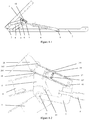
- Figure 1-1 is a schematic view of a folding and unfolding mechanism of the present invention
- Figure 1-2 is a partially enlarged view of a folding and unfolding mechanism of the present invention
- Figure 1-3 is a 90-degree folding schematic view of a folding and unfolding mechanism of the present invention.
- Figures 1-1, 1-2 and 1-3 show a folding and unfolding mechanism of a preferred embodiment, which is mounted between an upper panel 1 and a lower panel 2 which are hinged together, for folding and unfolding the upper panel 1 and the lower panel 2, and for overturning for 0-180 degrees between the upper panel 1 and the lower panel 2.
- the folding and unfolding mechanism comprises: a four-connecting-rod assembly, comprising a first connecting rod 4, a second connecting rod 5, a third connecting rod 6 and a fourth connecting rod 7, one end of the first connecting rod 4 being hinged to one end of the second connecting rod 5, the other end of the first connecting rod 4 being hinged to the upper panel 1, the other end of the second connecting rod 5 being hinged to the lower panel 2, and a first hinged joint 10 being formed at a hinged ends of the first connecting rod 4and the second connecting rod 5, a middle part of the third connecting rod 6 is hinged to the first connecting rod 4 and the second connecting rod 5 through the first hinged joint 10, the third connecting rod 6 having a second hinged joint 11 at one end, one end of the fourth connecting rod 7 being hinged to the third connecting rod 6 through the second hinged joint 11, the third connecting rod 6 being provided with a third hinged joint 181 relative to the other end of the first hinged joint 10.
- the folding and unfolding mechanism comprises: a pushrod assembly, comprising a pushrod 8 and a pushing portion 9, wherein the pushrod 8 is fixedly connected to an other side, which is relative to the third connecting rod 6, of the fourth connecting rod 7 at one end, and the pushrod 8 is connected to the pushing portion 9 at the other end, the pushing portion 9 being mounted above the lower panel 2 for driving the pushrod 8 to move.
- the folding and unfolding mechanism comprises: an axial locking mechanism, comprising an inner sleeve 16, a middle sleeve 17 and an outer sleeve 18, wherein the middle sleeve 17 is sleeved outside the inner sleeve 16, while the outer sleeve 18 is sleeved outside the middle sleeve 17, and the interior of the inner sleeve 16 is provided with two pawls 19, one end of each of the two pawls 19 is hinged to each other through a positioning shaft 191 rotatablely connected to an inner wall of two sides of the inner sleeve 16, also, the two pawls 19 having a compression spring 192 at the other end, the two pawls 19 are fixed at respective positions in the inner sleeve 17 by the positioning shaft 191.
- the compression spring 192 ensures the normal opening angle of the pawls 19, and the middle sleeve 17 may control the opening and closing movements of the paw
- one end of the inner sleeve 16 is hinged to the other end, relative to the third connecting rod 6, of the fourth connecting rod 7, and one end of the outer sleeve 18 is hinged to the third connecting rod 6 through the third hinged joint 181;
- the folding and unfolding mechanism comprises: a start skid 20, hinged to the outer sleeve 18 at one end through the third hinged joint 181, the other end of the start skid 20 being facing the upper panel 1.
- a pushing block 201 arranged at the interior of the outer sleeve 18, wherein one end of the pushing block 201 is hinged to the other side of the end of the start skid 20, and the other end of the pushing block 201 abuts against the middle sleeve 17.
- an axial locking mechanism is additionally added, the included angle relative to the axis of an oil cylinder of the pushrod 8 is locked such that the start skid 20 no longer produces relative rotation after the start skid 20 moves to a predetermined position.
- the middle sleeve 17 and the outer sleeve 18 can slide relatively to each other.
- two sides of the middle part of the inner sleeve 16 two sides of the middle part of the middle sleeve 17 and two sides of the outer sleeve 18 are provided with a through-hole respectively, and pawl parts of the two pawls 19 are respectively running through the through-hole of the inner sleeve 16, the through-hole of the middle sleeve 17 and the through-hole of the outer sleeve 18 from inside to outside the pawls.
- Gas-liquid dampers are replaced by stopping means of mechanical lock pawls, which is more intuitive and convenient; synchronous swing of rods will be omitted; the structure is simplified; and easy maintenance and low failure rate can be achieved. Therefore, such a mechanism is more suitable for a structure system with small space.
- end planes of the pawl parts of the two pawls 19 abut against inner walls of the through-holes at two sides of the inner sleeve 16, the middle sleeve 17 and the outer sleeve 18.
- Mutual positioning of the outer sleeve 18 and the pawl parts of the pawls in the inner sleeve 17 is achieved through opposite opening, so as to complete all the functional movements of the locking mechanism.
- the start skid 20 has an arc surface at a side relative to the other end of the outer sleeve 18, the arc surface being facing the upper panel 1.
- sides of the fourth connecting rod 7 are L-shaped.
- the upper panel 1 and the lower panel 2 are hinged together by a hinge 3, and can rotate around the hinge 3.
- grooves are formed at opposite surfaces of the upper panel land the lower panel 2, and the two grooves together form an accommodating space in which the four-connecting-rod assembly is received when the folding and unfolding mechanism is in a folded state.
- three sleeves are adopted, having the advantages of relatively compact structure and simple appearance and easy maintenance, and having smaller range of movement and smaller stroke while the stroke meets the requirement.
- the sleeve takes the form of, but is not limited to the hollow rectangular body.
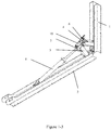
- Figure 2-1 is a schematic view of the installation structure of a folding and unfolding mechanism of the present invention
- Figure 2-2 is a schematic perspective view of a connecting structure of a four-connecting-rod of a folding and unfolding mechanism in the present invention
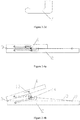
- Figures 2-3a to 2-3d are schematic structural views of four connecting rod of a folding and unfolding mechanism of the present invention
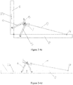
- Figures 2-4a to 2-4d are schematic views of specific applications of a folding and unfolding mechanism of the present invention.
- Figures 2-1, 2-2 , Figures 2-3a to 2-3d and Figures 2-4a to 2-4d show a folding and unfolding mechanism of a preferred embodiment, which is mounted between an upper panel 1 and a lower panel 2 which are hinged together, for folding and unfolding the upper panel 1 and the lower panel 2, and for overturning for 0-180 degrees between the upper panel 1 and the lower panel 2.
- the folding and unfolding mechanism comprises: a four-connecting-rod assembly, comprising a first connecting rod 4, a second connecting rod 5, a third connecting rod 6 and a fourth connecting rod 7, one end of the first connecting rod 4 being hinged to one end of the second connecting rod 5, the other end of the first connecting rod 4 being hinged to the upper panel 1, the other end of the second connecting rod 5 being hinged to the lower panel 2, and a first hinged joint 10 being formed at a hinged ends of the first connecting rod 4and the second connecting rod 5, the third connecting rod 6 being hinged to the first connecting rod 4 and the second connecting rod 5 through the first hinged joint 10, the third connecting rod 6 having a second hinged joint 11 at one end, one end of the fourth connecting rod 7 being hinged to the third connecting rod 6 through the second hinged joint 11;
- the folding and unfolding mechanism comprises: a pushrod assembly, comprising a pushrod 8 and a pushing portion 9, wherein one end of the pushrod 8 is connected to the other end of the fourth connecting rod 7, and the pushrod 8 is connected to the pushing portion 9 at the other end, the pushing portion 9 being mounted above the lower panel 2 to drive the pushrod 8 to move, and thus to drive the four-connecting-rod assembly to move, therefore achieving the technical effect of folding and unfolding;
- gaps are formed in opposite surfaces of the upper panel 1 and the lower panel 2, and accommodating space is formed, and the four-connecting-rod assembly is received in the accommodating space in a folded state.
- the mechanism structure is simplified and is concealed in the two panels without compromising the performance of folding and unfolding movements, thus occupying small space.
- the third connecting rod 6 is generally in the form of triangle, wherein two angles are provided with the first hinged joint 10 and the second hinged joint 11, respectively, and the third angle 13 is between the first convex edge 14 and the second convex edge 15 when the folding and unfolding mechanism is in a folded state, and abuts against the second convex edge 15 to push the upper panel 1 to perform pre-unfolding when the mechanism is unfolding, such that the triangular third connecting rod 6 is integrally formed into a jacking structure through two hinged joints and one top point, which can effectively solve the problem that the included angle between two connecting rods is so small that thus is insufficient; moreover, the third angle 13 of the third connecting rod is arc-shaped or is provided with a roller, so as to further enhance the effect of transitional auxiliary driving, but it is not limited to this.
- a rotating shaft 12 is running through the first hinged joint 10 for the hinge of the first connecting rod 4, the second connecting rod 5 and the third connecting rod 6, forming a structure of pivot connection.
- a corner damping (not shown in the figure) is disposed in the shaft 12 for buffering the panel when titled to a certain angle, so as to reduce the local impact on the supporting structure caused by the offset of the center of the gravity.
- another rotating shaft can also be arranged in the second hinged joint 11, and a corner damping is also disposed in the shaft for achieving the buffering effect.
- the pushing portion 9 is an electric cylinder, which is used as a power system to support stress and complete folding and unfolding of the panels, but the pushing portion 9 can also be an air cylinder and other power equipments, and can even be driven in a manual manner, but should not be limited to these.
- the fourth connecting rod 7 has a blind hole or a through-hole (not shown in the figure) at one end, one end of the pushrod 8 being running through the blind hole or the through-hole, and in this embodiment, the fourth connecting rod 7 is integrally formed into a L-shaped form to ensure the effectiveness in the direction of thrust during unfolding movement.
- one end of the upper panel 1 and one end of the lower panel 2 are hinged together by a hinge.
- both the upper panel and the lower panel are made of profiles having internal gaps in the structure, the folding and unfolding mechanism can be easily concealed in the gaps.
- the folding and unfolding mechanism can also be arranged on the side of the upper panel 1 and the lower panel 2; moreover, panels, all the hinged joints of the four-connecting-rod and convex edge structure are also arranged on the side of the upper panel land the lower panel 2, through which the technical effect having structure concealed can also be achieved.
- the fourth connecting rod 7 has a through-hole at the other end.
- One end of the pushrod 8 passes through the through-hole, and is hinged to the rotating shaft 12 running through the first hinged joint 10.
- the first hinged joint 10 extends outwards, forming a projection 14, and when the folding and unfolding mechanism is folding and unfolding, the projection 14 abuts against one side of the fourth connecting rod 4to limit a relative position of the third connecting rod 6 and the fourth connecting rod 7.
- the folding and unfolding mechanism is received in the upper and lower panels in a folded state.
- the mechanism structure is simplified and is concealed in the two panels without compromising the performance of folding and unfolding movements, thus occupying small space;
- the triangular third connecting rod 6 is integrally formed into a jacking structure through two hinged joints and one top point, which can effectively solve the problem that the included angle between two connecting rods is so small that thus is insufficient;
- a corner damping is disposed in the rotating shaft 12 for providing buffering when the panel is titled to a certain angle, so as to reduce the local impact on the supporting structure caused by the offset of the center of the gravity.
Landscapes
- Engineering & Computer Science (AREA)
- General Engineering & Computer Science (AREA)
- Mechanical Engineering (AREA)
- Pivots And Pivotal Connections (AREA)
Applications Claiming Priority (3)
| Application Number | Priority Date | Filing Date | Title |
|---|---|---|---|
| CN201620088860.XU CN205503734U (zh) | 2016-01-28 | 2016-01-28 | 一种折叠伸展机构 |
| CN201610061394.0A CN105545929B (zh) | 2016-01-28 | 2016-01-28 | 一种折叠伸展机构 |
| PCT/CN2017/072771 WO2017129140A1 (fr) | 2016-01-28 | 2017-01-26 | Mécanisme de déploiement pliable |
Publications (3)
| Publication Number | Publication Date |
|---|---|
| EP3409959A1 true EP3409959A1 (fr) | 2018-12-05 |
| EP3409959A4 EP3409959A4 (fr) | 2019-10-02 |
| EP3409959B1 EP3409959B1 (fr) | 2020-07-15 |
Family
ID=59398788
Family Applications (1)
| Application Number | Title | Priority Date | Filing Date |
|---|---|---|---|
| EP17743755.5A Not-in-force EP3409959B1 (fr) | 2016-01-28 | 2017-01-26 | Mécanisme de déploiement pliable |
Country Status (5)
| Country | Link |
|---|---|
| US (1) | US10337555B2 (fr) |
| EP (1) | EP3409959B1 (fr) |
| JP (1) | JP6608056B2 (fr) |
| AU (1) | AU2017211764A1 (fr) |
| WO (1) | WO2017129140A1 (fr) |
Families Citing this family (12)
| Publication number | Priority date | Publication date | Assignee | Title |
|---|---|---|---|---|
| US20150308491A1 (en) * | 2014-04-25 | 2015-10-29 | Teffy R. Chamoun | Lock mechanism |
| CN110905984A (zh) * | 2019-07-26 | 2020-03-24 | 上海邦邦机器人有限公司 | 一种新型四连杆结构 |
| CN110808446B (zh) * | 2019-12-02 | 2023-07-28 | 西南交通大学 | 一种板状天线折叠支架 |
| CN112003081B (zh) * | 2020-08-25 | 2021-08-24 | 北京安达维尔航空设备有限公司 | 一种设备助插拔固定机构 |
| CN112104776A (zh) * | 2020-10-13 | 2020-12-18 | 河北臻耀科技有限公司 | 游戏视野辅助装置 |
| CN113317298B (zh) * | 2020-11-12 | 2022-11-04 | 广东能达公路养护股份有限公司 | 一种应用于药水喷洒装置的同步展开机构 |
| CN112421204B (zh) * | 2020-12-02 | 2024-05-28 | 四川九洲电器集团有限责任公司 | 一种用于便携式设备天线收展的联动自锁结构 |
| CN112764470B (zh) * | 2021-02-24 | 2023-06-20 | 永城职业学院 | 一种稳定性高的计算机应用检测装置 |
| CN113952012B (zh) * | 2021-09-14 | 2024-04-26 | 漳州市第三医院(漳州市龙文医院) | 一种小转子骨块带袢钛板及其组件 |
| CN114259149B (zh) * | 2021-12-13 | 2024-01-26 | 陈根法 | 一种建筑工程用的智能型造价咨询装置 |
| CN117326103B (zh) * | 2023-11-10 | 2026-05-01 | 中科宇航技术股份有限公司 | 一种带有冗余备份的辅助脱拔装置及脱拔方法 |
| CN118943701B (zh) * | 2024-08-01 | 2025-07-11 | 哈尔滨工业大学 | 一种用于承载天线阵面的双侧多级同步折叠机构 |
Family Cites Families (24)
| Publication number | Priority date | Publication date | Assignee | Title |
|---|---|---|---|---|
| US3088727A (en) * | 1958-06-19 | 1963-05-07 | Magneti Marelli Spa | Control device of a window regulator in motor car doors |
| FR2512486A1 (fr) * | 1981-09-04 | 1983-03-11 | Renault | Dispositif d'equilibrage de hayon de vehicule automobile |
| CH696274A5 (de) * | 1995-04-04 | 2007-03-15 | Usm Holding Ag | Vorrichtung zum schwenkbaren Halten einer Flügelklappe. |
| JPH09177760A (ja) * | 1995-12-26 | 1997-07-11 | Energy Support Corp | リンク装置 |
| JP2000064335A (ja) * | 1998-08-17 | 2000-02-29 | Komatsu Ltd | アタッチメント取付装置 |
| ES2320086T3 (es) * | 2000-05-12 | 2009-05-19 | Antonio Giovannetti | Dispositivo accionado por resorte para el movimiento de una puerta, con un brazo de palanca ajustable del resorte. |
| US6618904B1 (en) * | 2000-09-25 | 2003-09-16 | Van-Rob Stampings Inc. | Spring loaded vehicle hinge mechanism |
| DE20100662U1 (de) * | 2001-01-15 | 2001-04-19 | Arturo Salice S.P.A., Novedrate, Como | Hebevorrichtung für eine zweiflügelige Faltklappe |
| US20070266912A1 (en) * | 2003-04-29 | 2007-11-22 | Swain Stephen C | Multi-Position Work Tables |
| ITMI20062232A1 (it) * | 2006-11-22 | 2008-05-23 | Agostino Ferrari Spa | Cerniera con ridotto ingombro per ante a movimento verticale |
| DE202007005957U1 (de) * | 2007-02-19 | 2008-06-26 | Liebherr-Hausgeräte Ochsenhausen GmbH | Kühl- und/oder Gefriergerät |
| AT506196B1 (de) * | 2007-12-19 | 2010-10-15 | Blum Gmbh Julius | Stellmechanismus zum bewegen einer hochbewegbaren klappe eines möbels |
| DE102008005463A1 (de) * | 2008-01-21 | 2009-07-23 | Huwil-Werke Gmbh Möbelschloss- Und Beschlagfabriken | Halteelement zum Verstellen eines Deckels eines Möbels |
| US8065966B1 (en) * | 2009-09-24 | 2011-11-29 | Bauer Products, Inc. | Odd link work surface lift |
| DE102011002117A1 (de) * | 2011-04-15 | 2012-10-18 | Horst Lautenschläger | Möbelscharnier |
| CN202108863U (zh) * | 2011-06-28 | 2012-01-11 | 三一重工股份有限公司 | 一种工程机械及其铰接伸展机构 |
| CN202326679U (zh) * | 2011-11-25 | 2012-07-11 | 宏碁股份有限公司 | 折叠式电子设备以及连杆式枢轴装置 |
| US8572808B2 (en) * | 2012-02-23 | 2013-11-05 | Sub-Zero, Inc. | Controlled closure system for a hinge |
| CN203255064U (zh) * | 2013-04-01 | 2013-10-30 | 深圳市凯卓立液压设备有限公司 | 一种可折叠汽车尾梯装置 |
| TWI530625B (zh) * | 2013-04-24 | 2016-04-21 | 宏碁股份有限公司 | 轉軸模組與電子裝置 |
| CN104029215B (zh) * | 2014-06-05 | 2015-12-02 | 哈尔滨工程大学 | 一种小型化水下液压机械手手臂关节结构 |
| CN205503734U (zh) * | 2016-01-28 | 2016-08-24 | 上海庆华蜂巢科技发展股份有限公司 | 一种折叠伸展机构 |
| CN105545929B (zh) * | 2016-01-28 | 2018-04-17 | 上海庆华蜂巢科技发展股份有限公司 | 一种折叠伸展机构 |
| CN106082047B (zh) * | 2016-08-17 | 2018-08-28 | 徐州海伦哲专用车辆股份有限公司 | 一种高空作业车工作平台调平装置 |
-
2017
- 2017-01-26 EP EP17743755.5A patent/EP3409959B1/fr not_active Not-in-force
- 2017-01-26 AU AU2017211764A patent/AU2017211764A1/en not_active Abandoned
- 2017-01-26 JP JP2018525455A patent/JP6608056B2/ja not_active Expired - Fee Related
- 2017-01-26 WO PCT/CN2017/072771 patent/WO2017129140A1/fr not_active Ceased
- 2017-01-26 US US15/775,925 patent/US10337555B2/en not_active Expired - Fee Related
Also Published As
| Publication number | Publication date |
|---|---|
| EP3409959B1 (fr) | 2020-07-15 |
| US20180328401A1 (en) | 2018-11-15 |
| JP6608056B2 (ja) | 2019-11-20 |
| JP2019501342A (ja) | 2019-01-17 |
| AU2017211764A1 (en) | 2018-05-31 |
| WO2017129140A1 (fr) | 2017-08-03 |
| US10337555B2 (en) | 2019-07-02 |
| EP3409959A4 (fr) | 2019-10-02 |
Similar Documents
| Publication | Publication Date | Title |
|---|---|---|
| EP3409959B1 (fr) | Mécanisme de déploiement pliable | |
| US11416039B2 (en) | Complex moving/rotating pivot shaft device | |
| JP5111506B2 (ja) | ヒンジ | |
| EP2778316B1 (fr) | Auvents rétractables | |
| CN102509739B (zh) | 一种太阳能电池帆板展开机构 | |
| CN108691363B (zh) | 折叠房屋 | |
| TWM453755U (zh) | 同步收展摺疊裝置 | |
| US20130081706A1 (en) | Air intake with double inlet door | |
| CN107914864B (zh) | 飞机机翼旋转收放机构及其收纳方法 | |
| JP6053908B2 (ja) | 揺動及び摺動運動でドアを移動させるための装置 | |
| JP6157332B2 (ja) | ダンパーヒンジ及びこのダンパーヒンジを用いた消火栓装置 | |
| EP4417826B1 (fr) | Mécanisme d'arbre rotatif et appareil électronique | |
| CN106640875B (zh) | 一种折叠伸展机构 | |
| WO2025201219A1 (fr) | Dispositif électronique | |
| CN112455652B (zh) | 一种多级伸缩缸结构及伸缩缸式折叠机翼 | |
| CN115853887B (zh) | 一种双超宽薄形平板的折叠和展开机构及其实现方法 | |
| CN112830432B (zh) | 一种高空作业平台 | |
| CN115627838A (zh) | 顶棚机器人 | |
| CN116398534A (zh) | 铰链机构和电子设备 | |
| TWM478992U (zh) | 雙軸同動雙包樞軸器 | |
| CN114043524A (zh) | 一种可折叠且能够锁止的机械臂 | |
| CN116729622B (zh) | 共轴折叠双桨机构及飞行器 | |
| CN214465361U (zh) | 一种新型折叠机构 | |
| CN217435438U (zh) | 一种具有爬行、滚动和飞行模态的机器人 | |
| KR20260065952A (ko) | 내측 폴딩형 플렉시블 스크린 모바일 단말 및 그 힌지 |
Legal Events
| Date | Code | Title | Description |
|---|---|---|---|
| STAA | Information on the status of an ep patent application or granted ep patent |
Free format text: STATUS: THE INTERNATIONAL PUBLICATION HAS BEEN MADE |
|
| PUAI | Public reference made under article 153(3) epc to a published international application that has entered the european phase |
Free format text: ORIGINAL CODE: 0009012 |
|
| STAA | Information on the status of an ep patent application or granted ep patent |
Free format text: STATUS: REQUEST FOR EXAMINATION WAS MADE |
|
| 17P | Request for examination filed |
Effective date: 20180507 |
|
| AK | Designated contracting states |
Kind code of ref document: A1 Designated state(s): AL AT BE BG CH CY CZ DE DK EE ES FI FR GB GR HR HU IE IS IT LI LT LU LV MC MK MT NL NO PL PT RO RS SE SI SK SM TR |
|
| AX | Request for extension of the european patent |
Extension state: BA ME |
|
| DAV | Request for validation of the european patent (deleted) | ||
| DAX | Request for extension of the european patent (deleted) | ||
| A4 | Supplementary search report drawn up and despatched |
Effective date: 20190903 |
|
| RIC1 | Information provided on ipc code assigned before grant |
Ipc: F16C 11/10 20060101ALI20190828BHEP Ipc: E05D 3/06 20060101ALI20190828BHEP Ipc: E05D 3/16 20060101ALI20190828BHEP Ipc: F16C 11/04 20060101AFI20190828BHEP |
|
| GRAC | Information related to communication of intention to grant a patent modified |
Free format text: ORIGINAL CODE: EPIDOSCIGR1 |
|
| STAA | Information on the status of an ep patent application or granted ep patent |
Free format text: STATUS: GRANT OF PATENT IS INTENDED |
|
| GRAP | Despatch of communication of intention to grant a patent |
Free format text: ORIGINAL CODE: EPIDOSNIGR1 |
|
| INTG | Intention to grant announced |
Effective date: 20200312 |
|
| GRAS | Grant fee paid |
Free format text: ORIGINAL CODE: EPIDOSNIGR3 |
|
| GRAA | (expected) grant |
Free format text: ORIGINAL CODE: 0009210 |
|
| STAA | Information on the status of an ep patent application or granted ep patent |
Free format text: STATUS: THE PATENT HAS BEEN GRANTED |
|
| AK | Designated contracting states |
Kind code of ref document: B1 Designated state(s): AL AT BE BG CH CY CZ DE DK EE ES FI FR GB GR HR HU IE IS IT LI LT LU LV MC MK MT NL NO PL PT RO RS SE SI SK SM TR |
|
| REG | Reference to a national code |
Ref country code: GB Ref legal event code: FG4D Ref country code: CH Ref legal event code: EP |
|
| REG | Reference to a national code |
Ref country code: DE Ref legal event code: R096 Ref document number: 602017019868 Country of ref document: DE |
|
| REG | Reference to a national code |
Ref country code: IE Ref legal event code: FG4D |
|
| REG | Reference to a national code |
Ref country code: AT Ref legal event code: REF Ref document number: 1291341 Country of ref document: AT Kind code of ref document: T Effective date: 20200815 |
|
| REG | Reference to a national code |
Ref country code: LT Ref legal event code: MG4D |
|
| REG | Reference to a national code |
Ref country code: AT Ref legal event code: MK05 Ref document number: 1291341 Country of ref document: AT Kind code of ref document: T Effective date: 20200715 |
|
| REG | Reference to a national code |
Ref country code: NL Ref legal event code: MP Effective date: 20200715 |
|
| PG25 | Lapsed in a contracting state [announced via postgrant information from national office to epo] |
Ref country code: HR Free format text: LAPSE BECAUSE OF FAILURE TO SUBMIT A TRANSLATION OF THE DESCRIPTION OR TO PAY THE FEE WITHIN THE PRESCRIBED TIME-LIMIT Effective date: 20200715 Ref country code: LT Free format text: LAPSE BECAUSE OF FAILURE TO SUBMIT A TRANSLATION OF THE DESCRIPTION OR TO PAY THE FEE WITHIN THE PRESCRIBED TIME-LIMIT Effective date: 20200715 Ref country code: BG Free format text: LAPSE BECAUSE OF FAILURE TO SUBMIT A TRANSLATION OF THE DESCRIPTION OR TO PAY THE FEE WITHIN THE PRESCRIBED TIME-LIMIT Effective date: 20201015 Ref country code: SE Free format text: LAPSE BECAUSE OF FAILURE TO SUBMIT A TRANSLATION OF THE DESCRIPTION OR TO PAY THE FEE WITHIN THE PRESCRIBED TIME-LIMIT Effective date: 20200715 Ref country code: ES Free format text: LAPSE BECAUSE OF FAILURE TO SUBMIT A TRANSLATION OF THE DESCRIPTION OR TO PAY THE FEE WITHIN THE PRESCRIBED TIME-LIMIT Effective date: 20200715 Ref country code: GR Free format text: LAPSE BECAUSE OF FAILURE TO SUBMIT A TRANSLATION OF THE DESCRIPTION OR TO PAY THE FEE WITHIN THE PRESCRIBED TIME-LIMIT Effective date: 20201016 Ref country code: NO Free format text: LAPSE BECAUSE OF FAILURE TO SUBMIT A TRANSLATION OF THE DESCRIPTION OR TO PAY THE FEE WITHIN THE PRESCRIBED TIME-LIMIT Effective date: 20201015 Ref country code: AT Free format text: LAPSE BECAUSE OF FAILURE TO SUBMIT A TRANSLATION OF THE DESCRIPTION OR TO PAY THE FEE WITHIN THE PRESCRIBED TIME-LIMIT Effective date: 20200715 Ref country code: PT Free format text: LAPSE BECAUSE OF FAILURE TO SUBMIT A TRANSLATION OF THE DESCRIPTION OR TO PAY THE FEE WITHIN THE PRESCRIBED TIME-LIMIT Effective date: 20201116 Ref country code: FI Free format text: LAPSE BECAUSE OF FAILURE TO SUBMIT A TRANSLATION OF THE DESCRIPTION OR TO PAY THE FEE WITHIN THE PRESCRIBED TIME-LIMIT Effective date: 20200715 |
|
| PG25 | Lapsed in a contracting state [announced via postgrant information from national office to epo] |
Ref country code: IS Free format text: LAPSE BECAUSE OF FAILURE TO SUBMIT A TRANSLATION OF THE DESCRIPTION OR TO PAY THE FEE WITHIN THE PRESCRIBED TIME-LIMIT Effective date: 20201115 Ref country code: LV Free format text: LAPSE BECAUSE OF FAILURE TO SUBMIT A TRANSLATION OF THE DESCRIPTION OR TO PAY THE FEE WITHIN THE PRESCRIBED TIME-LIMIT Effective date: 20200715 Ref country code: RS Free format text: LAPSE BECAUSE OF FAILURE TO SUBMIT A TRANSLATION OF THE DESCRIPTION OR TO PAY THE FEE WITHIN THE PRESCRIBED TIME-LIMIT Effective date: 20200715 Ref country code: PL Free format text: LAPSE BECAUSE OF FAILURE TO SUBMIT A TRANSLATION OF THE DESCRIPTION OR TO PAY THE FEE WITHIN THE PRESCRIBED TIME-LIMIT Effective date: 20200715 |
|
| PG25 | Lapsed in a contracting state [announced via postgrant information from national office to epo] |
Ref country code: NL Free format text: LAPSE BECAUSE OF FAILURE TO SUBMIT A TRANSLATION OF THE DESCRIPTION OR TO PAY THE FEE WITHIN THE PRESCRIBED TIME-LIMIT Effective date: 20200715 |
|
| REG | Reference to a national code |
Ref country code: DE Ref legal event code: R097 Ref document number: 602017019868 Country of ref document: DE |
|
| PG25 | Lapsed in a contracting state [announced via postgrant information from national office to epo] |
Ref country code: DK Free format text: LAPSE BECAUSE OF FAILURE TO SUBMIT A TRANSLATION OF THE DESCRIPTION OR TO PAY THE FEE WITHIN THE PRESCRIBED TIME-LIMIT Effective date: 20200715 Ref country code: CZ Free format text: LAPSE BECAUSE OF FAILURE TO SUBMIT A TRANSLATION OF THE DESCRIPTION OR TO PAY THE FEE WITHIN THE PRESCRIBED TIME-LIMIT Effective date: 20200715 Ref country code: RO Free format text: LAPSE BECAUSE OF FAILURE TO SUBMIT A TRANSLATION OF THE DESCRIPTION OR TO PAY THE FEE WITHIN THE PRESCRIBED TIME-LIMIT Effective date: 20200715 Ref country code: IT Free format text: LAPSE BECAUSE OF FAILURE TO SUBMIT A TRANSLATION OF THE DESCRIPTION OR TO PAY THE FEE WITHIN THE PRESCRIBED TIME-LIMIT Effective date: 20200715 Ref country code: EE Free format text: LAPSE BECAUSE OF FAILURE TO SUBMIT A TRANSLATION OF THE DESCRIPTION OR TO PAY THE FEE WITHIN THE PRESCRIBED TIME-LIMIT Effective date: 20200715 Ref country code: SM Free format text: LAPSE BECAUSE OF FAILURE TO SUBMIT A TRANSLATION OF THE DESCRIPTION OR TO PAY THE FEE WITHIN THE PRESCRIBED TIME-LIMIT Effective date: 20200715 |
|
| PLBE | No opposition filed within time limit |
Free format text: ORIGINAL CODE: 0009261 |
|
| STAA | Information on the status of an ep patent application or granted ep patent |
Free format text: STATUS: NO OPPOSITION FILED WITHIN TIME LIMIT |
|
| PG25 | Lapsed in a contracting state [announced via postgrant information from national office to epo] |
Ref country code: AL Free format text: LAPSE BECAUSE OF FAILURE TO SUBMIT A TRANSLATION OF THE DESCRIPTION OR TO PAY THE FEE WITHIN THE PRESCRIBED TIME-LIMIT Effective date: 20200715 |
|
| 26N | No opposition filed |
Effective date: 20210416 |
|
| PG25 | Lapsed in a contracting state [announced via postgrant information from national office to epo] |
Ref country code: SK Free format text: LAPSE BECAUSE OF FAILURE TO SUBMIT A TRANSLATION OF THE DESCRIPTION OR TO PAY THE FEE WITHIN THE PRESCRIBED TIME-LIMIT Effective date: 20200715 |
|
| REG | Reference to a national code |
Ref country code: DE Ref legal event code: R119 Ref document number: 602017019868 Country of ref document: DE |
|
| PG25 | Lapsed in a contracting state [announced via postgrant information from national office to epo] |
Ref country code: SI Free format text: LAPSE BECAUSE OF FAILURE TO SUBMIT A TRANSLATION OF THE DESCRIPTION OR TO PAY THE FEE WITHIN THE PRESCRIBED TIME-LIMIT Effective date: 20200715 Ref country code: MC Free format text: LAPSE BECAUSE OF FAILURE TO SUBMIT A TRANSLATION OF THE DESCRIPTION OR TO PAY THE FEE WITHIN THE PRESCRIBED TIME-LIMIT Effective date: 20200715 |
|
| REG | Reference to a national code |
Ref country code: CH Ref legal event code: PL |
|
| GBPC | Gb: european patent ceased through non-payment of renewal fee |
Effective date: 20210126 |
|
| PG25 | Lapsed in a contracting state [announced via postgrant information from national office to epo] |
Ref country code: LU Free format text: LAPSE BECAUSE OF NON-PAYMENT OF DUE FEES Effective date: 20210126 |
|
| REG | Reference to a national code |
Ref country code: BE Ref legal event code: MM Effective date: 20210131 |
|
| PG25 | Lapsed in a contracting state [announced via postgrant information from national office to epo] |
Ref country code: FR Free format text: LAPSE BECAUSE OF NON-PAYMENT OF DUE FEES Effective date: 20210131 |
|
| PG25 | Lapsed in a contracting state [announced via postgrant information from national office to epo] |
Ref country code: LI Free format text: LAPSE BECAUSE OF NON-PAYMENT OF DUE FEES Effective date: 20210131 Ref country code: GB Free format text: LAPSE BECAUSE OF NON-PAYMENT OF DUE FEES Effective date: 20210126 Ref country code: CH Free format text: LAPSE BECAUSE OF NON-PAYMENT OF DUE FEES Effective date: 20210131 Ref country code: DE Free format text: LAPSE BECAUSE OF NON-PAYMENT OF DUE FEES Effective date: 20210803 |
|
| PG25 | Lapsed in a contracting state [announced via postgrant information from national office to epo] |
Ref country code: IE Free format text: LAPSE BECAUSE OF NON-PAYMENT OF DUE FEES Effective date: 20210126 |
|
| PG25 | Lapsed in a contracting state [announced via postgrant information from national office to epo] |
Ref country code: IS Free format text: LAPSE BECAUSE OF FAILURE TO SUBMIT A TRANSLATION OF THE DESCRIPTION OR TO PAY THE FEE WITHIN THE PRESCRIBED TIME-LIMIT Effective date: 20201115 |
|
| PG25 | Lapsed in a contracting state [announced via postgrant information from national office to epo] |
Ref country code: BE Free format text: LAPSE BECAUSE OF NON-PAYMENT OF DUE FEES Effective date: 20210131 |
|
| PG25 | Lapsed in a contracting state [announced via postgrant information from national office to epo] |
Ref country code: CY Free format text: LAPSE BECAUSE OF FAILURE TO SUBMIT A TRANSLATION OF THE DESCRIPTION OR TO PAY THE FEE WITHIN THE PRESCRIBED TIME-LIMIT Effective date: 20200715 |
|
| PG25 | Lapsed in a contracting state [announced via postgrant information from national office to epo] |
Ref country code: HU Free format text: LAPSE BECAUSE OF FAILURE TO SUBMIT A TRANSLATION OF THE DESCRIPTION OR TO PAY THE FEE WITHIN THE PRESCRIBED TIME-LIMIT; INVALID AB INITIO Effective date: 20170126 |
|
| PG25 | Lapsed in a contracting state [announced via postgrant information from national office to epo] |
Ref country code: MK Free format text: LAPSE BECAUSE OF FAILURE TO SUBMIT A TRANSLATION OF THE DESCRIPTION OR TO PAY THE FEE WITHIN THE PRESCRIBED TIME-LIMIT Effective date: 20200715 |
|
| PG25 | Lapsed in a contracting state [announced via postgrant information from national office to epo] |
Ref country code: MT Free format text: LAPSE BECAUSE OF FAILURE TO SUBMIT A TRANSLATION OF THE DESCRIPTION OR TO PAY THE FEE WITHIN THE PRESCRIBED TIME-LIMIT Effective date: 20200715 |
|
| PG25 | Lapsed in a contracting state [announced via postgrant information from national office to epo] |
Ref country code: TR Free format text: LAPSE BECAUSE OF FAILURE TO SUBMIT A TRANSLATION OF THE DESCRIPTION OR TO PAY THE FEE WITHIN THE PRESCRIBED TIME-LIMIT Effective date: 20200715 |