EP3409984A1 - Kolbenschieberventil - Google Patents
Kolbenschieberventil Download PDFInfo
- Publication number
- EP3409984A1 EP3409984A1 EP18174671.0A EP18174671A EP3409984A1 EP 3409984 A1 EP3409984 A1 EP 3409984A1 EP 18174671 A EP18174671 A EP 18174671A EP 3409984 A1 EP3409984 A1 EP 3409984A1
- Authority
- EP
- European Patent Office
- Prior art keywords
- armature
- piston
- permanent magnet
- force
- valve
- Prior art date
- Legal status (The legal status is an assumption and is not a legal conclusion. Google has not performed a legal analysis and makes no representation as to the accuracy of the status listed.)
- Granted
Links
Images



Classifications
-
- F—MECHANICAL ENGINEERING; LIGHTING; HEATING; WEAPONS; BLASTING
- F16—ENGINEERING ELEMENTS AND UNITS; GENERAL MEASURES FOR PRODUCING AND MAINTAINING EFFECTIVE FUNCTIONING OF MACHINES OR INSTALLATIONS; THERMAL INSULATION IN GENERAL
- F16F—SPRINGS; SHOCK-ABSORBERS; MEANS FOR DAMPING VIBRATION
- F16F9/00—Springs, vibration-dampers, shock-absorbers, or similarly-constructed movement-dampers using a fluid or the equivalent as damping medium
- F16F9/32—Details
- F16F9/34—Special valve constructions; Shape or construction of throttling passages
-
- F—MECHANICAL ENGINEERING; LIGHTING; HEATING; WEAPONS; BLASTING
- F16—ENGINEERING ELEMENTS AND UNITS; GENERAL MEASURES FOR PRODUCING AND MAINTAINING EFFECTIVE FUNCTIONING OF MACHINES OR INSTALLATIONS; THERMAL INSULATION IN GENERAL
- F16K—VALVES; TAPS; COCKS; ACTUATING-FLOATS; DEVICES FOR VENTING OR AERATING
- F16K31/00—Actuating devices; Operating means; Releasing devices
- F16K31/02—Actuating devices; Operating means; Releasing devices electric; magnetic
- F16K31/06—Actuating devices; Operating means; Releasing devices electric; magnetic using a magnet, e.g. diaphragm valves, cutting off by means of a liquid
- F16K31/0644—One-way valve
- F16K31/0668—Sliding valves
-
- F—MECHANICAL ENGINEERING; LIGHTING; HEATING; WEAPONS; BLASTING
- F16—ENGINEERING ELEMENTS AND UNITS; GENERAL MEASURES FOR PRODUCING AND MAINTAINING EFFECTIVE FUNCTIONING OF MACHINES OR INSTALLATIONS; THERMAL INSULATION IN GENERAL
- F16K—VALVES; TAPS; COCKS; ACTUATING-FLOATS; DEVICES FOR VENTING OR AERATING
- F16K31/00—Actuating devices; Operating means; Releasing devices
- F16K31/02—Actuating devices; Operating means; Releasing devices electric; magnetic
- F16K31/06—Actuating devices; Operating means; Releasing devices electric; magnetic using a magnet, e.g. diaphragm valves, cutting off by means of a liquid
- F16K31/0675—Electromagnet aspects, e.g. electric supply therefor
-
- F—MECHANICAL ENGINEERING; LIGHTING; HEATING; WEAPONS; BLASTING
- F16—ENGINEERING ELEMENTS AND UNITS; GENERAL MEASURES FOR PRODUCING AND MAINTAINING EFFECTIVE FUNCTIONING OF MACHINES OR INSTALLATIONS; THERMAL INSULATION IN GENERAL
- F16K—VALVES; TAPS; COCKS; ACTUATING-FLOATS; DEVICES FOR VENTING OR AERATING
- F16K31/00—Actuating devices; Operating means; Releasing devices
- F16K31/02—Actuating devices; Operating means; Releasing devices electric; magnetic
- F16K31/06—Actuating devices; Operating means; Releasing devices electric; magnetic using a magnet, e.g. diaphragm valves, cutting off by means of a liquid
- F16K31/0686—Braking, pressure equilibration, shock absorbing
- F16K31/0693—Pressure equilibration of the armature
-
- F—MECHANICAL ENGINEERING; LIGHTING; HEATING; WEAPONS; BLASTING
- F16—ENGINEERING ELEMENTS AND UNITS; GENERAL MEASURES FOR PRODUCING AND MAINTAINING EFFECTIVE FUNCTIONING OF MACHINES OR INSTALLATIONS; THERMAL INSULATION IN GENERAL
- F16K—VALVES; TAPS; COCKS; ACTUATING-FLOATS; DEVICES FOR VENTING OR AERATING
- F16K31/00—Actuating devices; Operating means; Releasing devices
- F16K31/02—Actuating devices; Operating means; Releasing devices electric; magnetic
- F16K31/06—Actuating devices; Operating means; Releasing devices electric; magnetic using a magnet, e.g. diaphragm valves, cutting off by means of a liquid
- F16K31/08—Actuating devices; Operating means; Releasing devices electric; magnetic using a magnet, e.g. diaphragm valves, cutting off by means of a liquid using a permanent magnet
- F16K31/082—Actuating devices; Operating means; Releasing devices electric; magnetic using a magnet, e.g. diaphragm valves, cutting off by means of a liquid using a permanent magnet using a electromagnet and a permanent magnet
-
- F—MECHANICAL ENGINEERING; LIGHTING; HEATING; WEAPONS; BLASTING
- F16—ENGINEERING ELEMENTS AND UNITS; GENERAL MEASURES FOR PRODUCING AND MAINTAINING EFFECTIVE FUNCTIONING OF MACHINES OR INSTALLATIONS; THERMAL INSULATION IN GENERAL
- F16F—SPRINGS; SHOCK-ABSORBERS; MEANS FOR DAMPING VIBRATION
- F16F2230/00—Purpose; Design features
- F16F2230/24—Detecting or preventing malfunction, e.g. fail safe
Definitions
- the present invention relates to a spool valve, for example for a shock absorber of a vehicle.
- An electromagnetically operated spool valve may be used as a throttle valve in a hydraulic shock absorber of a vehicle to set a damper characteristic "hard” or “soft”.
- By means of the adjustable throttle valve can be changed depending on the energization of the excitation coil of the valve, the flow resistance of the valve and thereby the damping effect of the overall system.
- the valve connects two damper chambers, with pressure surges on the damper causing fluid displacement from one damper chamber into the other damper chamber.
- the valve may be normally closed (NC) or open (normally open, NO) when de-energized.
- N normally closed
- NO normally open
- the valve assumes a predetermined position in the de-energized state, this is also referred to as fail-safe state, since the valve assumes this state when switching off or a failure of the entire system, for example in the event of a power failure.
- This fail-safe function is used, for example, in motor vehicle shock absorbers. It may be advantageous if the fail-safe state defines a partially open state of the valve, so that in the event of a system failure, the damper does not change to a very soft or hard identifier in order to ensure a moderate and safe driving condition.
- Electromagnetically actuated NO valves are known. These valves have a fail-safe position, in which the valve is partially open, ie a position in the non-energized state between the maximum open and closed position. If the coil of the valve is energized electrically, the piston (also referred to as a slide) of the valve initially moves to the maximum open position and can be held there with a Grundbestromung, ie a minimum current, which is necessary to keep the valve open , As the current continues to increase, the slider moves continuously toward the closed position.
- a fail-safe position in which the valve is partially open, ie a position in the non-energized state between the maximum open and closed position. If the coil of the valve is energized electrically, the piston (also referred to as a slide) of the valve initially moves to the maximum open position and can be held there with a Grundbestromung, ie a minimum current, which is necessary to keep the valve open , As the current continues to increase, the slider moves continuously toward the closed position.
- valves have two armature and two corresponding biasing springs.
- a minimum magnetic force is needed, and in the case of a "basic energization" it is necessary to reduce the force of the fail-safe spring, i. to overcome that spring which urges the piston towards the fail-safe position.
- the valve switches to the fail-safe state. A lowering of the Grundbestromung is therefore not possible.
- Even external influences, such as vibrations due to road bumps, can also cause the valve unintentionally changes from the maximum open position to the fail-safe position at Grundergromung.
- the fail-safe spring can not be arbitrarily stiff and thus the fail-safe hub can not be made arbitrarily large, otherwise the valve would easily switch to the fail-safe state.
- a stiff fail-safe spring requires a high base current to overcome the biasing force of the fail-safe spring and to hold the maximum open position of the valve.
- the object of the invention is therefore to provide an electromagnetically operated spool valve having a fail-safe function with low electrical Grundbestromung, large fail-safe stroke of the valve and stability against external interference.
- a spool valve comprises a spool valve assembly having a piston which is axially displaceable for regulating a free cross-sectional area of a fluid passage between a first fluid port and a second fluid port of the valve in a valve housing.
- the spool assembly further includes a first armature connected to the piston and a second armature axially displaceable relative to the piston, and a first biasing means and a second biasing means.
- the first and second pretensioners may be in particular each act on a biasing spring.
- the first armature is connected to the piston, ie it moves axially together with the piston. In particular, the connection may be referred to as "fixed” or "stationary", wherein the first armature and the piston need not necessarily be inseparably connected.
- the piston By generating an electromagnetic field by energizing a coil, the piston is axially displaceable against the force of the first biasing means.
- the second pretensioning device is supported against the first magnet armature and the second magnet armature, so that the piston assumes a predetermined position in the non-energized state of the coil by axially displacing due to the force of the second pretensioning device against the force of the first pretensioning device.
- the predetermined position defines the initially explained fail-safe position of the valve and is taken in particular at the transition from the energized state to the de-energized state of the valve, i. especially when switching off the valve or in the event of a system failure.
- the piston valve according to the invention can be used in a shock absorber for a motor vehicle.
- the spool valve further comprises a permanent magnet acting on at least one of the first armature armature and the second armature such that a magnetic force caused by the permanent magnet counteracts the force of the second pretensioner.
- the magnetic force acts in particular in an energized state of the valve, in which the current is greater than or equal to a Grundbestromung. If the term "magnet” is used in the following description, the permanent magnet is meant. If the electromagnet, that is, in particular the coil, of the valve should be meant, this is clearly clarified.
- the Grundbestromung defines the minimum current that is necessary to overcome the force of the second biasing means and, for example, to hold a maximum open position of the valve.
- the permanent magnet By providing a permanent magnet, which counteracts the force of the second biasing means, the disadvantages described above can be overcome.
- the permanent magnet allows a lower electrical Grundbestromung the valve, since it supports the achieved by the Grundbestromung of the valve position, eg the maximum open position, ie helping to hold this position, without the valve unintentionally back into the fail-safe Position changes.
- a significantly reduced energy consumption can be achieved because in a vehicle several valves, for example, up to eight valves, can be installed.
- a harder fail-safe vote possible ie a larger fail-safe stroke of the slide or piston.
- the piston valve according to the invention has an increased robustness in the position reached by the Grundbestromung valve position against interference, eg mechanical excitation of the valve from the outside or flow forces on. Overall, this can increase the control range of the valve can be achieved with better resolution.
- the permanent magnet is arranged such that the magnetic force caused by the permanent magnet moves the first armature and the second armature towards each other.
- the permanent magnet may be arranged to exert an attractive force between the first armature and the second armature.
- this may be the case when the second biasing means is arranged such that it presses apart the first armature and the second armature.
- the magnetic force of the permanent magnet supports the holding force between the first and second armature.
- the described effect of the magnetic force generally relates in particular to a state of the valve in which at least the base current is applied.
- the magnetic force is described for a state of the valve in which the first armature and the second armature are arranged sufficiently close to each other, in particular directly adjacent to each other and touch if necessary.
- This position of the valve is achieved in particular by applying the Grundbestromung, which overcomes the force of the second biasing means, that is, in particular the fail-safe spring, which is supported against the first and second armature.
- first armature and the second armature in the non-energized state of the valve may be too far apart, so that the permanent magnet no relevant force between the first armature and the second armature, that is, in particular, no or only a very small force, which counteracts the force of the second biasing means can unfold.
- the permanent magnet may in particular be arranged between the first magnet armature and the second magnet armature.
- the permanent magnet is advantageously arranged in at least one of the first magnet armature and the second armature armature.
- the magnet can be arranged in the first magnet armature.
- the magnet may alternatively be arranged in the second armature.
- at least one permanent magnet is provided both in the first and in the second armature. These can be arranged, for example offset in the radial direction to one another, or axially aligned with respect to the direction of the magnetization, so that a force is achieved by the permanent magnets, which counteracts the force of the second biasing means.
- the permanent magnet may for example be used or embedded in the corresponding magnet armature, for example, mounted as a separate component or injected by injection molding.
- the arrangement of the magnet in the armature the size of the valve remains unchanged and there is no additional space required.
- Another advantage of the positioning of the magnet in the armature is that when arranged in the magnet armature - and thus on a small diameter - already relatively little permanent magnet volume sufficient to raise the holding force significantly.
- the arrangement of the magnet in one of the armature closes around the magnet an iron circle over both anchors.
- Positioning elsewhere in the iron circle eg in a transition disk
- the force of the first biasing spring would have to be increased accordingly.
- the fail-safe spring force would have to rise in the same turn. The gain in holding power would thus be compensated.
- the permanent magnet is disposed in at least one of the first armature and the second armature near a surface facing the other one of the first and second armature.
- the magnet can be inserted into the corresponding magnet armature, for example inserted into a recess in the surface of the magnet armature.
- the permanent magnet is embedded near the surface in the corresponding armature, so that the magnet is completely enclosed by the material of the magnet armature.
- the complete embedding of the permanent magnet impedes the expression of the magnetic flux at the contact surface of the two armature. Therefore, the permanent magnet is preferably at least partially exposed.
- the permanent magnet is magnetized substantially in the axial direction, so that it can optimally counteract an axial force of the second biasing device.
- the permanent magnet is preferably magnetized in a direction parallel to the force of the second biasing means.
- the magnetic force caused by the permanent magnet is weaker than the force of the second biasing means, so that the force of the second biasing means in the non-energized state of the valve outweighs the magnetic force and the piston, the predetermined position, that is, the valve is the fail-safe position occupy can.
- the magnetic force of the permanent magnet is sufficiently large, as explained, to support the position of the valve in Grundbestromung.
- the permanent magnet may be formed as a ring magnet or comprise at least one ring magnet. It is understood that other forms of the magnet are conceivable, for example ring magnet segments, or other non-annular elements.
- the permanent magnet may be formed in one piece or comprise several parts. For example, a plurality of individual magnets around the longitudinal axis of Magnet armature be arranged around, in particular arranged regularly. The individual magnets can have any suitable shapes.
- a step or recess may be provided on one end side of the first or second magnet armature, which upon energizing the valve to a corresponding end side of the corresponding other of the first and second magnet armature borders.
- a known spool valve 1 is shown in section to briefly explain the basic operation.
- the valve 1 In the in Fig. 1 shown de-energized state, the valve 1 is opened, ie it is a spool valve 1 in NO construction ("normally open").
- the valve 1 has a valve housing 2 with a first fluid port 3, which depending on the application may be a fluid inlet, and a second fluid port 4, which may be a fluid outlet depending on the application.
- the fluid inlet 3 is arranged axially and the fluid outlet 4 comprises a plurality of radial openings.
- a slide is for example off EP 1 538 366 A1 known. It should be understood that the present invention is not limited to such a spool assembly, but that other spool or piston designs may be used to control a free cross-section of a fluid passage.
- the piston 5 is connected to a magnet armature 7, so that the piston 5 and the magnet armature 7 move together.
- the armature 7 - and thus the piston 5 - is axially displaceable by means of the magnetic field generated by a coil 8.
- a magnetic force acts in a closed magnetic circuit, and the piston 5 is thereby moved against the force of a biasing spring 9 in the direction of a stationary pole member 17.
- the biasing spring 9 which may also be referred to as a control spring, is supported on the valve housing 2 and the piston 5 and urges the piston 5 in the embodiment shown here in a position in which the fluid passage 6 is open to the maximum.
- the fluid passage 6 in the non-energized state of the spool 8 of the valve 1, the fluid passage 6 is maximally opened, that is, the valve 1 is normally open (NO).
- the piston 5 could be urged by means of the biasing spring 9 in a position in which the fluid passage 6 is closed (normally closed, NC).
- Fig. 2A and 2 B show a spool valve 1 ', which in principle similar to the in Fig. 1 shown piston valve 1 is constructed, and therefore the same reference numerals are used for corresponding parts. However, this points in Fig. 2A and 2 B shown piston valve 1 'on a so-called fail-safe function.
- the valve 1 assumes a position in a non-energized state, in which the fluid passage 6 is neither open nor fully closed, but partially open.
- a damping characteristic is thereby achieved which is neither very hard nor completely soft, so that the vehicle has a moderate damping characteristic, for example in the event of a system failure.
- the fail-safe function is achieved by a division of the magnetic armature and by providing a second bias spring in addition to the control spring 9.
- the second biasing spring 10 is disposed between the first armature 11, which may be referred to as a control armature, and the second armature 12, which may be referred to as a fail-safe armature, and pushes the two armatures 11, 12 apart.
- the first armature 11 is fixedly connected to a piston rod 13 of the piston 5, whereas the second armature 12 is axially displaceable on the piston rod 13.
- the force of the second biasing spring 10 counteracts the force of the first biasing spring 9 until an equilibrium of forces is reached and the valve 1 'so that in Fig. 2A shown partially open position occupies.
- the force of the second biasing spring 10 is overcome by an electromagnetic attraction between the two armatures 11, 12 from reaching a Grundbestromung, so that the two armature 11, 12 abut each other frontally.
- the fluid passage 6 is open at maximum, as in Fig. 2B shown.
- the first armature 11 and the second armature 12 move as a unit against the force of the first biasing spring 9, and the valve 1 'is closed (not shown).
- the second biasing spring 10 pushes the first and second armature 11, 12 against the force of the first biasing spring 9 apart again, so that the valve in Fig. 2A shown position, ie the fail-safe position occupies.
- the valve 1 should not fall unintentionally in the fail-safe position, for example due to vibrations in road bumps. Therefore, a sufficient base current is required to the in Fig. 2B hold position shown. That is, sufficient electromagnetic force must be generated to overcome the force of the second biasing spring 10 and to achieve sufficient excess force, ie, holding force between the first and second armature 11, 12.
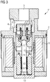
- FIG. 3 1 shows a piston slide valve 1 "according to the invention
- Fig. 3 illustrated position of the valve 1 correlates to in Fig. 2B illustrated position of the valve 1 '.
- the description goes to Fig. 2B referenced and for corresponding parts, the same reference numerals are used.
- Fig. 3 illustrated inventive valve 1 on a permanent magnet 14, which contributes to the in Fig. 3
- the permanent magnet 14 is arranged between the first magnet armature 11 and the second magnet armature 12 in order to generate an attractive force between the first and second armature 11, 12, that of the force of the second biasing spring 10 counteracts.
- the permanent magnet 14 is disposed in the first armature 11.
- the permanent magnet 14 may be formed as a ring magnet, which is inserted in a corresponding annular recess 15 on an end face 16 of the first armature 11 (see also Fig. 4 ).
- the permanent magnet 14 may have any other shapes and be inserted or embedded in the armature 11.
- the arrangement of the permanent magnet within the armature 11 has several advantages. On the one hand, an iron circle closes over both magnet armatures 11, 12, so that the magnet 14 only increases the attractive force between the two magnet armatures 11, 12, but does not engage in the electromagnetic circuit and, for example, also increases the attraction force to the pole part 17. This would disadvantageously require a stronger control spring 9 and thus a higher base current to reach the maximum open position of the valve.
- the attraction force generated by the permanent magnet 14 between the first and second armature 11, 12 counteracts the force of the second biasing spring 10 and increases the holding force generated by the Grundbestromung between the first armature 11 and the second armature 12.
- the holding for the maximum open position of the valve 1 "necessary Grundbestromung can therefore in comparison to a valve without the permanent magnet 14 (for example, the in Fig. 2A and 2 B shown valve 1 ') can be reduced.
- FIG. 4 shown detail of the valve 1 "from Fig. 3 is another measure recognizable, which can improve the holding force between the first armature 11 and the second armature 12.
- the first magnet armature 11 has a flat step 18 on its end face 16 which points in the direction of the second magnet armature 12.
- the end face 16 of the first magnet armature has a slightly recessed area 19, which in particular can be a radially inner area.
- the magnetic flux concentrates on a small contact surface 20, so that there increases the magnetic flux density, which in turn generates an increased holding force between the two armatures 11, 12.
- This measure can additionally be provided for arranging a permanent magnet.
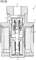
- Fig. 5 shows approximately the course of the magnetic field lines around the permanent magnet 14 between the two armatures 11, 12 when energized coil.
- the permanent magnet 14 is magnetized in the axial direction to improve the holding force between the first and second armature 11, 12 and optimally counteract the force of the second biasing spring 10.
- the largest magnetic flux density between the two armature is shown at the contact surface of the two armature (see. Fig. 4 ).
Landscapes
- Engineering & Computer Science (AREA)
- General Engineering & Computer Science (AREA)
- Mechanical Engineering (AREA)
- Physics & Mathematics (AREA)
- Electromagnetism (AREA)
- Magnetically Actuated Valves (AREA)
- Power Engineering (AREA)
Abstract
Description
- Die vorliegende Erfindung betrifft ein Kolbenschieberventil, beispielsweise für einen Stoßdämpfer eines Fahrzeugs.
- Ein elektromagnetisch betätigtes Kolbenschieberventil kann als Drosselventil in einem hydraulischen Stoßdämpfer eines Fahrzeugs eingesetzt werden, um eine Dämpfercharakteristik "hart" oder "weich" einzustellen. Mittels des verstellbaren Drosselventils kann je nach Bestromung der Erregerspule des Ventils der Strömungswiderstand des Ventils und dadurch die Dämpfungswirkung des Gesamtsystems verändert werden. Das Ventil verbindet dabei zwei Dämpferkammern, wobei Druckstöße am Dämpfer eine Fluidverdrängung aus einer Dämpferkammer in die andere Dämpferkammer verursachen.
- Abhängig von der Anwendung kann es erforderlich sein, dass das Ventil im stromlosen Zustand geschlossen ("normal closed", NC) oder offen ("normal open", NO) ist. Wenn das Ventil im stromlosen Zustand eine vorgegebene Position einnimmt, wird dies auch als Fail-Safe-Zustand bezeichnet, da das Ventil diesen Zustand beim Abschalten oder einem Ausfall des Gesamtsystems, beispielsweise bei einem Ausfall der Stromversorgung, einnimmt. Diese Fail-Safe-Funktion kommt zum Beispiel bei Kraftfahrzeugstoßdämpfern zum Einsatz. Es kann vorteilhaft sein, wenn der Fail-Safe-Zustand einen teilweise geöffneten Zustand des Ventils definiert, so dass bei einem Systemausfall der Dämpfer nicht in eine ganz weiche oder harte Kennung wechselt, um damit einen gemäßigten und sicheren Fahrzustand sicherzustellen.
- Aus der
DE 10 2008 035 899 A1 und derDE 10 2013 106 214 A1 sind elektromagnetisch betätigte NO-Ventile bekannt. Diese Ventile weise eine Fail-Safe-Stellung auf, in der das Ventil teilweise geöffnet ist, d.h. eine Stellung im nicht bestromten Zustand zwischen der maximal geöffneten und geschlossenen Stellung. Wird die Spule des Ventils elektrisch bestromt, bewegt sich der Kolben (auch als Schieber bezeichnet) des Ventils zunächst in die maximal geöffnete Stellung und kann dort mit einer Grundbestromung gehalten werden, d.h. einer Minimalbestromung, die nötig ist, um das Ventil maximal offen zu halten. Bei weiterer Erhöhung des Stroms bewegt sich der Schieber kontinuierlich in Richtung der geschlossenen Stellung. - Diese Ventile weisen zwei Magnetanker und zwei entsprechende Vorspannfedern auf. Um das Ventil in der maximal geöffneten Stellung zu halten, ist eine Mindestmagnetkraft und bei einer "Grundbestromung" notwendig, um die Kraft der Fail-Safe-Feder, d.h. derjenigen Feder, die den Kolben in Richtung der Fail-Safe-Stellung drängt, zu überwinden. Bei einem Absenken der Bestromung unter die Grundbestromung schaltet das Ventil in den Fail-Safe-Zustand. Ein Absenken der Grundbestromung ist somit nicht möglich. Auch äußere Einflüsse, wie beispielsweise Vibrationen aufgrund von Fahrbahnunebenheiten, können ebenfalls dazu führen, dass das Ventil bei Grundbestromung ungewollt von der maximal geöffneten Stellung in die Fail-Safe-Stellung wechselt. Darüber hinaus kann die Fail-Safe-Feder nicht beliebig steif und damit der Fail-Safe-Hub nicht beliebig groß gestaltet werden, da das Ventil sonst zu leicht in den Fail-Safe-Zustand wechseln würde. Anders ausgedrückt erfordert eine steife Fail-Safe-Feder eine hohe Grundbestromung zum Überwinden der Vorspannkraft der Fail-Safe-Feder und zum Halten der maximal geöffneten Stellung des Ventils.
- Aufgabe der Erfindung ist es daher, ein elektromagnetisch betätigtes Kolbenschieberventil bereitzustellen, das eine Fail-Safe-Funktion bei geringer elektrischer Grundbestromung, großem Fail-Safe-Hub des Ventils und Stabilität gegenüber äußeren Störeinflüssen aufweist.
- Die Aufgabe wird gelöst durch ein elektromagnetisch betätigtes Kolbenschieberventil mit den Merkmalen des unabhängigen Anspruchs 1. Bevorzugte Ausgestaltungen und Weiterbildungen sind in den abhängigen Ansprüchen angegeben.
- Ein Kolbenschieberventil gemäß der Erfindung umfasst eine Kolbenschieberanordnung mit einem Kolben, der zum Regeln einer freien Querschnittsfläche eines Fluiddurchgangs zwischen einem ersten Fluidanschluss und einem zweiten Fluidanschluss des Ventils in einem Ventilgehäuse axial verschieblich ist. Die Kolbenschieberanordnung umfasst des Weiteren einen ersten, mit dem Kolben verbundenen Magnetanker und einen zweiten, bezüglich des Kolbens axial verlagerbaren Magnetanker, sowie eine erste Vorspanneinrichtung und eine zweite Vorspanneinrichtung. Bei der ersten und zweiten Vorspanneinrichtung kann es sich insbesondere jeweils um eine Vorspannfeder handeln. Der erste Magnetanker ist mit dem Kolben verbunden, d.h. er bewegt sich axial zusammen mit dem Kolben. Insbesondere kann die Verbindung als "fest" oder "ortsfest" bezeichnet werden, wobei der erste Magnetanker und der Kolben nicht notwendigerweise untrennbar verbunden sein müssen.
- Durch Erzeugen eines elektromagnetischen Felds durch Bestromen einer Spule ist der Kolben entgegen der Kraft der ersten Vorspanneinrichtung axial verlagerbar. Gleichzeitig stützt sich die zweite Vorspanneinrichtung gegen den ersten Magnetanker und den zweiten Magnetanker ab, so dass der Kolben im nicht bestromten Zustand der Spule durch axiales Verlagern aufgrund der Kraft der zweiten Vorspanneinrichtung entgegen der Kraft der ersten Vorspanneinrichtung eine vorgegebene Position einnimmt. Die vorgegebene Position definiert die eingangs erläuterte Fail-Safe-Stellung des Ventils und wird insbesondere beim Übergang vom bestromten Zustand zum unbestromten Zustand des Ventils eingenommen, d.h. insbesondere beim Abschalten des Ventils oder bei einem Systemausfall. Vorteilhaft kann das erfindungsgemäße Kolbenschieberventil in einem Stoßdämpfer für ein Kraftfahrzeug eingesetzt werden.
- Erfindungsgemäß umfasst das Kolbenschieberventil des Weiteren einen Permanentmagneten, der derart auf zumindest einen des ersten Magnettankers und des zweiten Magnetankers wirkt, dass eine durch den Permanentmagneten verursachte Magnetkraft der Kraft der zweiten Vorspanneinrichtung entgegenwirkt. Die Magnetkraft wirkt insbesondere in einem bestromten Zustand des Ventils, in dem die Stromstärke größer oder gleich einer Grundbestromung ist. Falls in der folgenden Beschreibung der Begriff "Magnet" verwendet wird, ist der Permanentmagnet gemeint. Falls der Elektromagnet, das heißt insbesondere die Spule, des Ventils gemeint sein soll, wird dies eindeutig klargestellt. Die Grundbestromung definiert die Mindeststromstärke, die zum Überwinden der Kraft der zweiten Vorspanneinrichtung und beispielsweise zum Halten einer maximal geöffneten Stellung des Ventils notwendig ist.
- Durch Vorsehen eines Permanentmagneten, der der Kraft der zweiten Vorspanneinrichtung entgegenwirkt, können die eingangs beschriebenen Nachteile überwunden werden. Insbesondere ermöglicht der Permanentmagnet eine niedrigere elektrische Grundbestromung des Ventils, da er die durch die Grundbestromung des Ventils erreichte Stellung, z.B. die maximal geöffnete Stellung, unterstützt, d.h. dazu beiträgt, diese Stellung zu halten, ohne dass das Ventil ungewollt zurück in die Fail-Safe-Stellung wechselt. Dadurch kann ein erheblich reduzierter Energieverbrauch erreicht werden, da in einem Fahrzeug mehrere Ventile, beispielsweise bis zu acht Ventile, verbaut sein können. Zudem wird eine härtere Fail-Safe-Abstimmung möglich, d.h. ein größerer Fail-Safe-Hub des Schiebers bzw. Kolbens. Das erfindungsgemäße Kolbenschieberventil weist eine erhöhte Robustheit in der durch die Grundbestromung erreichten Stellung des Ventils gegen Störeinflüsse, z.B. mechanische Anregung des Ventils von außen oder Strömungskräfte, auf. Insgesamt kann dadurch eine Vergrößerung des Regelbereichs des Ventils mit besserer Auflösung erreicht werden.
- Vorzugsweise ist der Permanentmagnet derart angeordnet, dass die durch den Permanentmagneten verursachte Magnetkraft den ersten Magnetanker und den zweiten Magnetanker aufeinander zu bewegt. Insbesondere kann der Permanentmagnet derart angeordnet sein, dass er eine Anziehungskraft zwischen dem ersten Magnetanker und dem zweiten Magnetanker ausübt. Insbesondere kann dies der Fall sein, wenn die zweite Vorspanneinrichtung derart angeordnet ist, dass sie den ersten Magnetanker und den zweiten Magnetanker auseinander drückt. Die Magnetkraft des Permanentmagneten unterstützt die Haltekraft zwischen dem ersten und zweiten Magnetanker.
- Wie bereits kurz angedeutet, bezieht sich die beschriebene Wirkung der Magnetkraft generell insbesondere auf einen Zustand des Ventils, in welchem mindestens die Grundbestromung anliegt. Mit anderen Worten wird die Magnetkraft für einen Zustand des Ventils beschrieben, in welchem der erste Magnetanker und der zweite Magnetanker ausreichend nahe zueinander angeordnet sind, insbesondere direkt aneinander angrenzen und sich gegebenenfalls berühren. Diese Stellung des Ventils wird insbesondere durch Anlegen der Grundbestromung erreicht, welche die Kraft der zweiten Vorspanneinrichtung, das heißt insbesondere der Fail-Safe-Feder, welche sich gegen den ersten und zweiten Magnetanker abstützt, überwindet. Dagegen sind der erste Magnetanker und der zweite Magnetanker im nicht bestromten Zustand des Ventils möglicherweise zu weit voneinander entfernt, so dass der Permanentmagnet keine relevante Kraft zwischen dem ersten Magnetanker und dem zweiten Magnetanker, das heißt insbesondere keine oder nur eine sehr geringe Kraft, die der Kraft der zweiten Vorspanneinrichtung entgegenwirkt, entfalten kann.
- Der Permanentmagnet kann insbesondere zwischen dem ersten Magnetanker und dem zweiten Magnetanker angeordnet sein. Vorteilhaft ist der Permanentmagnet in zumindest einem des ersten Magnetankers und des zweiten Magnetankers, angeordnet. Beispielsweise kann der Magnet im ersten Magnetanker angeordnet sein. Es versteht sich, dass der Magnet alternativ auch im zweiten Magnetanker angeordnet sein kann. Denkbar ist auch, dass sowohl im ersten als auch im zweiten Magnetanker zumindest ein Permanentmagnet vorgesehen ist. Diese können beispielsweise in radialer Richtung versetzt zueinander angeordnet sein, oder axial zueinander ausgerichtet unter Berücksichtigung der Richtung der Magnetisierung, so dass durch die Permanentmagneten eine Kraft erreicht wird, die der Kraft der zweiten Vorspanneinrichtung entgegenwirkt.
- Der Permanentmagnet kann in dem entsprechenden Magnetanker beispielsweise eingesetzt oder eingebettet sein, beispielsweise als separates Bauteil montiert oder im Spritzgussverfahren mit eingespritzt. Durch die Anordnung des Magneten in dem Magnetanker bleibt die Baugröße des Ventils unverändert und es ist kein zusätzlicher Bauraum notwendig. Ein weiterer Vorteil der Positionierung des Magneten im Magnetanker besteht darin, dass bei Anordnung im Magnetanker - und damit auf kleinem Durchmesser - bereits relativ wenig Dauermagnetvolumen ausreicht, um die Haltekraft signifikant anzuheben.
- Durch die Anordnung des Magneten in einem der Magnetanker (oder gegebenenfalls in beiden Magentankern) schließt sich um den Magneten ein Eisenkreis über beide Anker. Somit ist gewährleistet, dass der Magnet nur zu einer Erhöhung der Anziehungskraft zwischen den Ankern beiträgt. Eine Positionierung an anderer Stelle im Eisenkreis (z.B. in einer Übertrittscheibe) hätte einen magnetgetriebenen Fluss zur Folge, der neben dem Spalt zwischen beiden Magnetankern auch den Arbeitsluftspalt zwischen dem ersten Magnetanker und einem ortsfesten Polteil passiert. Damit würde neben der Haltekraft zwischen den Magnetankern auch die Magnetkraft im Regelbetrieb steigen. Die Kraft der ersten Vorspannfeder müsste entsprechend erhöht werden. Um den Fail-Safe-Hub dabei nicht zu reduzieren, müsste im gleichen Zug auch die Fail-Safe-Federkraft steigen. Der Zugewinn an Haltekraft wäre damit kompensiert.
- Vorteilhaft ist der Permanentmagnet in zumindest einem des ersten Magnetankers und des zweiten Magnetankers nahe einer Oberfläche, die dem entsprechend anderen des ersten und zweiten Magnetankers zugewandt ist, angeordnet. Wie erwähnt kann der Magnet in den entsprechenden Magnetanker eingesetzt sein, beispielsweise in eine Ausnehmung in der Oberfläche des Magnetankers eingesetzt sein. Theoretisch denkbar wäre, dass der Permanentmagnet nahe der Oberfläche in den entsprechenden Magnetanker eingebettet ist, so dass der Magnet vollständig von dem Material des Magnetankers umschlossen ist. Jedoch behindert die vollständige Einbettung des Permanentmagneten die Ausprägung des Magnetflusses an der Kontaktfläche der beiden Magnetanker. Daher liegt der Permanentmagnet vorzugsweise zumindest teilweise frei.
- Vorteilhaft ist der Permanentmagnet im Wesentlichen in axialer Richtung magnetisiert, so dass er einer axialen Kraft der zweiten Vorspanneinrichtung optimal entgegenwirken kann. Mit anderen Worten ist der Permanentmagnet vorzugsweise in einer Richtung parallel zur Kraft der zweiten Vorspanneinrichtung magnetisiert. Vorzugsweise ist die durch den Permanentmagneten verursachte Magnetkraft schwächer als die Kraft der zweiten Vorspanneinrichtung, damit die Kraft der zweiten Vorspanneinrichtung im nicht bestromten Zustand des Ventils die Magnetkraft überwiegt und der Kolben die vorgegebene Position, das heißt das Ventil die Fail-Safe-Stellung, einnehmen kann. Die Magnetkraft des Permanentmagneten ist jedoch ausreichend groß, um wie erläutert die Stellung des Ventils bei Grundbestromung zu unterstützen.
- Der Permanentmagnet kann als Ringmagnet ausgebildet sein oder zumindest einen Ringmagnet umfassen. Es versteht sich, dass auch andere Formen des Magneten denkbar sind, z.B. Ringmagnetsegmente, oder andere nicht ringförmige Elemente. Der Permanentmagnet kann einteilig ausgebildet sein oder mehrere Teile umfassen. Beispielsweise können mehrere einzelne Magnete um die Längsachse des Magnetankers herum angeordnet sein, insbesondere regelmäßig angeordnet. Die einzelnen Magnete können dabei beliebige geeignete Formen aufweisen.
- Zur weiteren Optimieren der Haltekraft zwischen dem ersten Magentanker und dem zweiten Magnetanker bei Grundbestromung des Ventils kann eine Stufe oder Ausnehmung an einer Stirnseite des ersten oder zweiten Magnetankers vorgesehen sein, welche bei Grundbestromung des Ventils an eine entsprechende Stirnseite des entsprechend anderen des ersten und zweiten Magnetankers angrenzt. Dadurch wird die Kontaktfläche zwischen den beiden Magnetankern reduziert und der magnetische Fluss konzentriert sich auf die relativ kleine Kontaktfläche, was eine erhöhte magnetische Flussdichte und damit eine erhöhte Haltekraft zwischen den beiden Magnetankern zur Folge hat.
- Die Erfindung wird im Folgenden mit Bezug auf die anliegenden Zeichnungen beschrieben. Die Zeichnungen sind lediglich schematische Darstellungen und die Erfindung ist nicht auf die speziellen dargestellten Ausführungsbeispiele beschränkt. Das erfindungsgemäße Ventil ist insbesondere in
Fig. 3 dargestellt.Fig. 1 und2 zeigen bekannte Ventile, welche nicht alle Merkmale der Erfindung enthalten, jedoch zur Erläuterung des erfindungsgemäßen Ventils beschrieben werden. -
Fig. 1 zeigt eine Schnittdarstellung eines NO-Kolbenschieberventils im unbestromten Zustand. -
Fig. 2A zeigt eine Schnittdarstellung eines NO-Kolbenschieberventils mit einer Fail-Safe-Funktion im unbestromten Zustand. -
Fig. 2B zeigt eine Schnittdarstellung des Kolbenschieberventils ausFig. 2A im geöffneten Zustand bei einer Grundbestromung. -
Fig. 3 zeigt eine Schnittdarstellung eines erfindungsgemäßen Kolbenschieberventils im geöffneten Zustand bei einer Grundbestromung. -
Fig. 4 zeigt eine Schnittdarstellung eines Details des Kolbenschieberventils ausFig. 3 . -
Fig. 5 zeigt das Detail des Kolbenschieberventils entsprechendFig. 4 , einschließlich Magnetfeldlinien. - In
Fig. 1 ist ein bekanntes Kolbenschieberventil 1 im Schnitt dargestellt, um die prinzipielle Funktionsweise kurz zu erläutern. In dem inFig. 1 dargestellten unbestromten Zustand ist das Ventil 1 geöffnet, d.h. es handelt sich um ein Kolbenschieberventil 1 in NO-Bauweise ("normal offen"). Das Ventil 1 weist ein Ventilgehäuse 2 mit einem ersten Fluidanschluss 3, welcher je nach Anwendung ein Fluideingang sein kann, und einem zweiten Fluidanschluss 4, welcher je nach Anwendung ein Fluidausgang sein kann, auf. In diesem Ausführungsbeispiel ist der Fluideingang 3 axial angeordnet und der Fluidausgang 4 umfasst mehrere radiale Öffnungen. Ein Kolben 5, welcher auch als Schieber oder Kolbenschieber bezeichnet werden kann und insbesondere hohl ausgebildet sein kann, ist axial verschieblich in dem Ventilgehäuse 2 angeordnet, um einen Fluiddurchgang 6 zwischen dem ersten Fluidanschluss 3 und zweiten Fluidanschluss 4 zu öffnen und zu schließen, genauer gesagt einen freien Querschnitt des Fluiddurchgangs 6 zu regeln. Ein solcher Schieber ist beispielsweise ausEP 1 538 366 A1 bekannt. Es versteht sich, dass die vorliegende Erfindung nicht auf einen derartigen Schieberaufbau beschränkt ist, sondern dass auch andere Schieber- oder Kolbenkonstruktionen zur Regelung eines freien Querschnitts eines Fluiddurchgangs verwendet werden können. - Der Kolben 5 ist mit einem Magnetanker 7 verbunden, so dass sich der Kolben 5 und der Magnetanker 7 gemeinsam bewegen. Der Magnetanker 7 - und damit der Kolben 5 - ist mittels des durch eine Spule 8 erzeugten Magnetfelds axial verlagerbar. Bei Bestromung der Spule 8 wirkt eine Magnetkraft in einem geschlossenen Magnetkreis, und der Kolben 5 wird dabei gegen die Kraft einer Vorspannfeder 9 in Richtung eines stationären Polteils 17 bewegt. Die Vorspannfeder 9, welche auch als Regelfeder bezeichnet werden kann, stützt sich am Ventilgehäuse 2 und dem Kolben 5 ab und drängt den Kolben 5 in dem hier gezeigten Ausführungsbeispiel in eine Stellung, in welcher der Fluiddurchgang 6 maximal geöffnet ist. Mit anderen Worten, im nicht bestromten Zustand der Spule 8 des Ventils 1 ist der Fluiddurchgang 6 maximal geöffnet, das heißt das Ventil 1 ist normal offen (NO). Alternativ (nicht dargestellt) könnte der Kolben 5 mittels der Vorspannfeder 9 auch in eine Stellung gedrängt werden, in der der Fluiddurchgang 6 geschlossen ist (normal geschlossen, NC).
-
Fig. 2A und2B zeigen ein Kolbenschieberventil 1', welches prinzipiell ähnlich zu dem inFig. 1 gezeigten Kolbenschieberventil 1 aufgebaut ist, und daher für korrespondierende Teile die gleichen Bezugszeichen verwendet werden. Jedoch weist das inFig. 2A und2B gezeigte Kolbenschieberventil 1' eine sogenannte Fail-Safe-Funktion auf. In diesem Ausführungsbeispiel nimmt das Ventil 1 dabei in einem nicht bestromten Zustand eine Stellung ein, in der der Fluiddurchgang 6 weder maximal geöffnet noch komplett verschlossen, sondern teilweise geöffnet ist. Bei einem Einsatz in einem Stoßdämpfer eines Kraftfahrzeugs wird dadurch eine Dämpfercharakteristik erreicht, die weder ganz hart noch ganz weich ist, so dass das Fahrzeug beispielsweise bei einem Ausfall des Systems eine gemäßigte Dämpfercharakteristik aufweist. - Die Fail-Safe-Funktion wird durch eine Zweiteilung des Magnettankers und durch Vorsehen einer zweiten Vorspannfeder neben der Regelfeder 9 erreicht. Die zweite Vorspannfeder 10 ist zwischen dem ersten Magnetanker 11, welcher als Regelanker bezeichnet werden kann, und dem zweiten Magnetanker 12, welche als Fail-Safe-Anker bezeichnet werden kann, angeordnet und drückt die beiden Magnetanker 11, 12 auseinander. Der erste Magnetanker 11 ist fest mit einer Kolbenstange 13 des Kolbens 5 verbunden, wohingegen der zweite Magnetanker 12 auf der Kolbenstange 13 axial verlagerbar ist. Im nicht bestromten Zustand des Ventils 1', welcher in
Fig. 2A dargestellt ist, wirkt die Kraft der zweiten Vorspannfeder 10 der Kraft der ersten Vorspannfeder 9 entgegen bis ein Kräftegleichgewicht erreicht ist und das Ventil 1' damit die inFig. 2A gezeigte teilweise geöffnete Stellung einnimmt. - Erfolgt nun eine Bestromung der Spule 8 des Ventils 1', wird ab Erreichen einer Grundbestromung die Kraft der zweiten Vorspannfeder 10 durch eine elektromagnetische Anziehungskraft zwischen den beiden Magnetankern 11, 12 überwunden, so dass die beiden Magnetanker 11, 12 stirnseitig aneinander anliegen. Bei Grundbestromung ist der Fluiddurchgang 6 maximal geöffnet, wie in
Fig. 2B dargestellt. Bei weiterer Erhöhung der Stromstärke bewegen sich der erste Magnetanker 11 und zweite Magnetanker 12 als eine Einheit gegen die Kraft der ersten Vorspannfeder 9 und das Ventil 1' wird geschlossen (nicht dargestellt). - Wird das System abgeschaltet oder fällt das System aus, das heißt beim Abschalten oder Ausfall der Bestromung, drückt die zweite Vorspannfeder 10 den ersten und zweiten Magnetanker 11, 12 entgegen der Kraft der ersten Vorspannfeder 9 wieder auseinander, so dass das Ventil die in
Fig. 2A gezeigte Stellung, d.h. die Fail-Safe-Stellung, einnimmt. Jedoch soll das Ventil 1' nicht ungewollt in die Fail-Safe-Stellung fallen, zum Beispiel aufgrund von Vibrationen bei Fahrbahnunebenheiten. Daher ist eine ausreichende Grundbestromung erforderlich, um die inFig. 2B gezeigte Stellung zu halten. Das heißt es muss ausreichend elektromagnetische Kraft erzeugt werden, um die Kraft der zweiten Vorspannfeder 10 zu überwinden und um ausreichend Kraftüberschuss, d.h. Haltekraft zwischen dem ersten und zweiten Magnetanker 11, 12 zu erzielen. - In
Fig. 3 ist ein erfindungsgemäßes Kolbenschieberventil 1" dargestellt. Die inFig. 3 dargestellte Stellung des Ventils 1" entspricht der inFig. 2B dargestellten Stellung des Ventils 1'. Insofern wird auf die Beschreibung zuFig. 2B verwiesen und für korrespondierende Teile werden die gleichen Bezugsziffern verwendet. Im Unterschied zu dem inFig. 2A und2B dargestellten Kolbenschieberventil 1', weist das inFig. 3 dargestellte erfindungsgemäße Ventil 1" einen Permanentmagneten 14 auf, der dazu beiträgt, die inFig. 3 dargestellte maximal geöffnete Stellung des Ventils 1" zu halten. Der Permanentmagnet 14 ist dazu zwischen dem ersten Magnetanker 11 und dem zweiten Magnetanker 12 angeordnet, um eine Anziehungskraft zwischen dem ersten und zweiten Magnetanker 11, 12 zu erzeugen, die der Kraft der zweiten Vorspannfeder 10 entgegenwirkt. - Insbesondere in dem in
Fig. 3 dargestellten Zustand des Ventils 1", das heißt bei einer Grundbestromung, in dem der erste und zweite Magnetanker 11, 12 aneinander anliegen, wird die durch den Permanentmagneten 14 erzeugte magnetische Anziehungskraft zwischen dem ersten und zweiten Magnetanker 11, 12 erreicht. Dagegen wird im nicht bestromten Zustand des Ventils 1" (vergleicheFig. 2A ), in welchem die beiden Magnetanker 11, 12 voneinander beabstandet sind und durch die zweite Vorspannfeder 10 auseinander gedrückt werden, durch den Permanentmagneten 14 keine oder nur eine sehr geringe Anziehungskraft zwischen dem ersten und zweiten Magnetanker 11, 12 erreicht, da die Anziehungskraft bei steigendem Abstand der Magnetanker 11, 12 stark abfällt. Die Kennlinie der zweiten Vorspannfeder 10 ist dagegen im Wesentlichen linear zum Abstand der beiden Magnetanker 11, 12. - Wie in
Fig. 3 dargestellt, ist der Permanentmagnet 14 in dem ersten Magnetanker 11 angeordnet. Beispielsweise kann der Permanentmagnet 14 als Ringmagnet ausgebildet sein, der in einer entsprechend ringförmigen Ausnehmung 15 an einer Stirnseite 16 des ersten Magnetankers 11 eingesetzt ist (siehe auchFig. 4 ). Wie oben erläutert, kann der Permanentmagnet 14 jedoch beliebige andere Formen aufweisen und in den Magnetanker 11 eingesetzt oder eingebettet sein. Die Anordnung des Permanentmagneten innerhalb des Magnetankers 11 hat mehrere Vorteile. Zum einen schließt sich ein Eisenkreis über beide Magnetanker 11, 12, so dass der Magnet 14 nur die Anziehungskraft zwischen den beiden Magnetankern 11, 12 erhöht, jedoch nicht in den elektromagnetischen Kreis eingreift und beispielsweise auch die Anziehungskraft zum Polteil 17 erhöht. Dies würde nachteilig eine stärkere Regelfeder 9 und damit eine höhere Grundbestromung zum Erreichen der maximal geöffneten Stellung des Ventils erfordern. - Die durch den Permanentmagneten 14 erzeugte Anziehungskraft zwischen dem ersten und zweiten Magnetanker 11, 12 wirkt der Kraft der zweiten Vorspannfeder 10 entgegen und erhöht die durch die Grundbestromung erzeugte Haltekraft zwischen dem ersten Magnetanker 11 und dem zweiten Magnetanker 12. Die zum Halten der maximal geöffneten Stellung des Ventils 1" notwendige Grundbestromung kann daher im Vergleich zu einem Ventil ohne den Permanentmagneten 14 (beispielsweise das in
Fig. 2A und2B gezeigte Ventil 1') reduziert werden. - In dem in
Fig. 4 gezeigten Detail des Ventils 1" ausFig. 3 ist eine weitere Maßnahme erkennbar, welche die Haltekraft zwischen dem ersten Magnetanker 11 und dem zweiten Magnetanker 12 verbessern kann. Der erste Magnetanker 11 weist an seiner Stirnseite 16, welche in Richtung des zweiten Magnetankers 12 weist, eine flache Stufe 18 auf. Anders ausgedrückt, weist die Stirnseite 16 des ersten Magnetankers einen leicht zurückversetzten Bereich 19 auf, welcher insbesondere ein radial innerer Bereich sein kann. Dadurch besteht nur an einem äußeren Rand ein direkter Kontakt zwischen dem ersten Magnetanker 11 und den zweiten Magnetanker 12. Auf diese Weise konzentriert sich der magnetische Fluss auf eine kleine Kontaktfläche 20, so dass sich dort die magnetische Flussdichte erhöht, was wiederum eine erhöhte Haltekraft zwischen den beiden Magnetankern 11, 12 erzeugt. Es versteht sich, dass auch andere Gestaltungen der Stirnseite des ersten Magnetankers 11 und des zweiten Magnetankers 12 denkbar sind, um die Kontaktfläche 20 zu reduzieren, um die Haltekraft zu erhöhen. Diese Maßnahme kann zusätzlich zum Anordnen eines Permanentmagneten vorgesehen werden. -
Fig. 5 zeigt näherungsweise den Verlauf der Magnetfeldlinien um den Permanentmagneten 14 zwischen den beiden Magnetankern 11, 12 bei bestromter Spule. Insbesondere ist zu erkennen, dass der Permanentmagnet 14 in axialer Richtung magnetisiert ist, um die Haltekraft zwischen dem ersten und zweiten Magnetanker 11, 12 zu verbessern und optimal der Kraft der zweiten Vorspannfeder 10 entgegenzuwirken. Die größte magnetische Flussdichte zwischen den beiden Magnetankern zeigt sich an der Kontaktfläche der beiden Magnetanker (vgl.Fig. 4 ).
Claims (10)
- Elektromagnetisch betätigtes Kolbenschieberventil (1"), umfassend:- ein Ventilgehäuse (2) mit einem ersten Fluidanschluss (3) und einem zweiten Fluidanschluss (4) und zumindest einem die beiden Fluidanschlüsse (3, 4) verbindenden Fluiddurchgang (6), und- eine Kolbenschieberanordnung mit einem Kolben (5), der zum Regeln einer freien Querschnittsfläche des Fluiddurchgangs (6) in dem Ventilgehäuse (2) axial verschieblich ist, einem ersten, mit dem Kolben (5) verbundenen Magnetanker (11) und einem zweiten, bezüglich des Kolbens (5) axial verlagerbaren Magnetanker (12), sowie einer ersten Vorspanneinrichtung (9) und einer zweiten Vorspanneinrichtung (10),wobei der Kolben (5) durch Erzeugen eines elektromagnetischen Felds durch Bestromen einer Spule (8) entgegen der Kraft der ersten Vorspanneinrichtung (9) axial verlagerbar ist, und wobei sich die zweite Vorspanneinrichtung (10) gegen den ersten Magnetanker (11) und den zweiten Magnetanker (12) abstützt, so dass der Kolben (5) im nicht bestromten Zustand der Spule (8) durch axiales Verlagern aufgrund der Kraft der zweiten Vorspanneinrichtung (10) entgegen der Kraft der ersten Vorspanneinrichtung (9) eine vorgegebene Position einnimmt,
dadurch gekennzeichnet, dass das Kolbenschieberventil (1") des Weiteren einen Permanentmagneten (14) umfasst, der derart auf zumindest einen des ersten Magnettankers (11) und des zweiten Magnetankers (12) wirkt, dass eine durch den Permanentmagneten (14) verursachte Magnetkraft der Kraft der zweiten Vorspanneinrichtung (10) entgegenwirkt. - Kolbenschieberventil nach Anspruch 1, wobei der Permanentmagnet (14) derart angeordnet ist, dass die durch den Permanentmagneten (14) verursachte Magnetkraft den ersten Magnetanker (11) und den zweiten Magnetanker (12) aufeinander zu bewegt.
- Kolbenschieberventil nach Anspruch 1 oder 2, wobei der Permanentmagnet (14) derart angeordnet ist, dass er eine Anziehungskraft zwischen dem ersten Magnetanker (11) und dem zweiten Magnetanker (12) ausübt.
- Kolbenschieberventil nach einem der Ansprüche 1 bis 3, wobei der Permanentmagnet (14) zwischen dem ersten Magnetanker (11) und dem zweiten Magnetanker (12) angeordnet ist.
- Kolbenschieberventil nach einem der Ansprüche 1 bis 4, wobei der Permanentmagnet (14) in zumindest einem des ersten Magnetankers (11) und des zweiten Magnetankers (12), vorzugsweise im ersten Magnetanker (11), angeordnet, insbesondere eingebettet oder eingesetzt, ist.
- Kolbenschieberventil nach Anspruch 5, wobei der Permanentmagnet (14) in zumindest einem des ersten Magnetankers (11) und des zweiten Magnetankers (12) nahe einer Oberfläche, die dem entsprechend anderen des ersten und zweiten Magnetankers (11, 12) zugewandt ist, angeordnet ist.
- Kolbenschieberventil nach einem der Ansprüche 1 bis 6, wobei der Permanentmagnet (14) in axialer Richtung magnetisiert ist.
- Kolbenschieberventil nach einem der Ansprüche 1 bis 7, wobei die durch den Permanentmagneten (14) verursachte Magnetkraft schwächer als die Kraft der zweiten Vorspanneinrichtung ist (10).
- Kolbenschieberventil nach einem der Ansprüche 1 bis 8, wobei der Permanentmagnet (14) ein Ringmagnet ist.
- Stoßdämpfer für ein Fahrzeug, umfassend ein Kolbenschieberventil (1") nach einem der Ansprüche 1 bis 9.
Applications Claiming Priority (1)
| Application Number | Priority Date | Filing Date | Title |
|---|---|---|---|
| DE102017111726.1A DE102017111726A1 (de) | 2017-05-30 | 2017-05-30 | Kolbenschieberventil |
Publications (2)
| Publication Number | Publication Date |
|---|---|
| EP3409984A1 true EP3409984A1 (de) | 2018-12-05 |
| EP3409984B1 EP3409984B1 (de) | 2020-02-12 |
Family
ID=62455411
Family Applications (1)
| Application Number | Title | Priority Date | Filing Date |
|---|---|---|---|
| EP18174671.0A Active EP3409984B1 (de) | 2017-05-30 | 2018-05-29 | Kolbenschieberventil |
Country Status (3)
| Country | Link |
|---|---|
| US (1) | US10527120B2 (de) |
| EP (1) | EP3409984B1 (de) |
| DE (1) | DE102017111726A1 (de) |
Cited By (2)
| Publication number | Priority date | Publication date | Assignee | Title |
|---|---|---|---|---|
| CN111692405A (zh) * | 2019-03-12 | 2020-09-22 | 林内株式会社 | 燃气电磁阀 |
| DE102023203913A1 (de) * | 2023-04-27 | 2024-10-31 | Zf Friedrichshafen Ag | Schwingungsdämpfer mit einer verstellbaren Dämpfventileinrichtung |
Families Citing this family (6)
| Publication number | Priority date | Publication date | Assignee | Title |
|---|---|---|---|---|
| DE102018107763A1 (de) * | 2018-04-03 | 2019-10-10 | Rausch & Pausch Gmbh | Magnetventil |
| WO2019222366A1 (en) * | 2018-05-15 | 2019-11-21 | Baxter International Inc. | Syringe pump with syringe position guiding features and occlusion detection |
| DE102020134522A1 (de) | 2020-12-21 | 2022-06-23 | Kendrion (Villingen) Gmbh | Elektromagnet zur Erzeugung einer linearen Bewegung |
| DE102021134565A1 (de) | 2021-12-23 | 2023-06-29 | Eto Magnetic Gmbh | Regelventilvorrichtung zur Regelung von Dämpfungscharakteristiken und hydraulisches durchströmtes Magnetventil |
| EP4403810A1 (de) * | 2023-01-19 | 2024-07-24 | Danfoss Scotland Limited | Elektronisch betätigte ventilanordnung |
| US12460736B2 (en) | 2024-01-02 | 2025-11-04 | Solero Technologies, Llc | Smart damping control valve |
Citations (10)
| Publication number | Priority date | Publication date | Assignee | Title |
|---|---|---|---|---|
| US4403765A (en) * | 1979-11-23 | 1983-09-13 | John F. Taplin | Magnetic flux-shifting fluid valve |
| US5244063A (en) * | 1990-10-19 | 1993-09-14 | Mercedes-Benz Ag | Controllable or regulatable hydraulic shock absorber |
| DE4334350A1 (de) * | 1993-10-08 | 1995-04-13 | Frank Pruefer | Elektromagnetisch betätigtes Ventil mit Permanentmagnet |
| US5996369A (en) * | 1997-08-05 | 1999-12-07 | Tgk Co., Ltd. | Air conditioner with sub-condenser |
| EP1538366A1 (de) | 2003-12-05 | 2005-06-08 | ThyssenKrupp Bilstein GmbH | Bypassventil für Schwingungsdämpfer |
| US20070040135A1 (en) * | 2005-02-09 | 2007-02-22 | Dave Dyer | Surface safety systems actuator operated by electro-magnetic device |
| DE102007057882A1 (de) * | 2007-11-29 | 2009-06-10 | Hydraulik-Ring Gmbh | Elektrohydraulisches Ventil |
| DE102008035899A1 (de) | 2008-07-31 | 2010-02-04 | Rausch & Pausch Gmbh | Kolbenschieberventil |
| DE102011078104A1 (de) * | 2011-06-27 | 2012-12-27 | Rausch & Pausch Gmbh | Elektromagnetisch betätigtes Sitzventil |
| DE102013106214A1 (de) | 2013-06-14 | 2014-12-18 | Rausch & Pausch Gmbh | Kolbenschieberventil |
Family Cites Families (3)
| Publication number | Priority date | Publication date | Assignee | Title |
|---|---|---|---|---|
| US4546955A (en) * | 1982-10-14 | 1985-10-15 | Honeywell Inc. | Two-stage solenoid valve |
| US6609698B1 (en) * | 2000-10-25 | 2003-08-26 | Arichell Technologies, Inc. | Ferromagnetic/fluid valve actuator |
| EP3026310B1 (de) * | 2014-11-28 | 2017-08-16 | Safran Aero Boosters SA | Elektromagnetisches Ventil für kryogenes Hochdruckgas |
-
2017
- 2017-05-30 DE DE102017111726.1A patent/DE102017111726A1/de not_active Withdrawn
-
2018
- 2018-05-25 US US15/989,510 patent/US10527120B2/en active Active
- 2018-05-29 EP EP18174671.0A patent/EP3409984B1/de active Active
Patent Citations (10)
| Publication number | Priority date | Publication date | Assignee | Title |
|---|---|---|---|---|
| US4403765A (en) * | 1979-11-23 | 1983-09-13 | John F. Taplin | Magnetic flux-shifting fluid valve |
| US5244063A (en) * | 1990-10-19 | 1993-09-14 | Mercedes-Benz Ag | Controllable or regulatable hydraulic shock absorber |
| DE4334350A1 (de) * | 1993-10-08 | 1995-04-13 | Frank Pruefer | Elektromagnetisch betätigtes Ventil mit Permanentmagnet |
| US5996369A (en) * | 1997-08-05 | 1999-12-07 | Tgk Co., Ltd. | Air conditioner with sub-condenser |
| EP1538366A1 (de) | 2003-12-05 | 2005-06-08 | ThyssenKrupp Bilstein GmbH | Bypassventil für Schwingungsdämpfer |
| US20070040135A1 (en) * | 2005-02-09 | 2007-02-22 | Dave Dyer | Surface safety systems actuator operated by electro-magnetic device |
| DE102007057882A1 (de) * | 2007-11-29 | 2009-06-10 | Hydraulik-Ring Gmbh | Elektrohydraulisches Ventil |
| DE102008035899A1 (de) | 2008-07-31 | 2010-02-04 | Rausch & Pausch Gmbh | Kolbenschieberventil |
| DE102011078104A1 (de) * | 2011-06-27 | 2012-12-27 | Rausch & Pausch Gmbh | Elektromagnetisch betätigtes Sitzventil |
| DE102013106214A1 (de) | 2013-06-14 | 2014-12-18 | Rausch & Pausch Gmbh | Kolbenschieberventil |
Cited By (3)
| Publication number | Priority date | Publication date | Assignee | Title |
|---|---|---|---|---|
| CN111692405A (zh) * | 2019-03-12 | 2020-09-22 | 林内株式会社 | 燃气电磁阀 |
| DE102023203913A1 (de) * | 2023-04-27 | 2024-10-31 | Zf Friedrichshafen Ag | Schwingungsdämpfer mit einer verstellbaren Dämpfventileinrichtung |
| DE102023203913B4 (de) * | 2023-04-27 | 2025-07-17 | Zf Friedrichshafen Ag | Schwingungsdämpfer mit einer verstellbaren Dämpfventileinrichtung |
Also Published As
| Publication number | Publication date |
|---|---|
| US20180347722A1 (en) | 2018-12-06 |
| US10527120B2 (en) | 2020-01-07 |
| EP3409984B1 (de) | 2020-02-12 |
| DE102017111726A1 (de) | 2018-12-06 |
Similar Documents
| Publication | Publication Date | Title |
|---|---|---|
| EP3409984B1 (de) | Kolbenschieberventil | |
| EP2813737B1 (de) | Kolbenschieberventil | |
| EP2004428B1 (de) | Schaltventil | |
| EP3073126B1 (de) | Ventilvorrichtung | |
| DE102018107763A1 (de) | Magnetventil | |
| EP3464968B1 (de) | Elektromagnetische ventilvorrichtung und system | |
| DE3844642A1 (de) | Hydraulischer teleskopstossdaempfer | |
| EP1818951B1 (de) | Hubmagnet | |
| DE102007057882B4 (de) | Elektrohydraulisches Ventil | |
| WO2014086345A1 (de) | Schiebenockensystem und schiebenockenaktor mit an einer permanentmagneteinheit angebundenem laufpin | |
| EP3124840B1 (de) | Elektrisch betätigtes ventil | |
| DE102013108164B4 (de) | Ventil mit einem Linearantrieb für den Ventilkolben | |
| DE102019204839B4 (de) | Elektromagnetische Antriebseinrichtung und damit ausgestattetes Proportional-Magnetventil | |
| EP2813728B1 (de) | Kolbenschieberventil | |
| EP2378167B1 (de) | Verriegelungseinheit | |
| DE602004007420T2 (de) | Elektromagnetischer Aktuator zur Betätigung eines Gaswechselventils an einer Kolbenbrennkraftmaschine und Brennkraftmaschine mit einem solchen Aktuator | |
| EP2256333B1 (de) | Aktiv schließendes Magnetventil für Magnetinjektoren | |
| DE102017213754A1 (de) | Stromlos geschlossenes Stellventil | |
| DE2361591A1 (de) | Schieberventil zur steuerung des arbeitsdrucks eines arbeitsmediums | |
| DE102012106824A1 (de) | Elektromagnetische Stellvorrichtung | |
| DE102016107766A1 (de) | Elektromagnetventil sowie Betriebsverfahren | |
| DE102016202304A1 (de) | Wegeventil mit elektromagnetisch betätigter Rastung | |
| DE102023112046B3 (de) | Elektromagnetischer Aktuator mit Durchflussbegrenzungsmittel | |
| DE4224470A1 (de) | Magnetventil für flüssige und gasförmige Medien | |
| DE102012104715A1 (de) | Magnetischer Ventilaktuator |
Legal Events
| Date | Code | Title | Description |
|---|---|---|---|
| PUAI | Public reference made under article 153(3) epc to a published international application that has entered the european phase |
Free format text: ORIGINAL CODE: 0009012 |
|
| STAA | Information on the status of an ep patent application or granted ep patent |
Free format text: STATUS: THE APPLICATION HAS BEEN PUBLISHED |
|
| AK | Designated contracting states |
Kind code of ref document: A1 Designated state(s): AL AT BE BG CH CY CZ DE DK EE ES FI FR GB GR HR HU IE IS IT LI LT LU LV MC MK MT NL NO PL PT RO RS SE SI SK SM TR |
|
| AX | Request for extension of the european patent |
Extension state: BA ME |
|
| STAA | Information on the status of an ep patent application or granted ep patent |
Free format text: STATUS: REQUEST FOR EXAMINATION WAS MADE |
|
| 17P | Request for examination filed |
Effective date: 20190508 |
|
| RBV | Designated contracting states (corrected) |
Designated state(s): AL AT BE BG CH CY CZ DE DK EE ES FI FR GB GR HR HU IE IS IT LI LT LU LV MC MK MT NL NO PL PT RO RS SE SI SK SM TR |
|
| GRAP | Despatch of communication of intention to grant a patent |
Free format text: ORIGINAL CODE: EPIDOSNIGR1 |
|
| STAA | Information on the status of an ep patent application or granted ep patent |
Free format text: STATUS: GRANT OF PATENT IS INTENDED |
|
| RAP1 | Party data changed (applicant data changed or rights of an application transferred) |
Owner name: RAUSCH & PAUSCH GMBH |
|
| INTG | Intention to grant announced |
Effective date: 20190916 |
|
| GRAS | Grant fee paid |
Free format text: ORIGINAL CODE: EPIDOSNIGR3 |
|
| GRAA | (expected) grant |
Free format text: ORIGINAL CODE: 0009210 |
|
| STAA | Information on the status of an ep patent application or granted ep patent |
Free format text: STATUS: THE PATENT HAS BEEN GRANTED |
|
| AK | Designated contracting states |
Kind code of ref document: B1 Designated state(s): AL AT BE BG CH CY CZ DE DK EE ES FI FR GB GR HR HU IE IS IT LI LT LU LV MC MK MT NL NO PL PT RO RS SE SI SK SM TR |
|
| REG | Reference to a national code |
Ref country code: GB Ref legal event code: FG4D Free format text: NOT ENGLISH |
|
| REG | Reference to a national code |
Ref country code: CH Ref legal event code: EP |
|
| REG | Reference to a national code |
Ref country code: AT Ref legal event code: REF Ref document number: 1232540 Country of ref document: AT Kind code of ref document: T Effective date: 20200215 |
|
| REG | Reference to a national code |
Ref country code: IE Ref legal event code: FG4D Free format text: LANGUAGE OF EP DOCUMENT: GERMAN |
|
| REG | Reference to a national code |
Ref country code: DE Ref legal event code: R096 Ref document number: 502018000750 Country of ref document: DE |
|
| REG | Reference to a national code |
Ref country code: DE Ref legal event code: R082 Ref document number: 502018000750 Country of ref document: DE Representative=s name: KLUNKER IP PATENTANWAELTE PARTG MBB, DE Ref country code: DE Ref legal event code: R081 Ref document number: 502018000750 Country of ref document: DE Owner name: RAPA AUTOMOTIVE GMBH & CO. KG, DE Free format text: FORMER OWNER: RAUSCH & PAUSCH GMBH, 95100 SELB, DE |
|
| RAP2 | Party data changed (patent owner data changed or rights of a patent transferred) |
Owner name: RAPA AUTOMOTIVE GMBH & CO. KG |
|
| PG25 | Lapsed in a contracting state [announced via postgrant information from national office to epo] |
Ref country code: RS Free format text: LAPSE BECAUSE OF FAILURE TO SUBMIT A TRANSLATION OF THE DESCRIPTION OR TO PAY THE FEE WITHIN THE PRESCRIBED TIME-LIMIT Effective date: 20200212 Ref country code: FI Free format text: LAPSE BECAUSE OF FAILURE TO SUBMIT A TRANSLATION OF THE DESCRIPTION OR TO PAY THE FEE WITHIN THE PRESCRIBED TIME-LIMIT Effective date: 20200212 Ref country code: NO Free format text: LAPSE BECAUSE OF FAILURE TO SUBMIT A TRANSLATION OF THE DESCRIPTION OR TO PAY THE FEE WITHIN THE PRESCRIBED TIME-LIMIT Effective date: 20200512 |
|
| REG | Reference to a national code |
Ref country code: LT Ref legal event code: MG4D |
|
| REG | Reference to a national code |
Ref country code: NL Ref legal event code: MP Effective date: 20200212 |
|
| PG25 | Lapsed in a contracting state [announced via postgrant information from national office to epo] |
Ref country code: HR Free format text: LAPSE BECAUSE OF FAILURE TO SUBMIT A TRANSLATION OF THE DESCRIPTION OR TO PAY THE FEE WITHIN THE PRESCRIBED TIME-LIMIT Effective date: 20200212 Ref country code: GR Free format text: LAPSE BECAUSE OF FAILURE TO SUBMIT A TRANSLATION OF THE DESCRIPTION OR TO PAY THE FEE WITHIN THE PRESCRIBED TIME-LIMIT Effective date: 20200513 Ref country code: SE Free format text: LAPSE BECAUSE OF FAILURE TO SUBMIT A TRANSLATION OF THE DESCRIPTION OR TO PAY THE FEE WITHIN THE PRESCRIBED TIME-LIMIT Effective date: 20200212 Ref country code: LV Free format text: LAPSE BECAUSE OF FAILURE TO SUBMIT A TRANSLATION OF THE DESCRIPTION OR TO PAY THE FEE WITHIN THE PRESCRIBED TIME-LIMIT Effective date: 20200212 Ref country code: IS Free format text: LAPSE BECAUSE OF FAILURE TO SUBMIT A TRANSLATION OF THE DESCRIPTION OR TO PAY THE FEE WITHIN THE PRESCRIBED TIME-LIMIT Effective date: 20200612 Ref country code: BG Free format text: LAPSE BECAUSE OF FAILURE TO SUBMIT A TRANSLATION OF THE DESCRIPTION OR TO PAY THE FEE WITHIN THE PRESCRIBED TIME-LIMIT Effective date: 20200512 |
|
| PG25 | Lapsed in a contracting state [announced via postgrant information from national office to epo] |
Ref country code: NL Free format text: LAPSE BECAUSE OF FAILURE TO SUBMIT A TRANSLATION OF THE DESCRIPTION OR TO PAY THE FEE WITHIN THE PRESCRIBED TIME-LIMIT Effective date: 20200212 |
|
| PG25 | Lapsed in a contracting state [announced via postgrant information from national office to epo] |
Ref country code: CZ Free format text: LAPSE BECAUSE OF FAILURE TO SUBMIT A TRANSLATION OF THE DESCRIPTION OR TO PAY THE FEE WITHIN THE PRESCRIBED TIME-LIMIT Effective date: 20200212 Ref country code: SK Free format text: LAPSE BECAUSE OF FAILURE TO SUBMIT A TRANSLATION OF THE DESCRIPTION OR TO PAY THE FEE WITHIN THE PRESCRIBED TIME-LIMIT Effective date: 20200212 Ref country code: RO Free format text: LAPSE BECAUSE OF FAILURE TO SUBMIT A TRANSLATION OF THE DESCRIPTION OR TO PAY THE FEE WITHIN THE PRESCRIBED TIME-LIMIT Effective date: 20200212 Ref country code: LT Free format text: LAPSE BECAUSE OF FAILURE TO SUBMIT A TRANSLATION OF THE DESCRIPTION OR TO PAY THE FEE WITHIN THE PRESCRIBED TIME-LIMIT Effective date: 20200212 Ref country code: PT Free format text: LAPSE BECAUSE OF FAILURE TO SUBMIT A TRANSLATION OF THE DESCRIPTION OR TO PAY THE FEE WITHIN THE PRESCRIBED TIME-LIMIT Effective date: 20200705 Ref country code: ES Free format text: LAPSE BECAUSE OF FAILURE TO SUBMIT A TRANSLATION OF THE DESCRIPTION OR TO PAY THE FEE WITHIN THE PRESCRIBED TIME-LIMIT Effective date: 20200212 Ref country code: EE Free format text: LAPSE BECAUSE OF FAILURE TO SUBMIT A TRANSLATION OF THE DESCRIPTION OR TO PAY THE FEE WITHIN THE PRESCRIBED TIME-LIMIT Effective date: 20200212 Ref country code: SM Free format text: LAPSE BECAUSE OF FAILURE TO SUBMIT A TRANSLATION OF THE DESCRIPTION OR TO PAY THE FEE WITHIN THE PRESCRIBED TIME-LIMIT Effective date: 20200212 Ref country code: DK Free format text: LAPSE BECAUSE OF FAILURE TO SUBMIT A TRANSLATION OF THE DESCRIPTION OR TO PAY THE FEE WITHIN THE PRESCRIBED TIME-LIMIT Effective date: 20200212 |
|
| REG | Reference to a national code |
Ref country code: DE Ref legal event code: R097 Ref document number: 502018000750 Country of ref document: DE |
|
| PLBE | No opposition filed within time limit |
Free format text: ORIGINAL CODE: 0009261 |
|
| STAA | Information on the status of an ep patent application or granted ep patent |
Free format text: STATUS: NO OPPOSITION FILED WITHIN TIME LIMIT |
|
| 26N | No opposition filed |
Effective date: 20201113 |
|
| PG25 | Lapsed in a contracting state [announced via postgrant information from national office to epo] |
Ref country code: MC Free format text: LAPSE BECAUSE OF FAILURE TO SUBMIT A TRANSLATION OF THE DESCRIPTION OR TO PAY THE FEE WITHIN THE PRESCRIBED TIME-LIMIT Effective date: 20200212 Ref country code: IT Free format text: LAPSE BECAUSE OF FAILURE TO SUBMIT A TRANSLATION OF THE DESCRIPTION OR TO PAY THE FEE WITHIN THE PRESCRIBED TIME-LIMIT Effective date: 20200212 |
|
| PG25 | Lapsed in a contracting state [announced via postgrant information from national office to epo] |
Ref country code: SI Free format text: LAPSE BECAUSE OF FAILURE TO SUBMIT A TRANSLATION OF THE DESCRIPTION OR TO PAY THE FEE WITHIN THE PRESCRIBED TIME-LIMIT Effective date: 20200212 Ref country code: PL Free format text: LAPSE BECAUSE OF FAILURE TO SUBMIT A TRANSLATION OF THE DESCRIPTION OR TO PAY THE FEE WITHIN THE PRESCRIBED TIME-LIMIT Effective date: 20200212 |
|
| REG | Reference to a national code |
Ref country code: BE Ref legal event code: MM Effective date: 20200531 |
|
| PG25 | Lapsed in a contracting state [announced via postgrant information from national office to epo] |
Ref country code: LU Free format text: LAPSE BECAUSE OF NON-PAYMENT OF DUE FEES Effective date: 20200529 |
|
| PG25 | Lapsed in a contracting state [announced via postgrant information from national office to epo] |
Ref country code: FR Free format text: LAPSE BECAUSE OF NON-PAYMENT OF DUE FEES Effective date: 20200531 Ref country code: IE Free format text: LAPSE BECAUSE OF NON-PAYMENT OF DUE FEES Effective date: 20200529 |
|
| PG25 | Lapsed in a contracting state [announced via postgrant information from national office to epo] |
Ref country code: BE Free format text: LAPSE BECAUSE OF NON-PAYMENT OF DUE FEES Effective date: 20200531 |
|
| REG | Reference to a national code |
Ref country code: CH Ref legal event code: PL |
|
| PG25 | Lapsed in a contracting state [announced via postgrant information from national office to epo] |
Ref country code: CH Free format text: LAPSE BECAUSE OF NON-PAYMENT OF DUE FEES Effective date: 20210531 Ref country code: LI Free format text: LAPSE BECAUSE OF NON-PAYMENT OF DUE FEES Effective date: 20210531 |
|
| PG25 | Lapsed in a contracting state [announced via postgrant information from national office to epo] |
Ref country code: TR Free format text: LAPSE BECAUSE OF FAILURE TO SUBMIT A TRANSLATION OF THE DESCRIPTION OR TO PAY THE FEE WITHIN THE PRESCRIBED TIME-LIMIT Effective date: 20200212 Ref country code: MT Free format text: LAPSE BECAUSE OF FAILURE TO SUBMIT A TRANSLATION OF THE DESCRIPTION OR TO PAY THE FEE WITHIN THE PRESCRIBED TIME-LIMIT Effective date: 20200212 Ref country code: CY Free format text: LAPSE BECAUSE OF FAILURE TO SUBMIT A TRANSLATION OF THE DESCRIPTION OR TO PAY THE FEE WITHIN THE PRESCRIBED TIME-LIMIT Effective date: 20200212 |
|
| PG25 | Lapsed in a contracting state [announced via postgrant information from national office to epo] |
Ref country code: MK Free format text: LAPSE BECAUSE OF FAILURE TO SUBMIT A TRANSLATION OF THE DESCRIPTION OR TO PAY THE FEE WITHIN THE PRESCRIBED TIME-LIMIT Effective date: 20200212 Ref country code: AL Free format text: LAPSE BECAUSE OF FAILURE TO SUBMIT A TRANSLATION OF THE DESCRIPTION OR TO PAY THE FEE WITHIN THE PRESCRIBED TIME-LIMIT Effective date: 20200212 |
|
| GBPC | Gb: european patent ceased through non-payment of renewal fee |
Effective date: 20220529 |
|
| PG25 | Lapsed in a contracting state [announced via postgrant information from national office to epo] |
Ref country code: GB Free format text: LAPSE BECAUSE OF NON-PAYMENT OF DUE FEES Effective date: 20220529 |
|
| P01 | Opt-out of the competence of the unified patent court (upc) registered |
Effective date: 20230522 |
|
| REG | Reference to a national code |
Ref country code: AT Ref legal event code: MM01 Ref document number: 1232540 Country of ref document: AT Kind code of ref document: T Effective date: 20230529 |
|
| PG25 | Lapsed in a contracting state [announced via postgrant information from national office to epo] |
Ref country code: AT Free format text: LAPSE BECAUSE OF NON-PAYMENT OF DUE FEES Effective date: 20230529 |
|
| PG25 | Lapsed in a contracting state [announced via postgrant information from national office to epo] |
Ref country code: AT Free format text: LAPSE BECAUSE OF NON-PAYMENT OF DUE FEES Effective date: 20230529 |
|
| PGFP | Annual fee paid to national office [announced via postgrant information from national office to epo] |
Ref country code: DE Payment date: 20250725 Year of fee payment: 8 |
|
| REG | Reference to a national code |
Ref country code: DE Ref legal event code: R082 Ref document number: 502018000750 Country of ref document: DE Representative=s name: KAHLER KAECK MOLLEKOPF PARTNERSCHAFT VON PATEN, DE |
|
| PGFP | Annual fee paid to national office [announced via postgrant information from national office to epo] |
Ref country code: AT Payment date: 20260410 Year of fee payment: 5 |