EP3410006B1 - Guide d'ondes optiques modulaire - Google Patents
Guide d'ondes optiques modulaire Download PDFInfo
- Publication number
- EP3410006B1 EP3410006B1 EP18175191.8A EP18175191A EP3410006B1 EP 3410006 B1 EP3410006 B1 EP 3410006B1 EP 18175191 A EP18175191 A EP 18175191A EP 3410006 B1 EP3410006 B1 EP 3410006B1
- Authority
- EP
- European Patent Office
- Prior art keywords
- light
- section
- optical element
- sections
- guiding
- Prior art date
- Legal status (The legal status is an assumption and is not a legal conclusion. Google has not performed a legal analysis and makes no representation as to the accuracy of the status listed.)
- Active
Links
Images


Classifications
-
- G—PHYSICS
- G02—OPTICS
- G02B—OPTICAL ELEMENTS, SYSTEMS OR APPARATUS
- G02B6/00—Light guides; Structural details of arrangements comprising light guides and other optical elements, e.g. couplings
- G02B6/0001—Light guides; Structural details of arrangements comprising light guides and other optical elements, e.g. couplings specially adapted for lighting devices or systems
- G02B6/0011—Light guides; Structural details of arrangements comprising light guides and other optical elements, e.g. couplings specially adapted for lighting devices or systems the light guides being planar or of plate-like form
- G02B6/0033—Means for improving the coupling-out of light from the light guide
- G02B6/0035—Means for improving the coupling-out of light from the light guide provided on the surface of the light guide or in the bulk of it
- G02B6/0045—Means for improving the coupling-out of light from the light guide provided on the surface of the light guide or in the bulk of it by shaping at least a portion of the light guide
-
- F—MECHANICAL ENGINEERING; LIGHTING; HEATING; WEAPONS; BLASTING
- F21—LIGHTING
- F21V—FUNCTIONAL FEATURES OR DETAILS OF LIGHTING DEVICES OR SYSTEMS THEREOF; STRUCTURAL COMBINATIONS OF LIGHTING DEVICES WITH OTHER ARTICLES, NOT OTHERWISE PROVIDED FOR
- F21V5/00—Refractors for light sources
- F21V5/008—Combination of two or more successive refractors along an optical axis
-
- F—MECHANICAL ENGINEERING; LIGHTING; HEATING; WEAPONS; BLASTING
- F21—LIGHTING
- F21V—FUNCTIONAL FEATURES OR DETAILS OF LIGHTING DEVICES OR SYSTEMS THEREOF; STRUCTURAL COMBINATIONS OF LIGHTING DEVICES WITH OTHER ARTICLES, NOT OTHERWISE PROVIDED FOR
- F21V5/00—Refractors for light sources
- F21V5/04—Refractors for light sources of lens shape
-
- F—MECHANICAL ENGINEERING; LIGHTING; HEATING; WEAPONS; BLASTING
- F21—LIGHTING
- F21V—FUNCTIONAL FEATURES OR DETAILS OF LIGHTING DEVICES OR SYSTEMS THEREOF; STRUCTURAL COMBINATIONS OF LIGHTING DEVICES WITH OTHER ARTICLES, NOT OTHERWISE PROVIDED FOR
- F21V7/00—Reflectors for light sources
- F21V7/0091—Reflectors for light sources using total internal reflection
-
- F—MECHANICAL ENGINEERING; LIGHTING; HEATING; WEAPONS; BLASTING
- F21—LIGHTING
- F21Y—INDEXING SCHEME ASSOCIATED WITH SUBCLASSES F21K, F21L, F21S and F21V, RELATING TO THE FORM OR THE KIND OF THE LIGHT SOURCES OR OF THE COLOUR OF THE LIGHT EMITTED
- F21Y2113/00—Combination of light sources
- F21Y2113/10—Combination of light sources of different colours
- F21Y2113/13—Combination of light sources of different colours comprising an assembly of point-like light sources
-
- F—MECHANICAL ENGINEERING; LIGHTING; HEATING; WEAPONS; BLASTING
- F21—LIGHTING
- F21Y—INDEXING SCHEME ASSOCIATED WITH SUBCLASSES F21K, F21L, F21S and F21V, RELATING TO THE FORM OR THE KIND OF THE LIGHT SOURCES OR OF THE COLOUR OF THE LIGHT EMITTED
- F21Y2115/00—Light-generating elements of semiconductor light sources
- F21Y2115/10—Light-emitting diodes [LED]
-
- G—PHYSICS
- G02—OPTICS
- G02B—OPTICAL ELEMENTS, SYSTEMS OR APPARATUS
- G02B6/00—Light guides; Structural details of arrangements comprising light guides and other optical elements, e.g. couplings
- G02B6/0001—Light guides; Structural details of arrangements comprising light guides and other optical elements, e.g. couplings specially adapted for lighting devices or systems
- G02B6/0011—Light guides; Structural details of arrangements comprising light guides and other optical elements, e.g. couplings specially adapted for lighting devices or systems the light guides being planar or of plate-like form
- G02B6/0033—Means for improving the coupling-out of light from the light guide
- G02B6/0035—Means for improving the coupling-out of light from the light guide provided on the surface of the light guide or in the bulk of it
- G02B6/0045—Means for improving the coupling-out of light from the light guide provided on the surface of the light guide or in the bulk of it by shaping at least a portion of the light guide
- G02B6/0046—Tapered light guide, e.g. wedge-shaped light guide
- G02B6/0048—Tapered light guide, e.g. wedge-shaped light guide with stepwise taper
-
- G—PHYSICS
- G02—OPTICS
- G02B—OPTICAL ELEMENTS, SYSTEMS OR APPARATUS
- G02B6/00—Light guides; Structural details of arrangements comprising light guides and other optical elements, e.g. couplings
- G02B6/0001—Light guides; Structural details of arrangements comprising light guides and other optical elements, e.g. couplings specially adapted for lighting devices or systems
- G02B6/0011—Light guides; Structural details of arrangements comprising light guides and other optical elements, e.g. couplings specially adapted for lighting devices or systems the light guides being planar or of plate-like form
- G02B6/0066—Light guides; Structural details of arrangements comprising light guides and other optical elements, e.g. couplings specially adapted for lighting devices or systems the light guides being planar or of plate-like form characterised by the light source being coupled to the light guide
- G02B6/0068—Arrangements of plural sources, e.g. multi-colour light sources
-
- G—PHYSICS
- G02—OPTICS
- G02B—OPTICAL ELEMENTS, SYSTEMS OR APPARATUS
- G02B6/00—Light guides; Structural details of arrangements comprising light guides and other optical elements, e.g. couplings
- G02B6/0001—Light guides; Structural details of arrangements comprising light guides and other optical elements, e.g. couplings specially adapted for lighting devices or systems
- G02B6/0011—Light guides; Structural details of arrangements comprising light guides and other optical elements, e.g. couplings specially adapted for lighting devices or systems the light guides being planar or of plate-like form
- G02B6/0066—Light guides; Structural details of arrangements comprising light guides and other optical elements, e.g. couplings specially adapted for lighting devices or systems the light guides being planar or of plate-like form characterised by the light source being coupled to the light guide
- G02B6/0073—Light emitting diode [LED]
-
- G—PHYSICS
- G02—OPTICS
- G02B—OPTICAL ELEMENTS, SYSTEMS OR APPARATUS
- G02B6/00—Light guides; Structural details of arrangements comprising light guides and other optical elements, e.g. couplings
- G02B6/0001—Light guides; Structural details of arrangements comprising light guides and other optical elements, e.g. couplings specially adapted for lighting devices or systems
- G02B6/0011—Light guides; Structural details of arrangements comprising light guides and other optical elements, e.g. couplings specially adapted for lighting devices or systems the light guides being planar or of plate-like form
- G02B6/0075—Arrangements of multiple light guides
- G02B6/0076—Stacked arrangements of multiple light guides of the same or different cross-sectional area
-
- G—PHYSICS
- G02—OPTICS
- G02B—OPTICAL ELEMENTS, SYSTEMS OR APPARATUS
- G02B6/00—Light guides; Structural details of arrangements comprising light guides and other optical elements, e.g. couplings
- G02B6/0001—Light guides; Structural details of arrangements comprising light guides and other optical elements, e.g. couplings specially adapted for lighting devices or systems
- G02B6/0011—Light guides; Structural details of arrangements comprising light guides and other optical elements, e.g. couplings specially adapted for lighting devices or systems the light guides being planar or of plate-like form
- G02B6/0075—Arrangements of multiple light guides
- G02B6/0078—Side-by-side arrangements, e.g. for large area displays
Definitions
- the invention relates to an optical element according to the preamble of claim 1 and an optical arrangement comprising several optical elements according to the invention.
- Generic optical elements are used, for example, to direct light in a lamp.
- Generic optical elements are generally used to direct light.
- Generic optical elements have a lens body with a surface that forms a light coupling section and a light coupling section of the optical element.
- a generic optical element is specifically aligned with the light source in such a way that light emitted by the light source strikes the light coupling section of the lens body and is coupled into the lens body there, is then guided in the lens body and finally exits the lens body via the light coupling section.
- a generic optical element thus provides a light distribution, so that an optical element is assigned a light distribution curve, which determines in which solid angles a luminaire emits light with which proportion of the light intensity that was emitted by the light source of the luminaire and was directed by the optical element of the luminaire aligned with the light source.
- the lens bodies are deliberately made from a material with a refractive index that is greater than the refractive index of the environment, for example greater than the refractive index of air.
- the shape of the interfaces of the lens body between its light coupling section and its light coupling section in combination with the material from which the lens body is made can be used to specifically influence the guidance of light that was coupled into the lens body via the light coupling section to the light coupling section.
- TIR optical elements are known in which a light beam that was coupled into the lens body via the light coupling section is completely reflected at the interfaces of the lens body within the lens body until it exits the lens body again via the light coupling section.
- only a partial reflection of a coupled-in light beam takes place at the boundary surfaces of the lens body within the lens body, so that part of the light already exits the lens body between the light coupling section and the light coupling-out section, preferably less than 50% of the intensity of the coupled-in light, so that preferably always more than 50%, particularly preferably more than 80% of the light coupled-in via the light coupling section, based on the total coupled-in light intensity, exits the light coupling-out section.
- a light source point is assigned to an optical element.
- a point-shaped light source is arranged at the light source point, a predetermined A portion of the light emitted by the light source is coupled into the lens body via the light coupling section and coupled out of the light coupling section at a predetermined beam angle.
- optical elements are manufactured with predefined geometric shapes.
- prism-shaped lens bodies, free-form lens bodies, cylindrical lens bodies or other forms of lens bodies are known.
- the shape of the lens body and thus the shape of the light coupling section and light coupling section as well as the shape of the interfaces between these two sections are specifically adapted for the desired purpose and thus the shape of the lens body is also specifically adapted so that the light distribution provided by the optical element is specifically predetermined.
- an optical element in which the light coupling section is arranged at a vertical end, wherein holes are provided in the material of the optical element for light guidance.
- a rotationally symmetrical optical element is disclosed, the vertical extent of which decreases horizontally from the center outwards, wherein a height leveling is incorporated into the side of the optical element opposite the light exit section, forming adjacent, juxtaposed, height-offset sections of the optical element with respect to a direction of rotation around the center.
- an optical element which extends away from a central body portion of the optical element and is spaced therefrom and forms a part of the light output portion of the optical element from which, when the optical element is used as intended, light with Light guide sections are disclosed, each of which extends away from a central body section of the optical element and is spaced apart from one another and each forms a part of the light output section of the optical element, from which light is output when the optical element is used as intended.
- the invention is based on the object of providing an optical element with which at least some of the problems described above can be at least partially counteracted.
- the invention is based on the object of providing an arrangement of optical elements which can be produced simply and precisely and with which complex light guidance can be reliably implemented.
- the invention proposes an optical element with the features of claim 1.
- the optical element according to the invention also has a lens body with a surface that forms a light coupling section and a light coupling section of the optical element.
- the lens body is designed to couple in a light beam that impinges on its light coupling section with an incidence direction and to couple it out of its light coupling section with an exit direction.
- the lens body is thus designed, as explained, to guide the light beam between the light coupling section and the light coupling section.
- the light output section particularly preferably has an averaged planar profile that runs perpendicular to a vertical.
- the light output section is defined over the planar extent of the surface of the lens body, over which the lens body emits light when a point-shaped light source is arranged at the light source point of the optical element and shines light onto the optical element.
- the light coupling section has a plurality of subsections, each of which is assigned to one or a defined group of light guide sections, wherein the light coupling section is defined over the planar extension of the surface of the lens body, over which the lens body emits light when a point-shaped light source is arranged at a light source point assigned to the respective subsection on each subsection and radiates light onto the optical element.
- the following statements regarding the guidance of light in the optical element or regarding the coupling out of light from the optical element preferably relate to the assumption that the light was previously emitted by one or more point light sources arranged at the light source point(s) of the optical element.
- the lens body has several light-guiding sections which are connected to one another in a light-guiding are connected and which are arranged distributed over a horizontal cutting plane.
- Each light-guiding section has a continuous course between its two longitudinal ends in the horizontal cutting plane and is delimited laterally to its course by two opposite lateral extension ends, wherein each light-guiding section is laterally spaced from its laterally adjacent light-guiding sections in the horizontal cutting plane.
- At least a majority of the light-guiding sections is designed to guide the light beam along its continuous course between its lateral extension ends, so that the light-guiding section guides a light beam which enters it over its continuous course between its lateral extension ends, wherein in particular less than 10%, in particular less than 5% of the light intensity of the light beam exits the light-guiding section via the lateral extension ends.
- the light-guiding sections represent sections of the lens body that are spaced apart from one another. Each light-guiding section runs continuously in the horizontal cutting plane from a first longitudinal end to a second longitudinal end and is laterally spaced away from its laterally adjacent light-guiding sections over its continuous course, so that a free space is arranged between two laterally adjacent light-guiding sections.
- At least some, in particular a majority, in particular all of the light-guiding sections can have a straight continuous course or a curved continuous course.
- the continuous course of a light-guiding section is determined by the course of its lateral center from the first longitudinal end to the second longitudinal end.
- the lateral direction is therefore always perpendicular to the course direction, whereby in the case of a curved continuous course the course direction is also curved and thus the lateral direction for each location along the continuous course is to be determined separately.
- a longitudinal end of a light-guiding section can be predetermined, for example, by the transition of the light-guiding section into another body section of the lens body.
- a longitudinal end can be predetermined, for example, by an extension end of the lens body.
- This vertical section preferably represents a significant proportion of the maximum total vertical extension length of the lens body within the horizontal region over which the respective light-guiding section extends, according to the invention at least 30%, preferably at least 60% of this extension length.
- the lens body is particularly preferably designed as a one-piece body, in particular as a one-piece body produced by injection molding, wherein the light-guiding sections together form a volume proportion of at least 30%, in particular at least 50%, in particular at least 70% of the lens body.
- the lens body particularly preferably has at least three, in particular at least five light-guiding sections, which are each arranged laterally adjacent to one another, ie are lined up laterally next to one another, wherein in the Expression "laterally adjacent" is based on the lateral direction assigned to the respective light-guiding section.
- the light-guiding sections together form at least 80%, in particular 100%, of the material-filled cross-section of the lens body in the horizontal cutting plane, with such a horizontal cutting plane being continuous over at least 20% of the vertical extension of the lens body.
- the lateral extension of the free space between two laterally adjacent light-guiding sections over at least 70% of the continuous course of the two light-guiding sections is at most three times, in particular at most twice, in particular at most the amount of the respective lateral extension of the two light-guiding sections, whereby this applies to every point of the course within the course mentioned.
- the optical element according to the invention has a number of advantages compared to conventional optical elements.
- precise manufacture of an optical element is made considerably easier by providing laterally spaced light guide sections.
- the laterally spaced light guide sections make it possible to create a lens body and thus an optical element with a complex geometric shape without having to provide significantly different material thicknesses at different points on the optical element.
- this can be achieved by the alternating arrangement of light guide sections and free spaces between the light guide sections, whereby the overall geometry is determined by the design of the geometry of the light guide sections and the free spaces. of the optical element can be determined.
- the provision of the light-guiding sections enables particularly targeted light guidance in the optical element.
- each light-guiding section light that has been coupled into the lens body via the light coupling section can be guided in a targeted manner between its lateral extension ends.
- the provision of light-guiding sections with curved, continuous courses can be particularly advantageous.
- the distributed arrangement of light-guiding sections and free spaces between the light-guiding sections in particular when free spaces with small lateral extensions compared to the light-guiding sections are provided, can ensure at least approximately homogeneous radiation of light across the light-outcoupling section by the optical element.
- the light-outcoupling section can be formed at least in sections by the light-guiding sections themselves.
- the light-outcoupling section can be formed at least in sections by a body section of the lens body that connects the light-guiding sections to one another in a light-guiding manner.
- the light-conducting connection of the light-conducting sections can ensure that light emanating from a light source reaches the light-conducting sections homogeneously with as little loss as possible and/or that light is coupled out of the light-conducting sections homogeneously and with as little loss as possible.
- the light-conducting connection of the light-conducting sections can simultaneously ensure a mechanical connection of the light-conducting sections, which makes the optical element easy to handle.
- At least the majority of the light-conducting sections are connected to one another in a light-conducting manner via a first body section of the lens body, which forms at least a section of the light coupling section.
- This first body section particularly preferably runs from a vertical end of each of these light-guiding sections as a vertical extension of the respective light-guiding section uninterruptedly up to the light coupling section. It must be taken into account that this vertical end of a light-guiding section is defined by the vertical position at which the lateral spacing of the light-guiding section from its two laterally adjacent light-guiding sections and thus the light-guiding section ends.
- This first body section particularly preferably runs from a horizontal end of each of these light-guiding sections as a horizontal extension of the respective light-guiding section uninterruptedly up to the light coupling section. It must be taken into account that this horizontal end of a light-guiding section is defined by the horizontal position at which the lateral spacing of the light-guiding section from its two laterally adjacent light-guiding sections and thus the light-guiding section ends.
- at least a plurality of the light-guiding sections are connected to one another in a light-guiding manner via a second body section of the lens body, which forms at least a section of the light-outcoupling section.
- the second body section is arranged at a second vertical end of each of these light-guiding sections and is designed as a vertical extension of each of the light-guiding sections, wherein it runs uninterruptedly from this second vertical end to the light-outcoupling section.
- the light-guiding sections and the first and/or second Body section formed as a one-piece component, in particular in a single process step manufactured.
- the entire lens body is particularly preferably manufactured directly in one piece in a uniform manufacturing process.
- the particularly advantageous embodiments mentioned have the particular advantage that the light coupling section and/or the light coupling out section merges into the light coupling sections with a first or a second body section, as a result of which a particularly loss-free and uniform light guidance from the light coupling section or the light coupling out section into the light guide sections connected to it can be ensured.
- At least a plurality of the light-guiding sections are connected to one another in a light-guiding manner at a first of their longitudinal ends, wherein in particular at least this plurality of light-guiding sections are continuously spaced from one another from their respective first longitudinal end to their opposite second longitudinal end.
- the connection of the light-guiding sections at their first longitudinal ends naturally relates to a specific horizontal cutting plane. This particularly preferably applies to all horizontal cutting planes that are located in an uninterrupted vertical section of the lens body that takes up at least 20% of the total vertical extension of the lens body, in particular at least 50% of this extension of the lens body.
- the horizontal and vertical extension for each of the light-guiding sections of the lens body can be determined in one embodiment by using such a section of the lens body as the light-guiding section.
- the light-guiding sections are laterally spaced from one another over their entire extent, along their continuous course and along their vertical and horizontal extent.
- at least a majority of the light-guiding sections are light-conductingly connected to one another at a first of their vertical extension ends, wherein in particular at least this majority of the light-guiding sections are continuously spaced from one another starting from their respective first vertical end up to their opposite second vertical end.
- a majority of the light-guiding sections of the lens body are light-conductingly connected to one another both at a first of their longitudinal ends and at a first of their vertical extension ends.
- a majority of the light-guiding sections are light-conductingly connected to one another at a first of their longitudinal ends and form an extension end of the lens body with their second longitudinal end.
- a plurality of the light-conducting sections are connected to one another in a light-conducting manner at a first of their vertical extension ends and form an extension end of the lens body with their second vertical extension ends.
- the connection of the light-conducting sections takes place via at least one body section of the lens body as defined above.
- At least a majority of the light-guiding sections extend over at least 50%, in particular over at least 70% of a vertical extension length of the lens body, wherein they are laterally spaced apart from one another over their entire vertical extension length.
- This refers to the absolute vertical extension length of the lens body, i.e. to its maximum vertical extension length over its horizontal extension.
- this refers to the maximum vertical extension length of the lens body with respect to a specific light-guiding section within the overall horizontal extension of the light-guiding section, with this specific light-guiding section then having a corresponding proportion of at least 50%, in particular at least 70%, of this vertical extension length of the lens body, with this applying at least to the majority of the light-guiding sections.
- At least 50% of the planar extension of the lens body is formed by the majority of the light-guiding sections in each horizontal cutting plane over at least 50% of the vertical extension length of the lens body.
- the planar extension of the lens body refers to the planar extension that the lens body has with solid material, so that free spaces are not included in this planar extension.
- a significant proportion of the lens body consists of the light-guiding sections, which is particularly advantageous for the production of the lens body.
- the light coupling section is formed by a horizontal extension end of the lens body, wherein the light guide sections extend horizontally away from the light coupling section.
- the light coupling section is thus formed by a horizontal side of the lens body, wherein the light guide sections extend away from this side.
- this side and thus the light coupling section is formed by a first body section of the lens body, which is then Light coupling section merges into the light guide sections.
- the light coupling section is arranged within the horizontal extension of the lens body, wherein the light guide sections are arranged horizontally distributed around the light coupling section and extend away from the light coupling section.
- the light guide sections are arranged distributed circumferentially around the light coupling section, in particular evenly distributed circumferentially around the light coupling section. In one embodiment, they are arranged distributed circumferentially around the light coupling section by a circumferential angle of at least 180°, in one embodiment circumferentially distributed by at least a circumferential angle of 270°, in one embodiment completely circumferentially, i.e. with a circumferential angle of 360°, around the light coupling section. In one embodiment, the light coupling section is arranged in a horizontal direction between light guide sections opposite one another in this horizontal direction and in particular connects these light guide sections to one another, wherein it is arranged in particular between a pair of opposite light guide sections.
- the light guide sections are thus opposite one another and are spaced apart from one another via the light coupling section.
- the light guide sections form a star-shaped arrangement around the light coupling section and are connected to one another via the light coupling section.
- the light coupling section thus forms the center of the star-shaped arrangement of the light guide sections.
- an optical element By arranging the light coupling section horizontally within the extension of the lens body with light guide sections distributed around the light coupling section, an optical element can be provided in a particularly advantageous manner, which light which is emitted by a light source located at the light source point of the The light source arranged on the optical element is emitted and reaches the light coupling section, radiating over a wide radiation angle and/or over a wide radiation surface.
- the light-guiding sections form at least one vertical end of the lens body.
- the light-guiding sections are laterally spaced apart from one another, so that free spaces are provided between the light-guiding sections at this vertical end of the lens body.
- a corresponding design can bring particular advantages. This is because by providing free spaces between the light-guiding sections that form a vertical end of the lens body, other elements can be arranged within these free spaces, whereby the optical element can be integrated into conditions in a particularly space-saving and efficient manner, for example in the conditions of a lamp.
- Two correspondingly designed optical elements can be combined particularly advantageously to form an optical arrangement according to the invention, wherein they are joined together in such a way that they are inserted into one another with their vertical ends, which are each formed by the light-guiding sections of the respective optical elements, so that at least some of the light-guiding sections of a first of the two optical elements are arranged horizontally between light-guiding sections of a second of the two optical elements.
- the optical elements By arranging the optical elements one inside the other in sections, a very compact optical arrangement can be provided, with which even complex radiation characteristics can be realized after light has been coupled into the two optical elements via the light coupling sections of the two optical elements.
- the light coupling sections of the two optical elements are inserted into one another in the optical arrangement.
- the light source can thus be arranged in particular at a common light source point of both optical elements.
- the light coupling sections of the two optical elements in the optical arrangement are particularly preferably inserted into one another in such a way that they both extend along the same horizontal plane.
- the light coupling sections of the two optical elements are particularly preferably each formed by light guide sections of the two optical elements, wherein in the optical arrangement the light coupling sections are inserted into one another in such a way that at least some light guide sections of the first optical element forming the light coupling section of the first optical element are arranged between the light guide sections of the second optical element forming the light coupling section of the second optical element.
- a gap is provided laterally between two adjacent light-guiding sections of the lens body, which gap has a V-shaped cross-section in the horizontal cutting plane.
- the tip of the V particularly preferably points towards the light coupling side. This makes it possible to distribute light as evenly as possible over a wide area via the light-guiding sections starting from a light source.
- the light coupling section runs along a horizontal plane.
- the light coupling section which represents a surface section of the lens body, can be flat and thus run in the horizontal plane.
- the light coupling section can run with its average course in the horizontal plane.
- the light guide sections have a vertical extension length that decreases with increasing horizontal distance from the light coupling section. This makes it possible to specifically influence the coupling out of light from the light guide sections.
- the proportion of light coupled out of the light guide section can be increased with increasing horizontal distance from the light coupling section. This can ensure that the light coupling out is as constant as possible over the horizontal extension of the light guide section from the light coupling section, i.e. that the light intensity coupled out is as constant as possible.
- the vertical extension length of the respective light guide section is particularly preferably reduced in stages. In another embodiment, the vertical extension length decreases continuously.
- the invention further relates to an optical arrangement comprising at least two optical elements according to the invention.
- the optical arrangement according to the invention at least some, in particular the majority of the light guide sections of a first of the optical elements are arranged horizontally between light-guiding sections of a second of the optical elements, wherein these light-guiding sections of the first optical element each overlap vertically with light-guiding sections of the second optical element.
- the light-guiding sections can be arranged in a finger shape and arranged in corresponding free spaces between light-guiding sections of the second optical element.
- the light-guiding sections of at least one of the optical elements can form at least one vertical end of the lens body, wherein the optical elements are inserted vertically into one another in the optical arrangement.
- each light-guiding section of the first optical element is arranged horizontally between two light-guiding sections of the second optical element and each light-guiding section of the second optical element is arranged horizontally between two light-guiding sections of the first optical element.
- a surface normal associated with the light output section of the first optical element points in the same or opposite direction to a surface normal associated with the light output section of the second optical element.
- An optical arrangement in which the surface normals of the light output sections of the two optical elements point in the same direction can, for example, enable the emission of light with two different light distribution curves if the two optical elements each provide a different light distribution of light that is coupled into them at their light input sections. It should be noted at this point that each optical element provides a specific light distribution associated with it. This light distribution, which is provided by an optical element, results from the geometric structure of the optical element comprising its light coupling section, its light coupling section and its light guide sections.
- the light distribution provided by an optical element is determined by the material from which the optical element is made.
- the adjustment of the light distribution provided by an optical element by selecting its geometric shape and material is well known to those skilled in the art.
- An optical arrangement in which the two surface normals of the light coupling sections of the two optical elements point in opposite directions to one another can ensure that light emitted by light sources arranged on their light coupling sections is emitted in two opposite directions.
- a surface normal of the light coupling section of the first optical element points vertically upwards and a surface normal of the light coupling section of the second optical element points vertically downwards.
- the surface normal is perpendicular to the surface section of the respective optical element defined by the respective light coupling section and points perpendicularly away from this surface section.
- the surface normal is perpendicular to the middle course of the light coupling section.
- LEDs with a first light color are arranged on the light coupling section of the first optical element and LEDs with a second light color are arranged on the light coupling section of the second optical element, wherein the first light color differs from the second light color differs.
- the first light color is particularly preferably a light color of less than 3600 K, in particular less than 3300 K
- the second light color is a light color of more than 5000 K, in particular more than 5300 K.
- Such an optical arrangement can be particularly suitable for mixing light colors or, alternatively, for illuminating different areas with different light colors.
- the two optical elements can each be equipped with LEDs of a specific light color and then combined with one another to form the optical arrangement.
- the surface normals of the light output sections of the two optical elements are aligned in the same direction, for example, a particularly good mixing of light with the two different light colors can be provided.
- the direction of the surface normal indicates the average radiation direction of the optical elements.
- At least some, in particular all, light-guiding sections or a group of light-guiding sections of the first optical element are each assigned exactly one of the LEDs with the first light color or exactly one specified group of these LEDs
- each of the at least some, in particular all, light-guiding sections or a group of light-guiding sections of the second optical element are each assigned exactly one LED with the second light color or exactly one specified group of these LEDs.
- the assignment of exactly one LED to a light-guiding section or to a group of light-guiding sections is understood here to mean that this LED is arranged on the light coupling section of the respective optical element in such a way that at least 80%, in particular at least 90%, of the light emitted by this LED reaches the light-guiding section or the group of light-guiding sections assigned to it.
- the various LEDs that are assigned to the Light coupling section of one of the optical elements are arranged relative to a specific light guide section that is assigned to a specific one of the LEDs in such a way that in an operating state in which the LEDs all emit light, more than 80% of the light that reaches the one specific light guide section is emitted by the LED or group of LEDs that is assigned to it.
- the radiation characteristics of the optical arrangement can be influenced in a particularly targeted manner by controlling the LEDs, since in order to ensure a specific radiation characteristic, only those LEDs that are assigned to specific light guide sections with a specific geometric shape can be switched on.
- a first light distribution curve is assigned to the first optical element and a second light distribution curve is assigned to the second optical element, whereby the two light distribution curves differ from one another.
- the light distribution curve assigned to an optical element is, as explained, determined by the material and the shape of the optical element and results from the light distribution provided by the respective optical element.
- the person skilled in the art is familiar with measuring the light distribution curve of an optical element in order to determine in which directions the optical element emits which proportion of the light that was coupled into its light coupling section from one or more light source points assigned to its light coupling section.
- optical arrangement according to the invention can be used in particular in advantageous embodiments have further properties and advantages described above with reference to an optical element according to the invention or with reference to optical arrangements according to the invention, wherein these properties or advantages can be combined with one another in particular in particularly advantageous embodiments.
- the invention further relates to a lamp that has an optical element according to the invention.
- the invention relates to a lamp that has an optical arrangement according to the invention.
- the lamp particularly preferably has a light source, in particular LEDs, and a control unit that is designed to control the light sources.
- the lamp can have other components that are usual for generic lamps, for example an operating device, a housing, a cover, etc.
- each of the light-guiding sections or a group of light-guiding sections is assigned exactly one LED unit, which is arranged on the light coupling section of the optical element that comprises the light-guiding sections.
- the said majority of light-guiding sections comprise all light-guiding sections.
- the lamp has several groups of light-guiding sections, each of which is assigned exactly one LED unit.
- the lamp has several LED units, each of which is assigned exactly one of the light-guiding sections or exactly one group of light-guiding sections.
- the control unit is designed to control a first group of LED units independently of a second group of LED units.
- An LED unit can comprise one or more LEDs.
- the assignment of an LED unit to a light guide section or to a group of light guide sections means that this LED unit radiates at least 80% of the light emitted by it and coupled into the light coupling section into the light guide section or into the group of light guide sections assigned to it, whereby in particular when all LED units of the lamp are switched on, more than 80% of the light coupled into a light guide section comes from the LED unit assigned to it.
- the luminaire according to the invention comprises an optical arrangement, wherein the surface normals of the light coupling sections of the two optical elements of the optical arrangement point in the same direction.
- a first of the groups of LED units is arranged on the light coupling section of the first optical element and a second of the groups of LED units is arranged on the light coupling section of the second optical element, wherein the control unit is designed to control the two groups independently of one another. This can ensure that a light distribution emitted by the optical arrangement when the luminaire is in operation can be selected.
- the LED units of the first group of LED units are each arranged on light guide sections that provide a first light distribution
- the LED units of the second group of LED units are each arranged on light guide sections that provide a second light distribution. Accordingly, for example, by controlling the first or second Group of LED units, a selection of the first or second light distribution should be possible.
- the first group of LED units has exclusively LEDs with a first light color and the second group of LED units exclusively LEDs with a second light color that is different from the first. In this way, for example, the emitted light color can be specifically influenced in the luminaire according to the invention.
- the control unit can be designed to dim the different groups of LED units independently of one another. In this way, if the surface normals of the two light output sections of the two optical elements are aligned in the same direction, light mixing of the different light colors can be ensured and thus a particularly large variability of the emitted light color can be enabled.
- the LED units each have LEDs with a first and LEDs with a second light color, wherein the LEDs with the first light color, which belong to a specific group of LED units, can be controlled by the control unit independently of the LEDs with a second light color, which belong to this specific group.
- an independent control of the groups of LED units is thus possible and, in addition, an independent control of the LEDs with different light colors, which belong to a group of LED units, so that the light color emitted by the group of LED units can be varied within the group. It should be noted at this point that the independent control always includes the independent dimming.
- FIG 1 comprehensively the Figures 1a, 1b, 1c and 1d Various views of an optical element 1 according to the invention are shown in schematic diagrams. The following description refers to the overview of the Figures 1a, 1b, 1c and 1d .
- the in Figure 1 The embodiment of an optical element 1 according to the invention shown is manufactured as a one-piece component using an injection molding process.
- the optical element 1 has a lens body with light-guiding sections 2.
- the light-guiding sections 2 are those sections of the lens body which are laterally spaced apart from one another along the vertical V and the horizontal over their entire length by free spaces 3.
- FIGs 1b, 1c and 1d Vertical sectional planes through the lens body of the optical element 1 are shown.
- each light guide section 2 has a lateral direction L assigned to it and is laterally spaced in its lateral direction L from its laterally adjacent light guide sections 2, namely laterally spaced across the free space 3.
- the lateral direction L is perpendicular to the continuous course of each light guide section 2, over which the light guide section 2 extends in a horizontal cutting plane, which in Figure 1 is not shown.
- the lateral direction L is also perpendicular to the vertical extension direction of the respective light guide section 2.
- the lateral direction L for a specific light guide section 2 is drawn on this light guide section 2.
- All light guide sections 2 are connected to one another in a light-conducting manner via a first body section 11 of the lens body, which forms a section of the light coupling section 100 of the optical element 1.
- all light guide sections 2 are connected to one another in a light-conducting manner via a second body section 12 of the lens body of the optical element 1, which forms the Light output section 200 is formed.
- the light guide sections 2 continuously merge into the first body section 11 and the second body section 12. This is particularly advantageous for the light guidance in the optical element 1.
- a light source 4 is also shown, which is arranged at a light source point assigned to the optical element 1.
- All light rays emitted by the light source 4 are coupled into the lens body of the optical element 1 via the light coupling section 100.
- the majority of the coupled-in light then runs in the light guide sections 2, whereby in the embodiment described here a total reflection takes place at the extension ends of each light guide section 2, as is the case for a light beam 40 in Figure 1d is shown as an example.
- Each light beam 40 is guided in the light guide sections 2 until it reaches the second body section 12 and exits the optical element 1 via the light coupling section 200.
- the present description preferably refers to visible light, preferably to light with a wavelength between 500 nm and 700 nm.
- a free space 3 is provided laterally between two adjacent light-guiding sections 2, which is designed as an intermediate space that has a V-shaped cross-section in a horizontal cutting plane, with the tip of the V pointing towards the light-coupling section 100.
- the tip of the V here opens at least in sections into the first body section 11, which forms the light-coupling section 100, so that light emitted by the light source 4 can reach the light-guiding sections 2 via the light-coupling section 100 with as little loss as possible.
- FIG. 2 comprehensively the Figures 2a and 2b A further embodiment of an optical element 1 according to the invention is shown in schematic diagrams. Elements that are elements of the embodiment according to Figure 1 are similar, are marked with identical reference numerals.
- the embodiment according to Figure 2 has a plurality of light guide sections 2, whereby this embodiment has two different groups of light guide sections 2.
- a first group of light guide sections 2 merges into a first body section 11, which forms the light coupling section 100, and is distributed circumferentially around this light coupling section 100.
- a second group of light guide sections 2 is arranged offset vertically to the first group of light guide sections 2 and merges into a second body section 12, which forms the light coupling section 200.
- All light guide sections 2 have a vertical extension length that decreases with increasing horizontal distance from the light coupling section 100. While this vertical extension length decreases continuously in the first group of light guide sections 2, it decreases gradually in the second group of light guide sections 2.
- a free space 3 is provided, which is designed as an intermediate space with a V-shaped cross-section in a horizontal cutting plane, the tip of the V pointing towards the light coupling section 100.
- the lateral direction L assigned to it is shown above this light guide section 2.
- the light output section 200 is designed as a closed flat surface which extends over the entire horizontal extent of the optical element 1.
- the light coupling section 100 can be particularly advantageously distributed over a very wide horizontal surface and thus over a large area of the light output section 200.
- FIG 3 A further embodiment of an optical element 1 according to the invention is shown.
- the optical element is designed in the manner of a free-form lens.
- Figure 3 is a perspective view with a vertical section.
- Elements of the embodiment according to Figure 3 which are similar to elements of the embodiments according to Figures 1 and 2 are provided with identical reference numerals.
- the light guide sections 2 are connected via a first body section 11 of the lens body, which forms the light coupling section 100.
- FIG 4 A further embodiment of an optical element 1 according to the invention is shown. Elements of the embodiment according to Figure 4 , which are similar to elements of the embodiments according to Figures 1 to 3 are provided with identical reference numerals. As with the embodiments according to Figures 1 to 3 is also in the embodiment according to Figure 4 the light coupling section 100 is arranged horizontally within the extension of the lens body. However, while in the embodiments according to the Figures 1 to 3 the light guide sections 2 are arranged horizontally distributed over a considerable circumferential angle around the light coupling section 100, the light coupling section 100 of the embodiment according to Figure 4 in a horizontal direction between light guide sections 2 lying opposite one another in the horizontal direction, the light guide sections 2 extending in the horizontal direction away from the light coupling section 100.
- FIG 4 the recess 101 between two light guide sections 2 opposite each other in the horizontal direction is shown, in which the light coupling section 100 is formed between the two light guide sections 2.
- two laterally adjacent light guide sections 2 are always laterally spaced apart from one another by a free space 3, wherein the free space 3 has a lateral extension that changes along the horizontal direction.
- the lateral direction L assigned to it is marked at a point on its horizontal extension.
- the light guide sections 2 each have a vertical extension length which decreases with increasing horizontal distance from the light coupling section 100.
- FIG. 5 comprehensively the Figures 5a, 5b and 5c a first embodiment of an optical arrangement 10 according to the invention is shown in schematic diagrams.
- This optical arrangement 10 comprises two optical elements 1A, 1B, each of which is designed as an embodiment of an optical element 1 according to the invention.
- the optical elements 1A, 1B each have light guide sections 2A, 2B, which form a vertical end of the lens body of the respective optical element 1A, 1B.
- the light guide sections 2A, 2B are each spaced apart from one another by a free space 3, which is designed as an intermediate space with a V-shaped cross section.
- each light guide section 2A of the first optical element 1A is arranged in the free space 3 between two laterally adjacent light guide sections 2B of the second optical element 1B.
- the light coupling sections 2 of the optical elements 1A, 1B are inserted into one another, so that the recesses 101A, 101B of the optical elements 1A, 1B lie one inside the other and form a common recess 101 of the optical arrangement 10, which is designed to accommodate a light source 4.
- the surface normal of the light coupling section 200A of the first optical element 1A points vertically upwards, whereas the surface normal of the light coupling section 200B of the second optical element 1B points downwards.
- An optical arrangement 10 according to Figure 5 is therefore particularly advantageous for ensuring simultaneous direct and indirect lighting using only one light source 4.
- FIG. 6 comprehensively the Figures 6a , 6b, 6c and 6d
- a further embodiment of an optical arrangement 10 according to the invention is shown in various views in schematic representations. Elements which are similar to elements already described embodiments are marked with identical reference numerals.
- the embodiment of an optical arrangement 10 according to the invention according to Figure 6 has two optical elements 1A, 1B, each of which is identically designed and is inserted vertically into one another.
- Each of the optical elements 1A, 1B has a plurality of light-guiding sections 2A, 2B, wherein two laterally adjacent light-guiding sections 2A, 2B are spaced apart from one another by a free space 3, wherein the lateral extension length of the free space 3 is constant over its entire horizontal extension.
- the light coupling section 100A, 100B is each formed by a horizontal extension end of the lens body, wherein the light guiding sections 2A, 2B extend horizontally away from the light coupling section 100A, 100B.
- the light coupling-out section 200A, 200B is each formed by a vertical extension end of the lens body and is also designed as a flat surface.
- the surface normal of the light output section 200A of the first optical element 1A points upwards, while the surface normal of the light output section 200B of the second optical element 2B points downwards.
- the light output sections 200A, 200B are each formed by a second body section 12A, 12B of the respective optical element 1A, 1B, via which the light guide sections 2A, 2B of the respective optical element 1A, 1B are connected to one another.
- the optical elements 1A, 1B are inserted into one another in such a way that the light coupling section 100A of the first optical element 1A forms a first horizontal extension end of the optical arrangement 10 and the light coupling section 100B of the second optical element 2B forms a second horizontal extension end of the optical arrangement 10, with these two extension ends lying horizontally opposite one another.
- the light guide sections 2A, 2B each have a vertical extension length which decreases with increasing distance from their respective light coupling sections 100A, 100B.
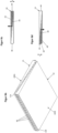
- FIG 7 comprehensively the Figures 7a and 7b A further embodiment of an optical arrangement 10 according to the invention is shown in schematic diagrams. Elements of this embodiment that are similar to elements of the embodiments of the invention already described are identified with identical reference numerals.
- the optical arrangement 10 according to Figure 7 has two optical elements 1A, 1B.
- the optical elements 1A, 1B of the embodiment of the optical arrangement 10 according to Figure 7 are identical to the optical elements 1A, 1B as well as to the embodiment according to Figure 6 explained. Even with the optical arrangement according to Figure 7 These optical elements 1A, 1B are inserted vertically into one another.
- the optical elements 1A, 1B are arranged in such a way that the light coupling sections 100A, 100B of the two optical elements 1A, 1B each form the same horizontal extension end of the optical arrangement 10. Accordingly, when using an optical arrangement 10 as intended according to Figure 7 the light sources 4A, 4B, which are arranged on the light coupling sections 100A, 100B of the two optical elements 1A, 1B, are arranged on the same horizontal extension end of the optical arrangement 10.
- An optical arrangement according to Figure 7 can be particularly advantageous for use in luminaires, since then the provision of light sources 4A, 4B has to be made on only one side of the optical arrangement 10 and accordingly a electrical contacting of the light sources 4A, 4B is simplified. As a result, the optical arrangement 10 according to Figure 7 This means that light is emitted homogeneously both vertically upwards and vertically downwards over a large radiation surface.
- FIG 8 comprehensively the Figures 8a and 8b A further embodiment of an optical arrangement 10 according to the invention is shown in schematic diagrams. Elements of this embodiment that are similar to elements of the already described embodiment of the invention are marked with identical reference numerals.
- the optical arrangement 10 according to Figure 8 has two optical elements 1A, 1B.
- the optical elements 1A, 1B each have a different geometric shape, which is why these two optical elements 1A, 1B each provide a different light distribution.
- the surface normals of the light output sections 200A, 200B of the two optical elements 1A, 1B point in the same direction.
- First light sources 4A are arranged on the light input section 100A of the first optical element 1A.
- Second light sources 4B are arranged on the light input section 100B of the second optical element 1B.
- Each of the light sources 4A, 4B is assigned to exactly one of the light guide sections 2A, 2B.
- the first light sources 4A, which are arranged on the first light input section 100A of the first optical element 1A, can be controlled independently of the second light sources 4B, which are arranged on the light input section 100B of the second optical element 1B. Since the two optical elements 1A, 1B each provide a different light distribution, the light distribution curve provided by the optical arrangement can be specifically selected by specifically controlling either the first light sources 4A or the second light sources 4B.
- FIG. 9 is a schematic diagram of a section of an embodiment of a lamp according to the invention. Elements of this embodiment that are similar to elements of the embodiments of the invention already described are identified by identical reference numerals.
- the embodiment described has an optical element 1.
- the optical element 1 has, which is generally advantageous according to the invention regardless of the embodiment described, two different groups of light-guiding sections, namely a first group of first light-guiding sections 21 and a second group of second light-guiding sections 22.
- the first and second light-guiding sections 21, 22 are arranged alternately.
- the first light-guiding sections 21 provide a different light distribution than the second light-guiding sections 22.
- Each of the light-guiding sections 21, 22 is assigned a light source 4.
- the light sources 4 are divided into two groups that can be controlled independently of one another.
- a first group of light sources 4 is assigned to the first light guide sections 21, a second group of light sources 4 is assigned to the second light guide sections 22. Since the two groups can be controlled independently of one another, the light distribution curve emitted by the luminaire can be specifically selected by selecting the control of the first or the second group of light sources 4, since when the first group of light sources 4 is controlled, the light distribution determined by the first light guide sections 21 with the resulting light distribution curve is used, and when the second group of light sources 4 is controlled, the light distribution provided by the second light guide sections 22 and thus the light distribution curve emitted is used.
- FIG 10 A further embodiment of a lamp according to the invention is shown in a section in a schematic diagram. Elements of this embodiment that are similar to elements of the already described embodiment of the invention are marked with identical reference numerals.
- the lamp comprises an optical element 1.
- this optical element 1 has a first group of first light guide sections 21 and a second group of second light guide sections 22, wherein the first light guide sections 21 provide a different light distribution than the second light guide sections 22.
- Each of the light guide sections 21, 22 is assigned an LED unit 41, 42.
- Each LED unit 41, 42 has two LEDs with different light colors, which can be controlled independently of one another.
- a first group of LED units 41 can be controlled independently of a second group of LED units 42, and in addition, the light sources of different light colors that are assigned to one of the groups of LED units 41, 42 can be controlled independently of one another. Accordingly, in the embodiment according to the invention according to Figure 10 Both the light colour emitted by the luminaire and the light distribution curve emitted by the luminaire can be adjusted.
Landscapes
- Physics & Mathematics (AREA)
- General Physics & Mathematics (AREA)
- Optics & Photonics (AREA)
- Non-Portable Lighting Devices Or Systems Thereof (AREA)
Claims (14)
- Élément optique (1, 1A, 1B) pour le guidage de la lumière dans un luminaire, l'élément optique comprenant un corps de lentille dont la surface forme une section de couplage de lumière (100, 100A, 100B) pour coupler un faisceau lumineux (40) dans le corps de lentille et une section de découplage de lumière (200, 200A, 200B) pour découpler le faisceau lumineux (40) du corps de lentille, dans lequelle corps de lentille comporte plusieurs sections de guidage de lumière (2, 2A, 2B) qui sont reliées les unes aux autres de manière à guider la lumière et qui sont réparties sur un plan de coupe horizontal, chaque section de guidage de lumière (2, 2A, 2B) ayant un tracé continu entre ses deux extrémités longitudinales dans le plan de coupe horizontal et étant limitée latéralement par rapport à son tracé par deux extrémités d'extension latérales opposées, chaque section de guidage de lumière (2, 2A, 2B) étant espacée latéralement de ses sections de guidage de lumière (2, 2A, 2B) qui sont latéralement adjacentes dans le plan de coupe horizontal, de sorte que les sections de guidage de lumière (2, 2A, 2B) représentent des sections mutuellement espacées du corps de lentille et qu'un espace libre est disposé dans chaque cas entre deux sections de guidage de lumière latéralement adjacentes (2, 2A, 2B) et que chaque section de guidage de lumière (2, 2A, 2B) est configurée pour guider le faisceau lumineux le long de son tracé continu entre ses extrémités d'extension latérales, au moins une pluralité de sections de guidage de lumière (2, 2A, 2B) ayant une longueur d'extension verticale qui diminue avec l'augmentation de la distance horizontale par rapport à la section de couplage de lumière (100) et chaque section de guidage de lumière (2, 2A, 2B) s'étendant sur une section verticale du corps de lentille qui représente au moins 30 % de la longueur d'extension verticale totale du corps de lentille dans la plage horizontale sur laquelle la section de guidage de lumière respective (2, 2A, 2B) s'étend, chaque section de guidage de lumière (2, 2A, 2B) étant latéralement espacée de ses sections de guidage de lumière latéralement adjacentes (2, 2A, 2B) à travers cette section verticale du corps de lentille, en particulier la pluralité des sections de guidage de lumière (2, 2A, 2B) étant reliées les unes aux autres de manière à guider la lumière à travers une première section (11, 11A) du corps de la lentille qui forme au moins une partie de la section de couplage de lumière (100, 100A, 100B) et qui, à partir d'une extrémité verticale de chacune de ces sections de guidage de lumière (2, 2A, 2B), s'étend comme une extension verticale de la section de guidage de lumière respective (2, 2A, 2B) de manière ininterrompue jusqu'à la section de couplage de la lumière,dans lequella pluralité de sections de guidage de lumière (2, 2A, 2B) sont reliées les unes aux autres de manière à guider la lumière au moyen d'une deuxième section (12, 12A) du corps de la lentille qui forme au moins une partie de la section de découplage de la lumière (200, 200A, 200B), la deuxième section (12, 12A) étant disposée sur une deuxième extrémité verticale de chacune de ces sections de guidage de lumière (2, 2A, 2B) et formée comme une extension verticale de chacune des sections de guidage de lumière (2, 2A, 2B) et s'étendant de manière ininterrompue à partir de cette deuxième extrémité verticale jusqu'à la section de découplage de lumière (200, 200A, 200B),et dans lequeli) la section de couplage de lumière (100, 100A, 100B) est formée par une extrémité d'extension horizontale du corps de lentille, les sections de guidage de lumière (2, 2A, 2B) s'étendant avec leur tracé respectif horizontalement loin de la section de couplage de lumière (100, 100A, 100B),
ouii) la section de couplage de lumière (100, 100A, 100B) est disposée horizontalement dans l'extension du corps de lentille et les sections de guidage de lumière (2, 2A, 2B) sont disposées horizontalement autour de la section de couplage de lumière (100, 100A, 100B) et s'étendent avec leur tracé respectif horizontalement loin de la section de couplage de lumière (100, 100A, 100B). - Élément optique (1, 1A, 1B) selon la revendication 1,
caractérisé en ce que
au moins plusieurs des sections de guidage de lumière (2, 2A, 2B) sont reliées entre elles de manière à guider la lumière à travers une première section de corps (11) de la lentille, première section de corps qui forme au moins une partie de la section de couplage de lumière (100, 100A, 100B) et/ou sont reliées entre elles de manière à guider la lumière à travers une deuxième section de corps (12, 12A, 12B) de la lentille, deuxième section de corps qui forme au moins une partie de la section de découplage de lumière (200, 200A, 200B). - Élément optique (1, 1A, 1B) selon l'une quelconque des revendications précédentes,
caractérisé en ce que
au moins plusieurs des sections de guidage de lumière (2, 2A, 2B) sont reliées entre elles à une première de leurs extrémités longitudinales de manière à guider la lumière. - Elément optique (1, 1A, 1B) selon l'une quelconque des revendications précédentes,
caractérisé en ce queau moins plusieurs de sections de guidage de lumière (2, 2A, 2B) s'étendent sur au moins 50%, en particulier au moins plus de 70%, d'une longueur d'extension verticale du corps de lentille et sont espacées latéralement les unes des autres sur toute leur longueur d'extension
et/ou en ce queau moins plus de 50 % de la longueur d'extension verticale du corps de lentille dans chaque plan de coupe horizontal au moins 50 % de l'extension plane du corps de lentille sont formés par une pluralité de sections de guidage de la lumière (2, 2A, 2B). - Elément optique (1, 1A, 1B) selon l'une quelconque des revendications précédentes,
caractérisé en ce que
la section de couplage de lumière (100, 100A, 100B) est disposée dans une direction horizontale entre des sections de guidage de lumière (2A, 2B) opposées l'une à l'autre dans cette direction horizontale et relie ces sections de guidage de lumière (2, 2A, 2B) l'une à l'autre et/ou que les sections de guidage de lumière (2, 2A, 2B) forment une disposition en étoile autour de la section de couplage de lumière (100, 100A, 100B) et sont reliées l'une à l'autre par l'intermédiaire de la section de couplage de lumière (100, 100A, 100B). - Élément optique (1, 1A, 1B) selon l'une quelconque des revendications précédentes,
caractérisé en ce que
les sections de guidage de lumière (2, 2A, 2B) forment au moins une extrémité verticale du corps de la lentille. - Elément optique (1, 1A, 1B) selon l'une quelconque des revendications précédentes,
caractérisé en ce que
un espace intermédiaire est prévu latéralement entre deux sections de guidage de lumière (2, 2A, 2B) adjacentes qui présente une section transversale en forme de V dans le plan de coupe horizontal, la pointe du V étant notamment orientée vers la section de couplage de lumière (100, 100A, 100B). - Élément optique (1, 1A, 1B) selon l'une quelconque des revendications précédentes,
caractérisé en ce que
la section de découplage de lumière (200, 200A, 200B) s'étend le long d'un plan horizontal. - Système optique (10) comprenant au moins deux éléments optiques (1, 1A, 1B) selon l'une quelconque des revendications précédentes,
caractérisé en ce que
au moins une partie, en particulier une pluralité, des sections de guidage de lumière (2A) d'un premier élément optique (1A) sont disposées horizontalement entre des sections de guidage de lumière (2B) d'un deuxième élément optique (1B) et se chevauchent verticalement avec ces sections de guidage de lumière (2B) du deuxième élément optique (1B), dans lequel, en particulier, une normale de surface de la section de découplage de lumière (200A) du premier élément optique (1A) et une normale de surface de la section de découplage de lumière (200B) du deuxième élément optique (1B) pointent dans la même direction ou dans des directions mutuellement opposées, dans lequel, en particulier, la normale de surface de la section de découplage de lumière (200A) du premier élément optique (1A) pointe verticalement vers le haut et la normale de surface de la section de découplage de lumière (200B) du deuxième élément optique (1B) pointe verticalement vers le bas. - Système optique (10) selon la revendication 9,
caractérisé en ce que
des DEL d'une première couleur de lumière sont disposées dans la section de couplage de lumière (100A) du premier élément optique (1A) et des DEL d'une deuxième couleur de lumière sont disposées dans la section de couplage de lumière (100B) du deuxième élément optique (1B), la première couleur de lumière étant différente de la deuxième couleur de lumière, dans lequel, en particulier, précisément une ou précisément un groupe de DEL de la première couleur de lumière est attribué respectivement à chacune des au moins quelques sections de guidage de lumière (2A) ou respectivement à un groupe de sections de guidage de lumière (2A) du premier élément optique (1A) et précisément une ou précisément un groupe de DEL de la deuxième couleur de lumière est attribué respectivement à chacune des au moins quelques sections de guidage de lumière (2B) ou respectivement à un groupe de sections de guidage de lumière (2B) du deuxième élément optique (1B). - Système optique selon l'une quelconque des revendications 9 ou 10,
caractérisé en ce que
le premier élément optique (1A) est associé à une première courbe de répartition de la lumière et le deuxième élément optique (1B) est associé à une deuxième courbe de répartition de la lumière, les deux courbes de répartition de la lumière étant différentes l'une de l'autre. - Luminaire comprenant un élément optique (1, 1A, 1B) selon l'une quelconque des revendications 1 à 9 et en particulier un système optique (10) selon l'une quelconque des revendications 9 à 11, dans lequel le luminaire comprend une source lumineuse, qui comprend en particulier une ou plusieurs LED, ainsi qu'une unité de commande pour commander la source lumineuse, dans lequel en particulier dans une majorité des sections de guidage de lumière (2, 2A, 2B) précisément une unité LED disposée sur la section de couplage de lumière (100, 100A, 100B) est affectée à chacune des sections de guidage de lumière (2, 2A, 2B) ou à chaque groupe de sections de guidage de lumière (2A, 2B), l'unité de commande étant configurée en particulier pour commander un premier groupe d'unités LED indépendamment d'un second groupe d'unités LED.
- Luminaire selon la revendication 12, comprenant un système optique (10) selon la revendication 11,
caractérisé en ce que
les normales de surface des sections de découplage de lumière (200A, 200B) des deux éléments optiques (1A, 1B) du système optique (10) pointent dans la même direction et qu'à la section de couplage de lumière (100A) du premier élément optique est disposé un premier des groupes d'unités LED et à la section de couplage de lumière (100B) du second élément optique (100B) est disposé un second des groupes d'unités LED, l'unité de commande étant configurée pour commander les deux groupes indépendamment l'un de l'autre afin d'assurer la sélection d'une distribution lumineuse rayonnée par le système optique (10) lors de l'utilisation du luminaire. - Luminaire selon l'une quelconque des revendications 12 ou 13,
caractérisé en ce queles unités LED du premier groupe d'unités LED sont chacune disposées sur des sections de guidage de lumière (2, 2A, 2B) qui fournissent une première répartition de la lumière et en ce que les unités LED du deuxième groupe d'unités LED sont chacune disposées sur des sections de guidage de lumière (2, 2A, 2B) qui fournissent une deuxième répartition de la lumière
et/ou en ce quele premier groupe d'unités LED comprend exclusivement des LED ayant une première couleur de lumière et le deuxième groupe d'unités LED comprend exclusivement des LED ayant une deuxième couleur de lumière différente de la première couleur de lumière ou que les unités LED comprennent respectivement des LED ayant une première couleur de lumière et des LED ayant une deuxième couleur de lumière, les LED ayant une première couleur de lumière, qui appartiennent à un groupe particulier d'unités LED, pouvant être commandées par l'unité de commande indépendamment des LED ayant une deuxième couleur de lumière qui appartiennent à ce groupe particulier.
Applications Claiming Priority (1)
| Application Number | Priority Date | Filing Date | Title |
|---|---|---|---|
| DE102017111912.4A DE102017111912A1 (de) | 2017-05-31 | 2017-05-31 | Modularer Lichtleiter |
Publications (2)
| Publication Number | Publication Date |
|---|---|
| EP3410006A1 EP3410006A1 (fr) | 2018-12-05 |
| EP3410006B1 true EP3410006B1 (fr) | 2024-12-18 |
Family
ID=62492510
Family Applications (1)
| Application Number | Title | Priority Date | Filing Date |
|---|---|---|---|
| EP18175191.8A Active EP3410006B1 (fr) | 2017-05-31 | 2018-05-30 | Guide d'ondes optiques modulaire |
Country Status (2)
| Country | Link |
|---|---|
| EP (1) | EP3410006B1 (fr) |
| DE (1) | DE102017111912A1 (fr) |
Citations (3)
| Publication number | Priority date | Publication date | Assignee | Title |
|---|---|---|---|---|
| US7160010B1 (en) * | 2005-11-15 | 2007-01-09 | Visteon Global Technologies, Inc. | Light manifold for automotive light module |
| US20140362588A1 (en) * | 2013-06-06 | 2014-12-11 | T.Y.C. Brother Industrial Co., Ltd. | Light guide lens |
| DE102015222495A1 (de) * | 2015-11-13 | 2017-05-18 | Automotive Lighting Reutlingen Gmbh | Vorsatzoptik und Vorsatzoptikanordnung mit mehreren Vorsatzoptiken |
Family Cites Families (5)
| Publication number | Priority date | Publication date | Assignee | Title |
|---|---|---|---|---|
| JPH11284803A (ja) * | 1998-03-27 | 1999-10-15 | Citizen Electronics Co Ltd | 線状光源ユニット |
| US8491174B2 (en) * | 2010-01-07 | 2013-07-23 | Rambus Delaware Llc | Light emitting assembly |
| JP5440857B2 (ja) * | 2010-03-05 | 2014-03-12 | スタンレー電気株式会社 | 車両用灯具ユニット、及び、車両用灯具 |
| JP5396498B2 (ja) * | 2012-03-02 | 2014-01-22 | 株式会社エス・ケー・ジー | 発光装置 |
| DE202013005301U1 (de) * | 2013-06-11 | 2013-07-25 | T.Y.C. Brother Industrial Co., Ltd. | Einheitliche Leuchtenlinse für Fahrzeuge |
-
2017
- 2017-05-31 DE DE102017111912.4A patent/DE102017111912A1/de active Pending
-
2018
- 2018-05-30 EP EP18175191.8A patent/EP3410006B1/fr active Active
Patent Citations (3)
| Publication number | Priority date | Publication date | Assignee | Title |
|---|---|---|---|---|
| US7160010B1 (en) * | 2005-11-15 | 2007-01-09 | Visteon Global Technologies, Inc. | Light manifold for automotive light module |
| US20140362588A1 (en) * | 2013-06-06 | 2014-12-11 | T.Y.C. Brother Industrial Co., Ltd. | Light guide lens |
| DE102015222495A1 (de) * | 2015-11-13 | 2017-05-18 | Automotive Lighting Reutlingen Gmbh | Vorsatzoptik und Vorsatzoptikanordnung mit mehreren Vorsatzoptiken |
Also Published As
| Publication number | Publication date |
|---|---|
| DE102017111912A1 (de) | 2018-12-06 |
| EP3410006A1 (fr) | 2018-12-05 |
Similar Documents
| Publication | Publication Date | Title |
|---|---|---|
| EP2622260B1 (fr) | Dispositif d'émission de lumière dirigée | |
| EP1022187B2 (fr) | Feu de véhicule | |
| EP3084496B1 (fr) | Élément optique et système d'émission de lumière | |
| EP2893249B1 (fr) | Unité d'éclairage destinée à un projecteur | |
| EP1640656B1 (fr) | Guides de lumière pour lampes, notamment pour lampes de véhicule | |
| EP2729838B1 (fr) | Élément optique | |
| DE102016100207B4 (de) | Signalleuchte | |
| DE102008021290B4 (de) | Lichtleiterstruktur für eine Kraftfahrzeugbeleuchtungseinrichtung und Kraftfahrzeugbeleuchtungseinrichtung mit einer solchen Lichtleiterstruktur | |
| WO2016070210A1 (fr) | Système d'éclairage pour véhicule à moteur | |
| DE102009005351A1 (de) | Lichtleiter für eine Lampe | |
| DE10055561A1 (de) | Beleuchtungseinrichtung | |
| DE19939087A1 (de) | Lichtleiter | |
| DE102014206593A1 (de) | Kraftfahrzeugleuchte mit Wischeffekt | |
| DE102007049861B4 (de) | Lichtleiterstruktur für einen Kraftfahrzeugscheinwerfer oder eine Kraftfahrzeugleuchte | |
| EP1106905A2 (fr) | Luminaire | |
| EP3410006B1 (fr) | Guide d'ondes optiques modulaire | |
| DE10341219A1 (de) | Leuchte zur Anbringung an einer Gebäudefläche oder Gebäudeteilfläche | |
| EP2746650B1 (fr) | Lampe dotée d'un élément de guidage de la lumière courbé | |
| AT520398B1 (de) | Beleuchtungs- und/oder signalisierungsvorrichtung für ein kraftfahrzeug | |
| DE202015104882U1 (de) | Beleuchtungsanordnung | |
| WO2016146622A1 (fr) | Élément optique destiné à influer sur la quantité de lumière émise par des sources lumineuses | |
| EP3212997B1 (fr) | Élément optique ainsi qu'ensemble d'émission de lumière comprenant un élément optique | |
| EP2989378B1 (fr) | Lampe à led à distributions lumineuses réglables | |
| DE202017107771U1 (de) | Lichtmischleiter und Leuchte mit Lichtmischleiter | |
| DE10231531B4 (de) | Schutzrohrleuchte |
Legal Events
| Date | Code | Title | Description |
|---|---|---|---|
| PUAI | Public reference made under article 153(3) epc to a published international application that has entered the european phase |
Free format text: ORIGINAL CODE: 0009012 |
|
| STAA | Information on the status of an ep patent application or granted ep patent |
Free format text: STATUS: THE APPLICATION HAS BEEN PUBLISHED |
|
| AK | Designated contracting states |
Kind code of ref document: A1 Designated state(s): AL AT BE BG CH CY CZ DE DK EE ES FI FR GB GR HR HU IE IS IT LI LT LU LV MC MK MT NL NO PL PT RO RS SE SI SK SM TR |
|
| AX | Request for extension of the european patent |
Extension state: BA ME |
|
| STAA | Information on the status of an ep patent application or granted ep patent |
Free format text: STATUS: REQUEST FOR EXAMINATION WAS MADE |
|
| 17P | Request for examination filed |
Effective date: 20190605 |
|
| RBV | Designated contracting states (corrected) |
Designated state(s): AL AT BE BG CH CY CZ DE DK EE ES FI FR GB GR HR HU IE IS IT LI LT LU LV MC MK MT NL NO PL PT RO RS SE SI SK SM TR |
|
| RAP1 | Party data changed (applicant data changed or rights of an application transferred) |
Owner name: TRILUX GMBH & CO. KG |
|
| STAA | Information on the status of an ep patent application or granted ep patent |
Free format text: STATUS: EXAMINATION IS IN PROGRESS |
|
| 17Q | First examination report despatched |
Effective date: 20200706 |
|
| P01 | Opt-out of the competence of the unified patent court (upc) registered |
Effective date: 20230527 |
|
| GRAP | Despatch of communication of intention to grant a patent |
Free format text: ORIGINAL CODE: EPIDOSNIGR1 |
|
| STAA | Information on the status of an ep patent application or granted ep patent |
Free format text: STATUS: GRANT OF PATENT IS INTENDED |
|
| INTG | Intention to grant announced |
Effective date: 20240710 |
|
| GRAS | Grant fee paid |
Free format text: ORIGINAL CODE: EPIDOSNIGR3 |
|
| GRAA | (expected) grant |
Free format text: ORIGINAL CODE: 0009210 |
|
| STAA | Information on the status of an ep patent application or granted ep patent |
Free format text: STATUS: THE PATENT HAS BEEN GRANTED |
|
| AK | Designated contracting states |
Kind code of ref document: B1 Designated state(s): AL AT BE BG CH CY CZ DE DK EE ES FI FR GB GR HR HU IE IS IT LI LT LU LV MC MK MT NL NO PL PT RO RS SE SI SK SM TR |
|
| REG | Reference to a national code |
Ref country code: GB Ref legal event code: FG4D Free format text: NOT ENGLISH |
|
| REG | Reference to a national code |
Ref country code: CH Ref legal event code: EP |
|
| REG | Reference to a national code |
Ref country code: DE Ref legal event code: R096 Ref document number: 502018015418 Country of ref document: DE |
|
| REG | Reference to a national code |
Ref country code: IE Ref legal event code: FG4D Free format text: LANGUAGE OF EP DOCUMENT: GERMAN |
|
| REG | Reference to a national code |
Ref country code: LT Ref legal event code: MG9D |
|
| PG25 | Lapsed in a contracting state [announced via postgrant information from national office to epo] |
Ref country code: HR Free format text: LAPSE BECAUSE OF FAILURE TO SUBMIT A TRANSLATION OF THE DESCRIPTION OR TO PAY THE FEE WITHIN THE PRESCRIBED TIME-LIMIT Effective date: 20241218 |
|
| PG25 | Lapsed in a contracting state [announced via postgrant information from national office to epo] |
Ref country code: FI Free format text: LAPSE BECAUSE OF FAILURE TO SUBMIT A TRANSLATION OF THE DESCRIPTION OR TO PAY THE FEE WITHIN THE PRESCRIBED TIME-LIMIT Effective date: 20241218 |
|
| PG25 | Lapsed in a contracting state [announced via postgrant information from national office to epo] |
Ref country code: BG Free format text: LAPSE BECAUSE OF FAILURE TO SUBMIT A TRANSLATION OF THE DESCRIPTION OR TO PAY THE FEE WITHIN THE PRESCRIBED TIME-LIMIT Effective date: 20241218 |
|
| PG25 | Lapsed in a contracting state [announced via postgrant information from national office to epo] |
Ref country code: NO Free format text: LAPSE BECAUSE OF FAILURE TO SUBMIT A TRANSLATION OF THE DESCRIPTION OR TO PAY THE FEE WITHIN THE PRESCRIBED TIME-LIMIT Effective date: 20250318 |
|
| REG | Reference to a national code |
Ref country code: NL Ref legal event code: MP Effective date: 20241218 |
|
| PG25 | Lapsed in a contracting state [announced via postgrant information from national office to epo] |
Ref country code: LV Free format text: LAPSE BECAUSE OF FAILURE TO SUBMIT A TRANSLATION OF THE DESCRIPTION OR TO PAY THE FEE WITHIN THE PRESCRIBED TIME-LIMIT Effective date: 20241218 Ref country code: GR Free format text: LAPSE BECAUSE OF FAILURE TO SUBMIT A TRANSLATION OF THE DESCRIPTION OR TO PAY THE FEE WITHIN THE PRESCRIBED TIME-LIMIT Effective date: 20250319 |
|
| PG25 | Lapsed in a contracting state [announced via postgrant information from national office to epo] |
Ref country code: RS Free format text: LAPSE BECAUSE OF FAILURE TO SUBMIT A TRANSLATION OF THE DESCRIPTION OR TO PAY THE FEE WITHIN THE PRESCRIBED TIME-LIMIT Effective date: 20250318 |
|
| PG25 | Lapsed in a contracting state [announced via postgrant information from national office to epo] |
Ref country code: NL Free format text: LAPSE BECAUSE OF FAILURE TO SUBMIT A TRANSLATION OF THE DESCRIPTION OR TO PAY THE FEE WITHIN THE PRESCRIBED TIME-LIMIT Effective date: 20241218 |
|
| PG25 | Lapsed in a contracting state [announced via postgrant information from national office to epo] |
Ref country code: SM Free format text: LAPSE BECAUSE OF FAILURE TO SUBMIT A TRANSLATION OF THE DESCRIPTION OR TO PAY THE FEE WITHIN THE PRESCRIBED TIME-LIMIT Effective date: 20241218 |
|
| PG25 | Lapsed in a contracting state [announced via postgrant information from national office to epo] |
Ref country code: PL Free format text: LAPSE BECAUSE OF FAILURE TO SUBMIT A TRANSLATION OF THE DESCRIPTION OR TO PAY THE FEE WITHIN THE PRESCRIBED TIME-LIMIT Effective date: 20241218 |
|
| PG25 | Lapsed in a contracting state [announced via postgrant information from national office to epo] |
Ref country code: ES Free format text: LAPSE BECAUSE OF FAILURE TO SUBMIT A TRANSLATION OF THE DESCRIPTION OR TO PAY THE FEE WITHIN THE PRESCRIBED TIME-LIMIT Effective date: 20241218 |
|
| PGFP | Annual fee paid to national office [announced via postgrant information from national office to epo] |
Ref country code: GB Payment date: 20250522 Year of fee payment: 8 |
|
| PG25 | Lapsed in a contracting state [announced via postgrant information from national office to epo] |
Ref country code: IS Free format text: LAPSE BECAUSE OF FAILURE TO SUBMIT A TRANSLATION OF THE DESCRIPTION OR TO PAY THE FEE WITHIN THE PRESCRIBED TIME-LIMIT Effective date: 20250418 |
|
| PG25 | Lapsed in a contracting state [announced via postgrant information from national office to epo] |
Ref country code: PT Free format text: LAPSE BECAUSE OF FAILURE TO SUBMIT A TRANSLATION OF THE DESCRIPTION OR TO PAY THE FEE WITHIN THE PRESCRIBED TIME-LIMIT Effective date: 20250421 |
|
| PG25 | Lapsed in a contracting state [announced via postgrant information from national office to epo] |
Ref country code: EE Free format text: LAPSE BECAUSE OF FAILURE TO SUBMIT A TRANSLATION OF THE DESCRIPTION OR TO PAY THE FEE WITHIN THE PRESCRIBED TIME-LIMIT Effective date: 20241218 |
|
| PGFP | Annual fee paid to national office [announced via postgrant information from national office to epo] |
Ref country code: FR Payment date: 20250521 Year of fee payment: 8 |
|
| PG25 | Lapsed in a contracting state [announced via postgrant information from national office to epo] |
Ref country code: RO Free format text: LAPSE BECAUSE OF FAILURE TO SUBMIT A TRANSLATION OF THE DESCRIPTION OR TO PAY THE FEE WITHIN THE PRESCRIBED TIME-LIMIT Effective date: 20241218 |
|
| PG25 | Lapsed in a contracting state [announced via postgrant information from national office to epo] |
Ref country code: SK Free format text: LAPSE BECAUSE OF FAILURE TO SUBMIT A TRANSLATION OF THE DESCRIPTION OR TO PAY THE FEE WITHIN THE PRESCRIBED TIME-LIMIT Effective date: 20241218 |
|
| PG25 | Lapsed in a contracting state [announced via postgrant information from national office to epo] |
Ref country code: CZ Free format text: LAPSE BECAUSE OF FAILURE TO SUBMIT A TRANSLATION OF THE DESCRIPTION OR TO PAY THE FEE WITHIN THE PRESCRIBED TIME-LIMIT Effective date: 20241218 |
|
| PG25 | Lapsed in a contracting state [announced via postgrant information from national office to epo] |
Ref country code: IT Free format text: LAPSE BECAUSE OF FAILURE TO SUBMIT A TRANSLATION OF THE DESCRIPTION OR TO PAY THE FEE WITHIN THE PRESCRIBED TIME-LIMIT Effective date: 20241218 |
|
| PG25 | Lapsed in a contracting state [announced via postgrant information from national office to epo] |
Ref country code: SE Free format text: LAPSE BECAUSE OF FAILURE TO SUBMIT A TRANSLATION OF THE DESCRIPTION OR TO PAY THE FEE WITHIN THE PRESCRIBED TIME-LIMIT Effective date: 20241218 |
|
| REG | Reference to a national code |
Ref country code: DE Ref legal event code: R097 Ref document number: 502018015418 Country of ref document: DE |
|
| PG25 | Lapsed in a contracting state [announced via postgrant information from national office to epo] |
Ref country code: DK Free format text: LAPSE BECAUSE OF FAILURE TO SUBMIT A TRANSLATION OF THE DESCRIPTION OR TO PAY THE FEE WITHIN THE PRESCRIBED TIME-LIMIT Effective date: 20241218 |
|
| PGFP | Annual fee paid to national office [announced via postgrant information from national office to epo] |
Ref country code: DE Payment date: 20250728 Year of fee payment: 8 |
|
| PLBE | No opposition filed within time limit |
Free format text: ORIGINAL CODE: 0009261 |
|
| STAA | Information on the status of an ep patent application or granted ep patent |
Free format text: STATUS: NO OPPOSITION FILED WITHIN TIME LIMIT |
|
| REG | Reference to a national code |
Ref country code: CH Ref legal event code: L10 Free format text: ST27 STATUS EVENT CODE: U-0-0-L10-L00 (AS PROVIDED BY THE NATIONAL OFFICE) Effective date: 20251029 |
|
| 26N | No opposition filed |
Effective date: 20250919 |
|
| REG | Reference to a national code |
Ref country code: CH Ref legal event code: H13 Free format text: ST27 STATUS EVENT CODE: U-0-0-H10-H13 (AS PROVIDED BY THE NATIONAL OFFICE) Effective date: 20251223 |
|
| PG25 | Lapsed in a contracting state [announced via postgrant information from national office to epo] |
Ref country code: LU Free format text: LAPSE BECAUSE OF NON-PAYMENT OF DUE FEES Effective date: 20250530 |
|
| PG25 | Lapsed in a contracting state [announced via postgrant information from national office to epo] |
Ref country code: CH Free format text: LAPSE BECAUSE OF NON-PAYMENT OF DUE FEES Effective date: 20250531 |
|
| REG | Reference to a national code |
Ref country code: BE Ref legal event code: MM Effective date: 20250531 |
|
| PG25 | Lapsed in a contracting state [announced via postgrant information from national office to epo] |
Ref country code: MC Free format text: LAPSE BECAUSE OF FAILURE TO SUBMIT A TRANSLATION OF THE DESCRIPTION OR TO PAY THE FEE WITHIN THE PRESCRIBED TIME-LIMIT Effective date: 20241218 |
|
| PG25 | Lapsed in a contracting state [announced via postgrant information from national office to epo] |
Ref country code: IE Free format text: LAPSE BECAUSE OF NON-PAYMENT OF DUE FEES Effective date: 20250530 |
|
| PG25 | Lapsed in a contracting state [announced via postgrant information from national office to epo] |
Ref country code: BE Free format text: LAPSE BECAUSE OF NON-PAYMENT OF DUE FEES Effective date: 20250531 |