EP3410013B1 - Système de distribution de gaz de combustion - Google Patents
Système de distribution de gaz de combustion Download PDFInfo
- Publication number
- EP3410013B1 EP3410013B1 EP17743989.0A EP17743989A EP3410013B1 EP 3410013 B1 EP3410013 B1 EP 3410013B1 EP 17743989 A EP17743989 A EP 17743989A EP 3410013 B1 EP3410013 B1 EP 3410013B1
- Authority
- EP
- European Patent Office
- Prior art keywords
- gas
- combustion gas
- fuel
- heat
- compressor
- Prior art date
- Legal status (The legal status is an assumption and is not a legal conclusion. Google has not performed a legal analysis and makes no representation as to the accuracy of the status listed.)
- Active
Links
Images
Classifications
-
- F—MECHANICAL ENGINEERING; LIGHTING; HEATING; WEAPONS; BLASTING
- F23—COMBUSTION APPARATUS; COMBUSTION PROCESSES
- F23C—METHODS OR APPARATUS FOR COMBUSTION USING FLUID FUEL OR SOLID FUEL SUSPENDED IN A CARRIER GAS OR AIR
- F23C9/00—Combustion apparatus characterised by arrangements for returning combustion products or flue gases to the combustion chamber
- F23C9/06—Combustion apparatus characterised by arrangements for returning combustion products or flue gases to the combustion chamber for completing combustion
-
- F—MECHANICAL ENGINEERING; LIGHTING; HEATING; WEAPONS; BLASTING
- F23—COMBUSTION APPARATUS; COMBUSTION PROCESSES
- F23C—METHODS OR APPARATUS FOR COMBUSTION USING FLUID FUEL OR SOLID FUEL SUSPENDED IN A CARRIER GAS OR AIR
- F23C7/00—Combustion apparatus characterised by arrangements for air supply
- F23C7/008—Flow control devices
-
- F—MECHANICAL ENGINEERING; LIGHTING; HEATING; WEAPONS; BLASTING
- F23—COMBUSTION APPARATUS; COMBUSTION PROCESSES
- F23J—REMOVAL OR TREATMENT OF COMBUSTION PRODUCTS OR COMBUSTION RESIDUES; FLUES
- F23J15/00—Arrangements of devices for treating smoke or fumes
-
- F—MECHANICAL ENGINEERING; LIGHTING; HEATING; WEAPONS; BLASTING
- F23—COMBUSTION APPARATUS; COMBUSTION PROCESSES
- F23K—FEEDING FUEL TO COMBUSTION APPARATUS
- F23K5/00—Feeding or distributing other fuel to combustion apparatus
- F23K5/002—Gaseous fuel
-
- F—MECHANICAL ENGINEERING; LIGHTING; HEATING; WEAPONS; BLASTING
- F23—COMBUSTION APPARATUS; COMBUSTION PROCESSES
- F23L—SUPPLYING AIR OR NON-COMBUSTIBLE LIQUIDS OR GASES TO COMBUSTION APPARATUS IN GENERAL ; VALVES OR DAMPERS SPECIALLY ADAPTED FOR CONTROLLING AIR SUPPLY OR DRAUGHT IN COMBUSTION APPARATUS; INDUCING DRAUGHT IN COMBUSTION APPARATUS; TOPS FOR CHIMNEYS OR VENTILATING SHAFTS; TERMINALS FOR FLUES
- F23L7/00—Supplying non-combustible liquids or gases, other than air, to the fire, e.g. oxygen, steam
-
- F—MECHANICAL ENGINEERING; LIGHTING; HEATING; WEAPONS; BLASTING
- F23—COMBUSTION APPARATUS; COMBUSTION PROCESSES
- F23C—METHODS OR APPARATUS FOR COMBUSTION USING FLUID FUEL OR SOLID FUEL SUSPENDED IN A CARRIER GAS OR AIR
- F23C2202/00—Fluegas recirculation
- F23C2202/30—Premixing fluegas with combustion air
-
- F—MECHANICAL ENGINEERING; LIGHTING; HEATING; WEAPONS; BLASTING
- F23—COMBUSTION APPARATUS; COMBUSTION PROCESSES
- F23C—METHODS OR APPARATUS FOR COMBUSTION USING FLUID FUEL OR SOLID FUEL SUSPENDED IN A CARRIER GAS OR AIR
- F23C2202/00—Fluegas recirculation
- F23C2202/50—Control of recirculation rate
-
- F—MECHANICAL ENGINEERING; LIGHTING; HEATING; WEAPONS; BLASTING
- F23—COMBUSTION APPARATUS; COMBUSTION PROCESSES
- F23J—REMOVAL OR TREATMENT OF COMBUSTION PRODUCTS OR COMBUSTION RESIDUES; FLUES
- F23J15/00—Arrangements of devices for treating smoke or fumes
- F23J15/06—Arrangements of devices for treating smoke or fumes of coolers
-
- F—MECHANICAL ENGINEERING; LIGHTING; HEATING; WEAPONS; BLASTING
- F23—COMBUSTION APPARATUS; COMBUSTION PROCESSES
- F23L—SUPPLYING AIR OR NON-COMBUSTIBLE LIQUIDS OR GASES TO COMBUSTION APPARATUS IN GENERAL ; VALVES OR DAMPERS SPECIALLY ADAPTED FOR CONTROLLING AIR SUPPLY OR DRAUGHT IN COMBUSTION APPARATUS; INDUCING DRAUGHT IN COMBUSTION APPARATUS; TOPS FOR CHIMNEYS OR VENTILATING SHAFTS; TERMINALS FOR FLUES
- F23L15/00—Heating of air supplied for combustion
- F23L15/04—Arrangements of recuperators
-
- Y—GENERAL TAGGING OF NEW TECHNOLOGICAL DEVELOPMENTS; GENERAL TAGGING OF CROSS-SECTIONAL TECHNOLOGIES SPANNING OVER SEVERAL SECTIONS OF THE IPC; TECHNICAL SUBJECTS COVERED BY FORMER USPC CROSS-REFERENCE ART COLLECTIONS [XRACs] AND DIGESTS
- Y02—TECHNOLOGIES OR APPLICATIONS FOR MITIGATION OR ADAPTATION AGAINST CLIMATE CHANGE
- Y02E—REDUCTION OF GREENHOUSE GAS [GHG] EMISSIONS, RELATED TO ENERGY GENERATION, TRANSMISSION OR DISTRIBUTION
- Y02E20/00—Combustion technologies with mitigation potential
- Y02E20/34—Indirect CO2mitigation, i.e. by acting on non CO2directly related matters of the process, e.g. pre-heating or heat recovery
Definitions
- the present invention relates to a combustion gas supply system that supplies, as a heat source, a combustion gas generated by combusting a fuel.
- Combustion gases generated by combusting fuels have been utilized by various kinds of instruments and equipment as energy sources that supply thermal energy or power energy.
- a combustion gas is utilized as a power source, and the flow pressure of the combustion gas is converted into drive power or electric power.
- a combustion gas is used as a heat source, and the thermal energy of the combustion gas is transferred via heat exchange to a target substance to thereby heat the target substance, cause a change in its state (such as vaporization), cause a chemical reaction to progress, and so on.
- a combustor which generates a combustion gas adds a fuel to air to be used as an oxygen source and combusts them.
- the combustion efficiency is enhanced by compressing air, supplying it to the combustor, and combusting the fuel in the compressed air, and then a high-temperature pressurized combustion gas is generated.
- Patent Literature 1 Japanese Utility Model Registration No. 3179432
- Patent Literature 2 discloses the features specified in the preamble of claim 1, methods and systems for low emission power generation in hydrocarbon recovery processes.
- Patent Literature 4 discloses a high pressure atomized combustion equipment prevented from deterioration of condensation performance of its CO2 condenser due to soot and noncondensable gas.
- US2011314966 discloses an apparatus for producing a reducing gas for direct reduction iron-making including an internal-heating type reformer for reforming a natural gas by adding steam and oxygen to the natural gas and by partially burning the natural gas to generate reducing gas containing hydrogen and carbon monoxide; a remover for removing carbon dioxide from exhaust gas generated in the direct reduction iron-making; and a line for recycling as the reducing gas the exhaust gas from which the carbon dioxide is removed by the remover.
- EP2650503 discloses a power plant configured to include a recirculation loop about which a working fluid is recirculated.
- the present inventors have conducted an earnest research on addition of a compressor and power use, and discovered a simple configuration capable of suppressing increase in energy consumption by utilizing a used gas after being used as a heat source. As a result, the present inventors have reached the technique of the present invention.
- the present invention provides a combustion gas supply system as claimed in claim 1.
- reusing the used gas after the heat is consumed makes it possible to reduce the mechanical power of the compressor for the system as a whole, by effectively utilizing the residual pressure. It is therefore possible to provide a combustion gas supply system capable of adjusting the combustion conditions in a preferable manner and saving energy.
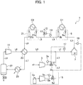
- FIG. 1 is a schematic diagram illustrating the configuration of a combustion gas supply system according to one embodiment of the present invention.
- a used gas that is a combustion gas after being used as a heat source is suitable to be re-pressurized by a low-compression ratio compressor and used if it is collected as is without releasing its pressure.
- a combustion gas as a heat source as in a boiler, a reactor, or the like
- decrease in pressure of the supplied combustion gas causes lowering its temperature, which is not preferable as a heat source.
- an apparatus that consumes the heat hereinafter, referred to as heat consumption apparatus is configured such that the pressure of a combustion gas therein is maintained while heat is supplied from the combustion gas.
- the pressure of a high-temperature pressurized combustion gas generated using compressed air in order to enhance the combustion efficiency is maintained inside the heat consumption apparatus, and the used gas discharged is a waste gas in a pressurized state such that the pressure of the unused combustion gas is substantially maintained excluding the pressure drop due to the resistance to flow and the like. Then, re-pressurizing and using this as a component of compressed air is very effective in reducing the power consumption of the compressor for the system as a whole. Also, although the oxygen content of the combustion gas decreases as a result of the consumption of oxygen in the combustion, the oxygen concentration is only about a half of that of air. Hence, by being mixed with normal air, the used gas can be utilized as compressed air to a satisfactory extent.
- a used gas after being used as a heat source is recovered with its pressure maintained, compressed by a re-pressurizing compressor so as to regain a pressure equivalent to the pressure of the compressed air, and supplied to a combustor as supplementary compressed air.
- the electric power consumed by the re-pressurizing compressor is such electric power that is required to compensate for the pressure of the combustion gas lost in the course of supplying the heat therein as a heat source.
- the present invention provides a combustion gas supply system capable of suppressing increase in cost due to increased supply of compressed air by efficiently recovering energy from the used gas being a combustion gas after being used as a heat source, and also of freely adjusting the combustion conditions via supply of compressed air so that a combustion gas suitable for the intended use can be supplied.
- Examples of the heat consumption apparatus C1 include apparatuses that heat a target substance or cause a change in its state (such as vaporization) by heating, such as a steam generator, a hot water generator, a thermic fluid heater, an air heater, and a hot gas generator, as well as reactors that heat a target substance to cause a chemical reaction therein to progress.
- the heat consumption apparatus C1 may also be a reactor using a catalyst containing an active metal such as Ni, Co, Fe, Pt, Ru, Rh, or Pd as its component.
- the kind of target substance to be heated and the purpose of the heating vary depending on the intended use of the heat consumption apparatus C1, and the temperature of the combustion gas and the flow rate at which it is supplied are appropriately adjusted in accordance with them.
- the combustion gas supply system 1 has an air compressor 3, a fuel supply device 5, a combustor 7, a gas supply and recovery section 9, and a re-pressurizing compressor 11.
- the air compressor 3 compresses air and supplies the compressed air to the combustor 7 through a flow channel L1.
- the fuel supply device 5 supplies a fuel into the compressed air through a flow channel L2.
- the combustor 7 receives the fuel and the compressed air supplied by the air compressor 3 and the fuel supply device 5 and combusts them to thereby generate a pressurized combustion gas.
- the fuel supply device 5 includes a fuel source 5a and a fuel compressor 5b.
- the pressurized combustion gas in the combustor 7 is supplied to the heat consumption apparatus C1 from a flow channel L3 through the gas supply and recovery section 9, and the pressurized combustion gas that the heat therein has been consumed is recovered as a used gas from the heat consumption apparatus C1.
- the gas supply and recovery section 9 includes a supply connection member 9a at an end of the flow channel L3 and a recovery connection member 9b at an end of a flow channel L4. They can connect the flow channels L3, L4 and the heat consumption apparatus C1 in a detachable manner and thereby allow the combustion gas supply system 1 and the heat consumption apparatus C1 to communicate with each other without a pressure loss.
- the pressurized combustion gas generated by the combustor 7 is supplied to the heat consumption apparatus C1 from the flow channel L3 through the gas supply and recovery section 9 while maintaining its pressure, and the pressurized combustion gas after the heat therein is consumed (used gas) is caused to flow back from the heat consumption apparatus C1 into the flow channel L4 while maintaining substantially its pressure excluding the pressure loss due to the flow resistance therein.
- the used gas (waste gas in a pressurized state) collected by the gas supply and recovery section 9 is discharged to the outside from the flow channel L4 through a flow channel L5 .
- a pressure meter 13 is provided on the flow channel L4, and a pressure adjustment valve 15 on the flow channel L5 is controlled based on its detection value, and the discharge of the used gas to the outside is controlled so as to maintain the pressure inside the combustion gas supply system 1 at a predetermined pressure.
- the pressure meter 13 of the flow channel L4 detects the pressure of the used gas, which is lower than the pressure of the pressurized combustion gas by the pressure loss. Hence, a pressure taking the pressure loss into account is set as the predetermined pressure.
- the pressure meter 13 may be provided to the flow channel L3 and the predetermined pressure in that case is set to the pressure of the pressurized combustion gas.
- the lost pressure of the used gas recovered from the flow channel L4 is compensated for by the re-pressurizing compressor 11, so that the used gas with its pressure raised to be equivalent to that of the compressed air is supplied to and mixed with the compressed air.
- the used gas with a compensated pressure is supplied to the combustor 7 together with the compressed air and the fuel as a mixture gas. Since the oxygen concentration of the compressed air to be supplied to the combustor 7 has a suitable range in view of combustion efficiency, the mixing ratio of the compressed air, the fuel and the used gas has an appropriate range.
- the fuel supply device 5 includes a flowmeter 5c and a flow rate adjustment valve 5d on the flow channel L2.
- the flowmeter 5c and the flow rate adjustment valve 5d are electrically connected to a temperature meter 19 which is installed on the flow channel L3 to detect the temperature of the combustion gas.
- the flow rate adjustment valve 5d is controlled based on the temperature detected by the temperature meter 19, and the flow rate of the compressed fuel is adjusted by the flow rate adjustment valve 5d.
- the temperature of the combustion gas is adjusted to the desired temperature.
- the gas supply and recovery section 21 is optional, and it may be omitted or provided in series downstream of the gas supply and recovery section 9 on the flow channel L4.
- the gas supply and recovery section 21 may be configured to be able to switch the connection between a state where the supply connection member 21a and the recovery connection member 21b are directly connected to each other and a state where they are connected to the heat consumption apparatus C2 so that it is possible to arbitrarily select connection to the heat consumption apparatus C2 or disconnection therefrom.
- the combustion gas supply system 1 includes a heat exchanger 23, a cooler 25, and a condensation separator 27, and moisture is removed from the used gas by gas-liquid separation utilizing cold condensation of water vapor.
- the part of the recovered used gas is supplied from the flow channel L6 to the cooler 25 on the flow channel L7 and cooled down to such a temperature that the part of the collected used gas can be supplied to the re-pressurizing compressor 11.
- the part of the collected used gas is then supplied to the condensation separator 27.
- the moisture condensed from the water vapor by the cooling of the used gas is separated from the used gas at the condensation separator 27 and removed to the outside.
- the used gas after removal of water vapor therefrom is introduced to the re-pressurizing compressor 11 from the condensation separator 27 through the flow channel L8 to be supplementarily compressed, so that the lost pressure due to the resistance to flow is compensated for and the used gas is therefore pressurized to the same pressure as the pressure of the compressed air.
- the heat exchanger 23 is provided upstream of the cooler 25.
- the used gas in the flow channel L6 to be reused exchanges heat with the used gas in the flow channel L8 supplementarily compressed by the re-pressurizing compressor 11, at the heat exchanger 23 before being cooled by the cooler 25.
- the compressed used gas in the flow channel L8 is lower in temperature than the used gas in the flow channel L6, and is heated at the heat exchanger 23 by receiving the residual heat of the used gas in the flow channel L6 and its temperature therefore gets close to the temperature of the used gas in the flow channel L6. Consequently, the used gas dried and pressurized to the same pressure as the pressure of the compressed air flows through the flow channel L9 at a temperature close to that at the time of the recovering from the heat consumption apparatus and joins to the compressed air and the fuel in the flow channel L1. In other words, the residual heat of the used gas in the flow channel L6 is effectively utilized as it is transferred to the supplementarily compressed used gas at the heat exchanger 23.
- An appropriate oxygen concentration of the compressed air to be supplied to the combustor 7 is preferably about 13 to 14vol% in view of energy saving. Since the oxygen concentration of air is about 20vol%, the used gas to be reused is preferably mixed so that its ratio (volume ratio) to the compressed air is about 1.5 to 1.8. Here, the proportion in volume of the compressed air in the mixture gas to be supplied to the combustor 7 is about 35 to 40% while the proportion in volume of the used gas is about 60 to 65%. Thus, in a state where the combustion gas supply system 1 of the present invention is in steady operation, about 60 to 65% of the used gas collected from the heat consumption apparatus C1 is reused, and the remaining part, which is about 35 to 40%, is discharged from the flow channel L5.
- combustion gas supply system 1 in FIG. 1 may be configured such that an expander is provided on the flow channel L5 to recover and reuse energy of the used gas discharged from the flow channel L5 as mechanical power. This further improves the energy efficiency.
- the combustor 7 is a pressurized combustor with pressure resistance capable of combusting a fuel in compressed air.
- the combustor 7 may be of any combustion type among an ignition type and a catalytic combustion type as long as it generates a combustion air by utilizing a combustion reaction.
- a catalytic combustion-type combustor is preferable in view of the stability of the combustion reaction and the like, and examples of the catalyst for the combustion include platinum- based catalysts and palladium-based catalysts.
- the required temperature of the combustion gas and the required amount of the combustion gas to be supplied vary depending on the intended use and usage conditions of the combustion gas at the heat consumption apparatus C1, and a combustor having a supply capability and thermal resistance suitable for the intended use and usage conditions may be selected as appropriate and used.
- the fuel used for the combustion is a flammable gas, i.e. a gas containing a flammable component such as carbon monoxide, hydrogen, or a hydrocarbon compound (such as methane) .
- the flammable component of the fuel may be either a single component or a mixture composition.
- Gaseous fuels typically used for gas turbines and the like are preferably usable, and examples include fuels such as natural gases, coal gasification fuels, and biogases.
- the heating value of the fuel per unit volume varies depending on the content of its flammable component, and the appropriate amount of compressed air to be supplied varies as well.
- the air compressor 3 may be any compressor that can be generally used for supplying combustion gas, and examples include a centrifugal compressor, an axial flow compressor, a reciprocating compressor, a diaphragm compressor, a twin-screw compressor, a single-screw compressor, a scroll compressor, and the like.
- a compressor capable of compressing air in a compression ratio (pressure ratio) of about 2.9 to 20.7 is preferably usable as the air compressor 3.
- the fuel compressor 5b may be any compressor that is capable of compressing the fuel gas to a pressure equivalent to the pressure of the compressed air, and one with a capacity corresponding to the flow rate at which the fuel is supplied is used.
- the fuel compressor 5b can be omitted in the case where the fuel is contained in a tank or the like including a pressure adjustment valve or the like.
- the re-pressurizing compressor 11 performs the supplementary pressurization in order to compensate for the lost pressure and therefore its pressure ratio required is lower than that of the air compressor 3 .
- the pressure loss caused by the flow resistance varies depending on the flow conditions in the heat consumption apparatuses C1, C2, but the pressure loss per apparatus can usually be predicted to be within the range of about 1.5 to 15% of the pressure at which the combustion gas is supplied (gauge pressure) .
- a compressor capable of compressing air in a pressure ratio of about 1.8 to 19.6 is preferably usable as the re-pressurizing compressor 11.
- a heat exchanger can be selected as appropriate from among typically used gas-gas heat exchangers and used as the heat exchanger 23. Examples include a stationary heat exchanger, a rotary regenerative heat exchanger, and a periodic-flow regenerative heat exchanger, and the heat exchanger 23 may be any of these types.
- the cooler 25 is actually a heat exchanger, and neither its cooling method nor type of coolant is limited.
- the cooler 25 may be any one capable of lowering the temperature of the used gas to such a temperature that the used gas can be supplied to the re-pressurizing compressor 11, and having durability against the pressure of the used gas.
- a gas-liquid heat exchanger is preferable in view of the cooling efficiency and the like, and a typically used water-cooling cooler is preferably usable.
- the condensation separator 27 can also be selected as appropriate from among typically used gas-liquid separators, and one having durability against the pressure of the used gas is used.
- the combustion gas supply system 1 has been described above as a system capable of selecting and replacing the heat consumption apparatus as necessary. In a case where changing the heat consumption apparatus is not necessary, this embodiment can be understood as a combustion gas supply system in which supply and consumption of the heat in a combustion gas are performed integrally.
- the combustion gas supply system 1 is understood as including the air compressor 3, which supplies compressed air, the fuel supply device 5, which supplies a fuel, the combustor 7, which generates a pressurized combustion gas by combusting the fuel supplied by the fuel supply device and the compressed air supplied by the air compressor, the heat consumption apparatus C1, which consumes the heat in the pressurized combustion gas and discharges, as a used gas, the pressurized combustion gas after the heat therein is consumed, and the re-pressurizing compressor 11, which supplementarily pressurizes a part of the used gas discharged from the heat consumption apparatus and supplies it into the fuel and the compressed air supplied by the air compressor.
- the gas supply and recovery section 9 which enables attachment and detachment of the heat consumption apparatus, can be omitted, and the heat consumption apparatus C1 may be directly connected to the flow channels L3, L4. The same applies to the heat consumption apparatus C2 and the gas supply and recovery section 21.
- a steady state in which the operation is stabilized by adjusting the mixture ratio of the used gas and the compressed air and the amount of the fuel to be supplied is as follows, for example.
- the flow rate of the fuel is adjusted such that a combustion gas at a temperature of about 800 to 900°C, a pressure of about 1.7 to 2.0 MPaG, and an oxygen concentration of about 8 to 10vol% is supplied from the combustor 7 to the heat consumption apparatus C1.
- the pressure of the used gas recovered from the heat consumption apparatus C1 usually drops to about 1.6 to 1.9 MPaG and its temperature is about 500 to 600°C.
- a part of the used gas is subjected to the secondary use at the heat consumption apparatus C2 and the heat therein is consumed, so that the temperature drops to about 450 to 550°C and the pressure drops to about 1.5 to 1.8 MPaG.
- This used gas can be cooled to about 120 to 145°C at the heat exchanger 23 via heat exchange with the used gas from which moisture has been removed.
- the used gas is further cooled to about 70 to 90°C at the cooler 25, so that condensate water is separated from the used gas.
- This used gas is mixed with compressed air at a temperature of about 150 to 170°C, a pressure of about 1.8 to 2.1 MPaG, and an oxygen concentration of 17 to 19vol% supplied from the air compressor 3 and the fuel (used gas: 60 to 65vol%, compressed air: 35 to 40vol%).
- a mixture gas at a pressure of about 1.8 to 2.1 MPaG and an oxygen concentration of about 11 to 15vol% is prepared at a temperature of about 140 to 180°C.
- This is supplied to the combustor 7 to generate a combustion gas similar to the above.
- the amount of the remaining part of the used gas, which is discharged to the outside from the flow channel L4 through the flow channel L5 without being reused, corresponds to the amount of compressed air supplied by the air compressor 3.
- a compressed fuel is added from the fuel supply device 5 to a compressed air supplied from the air compressor 3 at a pressure of 1.95 MPaG and a temperature of 161°C (oxygen concentration: 17.9vol%) and supplied to and combusted in the combustor 7, while the amount of the fuel to be supplied is adjusted such that the temperature of the combustion gas to be discharged from the combustor 7 will be 800°C or higher.
- a combustion gas at a temperature of 875°C, a pressure of 1.82 MPaG, and an oxygen concentration of 9.52vol% is supplied to the heat consumption apparatus C1, and a used gas at a temperature of 576°C, a pressure of 1.74 MPaG, and an oxygen concentration of 9.52vol% is recovered from the heat consumption apparatus C1.
- the used gas at a temperature of 556°C, a pressure of 1.71 MPaG, and an oxygen concentration of 9.52vol% is cooled to 136°C at the heat exchanger 23 and further cooled to 80°C by the cooler 25.
- the control on the flow rate adjustment valve 3b based on the oxygen concentration meter 17 is initiated, thereby adjusting the flow rate of the compressed air such that the oxygen concentration of the mixture gas will be 13vol%.
- the proportions of the used gas and the compressed air occupying the mixture gas will be 61.5% and 38.5%, respectively.
- the flow rate of the compressed air supplied from the air compressor 3 decreases and then becomes constant.
- the used gas starts being discharged to the outside from the flow channel L5, and its proportion comes to 38.5%.
- the combustion gas supply system of the present invention is a system capable of supplying a combustion gas while appropriately adjusting its temperature and supply amount, and is therefore capable of stably supplying a high-temperature combustion gas as a heat source.
- the combustion gas supply system of the present invention is therefore particularly useful in cases where the heat consumption apparatuses are reaction apparatuses that perform chemical syntheses with various thermal reactions (endothermic reactions) or processing apparatuses that perform processes in which it is important to suppress alteration by means of temperature control when melting or fusion of a substance is caused to progress.
- the reaction apparatuses include reactors that perform syntheses utilizing various thermal decomposition reactions such as steam reforming reaction of methane, dry reforming reaction of methane, and reforming reaction of methanol.
- the pressure loss of the used gas to be recovered is preferably small.
- the heat consumption apparatuses are preferably apparatuses that utilize the supplied combustion gas only as a heat source and do not directly utilize the combustion gas as a mechanical power source. It is of course not problematic if mechanical power, electric power, or the like is indirectly generated from the heat obtained from the heat source.
- the technique of the present invention by applying it to a system that supplies a combustion gas, can contribute to reduction of the amount of used gas discharged and reduction of power consumption. Through various chemical reactions and processes using the combustion gas as a heat source, the technique of the present invention can also contribute to stable supply of target reaction products and processed products and reduction of the production costs.
Landscapes
- Engineering & Computer Science (AREA)
- Mechanical Engineering (AREA)
- General Engineering & Computer Science (AREA)
- Chemical & Material Sciences (AREA)
- Combustion & Propulsion (AREA)
- Feeding And Controlling Fuel (AREA)
- Chimneys And Flues (AREA)
- Air Supply (AREA)
Claims (10)
- Système d'alimentation en gaz de combustion (1), comprenant :un compresseur d'air (3) adapté pour assurer l'alimentation en air comprimé ;un dispositif d'alimentation en carburant (5) adapté pour assurer l'alimentation en carburant ;une chambre de combustion (7) adaptée pour générer un gaz de combustion sous pression en brûlant le carburant fourni par le dispositif d'alimentation en carburant (5) et l'air comprimé fourni par le compresseur d'air (3) ;une section d'alimentation et de récupération de gaz (9, 21) adaptée pour fournir le gaz de combustion sous pression généré par la chambre de combustion (7) à un appareil de consommation de chaleur (C1, C2) et adaptée pour récupérer, en tant que gaz utilisé, le gaz de combustion sous pression dont la chaleur a été consommée ;un compresseur de remise sous pression (11) adapté pour comprimer de manière supplémentaire une partie du gaz utilisé récupéré par la section d'alimentation et de récupération du gaz (9, 21), caractérisé en ce que :la section d'alimentation et de récupération de gaz (0, 21) est adaptée pour fournir la partie du gaz utilisé à l'air comprimé fourni par le compresseur d'air (3) ;un premier canal d'écoulement (L1) est adapté pour fournir l'air comprimé provenant du compresseur d'air (3) et le carburant provenant du dispositif d'alimentation en carburant (5) à la chambre de combustion (7) ; etun deuxième canal d'écoulement (L8, L9) est adapté pour fournir la partie du gaz utilisé comprimée de manière supplémentaire par le compresseur de remise sous pression (11) à l'air comprimé et au carburant du premier canal d'écoulement (L1) ;dans lequel la partie du gaz utilisé doit être fournie à la chambre de combustion (7) sous la forme d'un gaz mélangé avec l'air comprimé et le carburant.
- Système d'alimentation en gaz de combustion (1) selon la revendication 1, dans lequel le compresseur de remise sous pression (11) est adapté pour comprimer de manière supplémentaire la partie du gaz utilisé de sorte à mettre sous pression la partie du gaz utilisé à une pression identique à une pression de l'air comprimé fourni par le compresseur d'air (3), et une partie restante du gaz utilisé doit être déchargée vers l'extérieur.
- Système d'alimentation en gaz de combustion (1) selon les revendications 1 ou 2, comprenant en outre :un refroidisseur (25) adapté pour refroidir la partie du gaz utilisé ; etun séparateur de condensation (27) adapté pour séparer l'humidité condensée par le refroidissement de la partie du gaz utilisé ;dans lequel le compresseur de remise sous pression (11) est adapté pour comprimer de manière supplémentaire la partie du gaz utilisé, de laquelle l'humidité a été éliminée par le séparateur de condensation (27).
- Système d'alimentation en gaz de combustion (1) selon la revendication 3, comprenant en outre un échangeur de chaleur (23) adapté pour entrainer l'échange de chaleur de la partie du gaz utilisé, avant son refroidissement par le refroidisseur (25), avec la partie du gaz utilisé comprimée de manière supplémentaire par le compresseur de remise sous pression.
- Système d'alimentation en gaz de combustion (1) selon l'une quelconque des revendications 1 à 4, comprenant en outre une soupape d'ajustement du débit (3b) adaptée pour ajuster un débit de l'air comprimé fourni par le compresseur d'air (3) ;
dans lequel une proportion de l'air comprimé fourni par le compresseur d'air (3) et de la partie du gaz utilisé fournie par le compresseur de remise sous pression (11) doit être ajustée par l'intermédiaire de la soupape d'ajustement du débit. - Système d'alimentation en gaz de combustion (1) selon la revendication 5, comprenant en outre un compteur de la concentration en oxygène (17) adapté pour détecter une concentration en oxygène du gaz mélangé ;
dans lequel la soupape d'ajustement du débit (3b) est adaptée pour être contrôlée sur la base d'une valeur de détection du compteur de la concentration en oxygène (17). - Système d'alimentation en gaz de combustion (1) selon l'une quelconque des revendications 1 à 6, dans lequel le dispositif d'alimentation en carburant (5) inclut un compresseur de carburant (5b) et est adapté pour fournir un combustible comprimé mis sous pression à une pression identique à une pression de l'air comprimé.
- Système d'alimentation en gaz de combustion (1) selon l'une quelconque des revendications 1 à 7, dans lequel la section d'alimentation et de récupération de gaz (9, 21) inclut un élément de connexion d'alimentation (9a, 21a) et un élément de connexion de récupération (9b, 21b) pour permettre la connexion détachable de l'appareil de consommation de chaleur (C1, C2).
- Système d'alimentation en gaz de combustion (1) selon l'une quelconque des revendications 1 à 7, comprenant en outre :un appareil de consommation de chaleur (C1, C2) connecté à la section d'alimentation et de récupération de gaz (9, 21), pour consommer la chaleur dans le gaz de combustion sous pression et décharger, en tant que gaz utilisé, le gaz de combustion sous pression dont la chaleur a été consommée ;dans lequel le gaz utilisé déchargé à partir de l'appareil de consommation de chaleur (C1, C2) doit être récupéré par la section d'alimentation et de récupération de gaz (9, 21).
- Système d'alimentation en gaz de combustion (1) selon la revendication 9, dans lequel l'appareil de consommation de chaleur (C1, C2) a une fonction d'échange de chaleur pour utiliser le gaz de combustion sous pression en tant que source de chaleur.
Applications Claiming Priority (2)
| Application Number | Priority Date | Filing Date | Title |
|---|---|---|---|
| JP2016011368A JP6657996B2 (ja) | 2016-01-25 | 2016-01-25 | 燃焼ガス供給システム |
| PCT/JP2017/001153 WO2017130758A1 (fr) | 2016-01-25 | 2017-01-16 | Système de distribution de gaz de combustion |
Publications (3)
| Publication Number | Publication Date |
|---|---|
| EP3410013A1 EP3410013A1 (fr) | 2018-12-05 |
| EP3410013A4 EP3410013A4 (fr) | 2019-07-17 |
| EP3410013B1 true EP3410013B1 (fr) | 2021-06-02 |
Family
ID=59398713
Family Applications (1)
| Application Number | Title | Priority Date | Filing Date |
|---|---|---|---|
| EP17743989.0A Active EP3410013B1 (fr) | 2016-01-25 | 2017-01-16 | Système de distribution de gaz de combustion |
Country Status (8)
| Country | Link |
|---|---|
| US (1) | US20180292085A1 (fr) |
| EP (1) | EP3410013B1 (fr) |
| JP (1) | JP6657996B2 (fr) |
| CN (1) | CN108474555B (fr) |
| CA (1) | CA3010257C (fr) |
| DK (1) | DK3410013T3 (fr) |
| TW (1) | TWI629411B (fr) |
| WO (1) | WO2017130758A1 (fr) |
Families Citing this family (1)
| Publication number | Priority date | Publication date | Assignee | Title |
|---|---|---|---|---|
| JP6483909B1 (ja) * | 2018-08-29 | 2019-03-13 | ユニ・チャーム株式会社 | 吸収性物品 |
Family Cites Families (24)
| Publication number | Priority date | Publication date | Assignee | Title |
|---|---|---|---|---|
| CH587444A5 (fr) * | 1975-12-15 | 1977-04-29 | Fascione Pietro | |
| DE3729910A1 (de) * | 1987-09-07 | 1989-03-16 | Steinmueller Gmbh L & C | Druckaufgeladen betreibbare wirbelschichtfeuerung |
| US4854381A (en) * | 1988-04-11 | 1989-08-08 | Paul Mikula | Heat exchanger device |
| US5297729A (en) * | 1992-08-28 | 1994-03-29 | Combustion Concepts, Inc. | Furnace apparatus |
| JP3089151B2 (ja) * | 1993-11-25 | 2000-09-18 | 三菱重工業株式会社 | 高圧噴霧燃焼装置 |
| NO308399B1 (no) * | 1997-06-06 | 2000-09-11 | Norsk Hydro As | Prosess for generering av kraft og/eller varme |
| NO308400B1 (no) * | 1997-06-06 | 2000-09-11 | Norsk Hydro As | Kraftgenereringsprosess omfattende en forbrenningsprosess |
| FR2837263B1 (fr) * | 2002-03-12 | 2004-09-24 | Air Liquide | Procede de mise en oeuvre d'une chaudiere de recuperation de chaleur |
| JP4629950B2 (ja) * | 2002-08-05 | 2011-02-09 | 財団法人電力中央研究所 | 溶融炭酸塩形燃料電池発電システム及びこの発電システムにおける発電方法 |
| US7490472B2 (en) * | 2003-02-11 | 2009-02-17 | Statoil Asa | Efficient combined cycle power plant with CO2 capture and a combustor arrangement with separate flows |
| DE10325111A1 (de) * | 2003-06-02 | 2005-01-05 | Alstom Technology Ltd | Verfahren zur Erzeugung von Energie in einer eine Gasturbine umfassende Energieerzeugungsanlage sowie Energieerzeugungsanlage zur Durchführung des Verfahrens |
| US7726114B2 (en) * | 2005-12-07 | 2010-06-01 | General Electric Company | Integrated combustor-heat exchanger and systems for power generation using the same |
| US9297306B2 (en) * | 2008-09-11 | 2016-03-29 | General Electric Company | Exhaust gas recirculation system, turbomachine system having the exhaust gas recirculation system and exhaust gas recirculation control method |
| US20110223501A1 (en) * | 2008-11-18 | 2011-09-15 | Tokyo Gas Co., Ltd. | Hydrogen-recycling mcfc power-generating system |
| JP5517508B2 (ja) * | 2009-07-06 | 2014-06-11 | 三菱重工業株式会社 | 燃料電池 |
| JP2012007213A (ja) * | 2010-06-25 | 2012-01-12 | Mitsubishi Heavy Ind Ltd | 直接還元製鉄法およびそのための還元ガス製造装置 |
| AU2011271634B2 (en) * | 2010-07-02 | 2016-01-28 | Exxonmobil Upstream Research Company | Stoichiometric combustion with exhaust gas recirculation and direct contact cooler |
| TWI593872B (zh) * | 2011-03-22 | 2017-08-01 | 艾克頌美孚上游研究公司 | 整合系統及產生動力之方法 |
| TWI563164B (en) * | 2011-03-22 | 2016-12-21 | Exxonmobil Upstream Res Co | Integrated systems incorporating inlet compressor oxidant control apparatus and related methods of generating power |
| JP5789146B2 (ja) * | 2011-07-13 | 2015-10-07 | 株式会社神戸製鋼所 | 微粉炭焚きボイラ設備の運転方法および微粉炭焚きボイラ設備 |
| WO2013095829A2 (fr) * | 2011-12-20 | 2013-06-27 | Exxonmobil Upstream Research Company | Production améliorée de méthane de houille |
| US20130269310A1 (en) * | 2012-04-12 | 2013-10-17 | General Electric Company | Systems and apparatus relating to reheat combustion turbine engines with exhaust gas recirculation |
| TWM448642U (zh) * | 2012-06-22 | 2013-03-11 | Sheng Zhun Entpr Co Ltd | 燃燒裝置廢氣回流再使用控制系統 |
| JP5936995B2 (ja) * | 2012-11-26 | 2016-06-22 | 一般財団法人電力中央研究所 | Co2回収型ガス化ガス発電プラント |
-
2016
- 2016-01-25 JP JP2016011368A patent/JP6657996B2/ja active Active
-
2017
- 2017-01-16 CA CA3010257A patent/CA3010257C/fr active Active
- 2017-01-16 CN CN201780005880.3A patent/CN108474555B/zh active Active
- 2017-01-16 TW TW106101410A patent/TWI629411B/zh active
- 2017-01-16 EP EP17743989.0A patent/EP3410013B1/fr active Active
- 2017-01-16 DK DK17743989.0T patent/DK3410013T3/da active
- 2017-01-16 WO PCT/JP2017/001153 patent/WO2017130758A1/fr not_active Ceased
-
2018
- 2018-06-13 US US16/006,961 patent/US20180292085A1/en not_active Abandoned
Non-Patent Citations (1)
| Title |
|---|
| None * |
Also Published As
| Publication number | Publication date |
|---|---|
| EP3410013A1 (fr) | 2018-12-05 |
| WO2017130758A1 (fr) | 2017-08-03 |
| JP6657996B2 (ja) | 2020-03-04 |
| JP2017133701A (ja) | 2017-08-03 |
| US20180292085A1 (en) | 2018-10-11 |
| CN108474555B (zh) | 2021-04-06 |
| TWI629411B (zh) | 2018-07-11 |
| CA3010257A1 (fr) | 2017-08-03 |
| TW201730428A (zh) | 2017-09-01 |
| CN108474555A (zh) | 2018-08-31 |
| EP3410013A4 (fr) | 2019-07-17 |
| CA3010257C (fr) | 2020-06-16 |
| DK3410013T3 (da) | 2021-07-26 |
Similar Documents
| Publication | Publication Date | Title |
|---|---|---|
| US8110310B2 (en) | Power generating plant | |
| EP3449523B1 (fr) | Méthanisation de gaz d'échappement d'anode pour améliorer la capture de dioxyde de carbone | |
| Duan et al. | Study on coal-fired power plant with CO2 capture by integrating molten carbonate fuel cell system | |
| US9273607B2 (en) | Generating power using an ion transport membrane | |
| JP7713864B2 (ja) | ガスタービンシステム | |
| CN106450389A (zh) | 一种co2零排放的固体氧化物燃料电池冷热电联供系统 | |
| JP3940481B2 (ja) | 水素分離型火力発電システム | |
| EP4464875B1 (fr) | Système de combustion comprenant une pile à combustible et un système de capture de carbone | |
| CN117550554B (zh) | 一种包含多级热交换的甲醇重整制氢纯化系统及其控制方法 | |
| EP3410013B1 (fr) | Système de distribution de gaz de combustion | |
| JP2004018343A (ja) | 炭化水素燃料からの電力と水素の併産方法とそのプラント及びその排熱回収型改質器 | |
| US8850825B2 (en) | Generating power using an ion transport membrane | |
| JP2001085036A (ja) | 燃料電池装置及びタービン設備 | |
| CA2253564A1 (fr) | Installation a pile a combustible haute temperature et procede de fonctionnement de ladite installation | |
| JP4101627B2 (ja) | ガスタービンシステム | |
| JP2010270594A (ja) | 重質油改質燃料焚きガスタービンシステム | |
| CN114542223A (zh) | 一种发电方法及系统 | |
| KR20250141143A (ko) | 연료 전지 및 탄소 포집 시스템을 갖춘 연소 시스템 | |
| KR20250137586A (ko) | 연료 전지 및 탄소 포집 시스템을 갖춘 연소 시스템 | |
| JPH07332023A (ja) | 水素製造型複合発電プラント | |
| WO2024154541A1 (fr) | Système de cogénération de turbine à gaz, procédé d'amélioration pour système de cogénération de turbine à gaz, et unité complémentaire pour système de cogénération de turbine à gaz | |
| CN120283317A (zh) | 具有用于产生蓝氢的燃料电池的燃烧系统 | |
| JPH11210491A (ja) | ガスタービン発電装置 |
Legal Events
| Date | Code | Title | Description |
|---|---|---|---|
| STAA | Information on the status of an ep patent application or granted ep patent |
Free format text: STATUS: THE INTERNATIONAL PUBLICATION HAS BEEN MADE |
|
| PUAI | Public reference made under article 153(3) epc to a published international application that has entered the european phase |
Free format text: ORIGINAL CODE: 0009012 |
|
| STAA | Information on the status of an ep patent application or granted ep patent |
Free format text: STATUS: REQUEST FOR EXAMINATION WAS MADE |
|
| 17P | Request for examination filed |
Effective date: 20180713 |
|
| AK | Designated contracting states |
Kind code of ref document: A1 Designated state(s): AL AT BE BG CH CY CZ DE DK EE ES FI FR GB GR HR HU IE IS IT LI LT LU LV MC MK MT NL NO PL PT RO RS SE SI SK SM TR |
|
| AX | Request for extension of the european patent |
Extension state: BA ME |
|
| DAV | Request for validation of the european patent (deleted) | ||
| DAX | Request for extension of the european patent (deleted) | ||
| A4 | Supplementary search report drawn up and despatched |
Effective date: 20190618 |
|
| RIC1 | Information provided on ipc code assigned before grant |
Ipc: F23J 15/00 20060101ALI20190612BHEP Ipc: F23J 15/06 20060101ALI20190612BHEP Ipc: F23L 7/00 20060101AFI20190612BHEP Ipc: F23K 5/00 20060101ALI20190612BHEP Ipc: F23L 15/00 20060101ALI20190612BHEP |
|
| STAA | Information on the status of an ep patent application or granted ep patent |
Free format text: STATUS: EXAMINATION IS IN PROGRESS |
|
| 17Q | First examination report despatched |
Effective date: 20200716 |
|
| REG | Reference to a national code |
Ref country code: DE Ref legal event code: R079 Ref document number: 602017039675 Country of ref document: DE Free format text: PREVIOUS MAIN CLASS: F23L0007000000 Ipc: F23C0009060000 |
|
| GRAP | Despatch of communication of intention to grant a patent |
Free format text: ORIGINAL CODE: EPIDOSNIGR1 |
|
| STAA | Information on the status of an ep patent application or granted ep patent |
Free format text: STATUS: GRANT OF PATENT IS INTENDED |
|
| RIC1 | Information provided on ipc code assigned before grant |
Ipc: F23K 5/00 20060101ALI20201210BHEP Ipc: F23J 15/06 20060101ALI20201210BHEP Ipc: F23L 15/04 20060101ALI20201210BHEP Ipc: F23C 9/06 20060101AFI20201210BHEP |
|
| INTG | Intention to grant announced |
Effective date: 20201223 |
|
| GRAS | Grant fee paid |
Free format text: ORIGINAL CODE: EPIDOSNIGR3 |
|
| GRAA | (expected) grant |
Free format text: ORIGINAL CODE: 0009210 |
|
| STAA | Information on the status of an ep patent application or granted ep patent |
Free format text: STATUS: THE PATENT HAS BEEN GRANTED |
|
| REG | Reference to a national code |
Ref country code: CH Ref legal event code: EP |
|
| AK | Designated contracting states |
Kind code of ref document: B1 Designated state(s): AL AT BE BG CH CY CZ DE DK EE ES FI FR GB GR HR HU IE IS IT LI LT LU LV MC MK MT NL NO PL PT RO RS SE SI SK SM TR |
|
| REG | Reference to a national code |
Ref country code: GB Ref legal event code: FG4D |
|
| REG | Reference to a national code |
Ref country code: AT Ref legal event code: REF Ref document number: 1398785 Country of ref document: AT Kind code of ref document: T Effective date: 20210615 |
|
| REG | Reference to a national code |
Ref country code: IE Ref legal event code: FG4D |
|
| REG | Reference to a national code |
Ref country code: DE Ref legal event code: R096 Ref document number: 602017039675 Country of ref document: DE |
|
| REG | Reference to a national code |
Ref country code: DK Ref legal event code: T3 Effective date: 20210720 |
|
| REG | Reference to a national code |
Ref country code: LT Ref legal event code: MG9D |
|
| PG25 | Lapsed in a contracting state [announced via postgrant information from national office to epo] |
Ref country code: FI Free format text: LAPSE BECAUSE OF FAILURE TO SUBMIT A TRANSLATION OF THE DESCRIPTION OR TO PAY THE FEE WITHIN THE PRESCRIBED TIME-LIMIT Effective date: 20210602 Ref country code: LT Free format text: LAPSE BECAUSE OF FAILURE TO SUBMIT A TRANSLATION OF THE DESCRIPTION OR TO PAY THE FEE WITHIN THE PRESCRIBED TIME-LIMIT Effective date: 20210602 Ref country code: HR Free format text: LAPSE BECAUSE OF FAILURE TO SUBMIT A TRANSLATION OF THE DESCRIPTION OR TO PAY THE FEE WITHIN THE PRESCRIBED TIME-LIMIT Effective date: 20210602 Ref country code: BG Free format text: LAPSE BECAUSE OF FAILURE TO SUBMIT A TRANSLATION OF THE DESCRIPTION OR TO PAY THE FEE WITHIN THE PRESCRIBED TIME-LIMIT Effective date: 20210902 |
|
| REG | Reference to a national code |
Ref country code: NL Ref legal event code: MP Effective date: 20210602 |
|
| REG | Reference to a national code |
Ref country code: AT Ref legal event code: MK05 Ref document number: 1398785 Country of ref document: AT Kind code of ref document: T Effective date: 20210602 |
|
| PG25 | Lapsed in a contracting state [announced via postgrant information from national office to epo] |
Ref country code: GR Free format text: LAPSE BECAUSE OF FAILURE TO SUBMIT A TRANSLATION OF THE DESCRIPTION OR TO PAY THE FEE WITHIN THE PRESCRIBED TIME-LIMIT Effective date: 20210903 Ref country code: LV Free format text: LAPSE BECAUSE OF FAILURE TO SUBMIT A TRANSLATION OF THE DESCRIPTION OR TO PAY THE FEE WITHIN THE PRESCRIBED TIME-LIMIT Effective date: 20210602 Ref country code: NO Free format text: LAPSE BECAUSE OF FAILURE TO SUBMIT A TRANSLATION OF THE DESCRIPTION OR TO PAY THE FEE WITHIN THE PRESCRIBED TIME-LIMIT Effective date: 20210902 Ref country code: PL Free format text: LAPSE BECAUSE OF FAILURE TO SUBMIT A TRANSLATION OF THE DESCRIPTION OR TO PAY THE FEE WITHIN THE PRESCRIBED TIME-LIMIT Effective date: 20210602 Ref country code: SE Free format text: LAPSE BECAUSE OF FAILURE TO SUBMIT A TRANSLATION OF THE DESCRIPTION OR TO PAY THE FEE WITHIN THE PRESCRIBED TIME-LIMIT Effective date: 20210602 Ref country code: RS Free format text: LAPSE BECAUSE OF FAILURE TO SUBMIT A TRANSLATION OF THE DESCRIPTION OR TO PAY THE FEE WITHIN THE PRESCRIBED TIME-LIMIT Effective date: 20210602 |
|
| PG25 | Lapsed in a contracting state [announced via postgrant information from national office to epo] |
Ref country code: EE Free format text: LAPSE BECAUSE OF FAILURE TO SUBMIT A TRANSLATION OF THE DESCRIPTION OR TO PAY THE FEE WITHIN THE PRESCRIBED TIME-LIMIT Effective date: 20210602 Ref country code: CZ Free format text: LAPSE BECAUSE OF FAILURE TO SUBMIT A TRANSLATION OF THE DESCRIPTION OR TO PAY THE FEE WITHIN THE PRESCRIBED TIME-LIMIT Effective date: 20210602 Ref country code: AT Free format text: LAPSE BECAUSE OF FAILURE TO SUBMIT A TRANSLATION OF THE DESCRIPTION OR TO PAY THE FEE WITHIN THE PRESCRIBED TIME-LIMIT Effective date: 20210602 Ref country code: RO Free format text: LAPSE BECAUSE OF FAILURE TO SUBMIT A TRANSLATION OF THE DESCRIPTION OR TO PAY THE FEE WITHIN THE PRESCRIBED TIME-LIMIT Effective date: 20210602 Ref country code: PT Free format text: LAPSE BECAUSE OF FAILURE TO SUBMIT A TRANSLATION OF THE DESCRIPTION OR TO PAY THE FEE WITHIN THE PRESCRIBED TIME-LIMIT Effective date: 20211004 Ref country code: NL Free format text: LAPSE BECAUSE OF FAILURE TO SUBMIT A TRANSLATION OF THE DESCRIPTION OR TO PAY THE FEE WITHIN THE PRESCRIBED TIME-LIMIT Effective date: 20210602 Ref country code: ES Free format text: LAPSE BECAUSE OF FAILURE TO SUBMIT A TRANSLATION OF THE DESCRIPTION OR TO PAY THE FEE WITHIN THE PRESCRIBED TIME-LIMIT Effective date: 20210602 Ref country code: SM Free format text: LAPSE BECAUSE OF FAILURE TO SUBMIT A TRANSLATION OF THE DESCRIPTION OR TO PAY THE FEE WITHIN THE PRESCRIBED TIME-LIMIT Effective date: 20210602 Ref country code: SK Free format text: LAPSE BECAUSE OF FAILURE TO SUBMIT A TRANSLATION OF THE DESCRIPTION OR TO PAY THE FEE WITHIN THE PRESCRIBED TIME-LIMIT Effective date: 20210602 |
|
| REG | Reference to a national code |
Ref country code: DE Ref legal event code: R097 Ref document number: 602017039675 Country of ref document: DE |
|
| PLBE | No opposition filed within time limit |
Free format text: ORIGINAL CODE: 0009261 |
|
| STAA | Information on the status of an ep patent application or granted ep patent |
Free format text: STATUS: NO OPPOSITION FILED WITHIN TIME LIMIT |
|
| 26N | No opposition filed |
Effective date: 20220303 |
|
| PG25 | Lapsed in a contracting state [announced via postgrant information from national office to epo] |
Ref country code: AL Free format text: LAPSE BECAUSE OF FAILURE TO SUBMIT A TRANSLATION OF THE DESCRIPTION OR TO PAY THE FEE WITHIN THE PRESCRIBED TIME-LIMIT Effective date: 20210602 |
|
| PG25 | Lapsed in a contracting state [announced via postgrant information from national office to epo] |
Ref country code: IT Free format text: LAPSE BECAUSE OF FAILURE TO SUBMIT A TRANSLATION OF THE DESCRIPTION OR TO PAY THE FEE WITHIN THE PRESCRIBED TIME-LIMIT Effective date: 20210602 |
|
| PG25 | Lapsed in a contracting state [announced via postgrant information from national office to epo] |
Ref country code: MC Free format text: LAPSE BECAUSE OF FAILURE TO SUBMIT A TRANSLATION OF THE DESCRIPTION OR TO PAY THE FEE WITHIN THE PRESCRIBED TIME-LIMIT Effective date: 20210602 |
|
| REG | Reference to a national code |
Ref country code: CH Ref legal event code: PL |
|
| REG | Reference to a national code |
Ref country code: BE Ref legal event code: MM Effective date: 20220131 |
|
| PG25 | Lapsed in a contracting state [announced via postgrant information from national office to epo] |
Ref country code: LU Free format text: LAPSE BECAUSE OF NON-PAYMENT OF DUE FEES Effective date: 20220116 |
|
| PG25 | Lapsed in a contracting state [announced via postgrant information from national office to epo] |
Ref country code: BE Free format text: LAPSE BECAUSE OF NON-PAYMENT OF DUE FEES Effective date: 20220131 |
|
| PG25 | Lapsed in a contracting state [announced via postgrant information from national office to epo] |
Ref country code: LI Free format text: LAPSE BECAUSE OF NON-PAYMENT OF DUE FEES Effective date: 20220131 Ref country code: CH Free format text: LAPSE BECAUSE OF NON-PAYMENT OF DUE FEES Effective date: 20220131 |
|
| PG25 | Lapsed in a contracting state [announced via postgrant information from national office to epo] |
Ref country code: IE Free format text: LAPSE BECAUSE OF NON-PAYMENT OF DUE FEES Effective date: 20220116 |
|
| PG25 | Lapsed in a contracting state [announced via postgrant information from national office to epo] |
Ref country code: HU Free format text: LAPSE BECAUSE OF FAILURE TO SUBMIT A TRANSLATION OF THE DESCRIPTION OR TO PAY THE FEE WITHIN THE PRESCRIBED TIME-LIMIT; INVALID AB INITIO Effective date: 20170116 |
|
| PG25 | Lapsed in a contracting state [announced via postgrant information from national office to epo] |
Ref country code: MK Free format text: LAPSE BECAUSE OF FAILURE TO SUBMIT A TRANSLATION OF THE DESCRIPTION OR TO PAY THE FEE WITHIN THE PRESCRIBED TIME-LIMIT Effective date: 20210602 Ref country code: CY Free format text: LAPSE BECAUSE OF FAILURE TO SUBMIT A TRANSLATION OF THE DESCRIPTION OR TO PAY THE FEE WITHIN THE PRESCRIBED TIME-LIMIT Effective date: 20210602 |
|
| PG25 | Lapsed in a contracting state [announced via postgrant information from national office to epo] |
Ref country code: TR Free format text: LAPSE BECAUSE OF FAILURE TO SUBMIT A TRANSLATION OF THE DESCRIPTION OR TO PAY THE FEE WITHIN THE PRESCRIBED TIME-LIMIT Effective date: 20210602 |
|
| PG25 | Lapsed in a contracting state [announced via postgrant information from national office to epo] |
Ref country code: MT Free format text: LAPSE BECAUSE OF FAILURE TO SUBMIT A TRANSLATION OF THE DESCRIPTION OR TO PAY THE FEE WITHIN THE PRESCRIBED TIME-LIMIT Effective date: 20210602 |
|
| PGFP | Annual fee paid to national office [announced via postgrant information from national office to epo] |
Ref country code: GB Payment date: 20251219 Year of fee payment: 10 |
|
| PGFP | Annual fee paid to national office [announced via postgrant information from national office to epo] |
Ref country code: DK Payment date: 20251217 Year of fee payment: 10 |
|
| PGFP | Annual fee paid to national office [announced via postgrant information from national office to epo] |
Ref country code: FR Payment date: 20251217 Year of fee payment: 10 |
|
| PGFP | Annual fee paid to national office [announced via postgrant information from national office to epo] |
Ref country code: DE Payment date: 20251217 Year of fee payment: 10 |