EP3410018A1 - Appareil de cuisine - Google Patents
Appareil de cuisine Download PDFInfo
- Publication number
- EP3410018A1 EP3410018A1 EP18170670.6A EP18170670A EP3410018A1 EP 3410018 A1 EP3410018 A1 EP 3410018A1 EP 18170670 A EP18170670 A EP 18170670A EP 3410018 A1 EP3410018 A1 EP 3410018A1
- Authority
- EP
- European Patent Office
- Prior art keywords
- pin
- kitchen appliance
- cooking chamber
- receiving plug
- support grid
- Prior art date
- Legal status (The legal status is an assumption and is not a legal conclusion. Google has not performed a legal analysis and makes no representation as to the accuracy of the status listed.)
- Granted
Links
Images


Classifications
-
- F—MECHANICAL ENGINEERING; LIGHTING; HEATING; WEAPONS; BLASTING
- F24—HEATING; RANGES; VENTILATING
- F24C—DOMESTIC STOVES OR RANGES ; DETAILS OF DOMESTIC STOVES OR RANGES, OF GENERAL APPLICATION
- F24C15/00—Details
- F24C15/16—Shelves, racks or trays inside ovens; Supports therefor
Definitions
- the invention relates to a kitchen appliance according to the preamble of claim 1, a receiving plug for use in such a kitchen appliance according to the patent claim 13 and a support grid for use in such a kitchen appliance according to the patent claim 14.
- gratings, sheets and the like are usually held on the two lateral inner sides of the cooking chamber by a respective support grid.
- the support grids form for this purpose in the horizontal running straight rails, in which e.g. a grid can be inserted by the user with open cooking space from the front.
- Several pairs of rails are spaced vertically apart to allow for different height positioning of the grate.
- the support grid are usually formed in one piece of metal.
- the invention thus presents the problem of providing a kitchen appliance with a support grid, in which the support grid can be mounted easier than previously known.
- the support grid should be able to be mounted without tools.
- the support grid should be kept safer than previously known; in particular should Slipping out of the support grid can be prevented from the housing of the kitchen appliance.
- the support grid or the kitchen appliance should be easier and / or better than previously known to be cleaned.
- the present invention thus relates to a kitchen appliance with a cooking chamber for holding food to be cooked, wherein the cooking chamber is essentially limited by a Garraummantel, wherein on a Garrauminnenseite the Garraummantels at least one support grid is arranged, which is formed, a cooking utensil with the food to be cooked to keep.
- the term "cooking” refers to a way of preparing or preserving foods and includes e.g. steam cooking, steaming, microwave cooking, baking and grilling and frying in the oven, which are all cooking methods that can be performed in a closed cooking space.
- the food can be arranged in each case in or on a cooking utensil and the cooking utensil can in the cooking chamber, for example. to be kept on a grate.
- the rust in turn can be held by the support grid in the oven.
- a sheet may e.g. for baking as cooking utensils are held directly from the support grid.
- the kitchen appliance according to the invention is characterized in that the support grid has a pin which is held by an elastic receiving plug in a through hole of the Garraummantels.
- the passage opening is arranged through the Garraummantel through, so that the receiving plug can connect the cooking chamber with the environment outside the Garraummantels.
- the pin of the support grid is inserted from the side of the cooking chamber and can be held by this at least non-positively due to the elastic properties of the receiving plug.
- connection to be produced simply and without tools can be created from the support grid via its journal and the receiving plug with the garrärmummantel, which can ensure a secure fit.
- the assembly can be done easily and quickly by the receiving plug, for example, from the cooking chamber side inserted into the through hole and pulled from the cooking chamber outside in the through hole into its mounting position. This can be done easily and quickly by hand, so that can be dispensed tools for mounting.
- the receiving plug is made of an elastomeric material, preferably a silicone rubber.
- an elastomeric material preferably a silicone rubber.
- Both natural rubbers and silicone rubbers can be used as elastomeric materials. In both cases, embodiments of these materials are available, which can withstand the temperatures that can occur during the cooking processes of the kitchen appliance safely.
- the receiving plug on a pin receiving, which receives the pin, wherein the pin receiving dimensioned smaller than the pin is formed so that the receiving plug widened by the inserted pin and the pin held in the pin receiving at least partially non-positively becomes. In this way, an at least partial non-positive retention of the pin can be achieved in the receiving plug.
- the pin receiving the pin facing away from a through hole through which air can escape from the pin receptacle to the outside.
- the passage opening can lead from one side from the outside into the pin receptacle or from the outside through the plug body and the pin receptacle transversely through to the opposite side. In this way it can be prevented that the air in the pin receiving jams by the insertion of the pin and can counteract the insertion of the pin in the pin receiving. Rather, a connection between the interior of the pin receptacle and the surroundings of the receiving plug is provided by the passage opening, so that the air can escape from the pin receptacle and can be pushed out of the pin through the through hole from the pin receptacle. This can facilitate the assembly and / or improve the retention of the pin in the pin receptacle of the receiving plug.
- the through hole is formed to be elastically closed when no pin is received in the pin receiver and opened by the insertion of the pin in the pin socket.
- This can be achieved by arranging the through-opening in a region of the receiving plug which is stretched or bent by the insertion of the pin, so that a through-opening which is elastically closed in the unmounted state is opened by the insertion of the pin and the resulting bending or bending thereof Area of the receiving plug can be opened sufficiently so that air can escape from the pin receptacle, as described above. Keeping closed this passage opening in the unmounted state of the pin can be advantageous in order to complete the cooking interior in principle as vapor-tight as possible.
- the receiving plug at its end facing the cooking chamber on a Garrauminnenseite facing bearing surface, which is at least partially adapted adapted to the shape of the cooking chamber around the passage opening around.
- the cooking chamber inside around the passage opening at least partially an inclined surface, preferably a funnel-shaped inclined surface, on, wherein the contact surface of the receiving plug is formed at least partially adapted to the inclined surface of the cooking chamber inside.
- the receiving plug at least in sections, a circumferential groove, which surrounds the Garraummantel on both sides.
- a secure and easy-to-implement hold of the receiving plug in the passage opening of the Garraummantels be created.
- the edges of the groove may preferably be formed such that the receiving plug can be pulled by a user from the side of the cooking chamber into the through hole and the material of the receiving plug deforms elastically here to allow this movement.
- the cooking chamber facing portion of the receiving plug preferably such, preferably be formed by its radial extent, that pulling the receiving plug through the through hole beyond the groove beyond can be safely prevented, so that the receiving plug by pulling by a user with the fingers can be positioned reliably, quickly and without tools as intended.
- a spacer on a second receiving plug and a corresponding passage opening of the Garraummantels which can reduce the manufacturing cost.
- the spacer may be integrally formed as part of the body of the support grid or integrally connected as a separate component with the body of the support grid. Also, a spacer can be used as a separate and loose component and held by the pin held in the receiving plug of the support grid between itself and the cooking chamber inside.
- the spacer offset in height to the pin down to the bottom may be advantageous because in the present application, a load through a grate or the like will occur such that the pin is a fulcrum around which pressed the support grid below the cooking chamber inside and above will be pulled away from the inside of the cooking chamber. This pressure of the support grid below the pin to the inside of the cooking chamber, the spacer can then effectively counteract if the spacer is located below the pin.
- the support grid has at least one pair of spacers, each spaced from the pin, preferably in height, with the pin located between the two spacers and with both spacers forming the support grid opposite the inside of the garnish shell support.
- a mobility of the support grid around the pin can be counteracted as a fulcrum in two directions, preferably both below and above the pin, as described above.
- a tolerance compensation of the length of the pin can also take place via a pair of spacers, because the extent to which the pin can be inserted into the pin receptacle of the receiving plug can be determined or limited by the contact of the two spacers with the inside of the cooking chamber.
- the present invention also relates to a receiving plug for use in a kitchen appliance as described above, wherein the receiving plug is adapted to be inserted into a passage opening of a Garraummantels a cooking chamber of the kitchen appliance be formed, and wherein the receiving plug is adapted to hold at least one pin of a support grid of the cooking chamber of the kitchen appliance.
- a receiving plug can be provided in order to realize a kitchen appliance according to the invention described above and to utilize the features and advantages described there.
- the present invention also relates to a support grid for use in a kitchen appliance as described above, wherein the support grid has at least one pin which is adapted to be received by a receiving plug as described above.
- a support grid can be provided, which can cooperate with a receiving plug described above, to realize a previously described inventive kitchen appliance and to use the features and advantages described therein.
- the o.g. Figures are considered in Cartesian coordinates. It extends a longitudinal direction X, which may also be referred to as depth X. Perpendicular to the longitudinal direction X extends a transverse direction Y, which may also be referred to as width Y. Perpendicular to both the longitudinal direction X and the transverse direction Y extends a vertical direction Z, which may also be referred to as height Z.
- the housing 10 has a cooking chamber 11, in which food for cooking can be accommodated.
- the cooking chamber 11 is essentially formed by a Garraummantel 12, which surrounds the cooking chamber 11 laterally, rearwardly and above and below.
- the Garraummantel 12 has inside a Garrauminnenseite 13th and on the outside a Garraumau typeseite 14.
- To the front of the cooking chamber 11 is formed open with respect to the Garraummantels 12 and can be opened and closed by a user through a door or flap (not shown), see. eg FIG. 1 ,
- each support grid 2 has a plurality of mutually parallel extending horizontally in the depth X shots 21 in the form of rails 21, which are formed by a portion of the support grid body 20 of the support grid 2, see, eg FIGS. 1 . 3 and 5 ,
- the support grid 2 each have a pin 22 which is fixedly connected at one end to the support grid body 20.
- the opposite end of the pin 22 is in the assembled state straight to the respective cooking chamber inside 13 and is elastically received by a receiving plug 3 and thereby held substantially non-positively on the housing 10, see for example FIGS. 1 . 3 and 5 and the corresponding respective sections A, B and C of Figures 2 . 4 and 6 ,
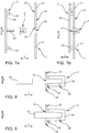
- the support grid 2 is supported in each case with a spacer 23 above and below the pin 22 against the respective cooking chamber inside 13, see for example Figures 5 . 7a and 7b ,
- the receiving plug 3 a resilient plug body 30, which consists of a silicone material such as preferably a silicone rubber.
- a pin receptacle 31 is formed as a recess which serves to receive the pin 22 of the support grid 2.
- the pin receptacle 31 facing away from the pin 22, ie in the region of the bottom of the pin receptacle 31 (right in the illustration of FIGS. 8 and 9 ), a through hole 34 which is formed to be elastically closed in the unmounted state of the pin 22 and to open by the insertion of the pin 22 in the pin receptacle 31, see, for example FIGS.
- the pin 22 facing the end of the plug body 30 is funnel-shaped and has a corresponding from the cooking chamber 11 pioneering contact surface 32 which corresponds in shape to an inclined surface 16 of a through hole 15 of the Garraummantels 12, see. eg FIGS. 7a and 7b , Behind the contact surface 32, the plug body 3 has a groove 33 which serves to hold in the passage opening 15 of the Garraummantels 12, see. eg FIGS. 5, 6 . 8 and 9 ,
- the receiving plug 3 is first inserted from the inside of the cooking chamber 13 into the through-opening 15 of the garrison casing 12, so that the receiving plug 3 with its radially smaller end region from the through-opening 15 the Garraummantels 12 protrudes.
- the receiving plug 3 can then be grasped and pulled by the user from the outside of the cooking space 14 with fingers until the contact surface 32 of the receiving stopper 3 rests against the oblique surface 16 of the passage opening 15 of the cooking enclosure 12 from the inside of the cooking chamber 13 and thereby further movement in the width Y is blocked.
- the plug body 30 has a section designed as a grip region on a end remote from the pin 22 or the cooking chamber 11. During assembly, it is possible that by pulling on the handle portion of the plug 3 is securely transferred to its mounting position. In particular, the application of the tensile force on the pin 22 or the end facing away from the cooking chamber 11 facilitates the merging of the groove 33 and the edge of the through hole 15 in the garrärmantel 12.
- the support grid 2 can be mounted by this is introduced from the cooking chamber inside 13 with the pin 22 in the pin receptacle 31 of the receiving plug 3, see for example FIGS. 7a to 8 , Since the pin 22 is radially slightly larger than the inner diameter of the pin receptacle 31 is formed, the elastic plug body 30 is radially widened by the insertion of the pin 22, see, for example FIGS. 8 and 9 , This has the effect on the one hand that the pin 22 can be frictionally held in the pin receptacle 31 by the radially inwardly acting spring force of the elastic material of the plug body 30.
- this non-positive fit is supported by the fact that in the region of the groove 33, the elastic material of the plug body 30 abuts radially outward on the edge of the through hole 15 of the Garraummantels 12 and can not escape, which can strengthen the non-positive effect in this area.
- the passage opening 34 of the stopper body 30 is widened by the insertion of the pin 22 and thus opened, so that the air can escape from the pin receptacle 31. Otherwise, the air would be compressed in the pin receptacle 31 by the insertion of the pin 22 and thereby prevent at least a complete insertion and can lead to a relaxation of the frictional Halt.
Landscapes
- Engineering & Computer Science (AREA)
- Chemical & Material Sciences (AREA)
- Combustion & Propulsion (AREA)
- Mechanical Engineering (AREA)
- General Engineering & Computer Science (AREA)
- Cookers (AREA)
- Baking, Grill, Roasting (AREA)
Applications Claiming Priority (1)
| Application Number | Priority Date | Filing Date | Title |
|---|---|---|---|
| DE102017111608.7A DE102017111608A1 (de) | 2017-05-29 | 2017-05-29 | Küchengerät |
Publications (2)
| Publication Number | Publication Date |
|---|---|
| EP3410018A1 true EP3410018A1 (fr) | 2018-12-05 |
| EP3410018B1 EP3410018B1 (fr) | 2020-04-15 |
Family
ID=62116298
Family Applications (1)
| Application Number | Title | Priority Date | Filing Date |
|---|---|---|---|
| EP18170670.6A Active EP3410018B1 (fr) | 2017-05-29 | 2018-05-03 | Tampon perforé et appareil de cuisine |
Country Status (2)
| Country | Link |
|---|---|
| EP (1) | EP3410018B1 (fr) |
| DE (1) | DE102017111608A1 (fr) |
Families Citing this family (3)
| Publication number | Priority date | Publication date | Assignee | Title |
|---|---|---|---|---|
| DE102018128475B4 (de) | 2018-11-14 | 2025-03-20 | Miele & Cie. Kg | Gargerät |
| LU103308B1 (de) * | 2024-06-04 | 2025-12-05 | Miele & Cie | Gareinrichtung |
| DE102025104835A1 (de) * | 2025-02-10 | 2026-08-13 | Miele & Cie. Kg | Gargerät mit einem an einer Verprägungskante abstützbaren Aufnahmegitter |
Citations (7)
| Publication number | Priority date | Publication date | Assignee | Title |
|---|---|---|---|---|
| US2620255A (en) * | 1951-06-12 | 1952-12-02 | Seeger Refrigerator Co | Adjustable shelf construction for refrigerator cabinets |
| FR1435106A (fr) * | 1965-02-26 | 1966-04-15 | Electro Ind & Menager Pol | Perfectionnements aux supports de clayettes pour réfrigérateurs et analogues |
| CH592848A5 (en) * | 1976-01-26 | 1977-11-15 | Elektromaschinen Ag | Baking oven for conventional and microwave heating - has enamel insulated supports for bake ware in enclosed oven |
| US4195888A (en) * | 1978-07-13 | 1980-04-01 | Magic Chef, Inc. | Mounting socket |
| EP1835232A2 (fr) * | 2006-03-16 | 2007-09-19 | Electrolux Home Products Corporation N.V. | Four de cuisson |
| WO2012152692A1 (fr) * | 2011-05-06 | 2012-11-15 | Arcelik Anonim Sirketi | Four décelant la présence d'un plateau dans la cavité de cuisson |
| DE102014109729B3 (de) * | 2014-07-11 | 2015-08-20 | Miele & Cie. Kg | Gargerät und Befestigungssystem |
Family Cites Families (2)
| Publication number | Priority date | Publication date | Assignee | Title |
|---|---|---|---|---|
| DE3505807A1 (de) | 1985-02-20 | 1986-08-21 | Licentia Patent-Verwaltungs-Gmbh, 6000 Frankfurt | Muffel fuer einen back- und bratofen |
| DE102011010149A1 (de) * | 2011-02-02 | 2012-08-02 | Fresenius Medical Care Deutschland Gmbh | Stopfen zum Verschließen und/oder Abdichten einer Öffnung in einem medizintechnischen Gerät, Behandlungsvorrichtung sowie Verfahren |
-
2017
- 2017-05-29 DE DE102017111608.7A patent/DE102017111608A1/de not_active Withdrawn
-
2018
- 2018-05-03 EP EP18170670.6A patent/EP3410018B1/fr active Active
Patent Citations (7)
| Publication number | Priority date | Publication date | Assignee | Title |
|---|---|---|---|---|
| US2620255A (en) * | 1951-06-12 | 1952-12-02 | Seeger Refrigerator Co | Adjustable shelf construction for refrigerator cabinets |
| FR1435106A (fr) * | 1965-02-26 | 1966-04-15 | Electro Ind & Menager Pol | Perfectionnements aux supports de clayettes pour réfrigérateurs et analogues |
| CH592848A5 (en) * | 1976-01-26 | 1977-11-15 | Elektromaschinen Ag | Baking oven for conventional and microwave heating - has enamel insulated supports for bake ware in enclosed oven |
| US4195888A (en) * | 1978-07-13 | 1980-04-01 | Magic Chef, Inc. | Mounting socket |
| EP1835232A2 (fr) * | 2006-03-16 | 2007-09-19 | Electrolux Home Products Corporation N.V. | Four de cuisson |
| WO2012152692A1 (fr) * | 2011-05-06 | 2012-11-15 | Arcelik Anonim Sirketi | Four décelant la présence d'un plateau dans la cavité de cuisson |
| DE102014109729B3 (de) * | 2014-07-11 | 2015-08-20 | Miele & Cie. Kg | Gargerät und Befestigungssystem |
Also Published As
| Publication number | Publication date |
|---|---|
| DE102017111608A1 (de) | 2018-11-29 |
| EP3410018B1 (fr) | 2020-04-15 |
Similar Documents
| Publication | Publication Date | Title |
|---|---|---|
| DE102010002098A1 (de) | Scharniervorrichtung, Haushaltsgerät mit einer Tür und Verfahren zum Nachrüsten eines Dämpfers | |
| EP3410018B1 (fr) | Tampon perforé et appareil de cuisine | |
| EP2406547B1 (fr) | Dispositif télescopique à glissières et moufle equipé d'un tel dispositif | |
| EP2615380B1 (fr) | Insert de compartiment de cuisson | |
| EP2615312A1 (fr) | Coussinet formé pour le stockage de élément d'appareils ménagers sur un composant d'appareil ménager, ainsi qu'appareil ménager doté d'un tel coussinet | |
| DE102018128475B4 (de) | Gargerät | |
| DE10240627A1 (de) | Trägervorrichtung, insbesondere für ein Gargerät | |
| DE102016221940A1 (de) | Haushaltsgerätevorrichtung | |
| DE102018121502A1 (de) | Gargerät, umfassend einen ersten und einen zweiten Garraum | |
| DE102022116749A1 (de) | Aufnahmegitter für ein Gargerät mit einem Garraum, Aufnahmesystem und Gargerät | |
| EP3211324B1 (fr) | Coussinet pour un appareil ménager comprenant un élément à ressort présentant une partie de recouvrement pour une ouverture d'insertion, module, appareil ménager et méthode de production d'un coussinet | |
| DE102017223100A1 (de) | Türscharnier und Haushaltsgargerät | |
| EP2314934A2 (fr) | Dispositif de réception d'un plateau de cuisson pour un appareil ménager, appareil ménager, notamment four de cuisson, doté d'un tel dispositif et procédé d'utilisation d'un tel dispositif | |
| BE1029654A1 (de) | Aufnahmegitter für ein Gargerät mit einem Garraum, Aufnahmesystem und Gargerät | |
| EP2500661A1 (fr) | Support de produit de cuisson pour un appareil de cuisson, appareil de cuisson doté d'un support de produit de cuisson correspondant, ainsi que procédé de déplacement d'un support de produit de cuisson dans un receptacle | |
| DE60005145T2 (de) | Verfahren zum heben und senken eines fritierkorbes | |
| DE202006007722U1 (de) | Kältegerät | |
| EP1656833A1 (fr) | Dispositif pour faire bouillir, rôtir ou cuire, en particulier moule de cuisson | |
| DE202020102643U1 (de) | Verschlusselement für den Zubereitungsbehälter einer Küchenmaschine, Zubereitungsbehälter und Küchenmaschine | |
| DE102024104817B4 (de) | Gargerät, vorzugsweise Dampfgargerät | |
| DE102023110462A1 (de) | Gargerät mit Teleskopschienen | |
| DE102023115191A1 (de) | Gargerät mit Teleskopschienen | |
| DE202022100454U1 (de) | Gargerät mit Teleskopauszug, Tragvorrichtung für ein Gargerät und Teleskopauszugsvorrichtung für ein Gargerät | |
| DE102017207472A1 (de) | Filtereinheit für eine Dunstabzugshaube und Dunstabzugshaube | |
| EP2615381A1 (fr) | Dispositif pour un produit de cuisson doté d'une grille et d'une cuve, agencement pour un appareil de cuisson doté d'un tel dispositif ainsi qu' un appareil de cuisson |
Legal Events
| Date | Code | Title | Description |
|---|---|---|---|
| PUAI | Public reference made under article 153(3) epc to a published international application that has entered the european phase |
Free format text: ORIGINAL CODE: 0009012 |
|
| STAA | Information on the status of an ep patent application or granted ep patent |
Free format text: STATUS: THE APPLICATION HAS BEEN PUBLISHED |
|
| AK | Designated contracting states |
Kind code of ref document: A1 Designated state(s): AL AT BE BG CH CY CZ DE DK EE ES FI FR GB GR HR HU IE IS IT LI LT LU LV MC MK MT NL NO PL PT RO RS SE SI SK SM TR |
|
| AX | Request for extension of the european patent |
Extension state: BA ME |
|
| STAA | Information on the status of an ep patent application or granted ep patent |
Free format text: STATUS: REQUEST FOR EXAMINATION WAS MADE |
|
| 17P | Request for examination filed |
Effective date: 20190605 |
|
| RBV | Designated contracting states (corrected) |
Designated state(s): AL AT BE BG CH CY CZ DE DK EE ES FI FR GB GR HR HU IE IS IT LI LT LU LV MC MK MT NL NO PL PT RO RS SE SI SK SM TR |
|
| GRAP | Despatch of communication of intention to grant a patent |
Free format text: ORIGINAL CODE: EPIDOSNIGR1 |
|
| STAA | Information on the status of an ep patent application or granted ep patent |
Free format text: STATUS: GRANT OF PATENT IS INTENDED |
|
| INTG | Intention to grant announced |
Effective date: 20200108 |
|
| GRAS | Grant fee paid |
Free format text: ORIGINAL CODE: EPIDOSNIGR3 |
|
| GRAA | (expected) grant |
Free format text: ORIGINAL CODE: 0009210 |
|
| STAA | Information on the status of an ep patent application or granted ep patent |
Free format text: STATUS: THE PATENT HAS BEEN GRANTED |
|
| AK | Designated contracting states |
Kind code of ref document: B1 Designated state(s): AL AT BE BG CH CY CZ DE DK EE ES FI FR GB GR HR HU IE IS IT LI LT LU LV MC MK MT NL NO PL PT RO RS SE SI SK SM TR |
|
| REG | Reference to a national code |
Ref country code: CH Ref legal event code: EP |
|
| REG | Reference to a national code |
Ref country code: CH Ref legal event code: NV Representative=s name: COSMOVICI INTELLECTUAL PROPERTY SARL, CH |
|
| REG | Reference to a national code |
Ref country code: DE Ref legal event code: R096 Ref document number: 502018001181 Country of ref document: DE |
|
| REG | Reference to a national code |
Ref country code: IE Ref legal event code: FG4D Free format text: LANGUAGE OF EP DOCUMENT: GERMAN |
|
| REG | Reference to a national code |
Ref country code: AT Ref legal event code: REF Ref document number: 1257752 Country of ref document: AT Kind code of ref document: T Effective date: 20200515 |
|
| REG | Reference to a national code |
Ref country code: NL Ref legal event code: FP |
|
| REG | Reference to a national code |
Ref country code: LT Ref legal event code: MG4D |
|
| PG25 | Lapsed in a contracting state [announced via postgrant information from national office to epo] |
Ref country code: IS Free format text: LAPSE BECAUSE OF FAILURE TO SUBMIT A TRANSLATION OF THE DESCRIPTION OR TO PAY THE FEE WITHIN THE PRESCRIBED TIME-LIMIT Effective date: 20200815 Ref country code: SE Free format text: LAPSE BECAUSE OF FAILURE TO SUBMIT A TRANSLATION OF THE DESCRIPTION OR TO PAY THE FEE WITHIN THE PRESCRIBED TIME-LIMIT Effective date: 20200415 Ref country code: GR Free format text: LAPSE BECAUSE OF FAILURE TO SUBMIT A TRANSLATION OF THE DESCRIPTION OR TO PAY THE FEE WITHIN THE PRESCRIBED TIME-LIMIT Effective date: 20200716 Ref country code: NO Free format text: LAPSE BECAUSE OF FAILURE TO SUBMIT A TRANSLATION OF THE DESCRIPTION OR TO PAY THE FEE WITHIN THE PRESCRIBED TIME-LIMIT Effective date: 20200715 Ref country code: FI Free format text: LAPSE BECAUSE OF FAILURE TO SUBMIT A TRANSLATION OF THE DESCRIPTION OR TO PAY THE FEE WITHIN THE PRESCRIBED TIME-LIMIT Effective date: 20200415 Ref country code: LT Free format text: LAPSE BECAUSE OF FAILURE TO SUBMIT A TRANSLATION OF THE DESCRIPTION OR TO PAY THE FEE WITHIN THE PRESCRIBED TIME-LIMIT Effective date: 20200415 Ref country code: PT Free format text: LAPSE BECAUSE OF FAILURE TO SUBMIT A TRANSLATION OF THE DESCRIPTION OR TO PAY THE FEE WITHIN THE PRESCRIBED TIME-LIMIT Effective date: 20200817 |
|
| PG25 | Lapsed in a contracting state [announced via postgrant information from national office to epo] |
Ref country code: LV Free format text: LAPSE BECAUSE OF FAILURE TO SUBMIT A TRANSLATION OF THE DESCRIPTION OR TO PAY THE FEE WITHIN THE PRESCRIBED TIME-LIMIT Effective date: 20200415 Ref country code: RS Free format text: LAPSE BECAUSE OF FAILURE TO SUBMIT A TRANSLATION OF THE DESCRIPTION OR TO PAY THE FEE WITHIN THE PRESCRIBED TIME-LIMIT Effective date: 20200415 Ref country code: HR Free format text: LAPSE BECAUSE OF FAILURE TO SUBMIT A TRANSLATION OF THE DESCRIPTION OR TO PAY THE FEE WITHIN THE PRESCRIBED TIME-LIMIT Effective date: 20200415 Ref country code: BG Free format text: LAPSE BECAUSE OF FAILURE TO SUBMIT A TRANSLATION OF THE DESCRIPTION OR TO PAY THE FEE WITHIN THE PRESCRIBED TIME-LIMIT Effective date: 20200715 |
|
| PG25 | Lapsed in a contracting state [announced via postgrant information from national office to epo] |
Ref country code: AL Free format text: LAPSE BECAUSE OF FAILURE TO SUBMIT A TRANSLATION OF THE DESCRIPTION OR TO PAY THE FEE WITHIN THE PRESCRIBED TIME-LIMIT Effective date: 20200415 |
|
| REG | Reference to a national code |
Ref country code: DE Ref legal event code: R097 Ref document number: 502018001181 Country of ref document: DE |
|
| PG25 | Lapsed in a contracting state [announced via postgrant information from national office to epo] |
Ref country code: EE Free format text: LAPSE BECAUSE OF FAILURE TO SUBMIT A TRANSLATION OF THE DESCRIPTION OR TO PAY THE FEE WITHIN THE PRESCRIBED TIME-LIMIT Effective date: 20200415 Ref country code: SM Free format text: LAPSE BECAUSE OF FAILURE TO SUBMIT A TRANSLATION OF THE DESCRIPTION OR TO PAY THE FEE WITHIN THE PRESCRIBED TIME-LIMIT Effective date: 20200415 Ref country code: IT Free format text: LAPSE BECAUSE OF FAILURE TO SUBMIT A TRANSLATION OF THE DESCRIPTION OR TO PAY THE FEE WITHIN THE PRESCRIBED TIME-LIMIT Effective date: 20200415 Ref country code: DK Free format text: LAPSE BECAUSE OF FAILURE TO SUBMIT A TRANSLATION OF THE DESCRIPTION OR TO PAY THE FEE WITHIN THE PRESCRIBED TIME-LIMIT Effective date: 20200415 Ref country code: MC Free format text: LAPSE BECAUSE OF FAILURE TO SUBMIT A TRANSLATION OF THE DESCRIPTION OR TO PAY THE FEE WITHIN THE PRESCRIBED TIME-LIMIT Effective date: 20200415 Ref country code: ES Free format text: LAPSE BECAUSE OF FAILURE TO SUBMIT A TRANSLATION OF THE DESCRIPTION OR TO PAY THE FEE WITHIN THE PRESCRIBED TIME-LIMIT Effective date: 20200415 Ref country code: CZ Free format text: LAPSE BECAUSE OF FAILURE TO SUBMIT A TRANSLATION OF THE DESCRIPTION OR TO PAY THE FEE WITHIN THE PRESCRIBED TIME-LIMIT Effective date: 20200415 Ref country code: RO Free format text: LAPSE BECAUSE OF FAILURE TO SUBMIT A TRANSLATION OF THE DESCRIPTION OR TO PAY THE FEE WITHIN THE PRESCRIBED TIME-LIMIT Effective date: 20200415 |
|
| PLBE | No opposition filed within time limit |
Free format text: ORIGINAL CODE: 0009261 |
|
| STAA | Information on the status of an ep patent application or granted ep patent |
Free format text: STATUS: NO OPPOSITION FILED WITHIN TIME LIMIT |
|
| PG25 | Lapsed in a contracting state [announced via postgrant information from national office to epo] |
Ref country code: PL Free format text: LAPSE BECAUSE OF FAILURE TO SUBMIT A TRANSLATION OF THE DESCRIPTION OR TO PAY THE FEE WITHIN THE PRESCRIBED TIME-LIMIT Effective date: 20200415 Ref country code: SK Free format text: LAPSE BECAUSE OF FAILURE TO SUBMIT A TRANSLATION OF THE DESCRIPTION OR TO PAY THE FEE WITHIN THE PRESCRIBED TIME-LIMIT Effective date: 20200415 |
|
| REG | Reference to a national code |
Ref country code: DE Ref legal event code: R084 Ref document number: 502018001181 Country of ref document: DE |
|
| 26N | No opposition filed |
Effective date: 20210118 |
|
| PG25 | Lapsed in a contracting state [announced via postgrant information from national office to epo] |
Ref country code: LU Free format text: LAPSE BECAUSE OF NON-PAYMENT OF DUE FEES Effective date: 20200503 |
|
| PG25 | Lapsed in a contracting state [announced via postgrant information from national office to epo] |
Ref country code: IE Free format text: LAPSE BECAUSE OF NON-PAYMENT OF DUE FEES Effective date: 20200503 |
|
| PG25 | Lapsed in a contracting state [announced via postgrant information from national office to epo] |
Ref country code: SI Free format text: LAPSE BECAUSE OF FAILURE TO SUBMIT A TRANSLATION OF THE DESCRIPTION OR TO PAY THE FEE WITHIN THE PRESCRIBED TIME-LIMIT Effective date: 20200415 |
|
| PG25 | Lapsed in a contracting state [announced via postgrant information from national office to epo] |
Ref country code: TR Free format text: LAPSE BECAUSE OF FAILURE TO SUBMIT A TRANSLATION OF THE DESCRIPTION OR TO PAY THE FEE WITHIN THE PRESCRIBED TIME-LIMIT Effective date: 20200415 Ref country code: MT Free format text: LAPSE BECAUSE OF FAILURE TO SUBMIT A TRANSLATION OF THE DESCRIPTION OR TO PAY THE FEE WITHIN THE PRESCRIBED TIME-LIMIT Effective date: 20200415 Ref country code: CY Free format text: LAPSE BECAUSE OF FAILURE TO SUBMIT A TRANSLATION OF THE DESCRIPTION OR TO PAY THE FEE WITHIN THE PRESCRIBED TIME-LIMIT Effective date: 20200415 |
|
| PG25 | Lapsed in a contracting state [announced via postgrant information from national office to epo] |
Ref country code: MK Free format text: LAPSE BECAUSE OF FAILURE TO SUBMIT A TRANSLATION OF THE DESCRIPTION OR TO PAY THE FEE WITHIN THE PRESCRIBED TIME-LIMIT Effective date: 20200415 |
|
| GBPC | Gb: european patent ceased through non-payment of renewal fee |
Effective date: 20220503 |
|
| PG25 | Lapsed in a contracting state [announced via postgrant information from national office to epo] |
Ref country code: GB Free format text: LAPSE BECAUSE OF NON-PAYMENT OF DUE FEES Effective date: 20220503 |
|
| P01 | Opt-out of the competence of the unified patent court (upc) registered |
Effective date: 20230528 |
|
| REG | Reference to a national code |
Ref country code: CH Ref legal event code: U11 Free format text: ST27 STATUS EVENT CODE: U-0-0-U10-U11 (AS PROVIDED BY THE NATIONAL OFFICE) Effective date: 20260601 |
|
| PGFP | Annual fee paid to national office [announced via postgrant information from national office to epo] |
Ref country code: NL Payment date: 20260519 Year of fee payment: 9 |
|
| PGFP | Annual fee paid to national office [announced via postgrant information from national office to epo] |
Ref country code: DE Payment date: 20260531 Year of fee payment: 9 |
|
| PGFP | Annual fee paid to national office [announced via postgrant information from national office to epo] |
Ref country code: AT Payment date: 20260519 Year of fee payment: 9 |
|
| PGFP | Annual fee paid to national office [announced via postgrant information from national office to epo] |
Ref country code: BE Payment date: 20260518 Year of fee payment: 9 Ref country code: CH Payment date: 20260601 Year of fee payment: 9 |
|
| PGFP | Annual fee paid to national office [announced via postgrant information from national office to epo] |
Ref country code: FR Payment date: 20260521 Year of fee payment: 9 |