EP3410026A1 - Machine extérieure et climatiseur équipé de ladite machine - Google Patents
Machine extérieure et climatiseur équipé de ladite machine Download PDFInfo
- Publication number
- EP3410026A1 EP3410026A1 EP16887860.1A EP16887860A EP3410026A1 EP 3410026 A1 EP3410026 A1 EP 3410026A1 EP 16887860 A EP16887860 A EP 16887860A EP 3410026 A1 EP3410026 A1 EP 3410026A1
- Authority
- EP
- European Patent Office
- Prior art keywords
- outdoor unit
- bell mouth
- baffle plate
- air
- disposed
- Prior art date
- Legal status (The legal status is an assumption and is not a legal conclusion. Google has not performed a legal analysis and makes no representation as to the accuracy of the status listed.)
- Granted
Links
Images


Classifications
-
- F—MECHANICAL ENGINEERING; LIGHTING; HEATING; WEAPONS; BLASTING
- F24—HEATING; RANGES; VENTILATING
- F24F—AIR-CONDITIONING; AIR-HUMIDIFICATION; VENTILATION; USE OF AIR CURRENTS FOR SCREENING
- F24F1/00—Room units for air-conditioning, e.g. separate or self-contained units or units receiving primary air from a central station
- F24F1/06—Separate outdoor units, e.g. outdoor unit to be linked to a separate room comprising a compressor and a heat exchanger
- F24F1/38—Fan details of outdoor units, e.g. bell-mouth shaped inlets or fan mountings
-
- F—MECHANICAL ENGINEERING; LIGHTING; HEATING; WEAPONS; BLASTING
- F04—POSITIVE - DISPLACEMENT MACHINES FOR LIQUIDS; PUMPS FOR LIQUIDS OR ELASTIC FLUIDS
- F04D—NON-POSITIVE-DISPLACEMENT PUMPS
- F04D29/00—Details, component parts, or accessories
- F04D29/40—Casings; Connections of working fluid
- F04D29/52—Casings; Connections of working fluid for axial pumps
- F04D29/54—Fluid-guiding means, e.g. diffusers
-
- F—MECHANICAL ENGINEERING; LIGHTING; HEATING; WEAPONS; BLASTING
- F24—HEATING; RANGES; VENTILATING
- F24F—AIR-CONDITIONING; AIR-HUMIDIFICATION; VENTILATION; USE OF AIR CURRENTS FOR SCREENING
- F24F1/00—Room units for air-conditioning, e.g. separate or self-contained units or units receiving primary air from a central station
- F24F1/06—Separate outdoor units, e.g. outdoor unit to be linked to a separate room comprising a compressor and a heat exchanger
- F24F1/40—Vibration or noise prevention at outdoor units
-
- F—MECHANICAL ENGINEERING; LIGHTING; HEATING; WEAPONS; BLASTING
- F24—HEATING; RANGES; VENTILATING
- F24F—AIR-CONDITIONING; AIR-HUMIDIFICATION; VENTILATION; USE OF AIR CURRENTS FOR SCREENING
- F24F1/00—Room units for air-conditioning, e.g. separate or self-contained units or units receiving primary air from a central station
- F24F1/06—Separate outdoor units, e.g. outdoor unit to be linked to a separate room comprising a compressor and a heat exchanger
- F24F1/46—Component arrangements in separate outdoor units
- F24F1/48—Component arrangements in separate outdoor units characterised by air airflow, e.g. inlet or outlet airflow
- F24F1/54—Inlet and outlet arranged on opposite sides
Definitions
- the present invention relates to an outdoor unit and an air conditioner including the same, and in particular to an outdoor unit including an axial-flow fan and an air conditioner including such an outdoor unit.
- an axial-flow fan is attached to deliver air into the heat exchanger.
- a bell mouth is provided around an outer circumference of the axial-flow fan.
- an upper baffle plate is provided above the axial-flow fan, and a lower baffle plate is provided below the axial-flow fan.
- the upper baffle plate and the lower baffle plate are disposed from the heat exchanger toward the bell mouth.
- PTD 1 is an exemplary patent document which discloses such an outdoor unit.
- the present invention has been made as part of development thereof.
- One object of the present invention is to provide an outdoor unit which achieves further reduction in ventilation resistance, and another object of the present invention is to provide an air conditioner including such an outdoor unit.
- An outdoor unit in accordance with the present invention includes a casing, a heat exchanger, a blowing unit, a bell mouth, and a baffle plate.
- the casing includes a first wall portion having an air inlet, and a second wall portion having an air outlet.
- the heat exchanger is disposed in the casing to face the air inlet.
- the blowing unit includes an axial-flow fan disposed between the heat exchanger and the second wall portion.
- the bell mouth is disposed on an inner surface of the second wall portion to communicate with the air outlet and circumferentially surround the axial-flow fan.
- the baffle plate is attached to a position on the inner surface of the second wall portion and disposed to incline from the position toward where the bell mouth is disposed.
- An air conditioner in accordance with the present invention is an air conditioner including the outdoor unit according to claim 1.
- the baffle plate is attached to a position on the inner surface of the second wall portion and disposed to incline from the position toward where the bell mouth is disposed.
- air passing through the heat exchanger and colliding with the second wall portion flows along the baffle plate and is guided to the bell mouth.
- ventilation resistance in the outdoor unit can be reduced, and noise of the outdoor unit can be reduced.
- the air conditioner in accordance with the present invention includes the outdoor unit according to claim 1, ventilation resistance in the outdoor unit can be reduced, and efficiency of heat exchange in the outdoor unit can be increased.
- an air conditioner 1 includes a compressor 3, a four-way valve 5, an indoor unit 7, a throttle device 9, and an outdoor unit 11.
- Compressor 3, four-way valve 5, indoor unit 7, throttle device 9, and outdoor unit 11 are connected by a refrigerant pipe.
- the high-pressure liquid refrigerant delivered from outdoor unit 11 turns into refrigerant in a two-phase state including low-pressure gas refrigerant and liquid refrigerant.
- the refrigerant in the two-phase state flows into indoor unit 7.
- indoor unit 7 heat exchange is performed between the refrigerant in the two-phase state flowing therein and air delivered into indoor unit 7, the liquid refrigerant evaporates, and thus the refrigerant in the two-phase state turns into low-pressure gas refrigerant (single phase).
- the interior of a room is cooled by this heat exchange.
- the low-pressure gas refrigerant delivered from indoor unit 7 flows into compressor 3 via four-way valve 5, is compressed into high-temperature high-pressure gas refrigerant, and is discharged again from compressor 3. This cycle is repeated thereafter.
- the refrigerant in the two-phase state flows into outdoor unit 11.
- outdoor unit 11 heat exchange is performed between the refrigerant in the two-phase state flowing therein and air delivered into outdoor unit 11, the liquid refrigerant evaporates, and thus the refrigerant in the two-phase state turns into low-pressure gas refrigerant (single phase).
- the low-pressure gas refrigerant delivered from outdoor unit 11 flows into compressor 3 via four-way valve 5, is compressed into high-temperature high-pressure gas refrigerant, and is discharged again from compressor 3. This cycle is repeated thereafter.
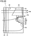
- a heat exchanger 23 As shown in Figs. 2 and 3 , a heat exchanger 23, an axial-flow fan 25, a bell mouth 27, and a fan motor 29 are disposed in a casing 21 of outdoor unit 11.
- Casing 21 includes a front panel 33 (second wall portion) and a rear panel 35 (first wall portion).
- Rear panel 35 is provided with an air inlet 21a for introducing air into casing 21.
- Front panel 33 is provided with an air outlet 21b for exhausting the air introduced into casing 21. It should be noted that front panel 33 and rear panel 35 may be formed as separate elements, or may be integrally formed as casing 21.
- Heat exchanger 23 is disposed to face air inlet 21a.
- Axial-flow fan 25 and fan motor 29 are disposed between heat exchanger 23 and front panel 33.
- Fan motor 29 is fixed to a motor support 31.
- Bell mouth 27 and a baffle plate 37 are disposed on an inner surface (inner side) of front panel 33.
- Bell mouth 27 is disposed to circumferentially surround axial-flow fan 25.
- Bell mouth 27 has a first opening 27a opened toward heat exchanger 23, and a second opening 27b opened toward air outlet 21b. Second opening 27b communicates with air outlet 21a.
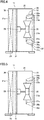
- Baffle plate 37 is attached to a predetermined position on the inner surface of front panel 33 spaced from bell mouth 27, and is disposed to incline from that position toward where bell mouth 27 is disposed. Further, baffle plate 37 includes a portion extending from the predetermined position on the inner surface of front panel 33 spaced from an outer circumferential end 28b of second opening 27b in a radial direction of axial-flow fan 25, toward an outer circumferential end 28a of first opening 27a of bell mouth 27. It should be noted that substantive baffle plate 37 shown in Fig. 2 is an example, and the baffle plate is not limited to this baffle plate 37.
- baffle plate 37 of outdoor unit 11 will be described in each embodiment. It should be noted that, in each drawing of each embodiment, members identical to those shown in Figs. 2 and 3 will be designated by the same reference numerals, and the description thereof will not be repeated, unless otherwise required.
- baffle plate 37 is attached to a predetermined position on the inner surface of front panel 33 spaced from outer circumferential end 28b of second opening 27b, and is disposed to incline from that position toward outer circumferential end 28a of first opening 27a of bell mouth 27.
- Baffle plate 37 includes an attached portion 37a and an inclined portion 37b. Attached portion 37a is fixed to the inner surface of front panel 33. Inclined portion 37b is disposed at a predetermined angle with respect to attached portion 37a.
- a distance (height) from the inner surface of front panel 33 to an end portion of baffle plate 37 closer to heat exchanger 23 is set to be substantially the same as a distance (height) from the inner surface of front panel 33 to outer circumferential end 28a of bell mouth 27.
- baffle plate 37 is formed as an element separate from bell mouth 27, and they are disposed as separate parts on front panel 33.
- baffle plate 37 is disposed from front panel 33 toward outer circumferential end 28a of bell mouth 27, ventilation resistance can be suppressed and noise can be reduced. This will be described in comparison with an outdoor unit in accordance with a comparative example.
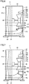
- outdoor unit 11 in accordance with the comparative example has the same structure as that of outdoor unit 11 shown in Fig. 4 except that no baffle plate is disposed. Accordingly, members identical to those shown in Fig. 4 will be designated by the same reference numerals, and the description thereof will not be repeated, unless otherwise required.
- a flow of air concentrates on the inner surface of front panel 33 and the outer wall of bell mouth 27, and the air flows faster.
- the air (flow) separates at the outer wall close to first opening 27a of bell mouth 27 (see an arrow FD).
- the air separated from the outer wall of bell mouth 27 is influenced by the shape of bell mouth 27 and by air suction by axial-flow fan 25, and flows toward heat exchanger 23 as a backflow.
- the baffle plate is attached to the predetermined position on the inner surface of front panel 33, and is disposed to incline from that position toward outer circumferential end 28a of bell mouth 27 (see Fig. 4 ).
- ventilation resistance caused by the separation of the air (flow) can be reduced.
- efficiency of heat exchange in outdoor unit 11 can be increased, and noise of outdoor unit 11 can be reduced.
- baffle plate 37 is disposed to incline from the predetermined position on the inner surface of front panel 33 toward outer circumferential end 28a of bell mouth 27. This does not obstruct a flow of air from air inlet 21a toward heat exchanger 23, and causes no increase in ventilation resistance due to obstruction of the flow of air.
- baffle plate 37 of outdoor unit 11 in accordance with the first embodiment is formed as an element separate from bell mouth 27. This facilitates manufacturing and can contribute to reduction of manufacturing cost, when compared with a case where a baffle plate and a bell mouth having a complicated shape are formed by integral molding.
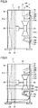
- bell mouth 27 and baffle plate 37 are disposed on the inner surface of front panel 33.
- a distance HA (height) from the inner surface of front panel 33 to the end portion of baffle plate 37 closer to heat exchanger 23 is set to be longer than a distance HB (height) from the inner surface of front panel 33 to outer circumferential end 28a of first opening 27a of bell mouth 27.
- a distance (difference in height: HA-HB) from outer circumferential end 28a of bell mouth 27 to the end portion of baffle plate 37 closer to heat exchanger 23 is about 30 mm to 50 mm, for example.
- An upper limit value of this distance should be set to a distance at which a flow of air is not obstructed by baffle plate 37 itself.
- a lower limit value of this distance should be set to a distance which allows air flowing backward to flow between the outer wall of bell mouth 27 and baffle plate 37, as described below.
- the height (distance HA) of baffle plate 37 is set to be greater than the height (distance HB) of the bell mouth.
- baffle plates 37 are disposed above and below bell mouth 27 to sandwich bell mouth 27 from above and below directions.
- baffle plates 37 are disposed to the right and left of bell mouth 27 to sandwich bell mouth 27 from right and left directions.
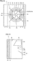
- heat exchanger 23 is disposed from the rear panel 35 side toward a side panel side of casing 21 in order to improve heat exchange performance.
- air passing through a portion of the heat exchanger located on the side panel side (a heat exchanger 23a) attempts to flow toward the outer wall (outer peripheral surface) of bell mouth 27.
- baffle plate 37 is disposed between bell mouth 27 and heat exchanger 23a located on the side panel side. Accordingly, as shown in Fig. 12 , air passing through heat exchanger 23a located on the side panel side (air A: arrows FS) and air passing through a portion of heat exchanger 23 located on the rear panel 35 side (air B: arrows FT) collide with front panel 33, and then flow along baffle plate 37. Air A and air B flowing along baffle plate 37 are exhausted out of casing 21 via bell mouth 27 and air outlet 21b.
- baffle plate 37 is disposed with respect to bell mouth 27 in outdoor unit 11 described above.
- outdoor unit 11 also having heat exchanger 23 disposed on the side panel side (heat exchanger 23a), taking the flow of the air passing through heat exchanger 23a described above into consideration, it is desirable to dispose baffle plate 37 at least between bell mouth 27 and heat exchanger 23a located on the side panel side.
- baffle plates 37 are disposed above and below bell mouth 27 to sandwich circular bell mouth 27 from above and below directions.
- baffle plates 37 are disposed parallel to a tangent at a position of outer circumferential end 28a of bell mouth 27 where baffle plate 37 is closest to bell mouth 27. Further, a length LA of baffle plate 37 is set to a length which does not exceed a diameter LB of bell mouth 27 at outer circumferential end 28a.
- length LA of baffle plate 37 is desirably a length which does not exceed diameter LB.
- length LA of baffle plate 37 is desirably more than or equal to 10% of diameter LB.
- length LA of baffle plate 37 is set to a relatively long length in a range in which it does not exceed diameter LB of bell mouth 27 at outer circumferential end 28a.
- the ventilation resistance can be reduced.
- efficiency of heat exchange in outdoor unit 11 can be increased, and noise of outdoor unit 11 can be reduced.
- baffle plates 37 are disposed above and below bell mouth 27 to sandwich circular bell mouth 27 from above and below directions.
- Each of baffle plates 37 is disposed in an arc-like manner along outer circumferential end 28a of bell mouth 27.
- each of baffle plates 37 is disposed in an arc-like manner along outer circumferential end 28a of bell mouth 27, the spacing between baffle plate 37 and outer circumferential end 28a of bell mouth 27 is substantially constant.
- the flow of the air flowing from baffle plate 37 to first opening 27a of bell mouth 27 is more stabilized with respect to a circumferential direction of bell mouth 27.
- baffle plate 37 can be dispose over more than or equal to 10% of an entire circumference of bell mouth 27.
- ring-shaped baffle plate 37 is disposed to circumferentially surround circular bell mouth 27.
- the ventilation resistance can be reliably reduced.
- efficiency of heat exchange in outdoor unit 11 can be reliably increased, and noise of outdoor unit 11 can also be reliably reduced.
- baffle plate 37 extending in one direction, baffle plate 37 extending in an arc-like manner, and ring-shaped baffle plate 37 have been described as examples of baffle plate 37.
- variations of the sectional shape of baffle plate 37 will be described.
- the sectional shape is a sectional shape in a direction substantially orthogonal to a direction in which baffle plate 37 extends.
- baffle plate 37 including attached portion 37a and inclined portion 37b has been described as an example.
- attached portion 37a and inclined portion 37b each linearly extend, and inclined portion 37b is disposed at a predetermined angle with respect to attached portion 37a.
- the air colliding with front panel 33 can be suppressed from attempting to flow along the outer wall (outer peripheral surface) of bell mouth 27.
- the ventilation resistance can be reduced. Since the ventilation resistance is reduced, efficiency of heat exchange in outdoor unit 11 can be increased, and noise of outdoor unit 11 can also be reduced.
- baffle plate 37 is processed relatively easily, and baffle plate 37 can be easily manufactured.
- baffle plate 37 includes attached portion 37a, inclined portion 37b, and a curved portion 37c.
- Curved portion 37c is disposed between attached portion 37a and inclined portion 37b.
- Curved portion 37c is formed to protrude toward front panel 33.
- Curved portion 37c smoothly connects attached portion 37a and inclined portions 37b disposed at a predetermined angle with respect to attached portion 37a.
- the ventilation resistance can be further reduced, when compared with a case where an air flow angle changes sharply.
- efficiency of heat exchange in outdoor unit 11 can be increased, and noise of outdoor unit 11 can also be reduced.
- baffle plate 37 includes attached portion 37a, inclined portion 37b, and a curved portion 37d.
- Curved portion 37d is formed to protrude toward heat exchanger 23.
- Curved portion 37d is formed from inclined portion 37b toward outer circumferential end 28a of bell mouth 27. Outer circumferential end 28a is located on an extension line of a tangent at an end of curved portion 37d.
- curved portion 37d is curved from inclined portion 37b toward outer circumferential end 28a of bell mouth 27, the air which attempts to flow into first opening 27a of bell mouth 27 via curved portion 37d easily flows along an inner wall (inner circumferential surface) of bell mouth 27.
- the ventilation resistance can be further reduced, when compared with a case where no curved portion 37d is formed.
- efficiency of heat exchange in outdoor unit 11 can be increased, and noise of outdoor unit 11 can also be reduced.
- baffle plate 37 includes attached portion 37a, curved portion 37c, inclined portion 37b, and curved portion 37d.
- Curved portion 37c is formed to protrude toward front panel 33 for smoothly connecting attached portion 37a and inclined portions 37b.
- Curved portion 37d is formed to protrude toward heat exchanger 23, and is formed from inclined portion 37b toward outer circumferential end 28a of bell mouth 27.
- the ventilation resistance can be furthermore reduced, when compared with the case where the air flow angle changes sharply and the case where no curved portion 37d is formed.
- efficiency of heat exchange in outdoor unit 11 can be increased, and noise of outdoor unit 11 can also be reduced.
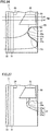
- baffle plate 37 includes attached portion 37a, inclined portion 37b, and a curved portion 37e.
- Curved portion 37e is formed in an arc-like manner to protrude toward heat exchanger 23.
- Curved portion 37e is formed to cover outer circumferential end 28a of first opening 27a of bell mouth 27 from inclined portion 37b.
- a vent 45 is formed in curved portion 37e.
- Rotation of axial-flow fan 25 produces a flow in an axial direction (axial component), and a flow in a radial direction (radial component) caused by a centrifugal force associated with the rotation of axial-flow fan 25. Air as a vector with the axial component and the radial component is blown out from bell mouth 27.
- frost may stick to heat exchanger 23 depending on the operation state of the air conditioner.
- the amount of air passing through heat exchanger 23 is reduced, and the flow in the axial direction (arrow VM) is relatively weak with respect to the flow in the radial direction (arrow VR).
- an actual flow (arrow VA) obtained by combining the flow in the axial direction (arrow VM) and the flow in radial direction (arrow VR) may include a flow toward the inner wall (inner circumferential surface) of bell mouth 27 (casing 21). Due to this flow of air, air flows back toward heat exchanger 23 (see arrow FC) at the inner wall (inner circumferential surface) of bell mouth 27.
- curved portion 37e is formed to cover outer circumferential end 28a of first opening 27a of bell mouth 27. Vent 45 is formed in curved portion 37e.
- the present invention is effectively applicable to an outdoor unit including an axial-flow fan, and an air conditioner including the outdoor unit.
Landscapes
- Engineering & Computer Science (AREA)
- Mechanical Engineering (AREA)
- General Engineering & Computer Science (AREA)
- Chemical & Material Sciences (AREA)
- Combustion & Propulsion (AREA)
- Other Air-Conditioning Systems (AREA)
Applications Claiming Priority (1)
| Application Number | Priority Date | Filing Date | Title |
|---|---|---|---|
| PCT/JP2016/051999 WO2017130273A1 (fr) | 2016-01-25 | 2016-01-25 | Machine extérieure et climatiseur équipé de ladite machine |
Publications (3)
| Publication Number | Publication Date |
|---|---|
| EP3410026A1 true EP3410026A1 (fr) | 2018-12-05 |
| EP3410026A4 EP3410026A4 (fr) | 2019-01-02 |
| EP3410026B1 EP3410026B1 (fr) | 2023-06-07 |
Family
ID=59397508
Family Applications (1)
| Application Number | Title | Priority Date | Filing Date |
|---|---|---|---|
| EP16887860.1A Active EP3410026B1 (fr) | 2016-01-25 | 2016-01-25 | Machine extérieure et climatiseur équipé de ladite machine |
Country Status (7)
| Country | Link |
|---|---|
| US (1) | US11054156B2 (fr) |
| EP (1) | EP3410026B1 (fr) |
| JP (1) | JP6680806B2 (fr) |
| KR (1) | KR102163905B1 (fr) |
| CN (1) | CN108474570B (fr) |
| AU (1) | AU2016389531B2 (fr) |
| WO (1) | WO2017130273A1 (fr) |
Families Citing this family (5)
| Publication number | Priority date | Publication date | Assignee | Title |
|---|---|---|---|---|
| JP6504591B1 (ja) * | 2018-03-19 | 2019-04-24 | 三菱電機株式会社 | 冷却構造及び冷却構造を備えた室外ユニット |
| JP7262578B2 (ja) * | 2019-05-24 | 2023-04-21 | 三菱電機株式会社 | 室外機および冷凍サイクル装置 |
| JP7051764B2 (ja) * | 2019-08-07 | 2022-04-11 | ダイキン工業株式会社 | 冷凍装置の熱源ユニット |
| JP7173939B2 (ja) * | 2019-08-26 | 2022-11-16 | ダイキン工業株式会社 | 送風装置及びヒートポンプユニット |
| WO2021084605A1 (fr) * | 2019-10-29 | 2021-05-06 | 三菱電機株式会社 | Unité extérieure pour dispositif de climatisation |
Family Cites Families (45)
| Publication number | Priority date | Publication date | Assignee | Title |
|---|---|---|---|---|
| JPS5753976Y2 (fr) * | 1977-11-05 | 1982-11-22 | ||
| JPS59142677U (ja) * | 1983-03-14 | 1984-09-22 | 三洋電機株式会社 | 熱交換ユニツト |
| JPH0648251Y2 (ja) * | 1988-06-08 | 1994-12-12 | ダイキン工業株式会社 | 空気調和機の吹出口構造 |
| US5248224A (en) * | 1990-12-14 | 1993-09-28 | Carrier Corporation | Orificed shroud for axial flow fan |
| JP2707861B2 (ja) | 1991-03-06 | 1998-02-04 | 三菱電機株式会社 | 空気調和機の室外ユニット |
| JPH05106871A (ja) * | 1991-04-25 | 1993-04-27 | Matsushita Refrig Co Ltd | セパレート型空気調和機の室外機 |
| JP2524186Y2 (ja) * | 1991-05-30 | 1997-01-29 | ダイキン工業株式会社 | 空気調和装置の室外機 |
| JPH1094832A (ja) | 1996-09-24 | 1998-04-14 | Nishizawa Kogyo:Kk | 板金プレス成形方法および板金プレス装置 |
| JP3057259U (ja) * | 1998-09-03 | 1999-04-09 | トキワ工業株式会社 | 柔軟性ダイス |
| KR100408781B1 (ko) * | 1999-08-09 | 2003-12-06 | 다이킨 고교 가부시키가이샤 | 송풍유닛의 팬 가드 및 공기조화장치 |
| JP4190683B2 (ja) * | 1999-11-22 | 2008-12-03 | 株式会社小松製作所 | ファン装置 |
| JP2003184797A (ja) * | 2001-12-14 | 2003-07-03 | Daikin Ind Ltd | 送風装置及び該送風装置を備えた空気調和機 |
| JP2004150654A (ja) | 2002-10-29 | 2004-05-27 | Matsushita Electric Ind Co Ltd | 空気調和機の室外機 |
| JP2004211931A (ja) | 2002-12-27 | 2004-07-29 | Daikin Ind Ltd | 空気調和機用室外機 |
| JP2005114231A (ja) * | 2003-10-07 | 2005-04-28 | Matsushita Electric Ind Co Ltd | 空気調和機の室外機 |
| JP4690682B2 (ja) * | 2004-09-07 | 2011-06-01 | 三菱電機株式会社 | 空調機 |
| JP4682635B2 (ja) | 2005-02-07 | 2011-05-11 | 株式会社富士通ゼネラル | 空気調和機の室外機 |
| US7481619B2 (en) * | 2005-08-11 | 2009-01-27 | York International Corporation | Extended venturi fan ring |
| KR20080062891A (ko) * | 2006-12-29 | 2008-07-03 | 엘지전자 주식회사 | 공기조화기의 팬 |
| US8221074B2 (en) * | 2007-12-21 | 2012-07-17 | Paccar Inc | Fan ring shroud assembly |
| KR20090076031A (ko) * | 2008-01-07 | 2009-07-13 | 삼성전자주식회사 | 송풍장치 및 이를 구비하는 공기조화기의 실외기 |
| EP2085709A1 (fr) * | 2008-01-30 | 2009-08-05 | LG Electronics Inc. | Climatiseur |
| CN101925783B (zh) * | 2008-03-11 | 2013-07-17 | 三菱电机株式会社 | 空气调节机 |
| WO2009130954A1 (fr) * | 2008-04-22 | 2009-10-29 | 三菱電機株式会社 | Soufflante et dispositif de pompe à chaleur l'utilisant |
| JP4823294B2 (ja) * | 2008-11-04 | 2011-11-24 | 三菱電機株式会社 | 送風機及びこの送風機を用いたヒートポンプ装置 |
| JP2010127590A (ja) * | 2008-12-01 | 2010-06-10 | Mitsubishi Electric Corp | 空気調和機の室外機及びこの室外機を備えた空気調和機 |
| JP5289200B2 (ja) * | 2009-06-19 | 2013-09-11 | 三菱電機株式会社 | 空気調和機用室外機 |
| JP5418306B2 (ja) | 2010-03-03 | 2014-02-19 | パナソニック株式会社 | 空気調和機 |
| JP5240239B2 (ja) * | 2010-06-03 | 2013-07-17 | 三菱電機株式会社 | 冷凍サイクル装置の室外機 |
| WO2012035577A1 (fr) * | 2010-09-14 | 2012-03-22 | 三菱電機株式会社 | Soufflante pour unité extérieure, unité extérieure et dispositif à cycle de réfrigération |
| JP2013044481A (ja) * | 2011-08-25 | 2013-03-04 | Panasonic Corp | ヒートポンプ装置の室外ユニット |
| JP5558449B2 (ja) * | 2011-10-03 | 2014-07-23 | 三菱電機株式会社 | 送風機、室外機及び冷凍サイクル装置 |
| JP2013096622A (ja) | 2011-10-31 | 2013-05-20 | Daikin Industries Ltd | 空気調和装置の室外ユニット |
| WO2013094082A1 (fr) * | 2011-12-19 | 2013-06-27 | 三菱電機株式会社 | Unité extérieure et dispositif de cycle de réfrigération avec unité extérieure |
| JP2014031976A (ja) * | 2012-08-06 | 2014-02-20 | Mitsubishi Heavy Ind Ltd | 空気調和機の室外機ユニット |
| JP5805598B2 (ja) * | 2012-09-12 | 2015-11-04 | 三菱電機株式会社 | 冷凍サイクル装置 |
| CN105008723B (zh) * | 2013-02-22 | 2017-08-15 | 日立空调·家用电器株式会社 | 螺旋桨式风机及具备该螺旋桨式风机的空调机 |
| JP5984782B2 (ja) * | 2013-11-07 | 2016-09-06 | 三菱電機株式会社 | 空気調和機の室外機 |
| JP5984781B2 (ja) * | 2013-11-07 | 2016-09-06 | 三菱電機株式会社 | 空気調和機の室外機 |
| CN203731634U (zh) * | 2013-12-10 | 2014-07-23 | 昆山市言兴净化设备有限公司 | 一种一体化高效送风口 |
| JP6223232B2 (ja) * | 2014-03-03 | 2017-11-01 | 三菱電機株式会社 | 室外機 |
| CN104374010B (zh) * | 2014-10-27 | 2018-02-09 | 珠海格力电器股份有限公司 | 落地式空调器 |
| CN204787121U (zh) * | 2015-05-25 | 2015-11-18 | 珠海格力电器股份有限公司 | 风道组件及空调器 |
| CN105202732B (zh) * | 2015-10-23 | 2018-03-20 | 珠海格力电器股份有限公司 | 一种整流结构及具有该结构的空调柜机 |
| JP6849938B2 (ja) * | 2016-05-31 | 2021-03-31 | 株式会社富士通ゼネラル | 空気調和機の室外機 |
-
2016
- 2016-01-25 KR KR1020187017785A patent/KR102163905B1/ko not_active Expired - Fee Related
- 2016-01-25 CN CN201680078555.5A patent/CN108474570B/zh not_active Expired - Fee Related
- 2016-01-25 US US15/779,925 patent/US11054156B2/en not_active Expired - Fee Related
- 2016-01-25 JP JP2017563415A patent/JP6680806B2/ja not_active Expired - Fee Related
- 2016-01-25 AU AU2016389531A patent/AU2016389531B2/en not_active Ceased
- 2016-01-25 WO PCT/JP2016/051999 patent/WO2017130273A1/fr not_active Ceased
- 2016-01-25 EP EP16887860.1A patent/EP3410026B1/fr active Active
Also Published As
| Publication number | Publication date |
|---|---|
| KR20180086472A (ko) | 2018-07-31 |
| KR102163905B1 (ko) | 2020-10-12 |
| CN108474570A (zh) | 2018-08-31 |
| US20180363928A1 (en) | 2018-12-20 |
| WO2017130273A1 (fr) | 2017-08-03 |
| EP3410026B1 (fr) | 2023-06-07 |
| JP6680806B2 (ja) | 2020-04-15 |
| US11054156B2 (en) | 2021-07-06 |
| CN108474570B (zh) | 2020-10-16 |
| EP3410026A4 (fr) | 2019-01-02 |
| AU2016389531A1 (en) | 2018-07-05 |
| JPWO2017130273A1 (ja) | 2018-10-25 |
| AU2016389531B2 (en) | 2019-07-18 |
Similar Documents
| Publication | Publication Date | Title |
|---|---|---|
| EP3333431B1 (fr) | Soufflante centrifuge, dispositif de climatisation, et dispositif à cycle de réfrigération | |
| EP3410026B1 (fr) | Machine extérieure et climatiseur équipé de ladite machine | |
| KR101812014B1 (ko) | 공기조화기용 송풍기 | |
| EP3736450B1 (fr) | Soufflante centrifuge, appareil de soufflage d'air, appareil de conditionnement d'air et appareil à cycle de réfrigération | |
| US9995303B2 (en) | Air conditioner | |
| EP3372839B1 (fr) | Soufflante, unité extérieure, et appareil à cycle de réfrigération | |
| EP3321512B1 (fr) | Soufflante, et dispositif de conditionnement d'air | |
| EP3070410B1 (fr) | Unité extérieure pour climatiseur | |
| US9874227B2 (en) | Air blower and outdoor unit | |
| US11542955B2 (en) | Diagonal fan having an optimized diagonal impeller | |
| US12006947B2 (en) | Diagonal fan with outlet guide vane device | |
| EP3460254B1 (fr) | Climatiseur | |
| US20150354584A1 (en) | Centrifugal fan | |
| CN110088482A (zh) | 多翼送风机 | |
| KR101996052B1 (ko) | 공기조화기 | |
| JP7282215B2 (ja) | 送風機及び空気調和装置 | |
| JP7019619B2 (ja) | 遠心送風機 | |
| EP4180668A1 (fr) | Compresseur multi-étages avec nervures réduisant le tourbillon | |
| EP3916238A1 (fr) | Ventilateur de soufflante, unité intérieure, et climatiseur | |
| EP4431747A1 (fr) | Ventilateur à flux transversal, dispositif de soufflage et dispositif à cycle de réfrigération | |
| EP3534015B1 (fr) | Ventilateur à hélice, machine extérieure et appareil à cycle de réfrigération | |
| JP2009013923A (ja) | 遠心式送風機 | |
| CN217004667U (zh) | 空调器室内机 | |
| US20200063748A1 (en) | Centrifugal blower and method of assembling the same | |
| JP7555474B2 (ja) | 送風装置および空気調和装置 |
Legal Events
| Date | Code | Title | Description |
|---|---|---|---|
| STAA | Information on the status of an ep patent application or granted ep patent |
Free format text: STATUS: THE INTERNATIONAL PUBLICATION HAS BEEN MADE |
|
| PUAI | Public reference made under article 153(3) epc to a published international application that has entered the european phase |
Free format text: ORIGINAL CODE: 0009012 |
|
| STAA | Information on the status of an ep patent application or granted ep patent |
Free format text: STATUS: REQUEST FOR EXAMINATION WAS MADE |
|
| 17P | Request for examination filed |
Effective date: 20180620 |
|
| AK | Designated contracting states |
Kind code of ref document: A1 Designated state(s): AL AT BE BG CH CY CZ DE DK EE ES FI FR GB GR HR HU IE IS IT LI LT LU LV MC MK MT NL NO PL PT RO RS SE SI SK SM TR |
|
| AX | Request for extension of the european patent |
Extension state: BA ME |
|
| A4 | Supplementary search report drawn up and despatched |
Effective date: 20181130 |
|
| RIC1 | Information provided on ipc code assigned before grant |
Ipc: F24F 1/40 20110101ALI20181126BHEP Ipc: F24F 1/54 20110101ALI20181126BHEP Ipc: F24F 1/38 20110101AFI20181126BHEP |
|
| DAV | Request for validation of the european patent (deleted) | ||
| DAX | Request for extension of the european patent (deleted) | ||
| STAA | Information on the status of an ep patent application or granted ep patent |
Free format text: STATUS: EXAMINATION IS IN PROGRESS |
|
| 17Q | First examination report despatched |
Effective date: 20200924 |
|
| GRAP | Despatch of communication of intention to grant a patent |
Free format text: ORIGINAL CODE: EPIDOSNIGR1 |
|
| STAA | Information on the status of an ep patent application or granted ep patent |
Free format text: STATUS: GRANT OF PATENT IS INTENDED |
|
| INTG | Intention to grant announced |
Effective date: 20221216 |
|
| GRAS | Grant fee paid |
Free format text: ORIGINAL CODE: EPIDOSNIGR3 |
|
| GRAA | (expected) grant |
Free format text: ORIGINAL CODE: 0009210 |
|
| STAA | Information on the status of an ep patent application or granted ep patent |
Free format text: STATUS: THE PATENT HAS BEEN GRANTED |
|
| AK | Designated contracting states |
Kind code of ref document: B1 Designated state(s): AL AT BE BG CH CY CZ DE DK EE ES FI FR GB GR HR HU IE IS IT LI LT LU LV MC MK MT NL NO PL PT RO RS SE SI SK SM TR |
|
| REG | Reference to a national code |
Ref country code: GB Ref legal event code: FG4D |
|
| P01 | Opt-out of the competence of the unified patent court (upc) registered |
Effective date: 20230508 |
|
| REG | Reference to a national code |
Ref country code: CH Ref legal event code: EP Ref country code: AT Ref legal event code: REF Ref document number: 1576161 Country of ref document: AT Kind code of ref document: T Effective date: 20230615 Ref country code: DE Ref legal event code: R096 Ref document number: 602016080222 Country of ref document: DE |
|
| REG | Reference to a national code |
Ref country code: LT Ref legal event code: MG9D |
|
| REG | Reference to a national code |
Ref country code: NL Ref legal event code: MP Effective date: 20230607 |
|
| PG25 | Lapsed in a contracting state [announced via postgrant information from national office to epo] |
Ref country code: SE Free format text: LAPSE BECAUSE OF FAILURE TO SUBMIT A TRANSLATION OF THE DESCRIPTION OR TO PAY THE FEE WITHIN THE PRESCRIBED TIME-LIMIT Effective date: 20230607 Ref country code: NO Free format text: LAPSE BECAUSE OF FAILURE TO SUBMIT A TRANSLATION OF THE DESCRIPTION OR TO PAY THE FEE WITHIN THE PRESCRIBED TIME-LIMIT Effective date: 20230907 Ref country code: ES Free format text: LAPSE BECAUSE OF FAILURE TO SUBMIT A TRANSLATION OF THE DESCRIPTION OR TO PAY THE FEE WITHIN THE PRESCRIBED TIME-LIMIT Effective date: 20230607 |
|
| REG | Reference to a national code |
Ref country code: AT Ref legal event code: MK05 Ref document number: 1576161 Country of ref document: AT Kind code of ref document: T Effective date: 20230607 |
|
| PG25 | Lapsed in a contracting state [announced via postgrant information from national office to epo] |
Ref country code: RS Free format text: LAPSE BECAUSE OF FAILURE TO SUBMIT A TRANSLATION OF THE DESCRIPTION OR TO PAY THE FEE WITHIN THE PRESCRIBED TIME-LIMIT Effective date: 20230607 Ref country code: NL Free format text: LAPSE BECAUSE OF FAILURE TO SUBMIT A TRANSLATION OF THE DESCRIPTION OR TO PAY THE FEE WITHIN THE PRESCRIBED TIME-LIMIT Effective date: 20230607 Ref country code: LV Free format text: LAPSE BECAUSE OF FAILURE TO SUBMIT A TRANSLATION OF THE DESCRIPTION OR TO PAY THE FEE WITHIN THE PRESCRIBED TIME-LIMIT Effective date: 20230607 Ref country code: LT Free format text: LAPSE BECAUSE OF FAILURE TO SUBMIT A TRANSLATION OF THE DESCRIPTION OR TO PAY THE FEE WITHIN THE PRESCRIBED TIME-LIMIT Effective date: 20230607 Ref country code: HR Free format text: LAPSE BECAUSE OF FAILURE TO SUBMIT A TRANSLATION OF THE DESCRIPTION OR TO PAY THE FEE WITHIN THE PRESCRIBED TIME-LIMIT Effective date: 20230607 Ref country code: GR Free format text: LAPSE BECAUSE OF FAILURE TO SUBMIT A TRANSLATION OF THE DESCRIPTION OR TO PAY THE FEE WITHIN THE PRESCRIBED TIME-LIMIT Effective date: 20230908 |
|
| PG25 | Lapsed in a contracting state [announced via postgrant information from national office to epo] |
Ref country code: FI Free format text: LAPSE BECAUSE OF FAILURE TO SUBMIT A TRANSLATION OF THE DESCRIPTION OR TO PAY THE FEE WITHIN THE PRESCRIBED TIME-LIMIT Effective date: 20230607 |
|
| PG25 | Lapsed in a contracting state [announced via postgrant information from national office to epo] |
Ref country code: SK Free format text: LAPSE BECAUSE OF FAILURE TO SUBMIT A TRANSLATION OF THE DESCRIPTION OR TO PAY THE FEE WITHIN THE PRESCRIBED TIME-LIMIT Effective date: 20230607 |
|
| PG25 | Lapsed in a contracting state [announced via postgrant information from national office to epo] |
Ref country code: IS Free format text: LAPSE BECAUSE OF FAILURE TO SUBMIT A TRANSLATION OF THE DESCRIPTION OR TO PAY THE FEE WITHIN THE PRESCRIBED TIME-LIMIT Effective date: 20231007 |
|
| PG25 | Lapsed in a contracting state [announced via postgrant information from national office to epo] |
Ref country code: SM Free format text: LAPSE BECAUSE OF FAILURE TO SUBMIT A TRANSLATION OF THE DESCRIPTION OR TO PAY THE FEE WITHIN THE PRESCRIBED TIME-LIMIT Effective date: 20230607 Ref country code: SK Free format text: LAPSE BECAUSE OF FAILURE TO SUBMIT A TRANSLATION OF THE DESCRIPTION OR TO PAY THE FEE WITHIN THE PRESCRIBED TIME-LIMIT Effective date: 20230607 Ref country code: RO Free format text: LAPSE BECAUSE OF FAILURE TO SUBMIT A TRANSLATION OF THE DESCRIPTION OR TO PAY THE FEE WITHIN THE PRESCRIBED TIME-LIMIT Effective date: 20230607 Ref country code: PT Free format text: LAPSE BECAUSE OF FAILURE TO SUBMIT A TRANSLATION OF THE DESCRIPTION OR TO PAY THE FEE WITHIN THE PRESCRIBED TIME-LIMIT Effective date: 20231009 Ref country code: IS Free format text: LAPSE BECAUSE OF FAILURE TO SUBMIT A TRANSLATION OF THE DESCRIPTION OR TO PAY THE FEE WITHIN THE PRESCRIBED TIME-LIMIT Effective date: 20231007 Ref country code: EE Free format text: LAPSE BECAUSE OF FAILURE TO SUBMIT A TRANSLATION OF THE DESCRIPTION OR TO PAY THE FEE WITHIN THE PRESCRIBED TIME-LIMIT Effective date: 20230607 Ref country code: CZ Free format text: LAPSE BECAUSE OF FAILURE TO SUBMIT A TRANSLATION OF THE DESCRIPTION OR TO PAY THE FEE WITHIN THE PRESCRIBED TIME-LIMIT Effective date: 20230607 Ref country code: AT Free format text: LAPSE BECAUSE OF FAILURE TO SUBMIT A TRANSLATION OF THE DESCRIPTION OR TO PAY THE FEE WITHIN THE PRESCRIBED TIME-LIMIT Effective date: 20230607 |
|
| PGFP | Annual fee paid to national office [announced via postgrant information from national office to epo] |
Ref country code: FR Payment date: 20231212 Year of fee payment: 9 |
|
| PG25 | Lapsed in a contracting state [announced via postgrant information from national office to epo] |
Ref country code: PL Free format text: LAPSE BECAUSE OF FAILURE TO SUBMIT A TRANSLATION OF THE DESCRIPTION OR TO PAY THE FEE WITHIN THE PRESCRIBED TIME-LIMIT Effective date: 20230607 |
|
| REG | Reference to a national code |
Ref country code: DE Ref legal event code: R097 Ref document number: 602016080222 Country of ref document: DE |
|
| PLBE | No opposition filed within time limit |
Free format text: ORIGINAL CODE: 0009261 |
|
| STAA | Information on the status of an ep patent application or granted ep patent |
Free format text: STATUS: NO OPPOSITION FILED WITHIN TIME LIMIT |
|
| PG25 | Lapsed in a contracting state [announced via postgrant information from national office to epo] |
Ref country code: DK Free format text: LAPSE BECAUSE OF FAILURE TO SUBMIT A TRANSLATION OF THE DESCRIPTION OR TO PAY THE FEE WITHIN THE PRESCRIBED TIME-LIMIT Effective date: 20230607 |
|
| PG25 | Lapsed in a contracting state [announced via postgrant information from national office to epo] |
Ref country code: SI Free format text: LAPSE BECAUSE OF FAILURE TO SUBMIT A TRANSLATION OF THE DESCRIPTION OR TO PAY THE FEE WITHIN THE PRESCRIBED TIME-LIMIT Effective date: 20230607 |
|
| 26N | No opposition filed |
Effective date: 20240308 |
|
| PG25 | Lapsed in a contracting state [announced via postgrant information from national office to epo] |
Ref country code: SI Free format text: LAPSE BECAUSE OF FAILURE TO SUBMIT A TRANSLATION OF THE DESCRIPTION OR TO PAY THE FEE WITHIN THE PRESCRIBED TIME-LIMIT Effective date: 20230607 Ref country code: IT Free format text: LAPSE BECAUSE OF FAILURE TO SUBMIT A TRANSLATION OF THE DESCRIPTION OR TO PAY THE FEE WITHIN THE PRESCRIBED TIME-LIMIT Effective date: 20230607 |
|
| PGFP | Annual fee paid to national office [announced via postgrant information from national office to epo] |
Ref country code: TR Payment date: 20240123 Year of fee payment: 9 |
|
| PG25 | Lapsed in a contracting state [announced via postgrant information from national office to epo] |
Ref country code: MC Free format text: LAPSE BECAUSE OF FAILURE TO SUBMIT A TRANSLATION OF THE DESCRIPTION OR TO PAY THE FEE WITHIN THE PRESCRIBED TIME-LIMIT Effective date: 20230607 |
|
| PG25 | Lapsed in a contracting state [announced via postgrant information from national office to epo] |
Ref country code: MC Free format text: LAPSE BECAUSE OF FAILURE TO SUBMIT A TRANSLATION OF THE DESCRIPTION OR TO PAY THE FEE WITHIN THE PRESCRIBED TIME-LIMIT Effective date: 20230607 |
|
| REG | Reference to a national code |
Ref country code: CH Ref legal event code: PL |
|
| PG25 | Lapsed in a contracting state [announced via postgrant information from national office to epo] |
Ref country code: LU Free format text: LAPSE BECAUSE OF NON-PAYMENT OF DUE FEES Effective date: 20240125 |
|
| PG25 | Lapsed in a contracting state [announced via postgrant information from national office to epo] |
Ref country code: LU Free format text: LAPSE BECAUSE OF NON-PAYMENT OF DUE FEES Effective date: 20240125 |
|
| PG25 | Lapsed in a contracting state [announced via postgrant information from national office to epo] |
Ref country code: BE Free format text: LAPSE BECAUSE OF NON-PAYMENT OF DUE FEES Effective date: 20240131 |
|
| PG25 | Lapsed in a contracting state [announced via postgrant information from national office to epo] |
Ref country code: CH Free format text: LAPSE BECAUSE OF NON-PAYMENT OF DUE FEES Effective date: 20240131 |
|
| PG25 | Lapsed in a contracting state [announced via postgrant information from national office to epo] |
Ref country code: CH Free format text: LAPSE BECAUSE OF NON-PAYMENT OF DUE FEES Effective date: 20240131 Ref country code: BE Free format text: LAPSE BECAUSE OF NON-PAYMENT OF DUE FEES Effective date: 20240131 |
|
| REG | Reference to a national code |
Ref country code: BE Ref legal event code: MM Effective date: 20240131 |
|
| PG25 | Lapsed in a contracting state [announced via postgrant information from national office to epo] |
Ref country code: BG Free format text: LAPSE BECAUSE OF FAILURE TO SUBMIT A TRANSLATION OF THE DESCRIPTION OR TO PAY THE FEE WITHIN THE PRESCRIBED TIME-LIMIT Effective date: 20230607 |
|
| PG25 | Lapsed in a contracting state [announced via postgrant information from national office to epo] |
Ref country code: BG Free format text: LAPSE BECAUSE OF FAILURE TO SUBMIT A TRANSLATION OF THE DESCRIPTION OR TO PAY THE FEE WITHIN THE PRESCRIBED TIME-LIMIT Effective date: 20230607 |
|
| PGFP | Annual fee paid to national office [announced via postgrant information from national office to epo] |
Ref country code: GB Payment date: 20241205 Year of fee payment: 10 |
|
| PG25 | Lapsed in a contracting state [announced via postgrant information from national office to epo] |
Ref country code: IE Free format text: LAPSE BECAUSE OF NON-PAYMENT OF DUE FEES Effective date: 20240125 |
|
| PG25 | Lapsed in a contracting state [announced via postgrant information from national office to epo] |
Ref country code: IE Free format text: LAPSE BECAUSE OF NON-PAYMENT OF DUE FEES Effective date: 20240125 |
|
| PGFP | Annual fee paid to national office [announced via postgrant information from national office to epo] |
Ref country code: DE Payment date: 20241203 Year of fee payment: 10 |
|
| PG25 | Lapsed in a contracting state [announced via postgrant information from national office to epo] |
Ref country code: CY Free format text: LAPSE BECAUSE OF FAILURE TO SUBMIT A TRANSLATION OF THE DESCRIPTION OR TO PAY THE FEE WITHIN THE PRESCRIBED TIME-LIMIT; INVALID AB INITIO Effective date: 20160125 |
|
| PG25 | Lapsed in a contracting state [announced via postgrant information from national office to epo] |
Ref country code: HU Free format text: LAPSE BECAUSE OF FAILURE TO SUBMIT A TRANSLATION OF THE DESCRIPTION OR TO PAY THE FEE WITHIN THE PRESCRIBED TIME-LIMIT; INVALID AB INITIO Effective date: 20160125 |
|
| PG25 | Lapsed in a contracting state [announced via postgrant information from national office to epo] |
Ref country code: FR Free format text: LAPSE BECAUSE OF NON-PAYMENT OF DUE FEES Effective date: 20250131 |