EP3410031B1 - Tube de collecte de chaleur solaire - Google Patents
Tube de collecte de chaleur solaire Download PDFInfo
- Publication number
- EP3410031B1 EP3410031B1 EP16888120.9A EP16888120A EP3410031B1 EP 3410031 B1 EP3410031 B1 EP 3410031B1 EP 16888120 A EP16888120 A EP 16888120A EP 3410031 B1 EP3410031 B1 EP 3410031B1
- Authority
- EP
- European Patent Office
- Prior art keywords
- layer
- solar heat
- heat collector
- collector tube
- metal protective
- Prior art date
- Legal status (The legal status is an assumption and is not a legal conclusion. Google has not performed a legal analysis and makes no representation as to the accuracy of the status listed.)
- Not-in-force
Links
Images


Classifications
-
- F—MECHANICAL ENGINEERING; LIGHTING; HEATING; WEAPONS; BLASTING
- F24—HEATING; RANGES; VENTILATING
- F24S—SOLAR HEAT COLLECTORS; SOLAR HEAT SYSTEMS
- F24S70/00—Details of absorbing elements
- F24S70/30—Auxiliary coatings, e.g. anti-reflective coatings
-
- F—MECHANICAL ENGINEERING; LIGHTING; HEATING; WEAPONS; BLASTING
- F24—HEATING; RANGES; VENTILATING
- F24S—SOLAR HEAT COLLECTORS; SOLAR HEAT SYSTEMS
- F24S10/00—Solar heat collectors using working fluids
- F24S10/70—Solar heat collectors using working fluids the working fluids being conveyed through tubular absorbing conduits
-
- F—MECHANICAL ENGINEERING; LIGHTING; HEATING; WEAPONS; BLASTING
- F24—HEATING; RANGES; VENTILATING
- F24S—SOLAR HEAT COLLECTORS; SOLAR HEAT SYSTEMS
- F24S70/00—Details of absorbing elements
- F24S70/10—Details of absorbing elements characterised by the absorbing material
-
- F—MECHANICAL ENGINEERING; LIGHTING; HEATING; WEAPONS; BLASTING
- F24—HEATING; RANGES; VENTILATING
- F24S—SOLAR HEAT COLLECTORS; SOLAR HEAT SYSTEMS
- F24S70/00—Details of absorbing elements
- F24S70/10—Details of absorbing elements characterised by the absorbing material
- F24S70/16—Details of absorbing elements characterised by the absorbing material made of ceramic; made of concrete; made of natural stone
-
- F—MECHANICAL ENGINEERING; LIGHTING; HEATING; WEAPONS; BLASTING
- F24—HEATING; RANGES; VENTILATING
- F24S—SOLAR HEAT COLLECTORS; SOLAR HEAT SYSTEMS
- F24S70/00—Details of absorbing elements
- F24S70/20—Details of absorbing elements characterised by absorbing coatings; characterised by surface treatment for increasing absorption
- F24S70/25—Coatings made of metallic material
-
- Y—GENERAL TAGGING OF NEW TECHNOLOGICAL DEVELOPMENTS; GENERAL TAGGING OF CROSS-SECTIONAL TECHNOLOGIES SPANNING OVER SEVERAL SECTIONS OF THE IPC; TECHNICAL SUBJECTS COVERED BY FORMER USPC CROSS-REFERENCE ART COLLECTIONS [XRACs] AND DIGESTS
- Y02—TECHNOLOGIES OR APPLICATIONS FOR MITIGATION OR ADAPTATION AGAINST CLIMATE CHANGE
- Y02E—REDUCTION OF GREENHOUSE GAS [GHG] EMISSIONS, RELATED TO ENERGY GENERATION, TRANSMISSION OR DISTRIBUTION
- Y02E10/00—Energy generation through renewable energy sources
- Y02E10/40—Solar thermal energy, e.g. solar towers
- Y02E10/44—Heat exchange systems
Definitions
- the present invention relates to a solar heat collector tube.
- Solar heat power generation apparatuses that convert sunlight to heat and generate power utilizing that heat are known.
- sunlight is condensed by condensing means, a heat medium inside a solar heat collector tube is heated by the condensed sunlight, and thermal energy of the heat medium having been thus heated is utilized to generate power.
- Such apparatuses utilize therefore a solar heat collector tube in which various layers for efficiently converting sunlight to heat are formed on the outer surface of a tube, through the interior of which the heat medium can flow.
- an infrared reflective layer that reflects thermal radiation from the medium and the tube
- a sunlight-heat conversion layer that converts sunlight to heat
- an anti-reflection layer that prevents reflection of sunlight.
- using an Ag layer on the infrared reflective layer is well known (see for instance JP 2010-271033 A ).
- EP 2 341 038 A1 relates to a selective solar absorbent coating and manufacturing method, with solar absorption and low emissivity properties.
- the coating comprises a substrate of metal, dielectric or ceramic material, at least one highly reflective metal layer in mid-far infrared applied to the substrate itself which provides low emissivity properties, a multi-layer structure of alternating dielectric and metallic layers of subnanometric thickness applied to the reflective metal layer and at least one dielectric layer that acts as an anti-reflective layer for the solar spectrum.
- the coating is applicable as a selective absorbent coating in absorbent tubes for parabolic-trough solar collectors, in solar panels for hot water, heating or domestic cooling, both in the form of absorbent tubes and absorbent sheets, in capture systems in tower solar thermoelectric power plants, and in capture systems in Stirling disk systems.
- the temperature of the outer surface of the tube having the heat medium flowing therethrough become around 650°C to 700°C, and also the infrared reflective layer formed on the outer surface of the tube becomes exposed to a high temperature.
- Ag layers conventionally used as the infrared reflective layer do not have sufficient heat resistance, and as a result Ag suffers aggregation and sublimation, in about 1 hour, when exposed to high temperatures, and the effect of reflecting thermal radiation from the heat medium and the tube is weakened.
- the efficiency of converting sunlight to heat decreases, since the Ag layer in such a state cannot sufficiently function as an infrared reflective layer.
- a solar heat collector tube is provided with at least an infrared reflective layer, a sunlight-heat conversion layer and an anti-reflection layer on the outer surface of a tube through the interior of which a heat medium can flow, wherein the infrared reflective layer is an Ag layer having Nb dispersed therein, and the content of Nb is 0.1 at% to 31.8 at%, wherein a metal protective layer which suppresses sublimation of Ag contained in the infrared reflective layer is provided between the infrared reflective layer and the sunlight-heat conversion layer.
- the present invention succeeds in providing a solar heat collector tube in which efficiency of conversion of sunlight to heat does not drop readily, through the use, in an infrared reflective layer, of an Ag layer having excellent heat resistance and in which aggregation and sublimation of Ag can be suppressed, even upon exposure to high temperatures.
- Fig. 1 is a partial cross-sectional diagram of a solar heat collector tube of the present embodiment.
- a solar heat collector tube 1 of the present embodiment has a tube 2, through the interior of which a heat medium can flow, an infrared reflective layer 3 formed on the outer surface of the tube 2, a sunlight-heat conversion layer 4 formed on the infrared reflective layer 3, and an anti-reflection layer 5 formed on the sunlight-heat conversion layer 4.
- the tube 2 through the interior of which a heat medium can flow is not particularly limited, and tubes known in the relevant technical field can be used herein.
- a metal having heat resistance as represented by an iron-based material (for instance, stainless steel, heat-resistant steel, alloy steel or carbon steel) or an aluminum-based material, can be used as the material of the tube 2.
- an iron-based material for instance, stainless steel, heat-resistant steel, alloy steel or carbon steel
- an aluminum-based material can be used as the material of the tube 2.
- the tube 2 is preferably made of stainless steel or heat-resistant steel.
- the heat medium that flows through the interior of the tube 2 is not particularly limited, and heat media known in the relevant technical field can be used herein.
- Examples of the heat medium include for instance water, oil, molten salts (for instance molten sodium) and the like.
- the infrared reflective layer 3 formed on the outer surface of the tube 2 has the function of reflecting thermal radiation (heat radiation) from the heat medium and the tube 2.
- the heat medium used in the solar heat collector tube 1 and the materials in the tube 2 and so forth may in some instances become heated to a high temperature of around 650°C to 700°C, in which case most of the emitted electromagnetic waves are infrared rays.
- the main function of the infrared reflective layer 3 is to reflect these infrared rays. Specifically, the infrared reflective layer 3 suppresses emission, towards the exterior of the tube 2, of thermal energy given off by the heat medium and the tube 2.
- an Ag layer 7 has been used as the infrared reflective layer 3.
- an Ag layer 7 made up of only Ag exhibits aggregation or sublimation of Ag, after about 1 hour, when exposed at a high temperature of around 650°C to 700°C.
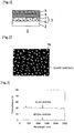
- Fig. 2 illustrates a scanning electronic microscope (SEM) micrograph of an Ag layer 7 made of Ag alone and formed on a quartz substrate, after having been heated for 1 hour at 700°C.
- Fig. 3 illustrates results of light transmittance of the Ag layer 7 before and after heating.
- the Ag in the Ag layer 7 sublimates and aggregates due to heating, and the quartz substrate that is an underlying lower of Ag layer 7 becomes exposed.
- the Ag layer 7 before heating has substantially zero light transmittance at a wavelength region from about 200 nm to 2500 nm (no light is transmitted within this wavelength region), whereas the Ag layer 7 after heating exhibits a light transmittance of about 40% in the wavelength region from about 200 nm to 2500 nm (light is transmitted in this wavelength region).
- the function as the infrared reflective layer 3 (function of reflecting thermal radiation from the heat medium and the tube) is thus not sufficiently brought out by the Ag layer 7 having suffered aggregation and sublimation of Ag, and accordingly the effect in conversion of sunlight to heat is low.
- an Ag layer 7 having Nb 6 dispersed therein is used as the infrared reflective layer 3 in the solar heat collector tube 1 of the present embodiment.
- Nb 6 has the function of suppressing aggregation and sublimation of Ag in the Ag layer 7, as a result of which there is enhanced the heat resistance of the Ag layer 7.
- Fig. 4 illustrates a scanning electronic microscope (SEM) micrograph of an Ag layer 7, formed on a quartz substrate and having had 0.75 at% of Nb 6 dispersed therein, after heating at 700°C for 1 hour.
- Fig. 5 illustrates results of light transmittance of the Ag layer 7 before and after heating the Ag layer at 700°C for 1 hour.
- Fig. 4 illustrates, the quartz substrate underlying the Ag layer 7 does not become exposed, and there is virtually no aggregation or sublimation of Ag, even after heating at 700°C for 1 hour. Moreover the light transmittance of the Ag layer 7 exhibits virtually no change before or after heating, as illustrated in Fig. 5 . Therefore, an Ag layer 7 having Nb 6 dispersed therein allows suppressing aggregation and sublimation of Ag, even when exposed to a high temperature of about 700°C. Accordingly, the function of the Ag layer 7 as an infrared reflective layer 3 (function of reflecting thermal radiation from the heat medium and the tube) is not impaired, and the efficiency of conversion of sunlight to heat does not drop.
- an infrared reflective layer 3 function of reflecting thermal radiation from the heat medium and the tube
- the content of Nb 6 in the Ag layer 7 is 0.1 at% to 31.8 at%, preferably 0.2 at% to 30 at%, more preferably 0.3 at% to 25 at%, yet more preferably 0.4 at% to 20 at% and particularly preferably 0.5 at% to 15 at%, from the viewpoint of suppressing aggregation and sublimation of Ag.
- the thickness of the Ag layer 7 having Nb 6 dispersed therein is not particularly limited, but is preferably 10 nm to 500 nm, more preferably 30 nm to 400 nm, and yet more preferably 50 nm to 300 nm.
- the Ag layer 7 having Nb 6 dispersed therein can be formed through sputtering in the presence of an inert gas such as nitrogen gas, argon gas or the like, using Ag and Nb as a target.
- the sputtering conditions are not particularly limited, and may be adjusted as appropriate depending on the apparatus that is utilized.
- As the target individual targets of Ag and Nb or one target in the form of a mixture of Ag and Nb can be used.
- the sunlight-heat conversion layer 4 formed on the infrared reflective layer 3 has the function of efficiently absorbing sunlight while suppressing heat dissipation by thermal radiation.
- the sunlight-heat conversion layer 4 is also referred to as a light-selective absorption layer.
- a sunlight-heat conversion layer known in the relevant technical field can be used, without particular limitations, as the sunlight-heat conversion layer 4.
- Examples of the sunlight-heat conversion layer 4 include, for instance, a black chromium plating layer, a black nickel plating layer, an electroless nickel blackened layer, a triiron tetraoxide (Iron Oxide black) layer, a cermet layer (layer made up of a composite material of a ceramic and a metal), an iron silicide layer, a manganese silicide layer, a chromium silicide layer, or a layer made up of a composite material of manganese silicide or chromium silicide and a transparent dielectric (for instance, SiO 2 , Al 2 O 3 , AlN or the like).
- the foregoing layers may be single layers or a plurality of layers of two or more types.
- the thickness of the sunlight-heat conversion layer 4 is not particularly limited, but is preferably 1 nm to 10 ⁇ m, and more preferably 5 nm to 100 nm.
- the method for forming the sunlight-heat conversion layer 4 is not particularly limited, and a method known in the relevant technical field can be resorted to.
- the sunlight-heat conversion layer 4 can be formed by chemical vapor deposition, physical vapor deposition (sputtering, vacuum deposition, ion plating or the like), or by plating.
- the anti-reflection layer 5 formed on the sunlight-heat conversion layer 4 has the function to inhibit sunlight reflection.
- anti-reflection layer known in the relevant technical field can be used, without particular limitations, as the anti-reflection layer 5.
- the anti-reflection layer 5 include, for instance, transparent dielectric layers such as such as SiO 2 layers, Al 2 O 3 layers, AlN layers, Cr 2 O 3 layers and the like.
- the thickness of the anti-reflection layer 5 is not particularly limited, but is preferably 10 nm to 500 nm.
- the method for forming the anti-reflection layer 5 is not particularly limited, and a method known in the relevant technical field can be resorted to.
- the anti-reflection layer 5 can be formed by chemical vapor deposition or physical vapor deposition (sputtering, vacuum deposition or ion plating).
- the solar heat collector tube 1 of the present embodiment having such features is thereby provided with an infrared reflective layer 3 that suppresses aggregation and sublimation of Ag, and accordingly drops in the efficiency of conversion of sunlight to heat become less likely.
- Fig. 6 is a partial cross-sectional diagram of a solar heat collector tube of the present embodiment.
- a solar heat collector tube 10 of the present embodiment differs from the solar heat collector tube 1 of Embodiment 1 in that a metal protective layer 11 is provided between the infrared reflective layer 3 and the sunlight-heat conversion layer 4.
- a metal protective layer 11 is provided between the infrared reflective layer 3 and the sunlight-heat conversion layer 4.
- Other features are identical to those of the solar heat collector tube 1 of Embodiment 1, and accordingly will not be explained.
- the metal protective layer 11 has the function of making Ag contained in the infrared reflective layer 3 less likely to sublimate. Accordingly, sublimation of Ag contained in the infrared reflective layer 3 can be further suppressed, and impairment of the function of the infrared reflective layer 3 made less likely, by formation of the metal protective layer 11 between the infrared reflective layer 3 and the sunlight-heat conversion layer 4.
- the metal protective layer used in the metal protective layer 11 is not particularly limited so long as the layer has the function of making Ag less likely to sublimate, and generally the layer is a metal protective layer formed out of a material of a higher melting point than that of Ag (melting point 961.8°C).
- materials having a melting point higher than that of Ag include, for instance, Nb (melting point 2469°C), Mo (melting point 2623°C), W (melting point 3422°C), Cu (melting point 1085°C), Ni (melting point 1455°C), Fe (melting point 1538°C), Cr (melting point 1907°C), Ta (melting point 3020°C) and the like.
- the material that forms the metal protective layer 11 has high reflectance towards light in the infrared region.
- Nb has a reflectance of 96.1%, Mo of 97.1%, W of 95.2%, Cu of 97.4%, Ni of 86.4%, Fe of 81.8%, Cr of 81.3%, and Ta of 97.3%, towards infrared light at a wavelength of 2500 nm; preferred herein are thus Ta, Nb, Mo, W and Cu having a reflectance towards light in the infrared region in excess of 90%.
- the thickness of the metal protective layer 11 may be set as appropriate for instance depending on the type of material that is used and is not particularly limited, but is preferably smaller than the thickness of the infrared reflective layer 3, from the viewpoint of suppressing thermal radiation.
- An appropriate thickness of the metal protective layer 11 formed on the infrared reflective layer 3 may be worked out by calculating emissivity on the basis of the results of a multilayer film approximation using the optical constants of the materials that are utilized in the infrared reflective layer 3 and the metal protective layer 11.
- emissivity at 650°C can be made lower than that of a Cu layer by prescribing the thickness of the metal protective layer 11 (Mo layer) to lie in the range of 0.1 nm to 40.5 nm.
- emissivity at 650°C can be made lower than that of a Cu layer by prescribing the thickness of the metal protective layer 11 (W layer) to lie in the range of 0.1 nm to 14.5 nm.
- emissivity at 650°C can be made lower than that of a Cu layer by prescribing the thickness of the metal protective layer 11 (Nb layer) to lie in the range of 0.1 nm to 5.9 nm.
- the method for forming the metal protective layer 11 is not particularly limited, and a method known in the relevant technical field can be resorted to.
- the metal protective layer 11 can be formed by chemical vapor deposition or physical vapor deposition (sputtering, vacuum deposition or ion plating).
- a solar heat collector tube 10 of the present embodiment having such features allows yet further suppression of sublimation of Ag contained in the infrared reflective layer 3, and accordingly impairment of the function of the infrared reflective layer 3 becomes yet less likely. Therefore, drops in efficiency of conversion of sunlight to heat are yet less likely in the solar heat collector tube 10.
- Fig. 7 is a partial cross-sectional diagram of a solar heat collector tube of the present embodiment.
- a solar heat collector tube 20 of the present embodiment differs from the solar heat collector tube 10 of Embodiment 2 in that a metal protective layer 11 is further provided between the tube 2 and the infrared reflective layer 3.
- Other features are identical to those of the solar heat collector tube 10 of Embodiment 2, and accordingly will not be explained.
- the features of the present embodiment can apply also to the solar heat collector tube 1 of Embodiment 1.
- the metal protective layer 11 provided between the tube 2 and the infrared reflective layer 3 is provided as the underlying base of the infrared reflective layer 3, and has the function of facilitating uniform formation of the infrared reflective layer 3. Accordingly, the infrared reflective layer 3 can be formed uniformly, and the function of the infrared reflective layer 3 can be obtained stably, by formation of the metal protective layer 11 between the tube 2 and the infrared reflective layer 3.
- the metal protective layer 11 that is provided between the tube 2 and the infrared reflective layer 3 is not particularly limited, and there can be used the same metal protective layer 11 that is provided on the infrared reflective layer 3.
- the thickness of the metal protective layer 11 provided between the tube 2 and the infrared reflective layer 3 is not particularly limited, so long as the function of the metal protective layer 11 as an underlying base can be brought out, but is generally 1 nm to 100 nm, preferably 3 nm to 50 nm, and more preferably 5 nm to 30 nm.
- the solar heat collector tube 20 of the present embodiment having such features allows the function of the infrared reflective layer 3 to stably achieved.
- Fig. 8 is a partial cross-sectional diagram of a solar heat collector tube of the present embodiment.
- a solar heat collector tube 30 of the present embodiment differs from the solar heat collector tube 20 of Embodiment 3 in that an oxygen barrier layer 12 is provided between the metal protective layer 11 and the sunlight-heat conversion layer 4.
- Other features are identical to those of the solar heat collector tube 20 of Embodiment 3, and accordingly will not be explained.
- the features of the present embodiment can apply also to the solar heat collector tube 10 of Embodiment 2.
- the oxygen barrier layer 12 is provided for the purpose of preventing passage of oxygen, which gives rise to oxidation of the metal protective layer 11. Accordingly, oxidation of the metal protective layer 11 can be prevented by formation of the oxygen barrier layer 12 between the metal protective layer 11 and the sunlight-heat conversion layer 4, and accordingly impairment of the function of the metal protective layer 11 becomes less likely.
- the oxygen barrier layer 12 is not particularly limited and any oxygen barrier layer can be employed so long as the passage of oxygen thereof is not easy, and, for instance, a dielectric layer can be used as the oxygen barrier layer 12.
- dielectric layers include, for instance, SiO 2 layers, Al 2 O 3 layers, AlN layers, Cr 2 O 3 layers and Si 3 N 4 layers.
- the thickness of the oxygen barrier layer 12 is not particularly limited, so long as passage of oxygen is precluded, but is generally 1 nm to 100 nm, preferably 3 nm to 50 nm, and more preferably 5 nm to 30 nm.
- the method for forming the oxygen barrier layer 12 is not particularly limited, and a method known in the relevant technical field can be resorted to.
- the oxygen barrier layer 12 can be formed by chemical vapor deposition or physical vapor deposition (sputtering, vacuum deposition or ion plating).
- Fig. 10 illustrates the results of light transmittance of the stack before and after heating of the stack at 700°C for 1 hour, 11 hours and 51 hours. As Fig. 10 reveals, the light transmittance of the stack exhibits virtually no change before or after heating. By adopting such a multilayer structure, therefore, the functions of the various layers are not impaired and the efficiency of conversion of sunlight to heat does not drop.
- the solar heat collector tube 30 of the present embodiment having such features allows prevention of impairment in the function of the metal protective layer 11 caused by oxidation thereof.
- Fig. 11 is a partial cross-sectional diagram of a solar heat collector tube of the present embodiment.
- a solar heat collector tube 40 of the present embodiment differs from the solar heat collector tube 30 of Embodiment 4 in that herein a diffusion preventing layer 13 is provided between the tube 2 and the infrared reflective layer 3.
- Other features are identical to those of the solar heat collector tube 30 of Embodiment 4, and accordingly will not be explained.
- the features of the present embodiment can also apply to the solar heat collector tube 1 of Embodiment 1, the solar heat collector tube 10 of Embodiment 2 and the solar heat collector tube 20 of Embodiment 3.
- the diffusion preventing layer 13 is provided for the purpose of preventing components of the tube 2 (for instance, Cr) from diffusing into the layer (metal protective layer 11 in Fig. 11 ) overlying the tube 2. Impairment of the function of the layer (metal protective layer 11 in Fig. 11 ) overlying the tube 2 becomes less likely by formation of the diffusion preventing layer 13 on the outer surface of the tube 2.
- a diffusion preventing layer known in the relevant technical field can be used, without particular limitations, as the diffusion preventing layer 13.
- Examples of materials used in the diffusion preventing layer 13 include, for instance, oxides such as SiO 2 and Al 2 O 3 , and nitrides such as Si 3 N 4 and AlN.
- the thickness of the diffusion preventing layer 13 is not particularly limited, so long as components in the tube 2 can be prevented from diffusing into the layer above, but is generally of 1 nm to 100 nm, preferably 3 nm to 50 nm, and more preferably 5 nm to 30 nm.
- the method for forming the diffusion preventing layer 13 is not particularly limited, and a method known in the relevant technical field can be resorted to.
- the diffusion preventing layer 13 can be formed by chemical vapor deposition or physical vapor deposition (sputtering, vacuum deposition or ion plating).
- the solar heat collector tube 40 of the present embodiment having such features allows prevention of impairment in the function of the layer overlying the tube 2.
- Fig. 12 is a partial cross-sectional diagram of a solar heat collector tube of the present embodiment.
- a solar heat collector tube 50 of the present embodiment differs from the solar heat collector tube 40 of Embodiment 5 in that a reaction preventing layer 14 is provided between the metal protective layer 11 and the oxygen barrier layer 12.
- Other features are identical to those of the solar heat collector tube 40 of Embodiment 5, and accordingly will not be explained.
- the features of the present embodiment can also apply to the solar heat collector tube 30 of Embodiment 4.
- the reaction preventing layer 14 is provided in order to prevent reactions between the metal protective layer 11 and the oxygen barrier layer 12. Impairment of the functions of the metal protective layer 11 and of the oxygen barrier layer 12 becomes accordingly less likely by providing the reaction preventing layer 14 between the metal protective layer 11 and the oxygen barrier layer 12.
- the reaction preventing layer 14 allows preventing reactions between the metal protective layer 11 and the sunlight-heat conversion layer 4.
- the reaction prevention of layer 14 also has the function of preventing passage of oxygen, and accordingly can substitute for the oxygen barrier layer 12 in this case.
- the reaction preventing layer 14 is not particularly limited, so long as reactions between the metal protective layer 11 and the oxygen barrier layer 12 or the sunlight-heat conversion layer 4 are less likely, and a layer known in the relevant technical field can be used as the reaction preventing layer 14.
- Examples of materials utilized in the reaction preventing layer 14 include, for instance, silicides such as niobium silicide (NbSi 2 ) and tantalum silicide (TaSi 2 ).
- the material of the reaction preventing layer 14 is preferably a silicide of a metal that is used in the metal protective layer 11.
- the thickness of the reaction preventing layer 14 is not particularly limited so long as reactions between the metal protective layer 11 and the oxygen barrier layer 12 or the sunlight-heat conversion layer 4 can be prevented, but is generally 1 nm to 200 nm, preferably 3 nm to 100 nm and more preferably 5 nm to 80 nm.
- the method for forming the reaction preventing layer 14 is not particularly limited, and a method known in the relevant technical field can be resorted to.
- the reaction preventing layer 14 can be formed by chemical vapor deposition, physical vapor deposition (sputtering, vacuum deposition or ion plating).
- the solar heat collector tube 50 of the present embodiment having such features allows prevention of impairment of the function of the metal protective layer 11 and the oxygen barrier layer 12 or the sunlight-heat conversion layer 4.
- Fig. 13 is a partial cross-sectional diagram of a solar heat collector tube of the present embodiment.
- a solar heat collector tube 60 of the present embodiment differs from the solar heat collector tube 50 of Embodiment 6 in that a reaction preventing layer 14 is provided between the diffusion preventing layer 13 and the metal protective layer 11.
- Other features are identical to those of the solar heat collector tube 50 of Embodiment 6, and accordingly will not be explained.
- the features of the present embodiment can apply also to the solar heat collector tube 40 of Embodiment 5.
- the reaction preventing layer 14 that is provided between the diffusion preventing layer 13 and the metal protective layer 11 is provided in order to prevent reactions between the diffusion preventing layer 13 and the metal protective layer 11. Accordingly, impairment of the functions of the diffusion preventing layer 13 and the metal protective layer 11 becomes less likely by providing the reaction preventing layer 14 between the diffusion preventing layer 13 and the metal protective layer 11.
- reaction preventing layer identical to the reaction preventing layer 14 that is provided between the metal protective layer 11 and the oxygen barrier layer 12 can be used as the reaction preventing layer 14 that is provided between the diffusion preventing layer 13 and the metal protective layer 11.
- the material of the reaction preventing layer 14 is preferably a silicide of a metal that is used in the metal protective layer 11.
- the thickness of the reaction preventing layer 14 that is provided between the diffusion preventing layer 13 and the metal protective layer 11 is not particularly limited, so long as reactions between the diffusion preventing layer 13 and the metal protective layer 11 can be prevented, but is generally 1 nm to 150 nm, preferably 5 nm to 100 nm and more preferably 10 nm to 80 nm.
- Fig. 14 illustrates the results of light transmittance of the stack before and after heating of the stack at 700°C for 1 hour, 11 hours and 51 hours. As Fig. 15 reveals, the light transmittance of the stack exhibits virtually no change before or after heating. By adopting such a multilayer structure, therefore, the functions of the various layers are not impaired and the efficiency of conversion of sunlight to heat does not drop.
- the solar heat collector tube 60 of the present embodiment having such features allows prevention of impairment of the functions of the metal protective layer 11 and the diffusion preventing layer 13.
Landscapes
- Engineering & Computer Science (AREA)
- Physics & Mathematics (AREA)
- Life Sciences & Earth Sciences (AREA)
- Sustainable Development (AREA)
- Sustainable Energy (AREA)
- Thermal Sciences (AREA)
- Chemical & Material Sciences (AREA)
- Combustion & Propulsion (AREA)
- Mechanical Engineering (AREA)
- General Engineering & Computer Science (AREA)
- Ceramic Engineering (AREA)
- Laminated Bodies (AREA)
Claims (7)
- Tube de collecteur de chaleur solaire (1, 10, 20, 30, 40, 50, 60) dans lequel au moins une couche réfléchissant les infrarouges (3), une couche de conversion de lumière solaire en chaleur (4) et une couche antireflet (5) sont disposées sur la surface extérieure d'un tube (2), à travers l'intérieur duquel un milieu caloporteur peut circuler,
dans lequel la couche réfléchissant les infrarouges est une couche d'Ag (7), caractérisé en ce que la couche d'Ag (7) a du Nb (6) dispersé dans celle-ci, et la teneur en Nb (6) est de 0,1 % atomique à 31,8 % atomiques, et
dans lequel une couche protectrice métallique (11) qui supprime la sublimation de l'Ag contenu dans la couche réfléchissant les infrarouges (3) est disposée entre la couche réfléchissant les infrarouges (3) et la couche de conversion de lumière solaire en chaleur (4). - Tube de collecteur de chaleur solaire (10, 20, 30, 40, 50, 60) selon la revendication 1, dans lequel la couche protectrice métallique (11) est formée d'un matériau choisi parmi Nb, Mo, W, Cu, Ni, Fe, Cr et Ta.
- Tube de collecteur de chaleur solaire (20, 30, 40, 50, 60) selon la revendication 1 ou 2, dans lequel une couche protectrice métallique (11) est disposée entre le tube (2) et la couche réfléchissant les infrarouges (3).
- Tube de collecteur de chaleur solaire (30, 40, 50, 60) selon l'une quelconque des revendications 1 à 3, dans lequel une couche formant barrière à l'oxygène (12) est disposée entre la couche protectrice métallique (11) et la couche de conversion de lumière solaire en chaleur (4).
- Tube de collecteur de chaleur solaire (40, 50, 60) selon l'une quelconque des revendications 1 à 3, dans lequel une couche empêchant la diffusion (13) est en outre disposée entre le tube (2) et la couche réfléchissant les infrarouges (3) .
- Tube de collecteur de chaleur solaire (50, 60) selon l'une quelconque des revendications 1 à 5, dans lequel une couche empêchant une réaction (14) est disposée entre la couche protectrice métallique (11) et la couche formant barrière à l'oxygène (12) ou la couche de conversion de lumière solaire en chaleur (4).
- Tube de collecteur de chaleur solaire (60) selon la revendication 5 ou 6, dans lequel une couche empêchant une réaction (14) est disposée entre la couche empêchant la diffusion (13) et la couche protectrice métallique (11).
Applications Claiming Priority (2)
| Application Number | Priority Date | Filing Date | Title |
|---|---|---|---|
| JP2016015492A JP6549491B2 (ja) | 2016-01-29 | 2016-01-29 | 太陽熱集熱管 |
| PCT/JP2016/084341 WO2017130535A1 (fr) | 2016-01-29 | 2016-11-18 | Tube de collecte de chaleur solaire |
Publications (3)
| Publication Number | Publication Date |
|---|---|
| EP3410031A1 EP3410031A1 (fr) | 2018-12-05 |
| EP3410031A4 EP3410031A4 (fr) | 2019-07-03 |
| EP3410031B1 true EP3410031B1 (fr) | 2020-12-23 |
Family
ID=59397870
Family Applications (1)
| Application Number | Title | Priority Date | Filing Date |
|---|---|---|---|
| EP16888120.9A Not-in-force EP3410031B1 (fr) | 2016-01-29 | 2016-11-18 | Tube de collecte de chaleur solaire |
Country Status (6)
| Country | Link |
|---|---|
| US (1) | US11231208B2 (fr) |
| EP (1) | EP3410031B1 (fr) |
| JP (1) | JP6549491B2 (fr) |
| CN (1) | CN108603692B (fr) |
| ES (1) | ES2856757T3 (fr) |
| WO (1) | WO2017130535A1 (fr) |
Family Cites Families (24)
| Publication number | Priority date | Publication date | Assignee | Title |
|---|---|---|---|---|
| IN185567B (fr) * | 1991-07-19 | 2001-03-03 | Univ Sydney | |
| JP3404165B2 (ja) * | 1994-03-30 | 2003-05-06 | 日本板硝子株式会社 | 熱線遮蔽ガラス |
| US7514037B2 (en) * | 2002-08-08 | 2009-04-07 | Kobe Steel, Ltd. | AG base alloy thin film and sputtering target for forming AG base alloy thin film |
| US20050238923A1 (en) * | 2004-04-27 | 2005-10-27 | Thiel James P | Hybrid coating stack |
| US7838134B2 (en) * | 2004-11-23 | 2010-11-23 | Lawrence Livermore National Security, Llc | Durable silver mirror with ultra-violet thru far infra-red reflection |
| FR2893024B1 (fr) * | 2005-11-08 | 2008-02-29 | Saint Gobain | Substrat muni d'un empilement a proprietes thermiques |
| DE102006056536B9 (de) * | 2006-11-27 | 2008-06-05 | Schott Ag | Strahlungsselektive Absorberbeschichtung, Absorberrohr und Verfahren zu dessen Herstellung |
| JP2009093750A (ja) * | 2007-10-09 | 2009-04-30 | Hitachi Maxell Ltd | 光情報記録媒体 |
| US8893711B2 (en) * | 2007-10-18 | 2014-11-25 | Alliance For Sustainable Energy, Llc | High temperature solar selective coatings |
| DE102008010199A1 (de) * | 2008-02-20 | 2009-08-27 | Schott Ag | Strahlungsselektive Absorberbeschichtung, Absorberrohr und Verfahren zu dessen Herstellung |
| ES2316321B2 (es) | 2008-10-20 | 2010-12-14 | Abengoa Solar New Technologies, S.A. | Recubrimiento absorbente selectivo solar y metodo de fabricacion. |
| DE102009022059A1 (de) | 2009-05-20 | 2010-11-25 | Schott Solar Ag | Strahlungsselektive Absorberbeschichtung und Absorberrohr mit strahlungsselektiver Absorberbeschichtung |
| WO2011005319A1 (fr) * | 2009-07-09 | 2011-01-13 | Xunlight Corporation | Rétroréflecteur pour dispositifs photovoltaïques |
| CN102102918B (zh) * | 2011-02-16 | 2012-09-05 | 北京天瑞星光热技术有限公司 | 一种Cr系高温太阳能选择性吸收涂层及其制备方法 |
| WO2012123038A1 (fr) | 2011-03-17 | 2012-09-20 | Von Ardenne Anlagentechnik Gmbh | Système de couches de réflexion pour des applications solaires et procédé de fabrication |
| WO2012172148A1 (fr) * | 2011-06-16 | 2012-12-20 | Consejo Superior De Investigaciones Científicas (Csic) | Revêtement à absorption sélective du rayonnement visible et infrarouge et son procédé d'obtention |
| JP5687606B2 (ja) * | 2011-11-14 | 2015-03-18 | トヨタ自動車株式会社 | 太陽光−熱変換部材、太陽光−熱変換装置、及び太陽熱発電装置 |
| JP2015166637A (ja) * | 2012-07-03 | 2015-09-24 | 旭硝子株式会社 | 光選択吸収膜、集熱管および太陽熱発電装置 |
| CN103105011B (zh) | 2013-01-31 | 2015-05-13 | 中国科学院上海技术物理研究所 | 适于中高温热利用的太阳能选择性吸收膜系及其制备方法 |
| US20140261390A1 (en) * | 2013-03-13 | 2014-09-18 | Brightsource Industries (Israel) Ltd. | High temperature radiation-selective coating and related apparatus |
| JP2015227767A (ja) * | 2014-05-08 | 2015-12-17 | 株式会社豊田自動織機 | 太陽熱集熱装置及びその製造方法 |
| CN104005003B (zh) * | 2014-05-28 | 2017-03-22 | 北京天瑞星光热技术有限公司 | 一种大气中耐高温、耐盐雾的太阳能选择性吸收涂层及其制备方法 |
| FR3023362A1 (fr) * | 2014-07-04 | 2016-01-08 | Commissariat Energie Atomique | Absorbeur solaire selectif a couche epaisse de passivation anticorrosion et barriere thermique pour des applications hautes temperatures et son procede de realisation. |
| CN104230182A (zh) * | 2014-09-28 | 2014-12-24 | 中国建材国际工程集团有限公司 | 高透过率可钢化低辐射镀膜玻璃的制备方法 |
-
2016
- 2016-01-29 JP JP2016015492A patent/JP6549491B2/ja not_active Expired - Fee Related
- 2016-11-18 EP EP16888120.9A patent/EP3410031B1/fr not_active Not-in-force
- 2016-11-18 WO PCT/JP2016/084341 patent/WO2017130535A1/fr not_active Ceased
- 2016-11-18 ES ES16888120T patent/ES2856757T3/es active Active
- 2016-11-18 CN CN201680080224.5A patent/CN108603692B/zh not_active Expired - Fee Related
- 2016-11-18 US US16/073,398 patent/US11231208B2/en not_active Expired - Fee Related
Also Published As
| Publication number | Publication date |
|---|---|
| US11231208B2 (en) | 2022-01-25 |
| US20190041098A1 (en) | 2019-02-07 |
| EP3410031A4 (fr) | 2019-07-03 |
| ES2856757T3 (es) | 2021-09-28 |
| JP2017133786A (ja) | 2017-08-03 |
| WO2017130535A1 (fr) | 2017-08-03 |
| CN108603692B (zh) | 2020-12-18 |
| CN108603692A (zh) | 2018-09-28 |
| JP6549491B2 (ja) | 2019-07-24 |
| EP3410031A1 (fr) | 2018-12-05 |
Similar Documents
| Publication | Publication Date | Title |
|---|---|---|
| US9546801B2 (en) | Solar-thermal conversion member, solar-thermal conversion device, and solar thermal power generation device comprising a β-FeSi2 phase material | |
| EP3410030B1 (fr) | Tube de collecte de chaleur solaire et son procédé de production | |
| El-Mahallawy et al. | Design and simulation of different multilayer solar selective coatings for solar thermal applications | |
| EP3410032B1 (fr) | Tube de collecte de chaleur solaire | |
| CN102615878A (zh) | 一种中高温太阳能选择性吸收涂层及其制备方法 | |
| US11231208B2 (en) | Solar heat collector tube | |
| Spitz | Selective surfaces for high temperature solar photothermal conversion | |
| JP6995025B2 (ja) | 太陽熱集熱管 | |
| EP3255357B1 (fr) | Tube de captation de chaleur solaire, dispositif de conversion lumière solaire/chaleur et dispositif de production d'énergie solaire | |
| Mengali | First surface flexible optical solar reflectors with interferential cermet coatings |
Legal Events
| Date | Code | Title | Description |
|---|---|---|---|
| STAA | Information on the status of an ep patent application or granted ep patent |
Free format text: STATUS: THE INTERNATIONAL PUBLICATION HAS BEEN MADE |
|
| PUAI | Public reference made under article 153(3) epc to a published international application that has entered the european phase |
Free format text: ORIGINAL CODE: 0009012 |
|
| STAA | Information on the status of an ep patent application or granted ep patent |
Free format text: STATUS: REQUEST FOR EXAMINATION WAS MADE |
|
| 17P | Request for examination filed |
Effective date: 20180802 |
|
| AK | Designated contracting states |
Kind code of ref document: A1 Designated state(s): AL AT BE BG CH CY CZ DE DK EE ES FI FR GB GR HR HU IE IS IT LI LT LU LV MC MK MT NL NO PL PT RO RS SE SI SK SM TR |
|
| AX | Request for extension of the european patent |
Extension state: BA ME |
|
| RIC1 | Information provided on ipc code assigned before grant |
Ipc: F24J 2/48 20060101AFI20170818BHEP Ipc: F24J 2/24 20060101ALI20170818BHEP |
|
| DAV | Request for validation of the european patent (deleted) | ||
| DAX | Request for extension of the european patent (deleted) | ||
| A4 | Supplementary search report drawn up and despatched |
Effective date: 20190605 |
|
| RIC1 | Information provided on ipc code assigned before grant |
Ipc: F24S 10/70 20180101ALI20190529BHEP Ipc: F24S 70/30 20180101AFI20190529BHEP |
|
| REG | Reference to a national code |
Ref country code: DE Ref legal event code: R079 Ref document number: 602016050415 Country of ref document: DE Free format text: PREVIOUS MAIN CLASS: F24J0002480000 Ipc: F24S0070300000 |
|
| GRAP | Despatch of communication of intention to grant a patent |
Free format text: ORIGINAL CODE: EPIDOSNIGR1 |
|
| STAA | Information on the status of an ep patent application or granted ep patent |
Free format text: STATUS: GRANT OF PATENT IS INTENDED |
|
| RIC1 | Information provided on ipc code assigned before grant |
Ipc: F24S 70/30 20180101AFI20200701BHEP Ipc: F24S 10/70 20180101ALI20200701BHEP Ipc: F24S 70/10 20180101ALI20200701BHEP |
|
| INTG | Intention to grant announced |
Effective date: 20200724 |
|
| GRAS | Grant fee paid |
Free format text: ORIGINAL CODE: EPIDOSNIGR3 |
|
| GRAA | (expected) grant |
Free format text: ORIGINAL CODE: 0009210 |
|
| STAA | Information on the status of an ep patent application or granted ep patent |
Free format text: STATUS: THE PATENT HAS BEEN GRANTED |
|
| AK | Designated contracting states |
Kind code of ref document: B1 Designated state(s): AL AT BE BG CH CY CZ DE DK EE ES FI FR GB GR HR HU IE IS IT LI LT LU LV MC MK MT NL NO PL PT RO RS SE SI SK SM TR |
|
| REG | Reference to a national code |
Ref country code: GB Ref legal event code: FG4D |
|
| REG | Reference to a national code |
Ref country code: DE Ref legal event code: R096 Ref document number: 602016050415 Country of ref document: DE |
|
| REG | Reference to a national code |
Ref country code: AT Ref legal event code: REF Ref document number: 1348124 Country of ref document: AT Kind code of ref document: T Effective date: 20210115 |
|
| REG | Reference to a national code |
Ref country code: IE Ref legal event code: FG4D |
|
| PG25 | Lapsed in a contracting state [announced via postgrant information from national office to epo] |
Ref country code: GR Free format text: LAPSE BECAUSE OF FAILURE TO SUBMIT A TRANSLATION OF THE DESCRIPTION OR TO PAY THE FEE WITHIN THE PRESCRIBED TIME-LIMIT Effective date: 20210324 Ref country code: FI Free format text: LAPSE BECAUSE OF FAILURE TO SUBMIT A TRANSLATION OF THE DESCRIPTION OR TO PAY THE FEE WITHIN THE PRESCRIBED TIME-LIMIT Effective date: 20201223 Ref country code: RS Free format text: LAPSE BECAUSE OF FAILURE TO SUBMIT A TRANSLATION OF THE DESCRIPTION OR TO PAY THE FEE WITHIN THE PRESCRIBED TIME-LIMIT Effective date: 20201223 Ref country code: NO Free format text: LAPSE BECAUSE OF FAILURE TO SUBMIT A TRANSLATION OF THE DESCRIPTION OR TO PAY THE FEE WITHIN THE PRESCRIBED TIME-LIMIT Effective date: 20210323 |
|
| REG | Reference to a national code |
Ref country code: AT Ref legal event code: MK05 Ref document number: 1348124 Country of ref document: AT Kind code of ref document: T Effective date: 20201223 |
|
| REG | Reference to a national code |
Ref country code: NL Ref legal event code: MP Effective date: 20201223 |
|
| PG25 | Lapsed in a contracting state [announced via postgrant information from national office to epo] |
Ref country code: SE Free format text: LAPSE BECAUSE OF FAILURE TO SUBMIT A TRANSLATION OF THE DESCRIPTION OR TO PAY THE FEE WITHIN THE PRESCRIBED TIME-LIMIT Effective date: 20201223 Ref country code: BG Free format text: LAPSE BECAUSE OF FAILURE TO SUBMIT A TRANSLATION OF THE DESCRIPTION OR TO PAY THE FEE WITHIN THE PRESCRIBED TIME-LIMIT Effective date: 20210323 Ref country code: LV Free format text: LAPSE BECAUSE OF FAILURE TO SUBMIT A TRANSLATION OF THE DESCRIPTION OR TO PAY THE FEE WITHIN THE PRESCRIBED TIME-LIMIT Effective date: 20201223 |
|
| PG25 | Lapsed in a contracting state [announced via postgrant information from national office to epo] |
Ref country code: NL Free format text: LAPSE BECAUSE OF FAILURE TO SUBMIT A TRANSLATION OF THE DESCRIPTION OR TO PAY THE FEE WITHIN THE PRESCRIBED TIME-LIMIT Effective date: 20201223 Ref country code: HR Free format text: LAPSE BECAUSE OF FAILURE TO SUBMIT A TRANSLATION OF THE DESCRIPTION OR TO PAY THE FEE WITHIN THE PRESCRIBED TIME-LIMIT Effective date: 20201223 |
|
| REG | Reference to a national code |
Ref country code: LT Ref legal event code: MG9D |
|
| PG25 | Lapsed in a contracting state [announced via postgrant information from national office to epo] |
Ref country code: PT Free format text: LAPSE BECAUSE OF FAILURE TO SUBMIT A TRANSLATION OF THE DESCRIPTION OR TO PAY THE FEE WITHIN THE PRESCRIBED TIME-LIMIT Effective date: 20210423 Ref country code: RO Free format text: LAPSE BECAUSE OF FAILURE TO SUBMIT A TRANSLATION OF THE DESCRIPTION OR TO PAY THE FEE WITHIN THE PRESCRIBED TIME-LIMIT Effective date: 20201223 Ref country code: SK Free format text: LAPSE BECAUSE OF FAILURE TO SUBMIT A TRANSLATION OF THE DESCRIPTION OR TO PAY THE FEE WITHIN THE PRESCRIBED TIME-LIMIT Effective date: 20201223 Ref country code: SM Free format text: LAPSE BECAUSE OF FAILURE TO SUBMIT A TRANSLATION OF THE DESCRIPTION OR TO PAY THE FEE WITHIN THE PRESCRIBED TIME-LIMIT Effective date: 20201223 Ref country code: LT Free format text: LAPSE BECAUSE OF FAILURE TO SUBMIT A TRANSLATION OF THE DESCRIPTION OR TO PAY THE FEE WITHIN THE PRESCRIBED TIME-LIMIT Effective date: 20201223 Ref country code: CZ Free format text: LAPSE BECAUSE OF FAILURE TO SUBMIT A TRANSLATION OF THE DESCRIPTION OR TO PAY THE FEE WITHIN THE PRESCRIBED TIME-LIMIT Effective date: 20201223 Ref country code: EE Free format text: LAPSE BECAUSE OF FAILURE TO SUBMIT A TRANSLATION OF THE DESCRIPTION OR TO PAY THE FEE WITHIN THE PRESCRIBED TIME-LIMIT Effective date: 20201223 |
|
| PG25 | Lapsed in a contracting state [announced via postgrant information from national office to epo] |
Ref country code: AT Free format text: LAPSE BECAUSE OF FAILURE TO SUBMIT A TRANSLATION OF THE DESCRIPTION OR TO PAY THE FEE WITHIN THE PRESCRIBED TIME-LIMIT Effective date: 20201223 Ref country code: PL Free format text: LAPSE BECAUSE OF FAILURE TO SUBMIT A TRANSLATION OF THE DESCRIPTION OR TO PAY THE FEE WITHIN THE PRESCRIBED TIME-LIMIT Effective date: 20201223 |
|
| REG | Reference to a national code |
Ref country code: DE Ref legal event code: R097 Ref document number: 602016050415 Country of ref document: DE |
|
| REG | Reference to a national code |
Ref country code: ES Ref legal event code: FG2A Ref document number: 2856757 Country of ref document: ES Kind code of ref document: T3 Effective date: 20210928 |
|
| PG25 | Lapsed in a contracting state [announced via postgrant information from national office to epo] |
Ref country code: IS Free format text: LAPSE BECAUSE OF FAILURE TO SUBMIT A TRANSLATION OF THE DESCRIPTION OR TO PAY THE FEE WITHIN THE PRESCRIBED TIME-LIMIT Effective date: 20210423 |
|
| PG25 | Lapsed in a contracting state [announced via postgrant information from national office to epo] |
Ref country code: AL Free format text: LAPSE BECAUSE OF FAILURE TO SUBMIT A TRANSLATION OF THE DESCRIPTION OR TO PAY THE FEE WITHIN THE PRESCRIBED TIME-LIMIT Effective date: 20201223 |
|
| PLBE | No opposition filed within time limit |
Free format text: ORIGINAL CODE: 0009261 |
|
| STAA | Information on the status of an ep patent application or granted ep patent |
Free format text: STATUS: NO OPPOSITION FILED WITHIN TIME LIMIT |
|
| PG25 | Lapsed in a contracting state [announced via postgrant information from national office to epo] |
Ref country code: DK Free format text: LAPSE BECAUSE OF FAILURE TO SUBMIT A TRANSLATION OF THE DESCRIPTION OR TO PAY THE FEE WITHIN THE PRESCRIBED TIME-LIMIT Effective date: 20201223 |
|
| 26N | No opposition filed |
Effective date: 20210924 |
|
| PGFP | Annual fee paid to national office [announced via postgrant information from national office to epo] |
Ref country code: DE Payment date: 20210929 Year of fee payment: 6 Ref country code: ES Payment date: 20211202 Year of fee payment: 6 |
|
| PG25 | Lapsed in a contracting state [announced via postgrant information from national office to epo] |
Ref country code: SI Free format text: LAPSE BECAUSE OF FAILURE TO SUBMIT A TRANSLATION OF THE DESCRIPTION OR TO PAY THE FEE WITHIN THE PRESCRIBED TIME-LIMIT Effective date: 20201223 |
|
| PGFP | Annual fee paid to national office [announced via postgrant information from national office to epo] |
Ref country code: IT Payment date: 20211012 Year of fee payment: 6 |
|
| PG25 | Lapsed in a contracting state [announced via postgrant information from national office to epo] |
Ref country code: IS Free format text: LAPSE BECAUSE OF FAILURE TO SUBMIT A TRANSLATION OF THE DESCRIPTION OR TO PAY THE FEE WITHIN THE PRESCRIBED TIME-LIMIT Effective date: 20210423 |
|
| PG25 | Lapsed in a contracting state [announced via postgrant information from national office to epo] |
Ref country code: MC Free format text: LAPSE BECAUSE OF FAILURE TO SUBMIT A TRANSLATION OF THE DESCRIPTION OR TO PAY THE FEE WITHIN THE PRESCRIBED TIME-LIMIT Effective date: 20201223 |
|
| REG | Reference to a national code |
Ref country code: CH Ref legal event code: PL |
|
| GBPC | Gb: european patent ceased through non-payment of renewal fee |
Effective date: 20211118 |
|
| PG25 | Lapsed in a contracting state [announced via postgrant information from national office to epo] |
Ref country code: LU Free format text: LAPSE BECAUSE OF NON-PAYMENT OF DUE FEES Effective date: 20211118 Ref country code: BE Free format text: LAPSE BECAUSE OF NON-PAYMENT OF DUE FEES Effective date: 20211130 |
|
| REG | Reference to a national code |
Ref country code: BE Ref legal event code: MM Effective date: 20211130 |
|
| PG25 | Lapsed in a contracting state [announced via postgrant information from national office to epo] |
Ref country code: LI Free format text: LAPSE BECAUSE OF NON-PAYMENT OF DUE FEES Effective date: 20211130 Ref country code: CH Free format text: LAPSE BECAUSE OF NON-PAYMENT OF DUE FEES Effective date: 20211130 |
|
| PG25 | Lapsed in a contracting state [announced via postgrant information from national office to epo] |
Ref country code: IE Free format text: LAPSE BECAUSE OF NON-PAYMENT OF DUE FEES Effective date: 20211118 Ref country code: GB Free format text: LAPSE BECAUSE OF NON-PAYMENT OF DUE FEES Effective date: 20211118 |
|
| PG25 | Lapsed in a contracting state [announced via postgrant information from national office to epo] |
Ref country code: FR Free format text: LAPSE BECAUSE OF NON-PAYMENT OF DUE FEES Effective date: 20211130 |
|
| REG | Reference to a national code |
Ref country code: DE Ref legal event code: R119 Ref document number: 602016050415 Country of ref document: DE |
|
| PG25 | Lapsed in a contracting state [announced via postgrant information from national office to epo] |
Ref country code: CY Free format text: LAPSE BECAUSE OF FAILURE TO SUBMIT A TRANSLATION OF THE DESCRIPTION OR TO PAY THE FEE WITHIN THE PRESCRIBED TIME-LIMIT Effective date: 20201223 |
|
| PG25 | Lapsed in a contracting state [announced via postgrant information from national office to epo] |
Ref country code: HU Free format text: LAPSE BECAUSE OF FAILURE TO SUBMIT A TRANSLATION OF THE DESCRIPTION OR TO PAY THE FEE WITHIN THE PRESCRIBED TIME-LIMIT; INVALID AB INITIO Effective date: 20161118 |
|
| PG25 | Lapsed in a contracting state [announced via postgrant information from national office to epo] |
Ref country code: IT Free format text: LAPSE BECAUSE OF NON-PAYMENT OF DUE FEES Effective date: 20221118 Ref country code: DE Free format text: LAPSE BECAUSE OF NON-PAYMENT OF DUE FEES Effective date: 20230601 |
|
| REG | Reference to a national code |
Ref country code: ES Ref legal event code: FD2A Effective date: 20240102 |
|
| PG25 | Lapsed in a contracting state [announced via postgrant information from national office to epo] |
Ref country code: ES Free format text: LAPSE BECAUSE OF NON-PAYMENT OF DUE FEES Effective date: 20221119 |
|
| PG25 | Lapsed in a contracting state [announced via postgrant information from national office to epo] |
Ref country code: ES Free format text: LAPSE BECAUSE OF NON-PAYMENT OF DUE FEES Effective date: 20221119 |
|
| PG25 | Lapsed in a contracting state [announced via postgrant information from national office to epo] |
Ref country code: MK Free format text: LAPSE BECAUSE OF FAILURE TO SUBMIT A TRANSLATION OF THE DESCRIPTION OR TO PAY THE FEE WITHIN THE PRESCRIBED TIME-LIMIT Effective date: 20201223 |
|
| PG25 | Lapsed in a contracting state [announced via postgrant information from national office to epo] |
Ref country code: MT Free format text: LAPSE BECAUSE OF FAILURE TO SUBMIT A TRANSLATION OF THE DESCRIPTION OR TO PAY THE FEE WITHIN THE PRESCRIBED TIME-LIMIT Effective date: 20201223 |
|
| PG25 | Lapsed in a contracting state [announced via postgrant information from national office to epo] |
Ref country code: TR Free format text: LAPSE BECAUSE OF FAILURE TO SUBMIT A TRANSLATION OF THE DESCRIPTION OR TO PAY THE FEE WITHIN THE PRESCRIBED TIME-LIMIT Effective date: 20201223 |