EP3410246B1 - Procédé et système de commande d'évitement d'obstacles de robot, robot et support d'informations - Google Patents
Procédé et système de commande d'évitement d'obstacles de robot, robot et support d'informations Download PDFInfo
- Publication number
- EP3410246B1 EP3410246B1 EP17897209.7A EP17897209A EP3410246B1 EP 3410246 B1 EP3410246 B1 EP 3410246B1 EP 17897209 A EP17897209 A EP 17897209A EP 3410246 B1 EP3410246 B1 EP 3410246B1
- Authority
- EP
- European Patent Office
- Prior art keywords
- robot
- obstacle
- model
- distance
- shortest distance
- Prior art date
- Legal status (The legal status is an assumption and is not a legal conclusion. Google has not performed a legal analysis and makes no representation as to the accuracy of the status listed.)
- Active
Links
Images


Classifications
-
- G—PHYSICS
- G05—CONTROLLING; REGULATING
- G05D—SYSTEMS FOR CONTROLLING OR REGULATING NON-ELECTRIC VARIABLES
- G05D1/00—Control of position, course, altitude or attitude of land, water, air or space vehicles, e.g. using automatic pilots
- G05D1/20—Control system inputs
- G05D1/24—Arrangements for determining position or orientation
- G05D1/242—Means based on the reflection of waves generated by the vehicle
-
- G—PHYSICS
- G05—CONTROLLING; REGULATING
- G05D—SYSTEMS FOR CONTROLLING OR REGULATING NON-ELECTRIC VARIABLES
- G05D1/00—Control of position, course, altitude or attitude of land, water, air or space vehicles, e.g. using automatic pilots
- G05D1/40—Control within particular dimensions
- G05D1/43—Control of position or course in two dimensions [2D]
-
- G—PHYSICS
- G05—CONTROLLING; REGULATING
- G05D—SYSTEMS FOR CONTROLLING OR REGULATING NON-ELECTRIC VARIABLES
- G05D1/00—Control of position, course, altitude or attitude of land, water, air or space vehicles, e.g. using automatic pilots
- G05D1/02—Control of position or course in two dimensions
- G05D1/021—Control of position or course in two dimensions specially adapted to land vehicles
- G05D1/0212—Control of position or course in two dimensions specially adapted to land vehicles with means for defining a desired trajectory
- G05D1/0214—Control of position or course in two dimensions specially adapted to land vehicles with means for defining a desired trajectory in accordance with safety or protection criteria, e.g. avoiding hazardous areas
-
- G—PHYSICS
- G05—CONTROLLING; REGULATING
- G05D—SYSTEMS FOR CONTROLLING OR REGULATING NON-ELECTRIC VARIABLES
- G05D1/00—Control of position, course, altitude or attitude of land, water, air or space vehicles, e.g. using automatic pilots
- G05D1/02—Control of position or course in two dimensions
- G05D1/021—Control of position or course in two dimensions specially adapted to land vehicles
-
- B—PERFORMING OPERATIONS; TRANSPORTING
- B25—HAND TOOLS; PORTABLE POWER-DRIVEN TOOLS; MANIPULATORS
- B25J—MANIPULATORS; CHAMBERS PROVIDED WITH MANIPULATION DEVICES
- B25J9/00—Program-controlled manipulators
- B25J9/16—Program controls
- B25J9/1628—Program controls characterised by the control loop
- B25J9/163—Program controls characterised by the control loop learning, adaptive, model based, rule based expert control
-
- B—PERFORMING OPERATIONS; TRANSPORTING
- B25—HAND TOOLS; PORTABLE POWER-DRIVEN TOOLS; MANIPULATORS
- B25J—MANIPULATORS; CHAMBERS PROVIDED WITH MANIPULATION DEVICES
- B25J9/00—Program-controlled manipulators
- B25J9/16—Program controls
- B25J9/1656—Program controls characterised by programming, planning systems for manipulators
- B25J9/1664—Program controls characterised by programming, planning systems for manipulators characterised by motion, path, trajectory planning
- B25J9/1666—Avoiding collision or forbidden zones
-
- B—PERFORMING OPERATIONS; TRANSPORTING
- B25—HAND TOOLS; PORTABLE POWER-DRIVEN TOOLS; MANIPULATORS
- B25J—MANIPULATORS; CHAMBERS PROVIDED WITH MANIPULATION DEVICES
- B25J9/00—Program-controlled manipulators
- B25J9/16—Program controls
- B25J9/1674—Program controls characterised by safety, monitoring, diagnostic
- B25J9/1676—Avoiding collision or forbidden zones
-
- G—PHYSICS
- G05—CONTROLLING; REGULATING
- G05D—SYSTEMS FOR CONTROLLING OR REGULATING NON-ELECTRIC VARIABLES
- G05D1/00—Control of position, course, altitude or attitude of land, water, air or space vehicles, e.g. using automatic pilots
- G05D1/02—Control of position or course in two dimensions
- G05D1/021—Control of position or course in two dimensions specially adapted to land vehicles
- G05D1/0231—Control of position or course in two dimensions specially adapted to land vehicles using optical position detecting means
- G05D1/0238—Control of position or course in two dimensions specially adapted to land vehicles using optical position detecting means using obstacle or wall sensors
-
- G—PHYSICS
- G05—CONTROLLING; REGULATING
- G05D—SYSTEMS FOR CONTROLLING OR REGULATING NON-ELECTRIC VARIABLES
- G05D1/00—Control of position, course, altitude or attitude of land, water, air or space vehicles, e.g. using automatic pilots
- G05D1/02—Control of position or course in two dimensions
- G05D1/021—Control of position or course in two dimensions specially adapted to land vehicles
- G05D1/0231—Control of position or course in two dimensions specially adapted to land vehicles using optical position detecting means
- G05D1/0242—Control of position or course in two dimensions specially adapted to land vehicles using optical position detecting means using non-visible light signals, e.g. IR or UV signals
-
- G—PHYSICS
- G05—CONTROLLING; REGULATING
- G05D—SYSTEMS FOR CONTROLLING OR REGULATING NON-ELECTRIC VARIABLES
- G05D1/00—Control of position, course, altitude or attitude of land, water, air or space vehicles, e.g. using automatic pilots
- G05D1/02—Control of position or course in two dimensions
- G05D1/021—Control of position or course in two dimensions specially adapted to land vehicles
- G05D1/0255—Control of position or course in two dimensions specially adapted to land vehicles using acoustic signals, e.g. ultra-sonic singals
-
- G—PHYSICS
- G05—CONTROLLING; REGULATING
- G05D—SYSTEMS FOR CONTROLLING OR REGULATING NON-ELECTRIC VARIABLES
- G05D1/00—Control of position, course, altitude or attitude of land, water, air or space vehicles, e.g. using automatic pilots
- G05D1/08—Control of attitude, i.e. control of roll, pitch, or yaw
- G05D1/0891—Control of attitude, i.e. control of roll, pitch, or yaw specially adapted for land vehicles
-
- G—PHYSICS
- G05—CONTROLLING; REGULATING
- G05D—SYSTEMS FOR CONTROLLING OR REGULATING NON-ELECTRIC VARIABLES
- G05D1/00—Control of position, course, altitude or attitude of land, water, air or space vehicles, e.g. using automatic pilots
- G05D1/40—Control within particular dimensions
- G05D1/49—Control of attitude, i.e. control of roll, pitch or yaw
-
- G—PHYSICS
- G06—COMPUTING OR CALCULATING; COUNTING
- G06T—IMAGE DATA PROCESSING OR GENERATION, IN GENERAL
- G06T17/00—Three-dimensional [3D] modelling for computer graphics
-
- G—PHYSICS
- G05—CONTROLLING; REGULATING
- G05D—SYSTEMS FOR CONTROLLING OR REGULATING NON-ELECTRIC VARIABLES
- G05D2111/00—Details of signals used for control of position, course, altitude or attitude of land, water, air or space vehicles
- G05D2111/10—Optical signals
-
- G—PHYSICS
- G05—CONTROLLING; REGULATING
- G05D—SYSTEMS FOR CONTROLLING OR REGULATING NON-ELECTRIC VARIABLES
- G05D2111/00—Details of signals used for control of position, course, altitude or attitude of land, water, air or space vehicles
- G05D2111/20—Acoustic signals, e.g. ultrasonic signals
-
- G—PHYSICS
- G06—COMPUTING OR CALCULATING; COUNTING
- G06T—IMAGE DATA PROCESSING OR GENERATION, IN GENERAL
- G06T2210/00—Indexing scheme for image generation or computer graphics
- G06T2210/12—Bounding box
Definitions
- This disclosure relates generally to the technical field of computers, and more particularly relates to a system and method of controlling obstacle avoidance of a robot, a robot and a storage medium.
- an independent moving robot can be widely applied to many scenes, for example guide work in an exhibition hall where the robot leads visitors and introduces exhibition areas from one to another, serving work in a restaurant where the robot takes the initiative to welcome customers and leads the customers to vacant seats for ordering, guide and patrolling work in public places where the robot moves along a programmed path and stops and answers questions if anyone needs help.
- how to avoid the robot from colliding with an obstacle in an environment during moving is an important technical problem.
- the independent moving robot positions a location and avoids the obstacle via its own sensor
- a general industrial obstacle avoidance solution is that: a proximity sensor (such as an ultrasonic sensor, an infrared sensor and a laser sensor) is installed on the robot, and when detecting a certain distance (for example 10 cm) from the obstacle, the robot will avoid the obstacle.
- a proximity sensor such as an ultrasonic sensor, an infrared sensor and a laser sensor
- the patent application EP1901150A1 discloses a method and device for avoiding collisions between an industrial robot and an object.
- the invention relates to a device for avoiding collisions between components of a multi-axial industrial robot and at least one other object, wherein the device comprises a computation unit adapted to estimate the time left until a collision occurs between the robot and the object, to compute a stopping time for the robot, and to compare the estimated time left until collision and the stopping time for the robot, and to generate an order to stop the robot or the object in case the estimated time left until collision is close to the stopping time for the robot.
- the existing obstacle avoidance solution has the following shortcomings: I, the obstacle may be only detected at a height plane where the sensor is located; for a four-leg table, supposing that the sensor is placed at a height of 30 cm, but the tabletop is 60 cm high, the sensor may not detect the obstacle, and finally the robot collides with the tabletop; II, the obstacle may be only detected in a direction where the sensor is installed; and supposing that no sensor is installed on the back of the robot, the robot may collide with the obstacle when moving backwards.
- the disclosure mainly aims to provide a system and method of controlling obstacle avoidance of a robot, a robot and a storage medium, and aims at effectively controlling the robot to avoid obstacles.
- a system of controlling obstacle avoidance of a robot according to claim 1 includes:
- a method of obstacle avoidance of a robot includes:
- a robot including a processor and a memory.
- the memory stores a system of controlling obstacle avoidance of the robot.
- the system of controlling obstacle avoidance of the robot may be executed by the processor to implement the following steps:
- a computer readable storage medium which stores a system of controlling obstacle avoidance of a robot.
- the system of controlling obstacle avoidance of the robot may be executed by at least one processor to implement the following steps:
- the robot and the storage medium which are provided by the disclosure, when detection, carried out according to the current positioning data of the robot, finds that there is the obstacle spaced from the current position at the distance shorter than the preset distance, the shortest distance between the robot and the obstacle in a three-dimensional space is calculated according to the current positioning data of the robot, the predetermined 3D model of the robot and the predetermined 3D model of the obstacle, and the due movement direction of the current robot is also calculated, so that the movement posture of the robot may be controlled.
- the movement direction of the robot may be controlled via the shortest distance between the robot and the obstacle in the three-dimensional space, thus realizing detection and avoidance of obstacles in all directions of the robot in the three-dimensional space, and effectively controlling the robot to avoid the obstacles.
- a method of obstacle avoidance of a robot is provided.
- FIG. 1 is a flowchart of one embodiment of a method of obstacle avoidance of a robot of the disclosure.
- the method of obstacle avoidance of the robot includes: Step S10, a system of controlling obstacle avoidance of the robot acquires current positioning data (for example an indoor position, a posture and the like) of the robot in real time or regularly (for example every 2 seconds), and determines whether an obstacle, which is spaced from a current position at a distance shorter than a preset distance, exists in a path from the current position to a target position or not according to the current positioning data and position data of all obstacles in a predetermined moving region. For example, distances from all the obstacles in the predetermined moving region may be positioned and judged via an own sensor of the robot.
- current positioning data for example an indoor position, a posture and the like
- a proximity sensor such as an ultrasonic sensor, an infrared sensor and a laser sensor
- a proximity sensor may be installed on the robot to judge whether the obstacle, which is spaced from the current position at the distance shorter than the preset distance, exists in the path from the current position of the robot to the target position or not.
- Step S20 if the obstacle, which is spaced from the current position at the distance shorter than the preset distance, exists, the shortest distance between the robot and the obstacle is calculated according to the acquired positioning data, a predetermined 3D model of the robot and a predetermined 3D model of the obstacle.
- the robot After the distances between the current position of the robot and all the obstacles in the predetermined moving region are detected, but if no obstacle, which is spaced from the current position at the distance shorter than the preset distance, exists, the robot goes on moving along the path to the target position, and distances between the robot and all the obstacles in the moving region are detected in real time or regularly.
- the shortest distance between the robot and the obstacle is calculated according to the acquired positioning data, the predetermined 3D model of the robot and the predetermined 3D model of the obstacle to judge whether the robot in a three-dimensional space may collide with the obstacle or not during moving along the path to the target position by using the shortest distance, thereby realizing that an obstacle may be detected at a height plane where the sensor of the robot is located, and a potential obstacle in the three-dimensional space may be also detected, that is, the potential obstacles in all directions in the three-dimensional space may be all detected in a direction where the sensor is installed on the robot and in other directions where no sensors are installed on the robot, wherein the predetermined 3D model of the robot and the 3D models of all the obstacles in the moving region may be pre-stored in a storage unit of the robot, or may be obtained by the robot which accesses an Internet of things system server through a wireless communication unit, and no limitation will be made here.
- Step S30 a due movement direction of the current robot is calculated according to the acquired positioning data, the calculated shortest distance and the 3D model of the obstacle, and a movement posture of the robot is controlled according to the calculated movement direction to avoid the potential obstacles in all directions in the three-dimensional space, thus effectively controlling the robot to avoid the obstacles during moving along the path to the target position.
- the shortest distance between the robot and the obstacle in the three-dimensional space is calculated according to the current positioning data of the robot, the predetermined 3D model of the robot and the predetermined 3D model of the obstacle, and the due movement direction of the current robot is also calculated, so that the movement posture of the robot may be controlled.
- the movement direction of the robot may be controlled via the shortest distance between the robot and the obstacle in the three-dimensional space, thus realizing detection and avoidance of obstacles in all directions of the robot in the three-dimensional space, and effectively controlling the robot to avoid the obstacles.
- step S20 includes: Step S201, the predetermined 3D model of the robot and the 3D model of the obstacle are preprocessed.
- Step S202 the shortest distance between the robot and the obstacle is calculated by using a predetermined distance calculation rule according to the acquired positioning data, preprocessed robot 3D model data and preprocessed obstacle 3D model data.
- the 3D models of the robot and the obstacle may be preprocessed, for example they may be converted into convex bodies so as to calculate the shortest distance more accurately and quickly in the subsequent step.
- the preprocessing of the robot 3D model in the step S201 includes: for each joint of the robot, a minimum convex polyhedron surrounding each joint is found out by directly using a predetermined algorithm (for example a QuickHull algorithm) to convert the robot non-convex model into a convex model.
- a predetermined algorithm for example a QuickHull algorithm
- the first one is that a convex bounding box of a non-convex polyhedron is built, and then is converted into a convex body for collision detection
- the second one is that the non-convex polyhedron is subjected to convex decomposition to convert the non-convex model into a plurality of convex bodies for collision detection
- the third one is that the obstacle 3D model is subjected to sector equal division (namely sector subdivision), and then single sectors subjected to the equal division are subjected to convex decomposition.
- the third mode of sector equal division first and then convex decomposition is higher in calculation speed and higher in calculation precision than the first two modes.
- step that the obstacle 3D model is subjected to sector equal division includes:
- the step may include the following steps:
- the step that the single sectors subjected to equal division are subjected to convex decomposition includes: the obstacle 3D model is subjected to surface triangulation by adopting a Delaunay triangulation algorithm to generate a triangular patch (lug) set, and a convex block corresponding to each triangular patch is constructed for each triangular patch.
- the triangular patches with zero thickness are stretched on the basis of a preset thickness in directions of their plane normal vectors, and then are changed into convex blocks.
- the predetermined distance calculation rule includes:
- FIG. 2a is a schematic diagram of sector equal division of an obstacle 3D model in one embodiment of a method of obstacle avoidance of a robot of the disclosure
- FIG. 2b is a schematic diagram of a sector model portion No. k in one embodiment of a method of obstacle avoidance of a robot of the disclosure.
- the predetermined selection algorithm includes:
- FIG. 3a is a schematic diagram of 3D models of a robot and an obstacle in one embodiment of a method of obstacle avoidance of a robot of the disclosure
- the robot does not have arms and other movement joints, but only has a chassis movement
- the robot 3D model is 1,500 mm in height and has a movement chassis radius of 320 mm
- the obstacle 3D model is a simple cubic model with the size of 2,200 mm ⁇ 2,200 mm ⁇ 1,000 mm
- the current coordinates of the robot are (1800, -100).
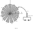
- FIG. 3b is a schematic diagram of sector equal division of a cubic obstacle model in one embodiment of a method of obstacle avoidance of a robot of the disclosure.
- the model block No. 1 has a deflection angle of 11.25 degrees from the positive direction of the axis X
- FIG. 3c is a schematic diagram of selection of a model portion in one embodiment of a method of obstacle avoidance of a robot of the disclosure.
- FIG. 3d is a schematic diagram of calculation of a shortest distance vector in one embodiment of a method of obstacle avoidance of a robot of the disclosure.
- the range of the obstacle blocks has been narrowed as (1,2,31,32), so that the shortest distance points between the robot and the obstacle may be directly calculated by adopting the GJK algorithm; as shown in FIG.
- the step S30 includes: the system of controlling obstacle avoidance of the robot analyzes whether to avoid the obstacle or not according to the calculated shortest distance; if the calculated shortest distance is greater than a preset distance threshold value, the system determines that no obstacle avoidance is needed, or if the calculated shortest distance is less than or equal to the preset distance threshold value, the system determines that obstacle avoidance is needed. If the obstacle avoidance is needed, the system of controlling obstacle avoidance of the robot calculates the due movement direction of the current robot according to the acquired positioning data, the calculated shortest distance and the 3D model of the obstacle, and controls the movement posture of the robot according to the calculated movement direction.
- the step that the system calculates the due movement direction of the current robot according to the acquired positioning data, the calculated shortest distance and the 3D model of the obstacle includes:
- FIG. 4 is a schematic diagram of determination of an effective blocking region in one embodiment of a method of obstacle avoidance of a robot of the disclosure.
- the predetermined projection analysis rule is as follows:
- the first preset type of obstacle avoidance parameter is the virtual repulsive force
- the second preset type of obstacle avoidance parameter is the virtual attractive force.
- d the vector of the shortest distance between the robot and the obstacle
- S is the area of the effective blocking region
- F r is the virtual repulsive force from the obstacle to the robot
- f ( d , S ) represents a relational expression that the shortest distance vector and the area of the effective blocking region are converted into the virtual repulsive force from the obstacle to the robot.
- F t is the virtual attractive force from the target position to the robot
- k t represents a preset attractive force coefficient
- d t represents a distance between the target position and the current position of the robot
- the direction of the virtual attractive force faces to the target position.
- a system of controlling obstacle avoidance of a robot is further provided.
- this figure shows a schematic diagram of an operation environment of a preferred embodiment of a system 10 of controlling obstacle avoidance of the disclosure.
- the system 10 of controlling obstacle avoidance is installed and operated in the robot 1.
- the robot 1 may include, but not limited to, a memory 11, a processor 12 and a display 13.
- FIG. 1 shows the robot 1 having assemblies from 11 to 13, but it should be understood that not all the assemblies listed are required to be implemented, and more or fewer assemblies may be implemented instead.
- the memory 11 includes an internal memory and at least one type of readable storage medium.
- the internal memory provides a buffer for operation of the robot 1;
- the readable storage medium may be a non-volatile storage medium, such as a flash memory, a hard disk, a multimedia card and a card memory.
- the readable storage medium may be an internal storage unit of the robot 1, for example the hard disk or the internal memory of the robot 1.
- the readable storage medium also may be external storage equipment of the robot 1, for example a plug-in type hard disk, a Smart Media Card (SMC), a Secure Digital (SD) card, a Flash Card (FC) and the like which are equipped on the robot.
- SMC Smart Media Card
- SD Secure Digital
- FC Flash Card
- the readable storage medium of the memory 11 is generally used for storing application software installed in the robot 1 and all types of data, for example a program code of the system 10 of controlling obstacle avoidance and the like.
- the memory 11 may be also used for temporarily storing data which have been output or are about to be output.
- the processor 12 may be a Central Processing Unit (CPU), a micro processor or other data processing chips, and is used for operating the program code stored in the memory 11 or processing the data.
- the processor 12 executes the system 10 of controlling obstacle avoidance to implement any step of the method of obstacle avoidance of the robot.
- the display 13 may be an Light-Emitting Diode (LED) display, a liquid crystal display, a touch liquid crystal display, an Organic Light-Emitting Diode (OLED) touch device and the like.
- the display 13 is used for displaying information processed in the robot 1 and displaying a visual user interface such as an application menu interface and an application icon interface.
- the assemblies 11 to 13 of the robot 1 communicate with one another through a system bus.
- the system 10 of controlling obstacle avoidance may be partitioned into a determination module 01, a calculation module 02 and a control module 03.
- the modules in the disclosure are a series of computer program instruction segments capable of completing specific functions, and are used for describing execution processes of the system 10 of controlling obstacle avoidance in the robot 1.
- the processor 12 executes the computer program instruction segments of all the modules of the system 10 of controlling obstacle avoidance, any step of the above-mentioned method of obstacle avoidance of the robot may be implemented on the basis of operation and functions which are realized by all the computer program instruction segments. Specific introductions of the operation and the functions which are realized by the determination module 01, the calculation module 02 and the control module 03 will be described below.
- the determination module 01 is used for acquiring current positioning data (for example an indoor position, a posture and the like) of the robot in real time or regularly (for example every 2 seconds), and determining whether an obstacle, which is spaced from a current position at a distance shorter than a preset distance, exists in a path from the current position to a target position or not according to the current positioning data and position data of all obstacles in a predetermined moving region. For example, distances from all the obstacles in the predetermined moving region may be positioned and judged via an own sensor of the robot.
- a proximity sensor such as an ultrasonic sensor, an infrared sensor and a laser sensor
- a proximity sensor may be installed on the robot to judge whether the obstacle, which is spaced from the current position at the distance shorter than the preset distance, exists in the path from the current position of the robot to the target position or not.
- the calculation module 02 is used for calculating the shortest distance between the robot and the obstacle according to the acquired positioning data, a predetermined 3D model of the robot and a predetermined 3D model of the obstacle if the obstacle, which is spaced from the current position at the distance shorter than the preset distance, exists.
- the robot After the distances between the current position of the robot and all the obstacles in the predetermined moving region are detected, but if no obstacle, which is spaced from the current position at the distance shorter than the preset distance, exists, the robot goes on moving along the path to the target position, and distances between the robot and all the obstacles in the moving region are detected in real time or regularly.
- the shortest distance between the robot and the obstacle is calculated according to the acquired positioning data, the predetermined 3D model of the robot and the predetermined 3D model of the obstacle to judge whether the robot in a three-dimensional space may collide with the obstacle or not during moving along the path to the target position by using the shortest distance, thereby realizing that an obstacle may be detected at a height plane where the sensor of the robot is located, and a potential obstacle in the three-dimensional space may be also detected, that is, the potential obstacles in all directions in the three-dimensional space may be all detected in a direction where the sensor is installed on the robot and in other directions where no sensors are installed on the robot, wherein the predetermined 3D model of the robot and the 3D models of all the obstacles in the moving region may be pre-stored in a storage unit of the robot, or may be obtained by the robot which accesses an Internet of things system server through a wireless communication unit, and no limitation will be made here.
- the control module 03 is used for calculating a due movement direction of the current robot according to the acquired positioning data, the calculated shortest distance and the 3D model of the obstacle, and controlling a movement posture of the robot according to the calculated movement direction to avoid the potential obstacles in all directions in the three-dimensional space, thus effectively controlling the robot to avoid the obstacles during moving along the path to the target position.
- the shortest distance between the robot and the obstacle in the three-dimensional space is calculated according to the current positioning data of the robot, the predetermined 3D model of the robot and the predetermined 3D model of the obstacle, and the due movement direction of the current robot is also calculated, so that the movement posture of the robot may be controlled.
- the movement direction of the robot may be controlled via the shortest distance between the robot and the obstacle in the three-dimensional space, thus realizing detection and avoidance of obstacles in all directions of the robot in the three-dimensional space, and effectively controlling the robot to avoid the obstacles.
- the calculation module 02 is also used for: preprocessing the predetermined 3D model of the robot and the 3D model of the obstacle, and calculating the shortest distance between the robot and the obstacle by using a predetermined distance calculation rule according to the acquired positioning data, preprocessed robot 3D model data and preprocessed obstacle 3D model data.
- the 3D models of the robot and the obstacle may be preprocessed, for example they may be converted into convex bodies so as to calculate the shortest distance more accurately and quickly in the subsequent step.
- the calculation module 02 is also used for: for each joint of the robot, finding out a minimum convex polyhedron surrounding each joint by directly using a predetermined algorithm (for example a QuickHull algorithm) to convert the robot non-convex model into a convex model.
- a predetermined algorithm for example a QuickHull algorithm
- the first one is that a convex bounding box of a non-convex polyhedron is built, and then is converted into a convex body for collision detection
- the second one is that the non-convex polyhedron is subjected to convex decomposition to convert the non-convex model into a plurality of convex bodies for collision detection
- the third one is that the obstacle 3D model is subjected to sector equal division (namely sector subdivision), and then single sectors subjected to the equal division are subjected to convex decomposition.
- the third mode of sector equal division first and then convex decomposition is higher in calculation speed and higher in calculation precision than the first two modes.
- the calculation module 02 is also used for: building a spherical bounding box of the obstacle 3D model to be subjected to sector equal division, and finding out the sphere center of the spherical bounding box; setting an initial sector equal division plane passing through the sphere center, and rotating it for multiple times around the sphere center according to a preset rotating angle to equally divide the spherical bounding box into n sector portions, wherein the n sector portions of the spherical bounding box serve as n model portions of the obstacle 3D model.
- the operation may include the following steps:
- the calculation module 02 is also used for: carrying out surface triangulation on the obstacle 3D model by adopting a Delaunay triangulation algorithm to generate a triangular patch (lug) set, and constructing a convex block corresponding to each triangular patch for each triangular patch.
- the triangular patches with zero thickness are stretched on the basis of a preset thickness in directions of their plane normal vectors, and then are changed into convex blocks.
- the predetermined distance calculation rule includes:
- the predetermined selection algorithm includes:
- the robot does not have arms and other movement joints, but only has a chassis movement;
- the robot 3D model is 1,500 mm in height and has a movement chassis radius of 320 mm, and the obstacle 3D model is a simple cubic model with the size of 2,200 mm ⁇ 2,200 mm ⁇ 1,000 mm; and under the obstacle model coordinate system, the current coordinates of the robot are (1800, -100).
- the model block No. 1 has a deflection angle of 11.25 degrees from the positive direction of the axis X
- the model block No. i has a deflection angle of i ⁇ (360/32) degrees from the positive direction of the axis X.
- control module 03 is also used for: analyzing whether to avoid the obstacle or not according to the calculated shortest distance; if the calculated shortest distance is greater than a preset distance threshold value, determining that no obstacle avoidance is needed, or if the calculated shortest distance is less than or equal to the preset distance threshold value, determining that obstacle avoidance is needed; and if the obstacle avoidance is needed, calculating the due movement direction of the current robot according to the acquired positioning data, the calculated shortest distance and the 3D model of the obstacle, and controlling the movement posture of the robot according to the calculated movement direction.
- control module 03 is also used for:
- the predetermined projection analysis rule is as follows:
- the control module 03 is also used for:
- d the vector of the shortest distance between the robot and the obstacle
- S is the area of the effective blocking region
- F r is the virtual repulsive force from the obstacle to the robot
- f ( d , S ) represents a relational expression that the shortest distance vector and the area of the effective blocking region are converted into the virtual repulsive force from the obstacle to the robot.
- F t is the virtual attractive force from the target position to the robot
- k t represents a preset attractive force coefficient
- d t represents a distance between the target position and the current position of the robot
- the direction of the virtual attractive force faces to the target position.
- a computer readable storage medium is further provided.
- the computer readable storage medium stores a system of controlling obstacle avoidance of a robot.
- the system of controlling obstacle avoidance of the robot may be executed by at least one processor to implement the following operations:
- step S20 includes: Step S201, the predetermined 3D model of the robot and the 3D model of the obstacle are preprocessed.
- Step S202 the shortest distance between the robot and the obstacle is calculated by using a predetermined distance calculation rule according to the acquired positioning data, preprocessed robot 3D model data and preprocessed obstacle 3D model data.
- the preprocessing of the robot 3D model in the step S201 includes: for each joint of the robot, a minimum convex polyhedron surrounding each joint is found out by directly using a predetermined algorithm (for example a QuickHull algorithm) to convert the robot non-convex model into a convex model.
- a predetermined algorithm for example a QuickHull algorithm
- the first one is that a convex bounding box of a non-convex polyhedron is built, and then is converted into a convex body for collision detection
- the second one is that the non-convex polyhedron is subjected to convex decomposition to convert the non-convex model into a plurality of convex bodies for collision detection
- the third one is that the obstacle 3D model is subjected to sector equal division (namely sector subdivision), and then single sectors subjected to the equal division are subjected to convex decomposition.
- the third mode of sector equal division first and then convex decomposition is higher in calculation speed and higher in calculation precision than the first two modes.
- step that the obstacle 3D model is subjected to sector equal division includes:
- the step that the single sectors subjected to equal division are subjected to convex decomposition includes: the obstacle 3D model is subjected to surface triangulation by adopting a Delaunay triangulation algorithm to generate a triangular patch (lug) set, and a convex block corresponding to each triangular patch is constructed for each triangular patch.
- the triangular patches with zero thickness are stretched on the basis of a preset thickness in directions of their plane normal vectors, and then are changed into convex blocks.
- the predetermined distance calculation rule includes:
- the step S30 includes: the system of controlling obstacle avoidance of the robot analyzes whether to avoid the obstacle or not according to the calculated shortest distance; if the calculated shortest distance is greater than a preset distance threshold value, the system determines that no obstacle avoidance is needed, or if the calculated shortest distance is less than or equal to the preset distance threshold value, the system determines that obstacle avoidance is needed. If the obstacle avoidance is needed, the system of controlling obstacle avoidance of the robot calculates the due movement direction of the current robot according to the acquired positioning data, the calculated shortest distance and the 3D model of the obstacle, and controls the movement posture of the robot according to the calculated movement direction.
- the step that the system calculates the due movement direction of the current robot according to the acquired positioning data, the calculated shortest distance and the 3D model of the obstacle includes:
- predetermined projection analysis rule is as follows:
- the first preset type of obstacle avoidance parameter is the virtual repulsive force
- the second preset type of obstacle avoidance parameter is the virtual attractive force.
- d the vector of the shortest distance between the robot and the obstacle
- S is the area of the effective blocking region
- F r is the virtual repulsive force from the obstacle to the robot
- f ( d , S ) represents a relational expression that the shortest distance vector and the area of the effective blocking region are converted into the virtual repulsive force from the obstacle to the robot.
- F t is the virtual attractive force from the target position to the robot
- k t represents a preset attractive force coefficient
- d t represents a distance between the target position and the current position of the robot
- the direction of the virtual attractive force faces to the target position.
Landscapes
- Engineering & Computer Science (AREA)
- Physics & Mathematics (AREA)
- General Physics & Mathematics (AREA)
- Radar, Positioning & Navigation (AREA)
- Remote Sensing (AREA)
- Automation & Control Theory (AREA)
- Aviation & Aerospace Engineering (AREA)
- Robotics (AREA)
- Mechanical Engineering (AREA)
- Electromagnetism (AREA)
- Computer Graphics (AREA)
- Theoretical Computer Science (AREA)
- Software Systems (AREA)
- Geometry (AREA)
- Acoustics & Sound (AREA)
- Manipulator (AREA)
- Control Of Position, Course, Altitude, Or Attitude Of Moving Bodies (AREA)
Claims (14)
- Un système de contrôle d'évitement d'obstacles pour robots, comprenant les éléments suivants:un module de détermination (01), utilisé pour acquérir les données de positionnement actuel du robot (1) en temps réel ou régulièrement, et déterminer s'il existe ou non un obstacle, à une distance de la position actuelle plus courte que la distance prédéfinie, sur une trajectoire à partir de la position actuelle vers la position cible, conformément aux données de positionnement actuel et aux données de position de tous les obstacles situés sur une région de déplacement prédéfinie;un module de calcul (02), utilisé pour calculer la distance la plus courte entre le robot (1) et l'obstacle, conformément aux données de positionnement acquises, au modèle 3D prédéfini du robot (1) et au modèle 3D prédéfini de l'obstacle, si l'obstacle, qui est séparé de la position actuelle par une distance plus courte que la distance prédéfinie, existe;un module de contrôle (03), utilisé pour calculer la direction de déplacement prévue du robot (1), conformément aux données de positionnement acquises, à la distance la plus courte calculée et au modèle 3D de l'obstacle; et contrôler la posture de déplacement du robot (1), conformément à la direction de déplacement calculée pour éviter des obstacles potentiels; où le module de contrôle (03) est utilisé en outre pour:projeter le modèle 3D du robot (01) et le modèle 3D de l'obstacle sur le même plan du système de coordonnées;calculer une surface d'une région de blocage effectif d'une projection du modèle 3D de l'obstacle concernant la position actuelle du robot (1) et la position cible, conformément à une règle d'analyse de projection prédéterminée et aux coordonnées de tous les points sur le contour extérieur d'une région de projection, obtenues au moyen de la projection du modèle 3D de l'obstacle sur le plan du système de coordonnées;déterminer un premier type prédéfini de paramètre d'évitement d'obstacle, conformément à la distance la plus courte calculée et à la surface de la région de blocage effectif; déterminer un deuxième type prédéfini de paramètre d'évitement d'obstacle, conformément à la distance existante entre la position cible et la position actuelle du robot (1); et déterminer la direction de déplacement prévue actuelle du robot, conformément au premier type prédéfini de paramètre d'évitement d'obstacle et au deuxième type prédéfini de paramètre d'évitement d'obstacle.
- Le système conformément à la revendication 1, où le module de calcul (02) est en outre utilisé pour:prétraiter le modèle 3D prédéterminé du robot (1) et le modèle 3D de l'obstacle, et pour chaque articulation du robot (1), trouver un polyèdre convexe minimum entourant chaque articulation, en utilisant directement un algorithme prédéterminé pour convertir le modèle non-convexe du robot en un modèle convexe; effectuer la répartition égale de secteur sur le modèle 3D de l'obstacle, et ensuite effectuer la décomposition convexe sur les secteurs individuels sujets à une répartition égale;calculer la distance la plus courte entre le robot (1) et l'obstacle, en utilisant une règle de calcul de distance prédéterminée, conformément aux données de positionnement acquises, aux données du modèle 3D du robot prétraitées et aux données du modèle 3D de l'obstacle prétraitées.
- Le système conformément à la revendication 2, où le module de calcul (02) est en outre utilisé pour:construire une boîte englobant sphérique du modèle 3D de l'obstacle pour être sujette à la répartition égale de secteur, et trouver le centre de la sphère de la boîte englobant sphérique;établir un plan initial de répartition égale de secteur qui passe à travers du centre de la sphère, et tourner le plan plusieurs fois autour du centre de la sphère, conformément à un angle de rotation prédéfini pour faire une répartition égale de la boîte englobant sphérique en n portions du secteur, où les n portions du secteur de la boîte englobant sphérique servent comme n portions du modèle 3D de l'obstacle.
- Le système conformément à la revendication 2, où la règle de calcul de la distance prédéterminée comprend les pas suivants:sélectionner toutes les portions du modèle obtenues par la répartition égale de secteur du modèle 3D de l'obstacle, conformément aux données de positionnement actuel du robot (1) et à l'algorithme de sélection prédéterminé pour sélectionner une portion du modèle sujette au calcul de distance;calculer la distance la plus courte entre le robot (1) et la portion du modèle sélectionnée en utilisant un algorithme de calcul de distance prédéterminé, conformément aux données de positionnement acquises et à la portion du modèle sélectionnée, où la distance la plus courte est celle située entre le robot (1) et l'obstacle;où l'algorithme de sélection prédéterminé comprend les pas suivants:considérer respectivement les n portions du modèle obtenues par la répartition égale de secteur du modèle 3D de l'obstacle comme n nœuds de l'obstacle, et construire une table de hashage dans laquelle l'association clé-valeur correspond respectivement à des angles de déflection du plan initial de répartition égale de secteur pour effectuer la gestion des nœuds du modèle;numéroter toutes les portions du modèle, et, en fonction des chiffres, créer une relation de correspondance des angles de déflection d'une portion du modèle du secteur N° i, où la fonction de hashage représentant la relation de correspondance des angles de déflection est définie comme suit :
 où Hash(i) représente un angle de déflection entre la portion du modèle du secteur N° i et l'axe x positif du système de coordonnées d'un obstacle:créer une équation cinématique du robot (1), et calculer les positions et les postures de toutes les articulations du robot, conformément à l'équation cinématique créée, où l'équation cinématique est comme suit:
 où Ak (k=1, 2, .., i) est une matrice de transformation homogène parmi les systèmes de coordonnées des articulations du robot (1) ; A0 représente la matrice de position actuelle du robot (1) et Ti représente la position et la posture de l'i ième articulation relative au système de coordonnés du robot;calculer les coordonnées Qi (x, y, z) de toutes les articulations liées au système de coordonnées du robot pendant le déplacement du robot (1), conformément à Ti, et calculer la matrice de transformation Tr pour transformer le système de coordonnées du robot en système de coordonnées de l'obstacle, où les coordonnées Qi (xt, yt, zt ) de chaque articulation du robot liée au système de coordonnées de l'obstacle sont comme suit:
 l'angle de déflection α de chaque articulation liée au système de coordonnées de l'obstacle est obtenu à travers la formule suivante:
 et les portions du modèle numérotées correspondantes sont calculées conformément à l'angle de déflection α et à la fonction de hashage Hash(i), et les portions du modèle qui seront sujettes au calcul de la distance sont sélectionnées sur la base des portions du modèle numérotées de manière correspondante.
 - Une méthode de contrôle d'évitement d'obstacles pour robots, comprenant les pas suivants:acquérir les données de positionnement actuel du robot (1) en temps réel ou régulièrement, et déterminer s'il existe ou non un obstacle à une distance de la position actuelle plus courte que la distance prédéfinie sur une trajectoire à partir de la position actuelle vers la position cible, conformément aux données de positionnement actuel et aux données de position de tous les obstacles situés sur une région de déplacement prédéfinie;si l'obstacle, qui est séparé de la position actuelle d'une distance plus courte que la distance prédéfinie, existe, calculer la distance la plus courte entre le robot (1) et l'obstacle conformément aux données de positionnement acquises, au modèle 3D prédéterminé du robot (1) et au modèle 3D prédéterminé de l'obstacle;calculer la direction de déplacement prévue du robot actuel, conformément aux données de positionnement acquises, à la distance la plus courte calculée et au modèle 3D de l'obstacle, où l'opération de calculer la direction de déplacement prévue comprend les pas suivants:projeter le modèle 3D du robot (1) et le modèle 3D de l'obstacle sur le même plan du système de coordonnées;calculer une surface d'une région de blocage effectif d'une projection du modèle 3D de l'obstacle relative à la position actuelle du robot (1) et à la position cible, conformément à une règle d'analyse des projections prédéterminée et aux coordonnées de tous les points sur le contour extérieur d'une région de projection obtenues en projetant le modèle 3D de l'obstacle sur le plan du système de coordonnées;déterminer un premier type prédéfini du paramètre d'évitement d'obstacle, conformément à la distance la plus courte calculée et à la surface de la région de blocage effectif; déterminer un deuxième type prédéfini de paramètre d'évitement d'obstacle, conformément à la distance entre la position cible et la position actuelle du robot (1) ; et déterminer la direction de déplacement prévue actuelle du robot, conformément au premier type prédéfini de paramètre d'évitement d'obstacle et au deuxième type prédéfini de paramètre d'évitement d'obstacle; etcontrôler la posture de déplacement du robot (1), conformément à la direction de déplacement calculée pour éviter des obstacles potentiels.
- La méthode conformément à la revendication 5, où l'opération de calcul de la distance la plus courte comprend les pas suivants:prétraiter le modèle 3D prédéterminé du robot (1) et le modèle 3D de l'obstacle, et, pour chaque articulation du robot (1), trouver un polyèdre convexe minimum entourant chaque articulation, en utilisant directement un algorithme prédéterminé pour convertir le modèle non-convexe du robot en un modèle convexe;effectuer la répartition égale de secteur sur le modèle 3D de l'obstacle, et ensuite effectuer la décomposition convexe sur les secteurs individuels sujets à une répartition égale ;calculer la distance la plus courte entre le robot (1) et l'obstacle, en utilisant une règle de calcul de distance prédéterminée conformément aux données de positionnement acquises, aux données du modèle 3D du robot prétraitées et aux données du modèle 3D de l'obstacle prétraitées.
- La méthode conformément à la revendication 6, où l'opération de calcul de la distance la plus courte comprend en outre les pas suivants:construire une boîte englobant sphérique du modèle 3D de l'obstacle pout être sujette à la répartition égale de secteur, et trouver le centre de la sphère de la boîte englobant sphérique;établir un plan initial de répartition égale de secteur qui passe à travers du centre de la sphère, et tourner le plan plusieurs fois autour du centre de la sphère, conformément à un angle de rotation prédéfini pour faire une répartition égale de la boîte englobant sphérique en portions du secteur, où les n portions de la boîte englobant sphérique servent comme n portions du modèle 3D de l'obstacle.
- La méthode conformément à la revendication 6, où la règle de calcul de la distance prédéterminée comprend les pas suivants:sélectionner toutes les portions du modèle obtenues par la répartition égale de secteur du modèle 3D de l'obstacle, conformément aux données de positionnement actuel du robot (1) et à l'algorithme de sélection prédétermine pour sélectionner une portion du modèle sujette au calcul de distance;calculer la distance la plus courte entre le robot (1) et la portion du modèle sélectionnée en utilisant un algorithme de calcul de distance prédéterminé, conformément aux données de positionnement acquises et à la portion du modèle sélectionnée, où la distance la plus courte est celle située entre le robot (1) et l'obstacle;où l'algorithme de sélection prédéterminé comprend les pas suivants:considérer respectivement les n portions du modèle obtenues par la répartition égale de secteur du modèle 3D de l'obstacle comme n nœuds de l'obstacle, et construire une table de hashage dans laquelle l'association clé-valeur correspond respectivement à des angles de déflection du plan initial de répartition égale de secteur pour effectuer la gestion des nœuds du modèle;numéroter toutes les portions du modèle, et en fonction des chiffres, créer une relation de correspondance des angles de déflection d'une portion du modèle du secteur N° i, où la fonction de hashage représentant la relation de correspondance des angles de déflection est définie comme suit :
 où Hash(i) représente un angle de déflection entre la portion du modèle du secteur N° i et l'axe x positif du système de coordonnées d'un obstacle:créer une équation cinématique du robot, et calculer les positions et les postures de toutes les articulations du robot conformément à l'équation cinématique créée, où l'équation cinématique est comme suit:
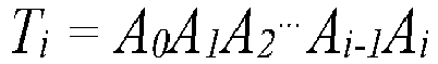 où Ak (k=1, 2, .., i) est une matrice de transformation homogène parmi les systèmes de coordination des articulations du robot; A0 représente la matrice de position actuelle du robot (1) et Ti représente la position et la posture de l'iième articulation relative au système de coordonnées du robot;calculer les coordonnées Qi (x, y, z) de toutes les articulations liées au système de coordonnées du robot pendant le déplacement du robot (1), conformément à Ti , et calculer la matrice de transformation Tr pour transformer le système de coordonnées du robot en système de coordonnées de l'obstacle, où les coordonnées Qi (xt, yt, zt) de chaque articulation du robot liée au système de coordonnées de l'obstacle sont comme suit:
 l'angle de déflection α de chaque articulation liée au système de coordonnées de l'obstacle est obtenu à travers la formule suivante:
 et les portions du modèle numérotées correspondantes sont calculées conformément à l'angle de déflection α et à la fonction de hashage Hash(i), et les portions du modèle qui seront sujettes au calcul de la distance sont sélectionnées sur la base des portions du modèle numérotées de manière correspondante.
 - La méthode conformément à la revendication 5, où la règle d'analyse des projections prédéterminée est comme suit:établir un point de position P1 sur le plan du système de coordonnées pour représenter la position actuelle du robot, où un point de position P2 est la position cible, une région de projection P3 est une projection du modèle 3D de l'obstacle sur le plan du système de coordonnées et P1 et P2 sont connectées sur le plan du système de coordonnées pour obtenir une ligne droite J ;si la ligne droite J et la région de projection P3 n'ont pas une intersection ou elles n'en ont qu'une seule, déterminer qu'il n'existe pas de région de blocage effectif;si la ligne droite J et la région de projection P3 ont plus d'une intersection, partitionner la projection en deux portions par la ligne droite J; trouver un point Ps sur la région de projection P3, faire une ligne perpendiculaire à la ligne droite J de manière à passer à travers Ps, et définir une intersection entre la ligne perpendiculaire et la ligne droite J, comme Pj , et obtenir ainsi un vecteur
PjPs ; calculer un angle θ inclus entre led vecteur de la distance la plus courte et le vecteur et le vecteurPjPs ; si l' angle θ est un angle aigu, déterminer que la région où le point Ps est situé est la région du blocage effectif, ou si l' angle θ n'est pas un angle aigu, déterminer que la région où le point Ps est situé n'est pas une région de blocage effectif. - La méthode conformément à la revendication 5, où le premier type prédéfini du paramètre d'évitement d'obstacle est une force de répulsion virtuelle, et le deuxième type prédéfini du paramètre d'évitement d'obstacle est une force d'attraction virtuelle ; et l'opération de calcul d'une direction de déplacement prévue comprend en outre les pas suivants:calculer la force de répulsion virtuelle agissant sur le robot (1), en utilisant une première règle de calcul conformément à la distance la plus courte calculée et à la zone de la région de blocage effectif;calculer la force d'attraction virtuelle agissant sur le robot (1), en utilisant une deuxième règle de calcul conformément à la distance entre la position actuelle et la position du point cible;calculer la direction de la force résultante de la force d'attraction virtuelle et de la force de répulsion virtuelle, qui sert comme direction de déplacement actuelle du robot (1).
- La méthode conformément à la revendication 10, où la première règle de calcul est comme suit:définir le vecteur de la distance la plus courte entre le robot (1) et l'obstacle comme
d; définir la surface de la région de blocage effectif comme S, et définir la force de répulsion virtuelle à partir de l'obstacle vers le robot commeF r ; où la formule de calcul est la suivante: où
oùd est le vecteur de la distance la plus courte entre le robot (1) et l'obstacle; S est la surface de la région de blocage effectif ;Fr est la force de répulsion virtuelle à partir de l'obstacle vers le robot; kr et br représentent la force de répulsion virtuelle prédéfinie; So représente une valeur seuil de la surface prédéfinie de la région de blocage effectif ; d0 représente une valeur seuil de la distance prédéfinie ; et la direction deFr est la même que celle de la distance la plus courte. - La méthode conformément à la revendication 10, où la deuxième règle de calcul est la suivante:
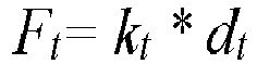
F t la force d'attraction virtuelle à partir de la position cible vers le robot (1); kt représente un coefficient de force d'attraction prédéfini; dt est la distance entre la position cible et la position actuelle du robot (1); et la direction fait face àF t la position cible. - Un robot (1), comprenant un processeur (12) et une mémoire (11), où la mémoire (11) stocke un système (10) de contrôle de l'évitement d'obstacles pour un robot (1), et le système (10) est exécuté par le processeur (12) en vue d'effectuer les opérations contenues dans la méthode des revendications 5 à 12.
- Un support de stockage lisible par ordinateur, qui stocke un système (10) de contrôle de l'évitement d'obstacles pour un robot (1), où le système (10) est exécuté au moins par un processeur (12) pour effectuer les opérations contenues dans la méthode des revendications 5 à 12.
Applications Claiming Priority (2)
| Application Number | Priority Date | Filing Date | Title |
|---|---|---|---|
| CN201710186581.6A CN107688342B (zh) | 2017-03-27 | 2017-03-27 | 机器人的避障控制系统及方法 |
| PCT/CN2017/091368 WO2018176668A1 (fr) | 2017-03-27 | 2017-06-30 | Procédé et système de commande d'évitement d'obstacles de robot, robot et support d'informations |
Publications (3)
| Publication Number | Publication Date |
|---|---|
| EP3410246A1 EP3410246A1 (fr) | 2018-12-05 |
| EP3410246A4 EP3410246A4 (fr) | 2019-11-06 |
| EP3410246B1 true EP3410246B1 (fr) | 2021-06-23 |
Family
ID=61152364
Family Applications (1)
| Application Number | Title | Priority Date | Filing Date |
|---|---|---|---|
| EP17897209.7A Active EP3410246B1 (fr) | 2017-03-27 | 2017-06-30 | Procédé et système de commande d'évitement d'obstacles de robot, robot et support d'informations |
Country Status (9)
| Country | Link |
|---|---|
| US (1) | US11059174B2 (fr) |
| EP (1) | EP3410246B1 (fr) |
| JP (1) | JP6716178B2 (fr) |
| KR (1) | KR102170928B1 (fr) |
| CN (1) | CN107688342B (fr) |
| AU (1) | AU2017404562B2 (fr) |
| SG (1) | SG11201809892QA (fr) |
| TW (1) | TWI662388B (fr) |
| WO (1) | WO2018176668A1 (fr) |
Families Citing this family (69)
| Publication number | Priority date | Publication date | Assignee | Title |
|---|---|---|---|---|
| CN108717302B (zh) * | 2018-05-14 | 2021-06-25 | 平安科技(深圳)有限公司 | 机器人跟随人物方法、装置及存储介质、机器人 |
| CN109461185B (zh) * | 2018-09-10 | 2021-08-17 | 西北工业大学 | 一种适用于复杂场景的机器人目标主动避障方法 |
| CN109465835A (zh) * | 2018-09-25 | 2019-03-15 | 华中科技大学 | 一种动态环境下双臂服务机器人作业的事前安全预测方法 |
| TWI721324B (zh) * | 2018-10-10 | 2021-03-11 | 鴻海精密工業股份有限公司 | 電子裝置及立體物體的判斷方法 |
| CN109284574B (zh) * | 2018-10-25 | 2022-12-09 | 西安科技大学 | 一种串联桁架结构体系非概率可靠性分析方法 |
| KR102190101B1 (ko) * | 2019-03-08 | 2020-12-11 | (주)아이로텍 | 로봇의 장애물 충돌 회피를 위한 경로 안내툴 표시 방법 및 이를 이용한 충돌 회피 시뮬레이션 시스템 |
| CN110442126A (zh) * | 2019-07-15 | 2019-11-12 | 北京三快在线科技有限公司 | 一种移动机器人及其避障方法 |
| CN110390829A (zh) * | 2019-07-30 | 2019-10-29 | 北京百度网讯科技有限公司 | 交通信号灯识别的方法及装置 |
| CN112445209A (zh) * | 2019-08-15 | 2021-03-05 | 纳恩博(北京)科技有限公司 | 机器人的控制方法和机器人、存储介质及电子装置 |
| CN110727273B (zh) * | 2019-11-13 | 2025-04-18 | 北京邮电大学 | 多球形机器人编队形成过程路径规划算法 |
| CN111046743B (zh) * | 2019-11-21 | 2023-05-05 | 新奇点智能科技集团有限公司 | 一种障碍物信息标注方法、装置、电子设备和存储介质 |
| CN111207750A (zh) * | 2019-12-31 | 2020-05-29 | 合肥赛为智能有限公司 | 一种机器人动态路径规划方法 |
| CN111168675B (zh) * | 2020-01-08 | 2021-09-03 | 北京航空航天大学 | 一种家用服务机器人的机械臂动态避障运动规划方法 |
| CN111449666B (zh) * | 2020-03-09 | 2023-07-04 | 北京东软医疗设备有限公司 | 距离监测方法、装置、血管机、电子设备及存储介质 |
| JP7519792B2 (ja) * | 2020-03-19 | 2024-07-22 | 本田技研工業株式会社 | 制御装置、制御方法およびプログラム |
| CN111571582B (zh) * | 2020-04-02 | 2023-02-28 | 上海钧控机器人有限公司 | 一种艾灸机器人人机安全监控系统及监控方法 |
| CN111427355B (zh) * | 2020-04-13 | 2023-05-02 | 京东科技信息技术有限公司 | 障碍物数据处理方法、装置、设备及存储介质 |
| JP7447670B2 (ja) * | 2020-05-15 | 2024-03-12 | トヨタ自動車株式会社 | 自律移動装置制御システム、その制御方法及びその制御プログラム |
| US11292132B2 (en) * | 2020-05-26 | 2022-04-05 | Edda Technology, Inc. | Robot path planning method with static and dynamic collision avoidance in an uncertain environment |
| CN111857126A (zh) * | 2020-05-29 | 2020-10-30 | 深圳市银星智能科技股份有限公司 | 一种机器人避障方法、机器人以及存储介质 |
| CN111958590B (zh) * | 2020-07-20 | 2021-09-28 | 佛山科学技术学院 | 一种复杂三维环境中机械臂防碰撞方法及系统 |
| JP7409264B2 (ja) * | 2020-08-27 | 2024-01-09 | トヨタ自動車株式会社 | 運搬システム、運搬方法、及びプログラム |
| CN112148013B (zh) * | 2020-09-25 | 2024-08-09 | 深圳优地科技有限公司 | 机器人避障方法、机器人及存储介质 |
| CN112415532B (zh) * | 2020-11-30 | 2022-10-21 | 上海炬佑智能科技有限公司 | 灰尘检测方法、距离检测装置以及电子设备 |
| CN112704878B (zh) * | 2020-12-31 | 2023-04-18 | 深圳市乙亥互娱信息科技有限公司 | 集群游戏中的单位位置调整方法、系统、设备及存储介质 |
| CN114742960B (zh) * | 2021-02-08 | 2025-11-25 | 魔法原子机器人科技(无锡)有限公司 | 目标对象的躲避方法及装置、存储介质、电子装置 |
| CN113119109A (zh) * | 2021-03-16 | 2021-07-16 | 上海交通大学 | 基于伪距离函数的工业机器人路径规划方法和系统 |
| CN113211495B (zh) * | 2021-04-12 | 2024-09-06 | 北京航天飞行控制中心 | 一种机械臂碰撞检测方法、系统、存储介质和机械臂 |
| CN113110594B (zh) * | 2021-05-08 | 2022-05-17 | 北京三快在线科技有限公司 | 控制无人机避障的方法、装置、存储介质及无人机 |
| CN113282984A (zh) * | 2021-05-21 | 2021-08-20 | 长安大学 | 一种公共场所人员应急疏散模拟方法 |
| CN113459090A (zh) * | 2021-06-15 | 2021-10-01 | 中国农业大学 | 码垛机器人的智能避障方法、电子设备及介质 |
| US11753045B2 (en) * | 2021-06-22 | 2023-09-12 | Waymo Llc | Modeling positional uncertainty of moving objects using precomputed polygons |
| CN113601497B (zh) * | 2021-07-09 | 2024-02-06 | 广东博智林机器人有限公司 | 一种方法、装置、机器人及存储介质 |
| CN113752265B (zh) * | 2021-10-13 | 2024-01-05 | 国网山西省电力公司超高压变电分公司 | 一种机械臂避障路径规划方法、系统及装置 |
| KR102563074B1 (ko) * | 2021-10-20 | 2023-08-02 | 금오공과대학교 산학협력단 | 차동 구동형 이동로봇의 운동역학을 고려한 장애물 회피 및 경로 추종방법 |
| CN114035569B (zh) * | 2021-11-09 | 2023-06-27 | 中国民航大学 | 一种航站楼载人机器人路径拓展通行方法 |
| CN114792019B (zh) * | 2021-11-30 | 2024-08-27 | 广东天凛高新科技有限公司 | 机器人穿插交互建墙系统 |
| CN114161047B (zh) * | 2021-12-23 | 2022-11-18 | 南京衍构科技有限公司 | 一种用于增材制造的焊枪头自动避障方法 |
| CN114355914B (zh) * | 2021-12-27 | 2022-07-01 | 盐城工学院 | 用于无人船的自主巡航系统及控制方法 |
| CN114227694B (zh) * | 2022-01-10 | 2024-05-03 | 珠海一微半导体股份有限公司 | 一种基于地插检测的机器人控制方法、芯片及机器人 |
| JP7673675B2 (ja) * | 2022-03-29 | 2025-05-09 | トヨタ自動車株式会社 | 管理システム、地図生成システム、及び3次元地図データ |
| CN114859904B (zh) * | 2022-04-24 | 2023-04-07 | 汕头大学 | 一种基于e-grn的集群围捕方法、执行装置和系统 |
| JP2023161093A (ja) * | 2022-04-25 | 2023-11-07 | キヤノン株式会社 | ロボット装置、ロボット装置の制御方法、画像処理装置、画像処理方法、物品の製造方法、プログラム、及び記録媒体 |
| CN114859914B (zh) * | 2022-05-09 | 2023-04-07 | 广东利元亨智能装备股份有限公司 | 障碍物检测方法、装置、设备及存储介质 |
| CN115016478B (zh) * | 2022-06-07 | 2025-05-09 | 中电科普天科技股份有限公司 | 一种机器人规避控制方法、装置、设备及存储介质 |
| CN115202350B (zh) * | 2022-07-15 | 2023-06-09 | 盐城工学院 | 一种agv小车的自动运输系统 |
| CN115272609B (zh) * | 2022-07-20 | 2025-08-29 | 上海索辰信息科技股份有限公司 | 基于物体表面网格特征生成特征多面体有向距离场的方法 |
| CN115033003B (zh) * | 2022-07-25 | 2025-06-27 | 西北工业大学 | 一种凸多面体人工势场及梯度力的连续解析构造方法 |
| CN115645046B (zh) * | 2022-09-30 | 2025-08-19 | 北京罗森博特科技有限公司 | 骨科手术导航控制系统及方法 |
| CN115679871A (zh) * | 2022-11-08 | 2023-02-03 | 长沙中联重科环境产业有限公司 | 洗墙车及其避障方法 |
| CN115437388B (zh) * | 2022-11-09 | 2023-01-24 | 成都朴为科技有限公司 | 一种全向移动机器人脱困方法和装置 |
| CN115857044B (zh) * | 2022-11-15 | 2026-04-21 | 深圳市大族封测科技股份有限公司 | 一种引线键合碰撞检测方法及其相关设备 |
| CN115507857B (zh) * | 2022-11-23 | 2023-03-14 | 常州唯实智能物联创新中心有限公司 | 高效机器人运动路径规划方法及系统 |
| CN115890676B (zh) * | 2022-11-28 | 2024-08-13 | 深圳优地科技有限公司 | 机器人控制方法、机器人及存储介质 |
| CN120322316A (zh) * | 2022-12-22 | 2025-07-15 | 索尼集团公司 | 用于运动结构体的碰撞避免的方法和装置、以及机器人系统 |
| CN116394271A (zh) * | 2023-03-20 | 2023-07-07 | 南方科技大学 | 一种人工脑控制的机器人虚拟环境避障训练方法及系统 |
| CN116755562B (zh) * | 2023-07-04 | 2024-04-05 | 深圳市仙瞬科技有限公司 | 一种避障方法、装置、介质及ar/vr设备 |
| CN116638527A (zh) * | 2023-07-11 | 2023-08-25 | 中冶赛迪技术研究中心有限公司 | 一种机械臂复杂环境空间目标轨迹快速生成方法 |
| CN116880493B (zh) * | 2023-07-26 | 2024-08-02 | 苏州光格科技股份有限公司 | 足式机器人及其越障方法、装置和存储介质 |
| CN117213313B (zh) * | 2023-09-18 | 2025-07-01 | 北京理工大学 | 地面无人装备自主行进间射击的安全行为检测方法及系统 |
| CN117093005B (zh) * | 2023-10-16 | 2024-01-30 | 华东交通大学 | 一种智能汽车自主避障方法 |
| CN117207202B (zh) * | 2023-11-09 | 2024-04-02 | 国网山东省电力公司东营供电公司 | 带电作业机器人防碰撞约束控制方法、系统、终端及介质 |
| CN117406758B (zh) * | 2023-12-14 | 2024-03-12 | 双擎科技(杭州)有限公司 | 一种机器人避障装置及机器人智能防碰系统 |
| CN119310994B (zh) * | 2024-09-29 | 2025-11-07 | 深圳市优必选科技股份有限公司 | 越障控制方法、装置及泳池机器人 |
| CN119184857B (zh) * | 2024-11-08 | 2025-11-07 | 首都医科大学 | 手术机器人的自动避障方法及系统 |
| CN120722915B (zh) * | 2025-06-09 | 2026-02-17 | 辽宁工业大学 | 一种基于角度定位的无人机预定精度设计与避障控制方法 |
| CN120523202B (zh) * | 2025-07-24 | 2025-09-23 | 珠海格力电器股份有限公司 | 一种路径规划方法、装置及移动设备 |
| CN120742910B (zh) * | 2025-09-05 | 2026-01-16 | 北京大学 | 一种用于自平衡机器人的避障方法、装置、设备及介质 |
| CN121200031B (zh) * | 2025-11-26 | 2026-04-10 | 长城信息股份有限公司 | 一种机械臂的防撞方法及系统 |
Family Cites Families (15)
| Publication number | Priority date | Publication date | Assignee | Title |
|---|---|---|---|---|
| US7164117B2 (en) * | 1992-05-05 | 2007-01-16 | Automotive Technologies International, Inc. | Vehicular restraint system control system and method using multiple optical imagers |
| JP3425760B2 (ja) | 1999-01-07 | 2003-07-14 | 富士通株式会社 | 干渉チェック装置 |
| US7734387B1 (en) * | 2006-03-31 | 2010-06-08 | Rockwell Collins, Inc. | Motion planner for unmanned ground vehicles traversing at high speeds in partially known environments |
| EP1901150B1 (fr) | 2006-09-14 | 2008-10-29 | Abb Research Ltd. | Procédé et dispositif permettant d'éviter les collisions entre un robot industriel et un objet |
| US8840838B2 (en) * | 2011-09-25 | 2014-09-23 | Theranos, Inc. | Centrifuge configurations |
| JP2014018912A (ja) | 2012-07-18 | 2014-02-03 | Seiko Epson Corp | ロボット制御装置、ロボット制御方法およびロボット制御プログラムならびにロボットシステム |
| JP2014056506A (ja) * | 2012-09-13 | 2014-03-27 | Toyota Central R&D Labs Inc | 障害物検出装置及びそれを備えた移動体 |
| US9233470B1 (en) * | 2013-03-15 | 2016-01-12 | Industrial Perception, Inc. | Determining a virtual representation of an environment by projecting texture patterns |
| US20150202770A1 (en) * | 2014-01-17 | 2015-07-23 | Anthony Patron | Sidewalk messaging of an autonomous robot |
| TWI555524B (zh) | 2014-04-30 | 2016-11-01 | 國立交通大學 | 機器人的行動輔助系統 |
| US9454151B2 (en) * | 2014-05-20 | 2016-09-27 | Verizon Patent And Licensing Inc. | User interfaces for selecting unmanned aerial vehicles and mission plans for unmanned aerial vehicles |
| KR101664575B1 (ko) | 2014-11-07 | 2016-10-10 | 재단법인대구경북과학기술원 | 모바일 로봇의 장애물 회피 시스템 및 방법 |
| US10586464B2 (en) * | 2015-07-29 | 2020-03-10 | Warren F. LeBlanc | Unmanned aerial vehicles |
| CN106227218A (zh) * | 2016-09-27 | 2016-12-14 | 深圳乐行天下科技有限公司 | 一种智能移动设备的导航避障方法及装置 |
| CN106406312B (zh) | 2016-10-14 | 2017-12-26 | 平安科技(深圳)有限公司 | 导览机器人及其移动区域标定方法 |
-
2017
- 2017-03-27 CN CN201710186581.6A patent/CN107688342B/zh active Active
- 2017-06-30 SG SG11201809892QA patent/SG11201809892QA/en unknown
- 2017-06-30 KR KR1020187018065A patent/KR102170928B1/ko active Active
- 2017-06-30 AU AU2017404562A patent/AU2017404562B2/en not_active Ceased
- 2017-06-30 WO PCT/CN2017/091368 patent/WO2018176668A1/fr not_active Ceased
- 2017-06-30 EP EP17897209.7A patent/EP3410246B1/fr active Active
- 2017-06-30 US US16/084,231 patent/US11059174B2/en active Active
- 2017-06-30 JP JP2018533757A patent/JP6716178B2/ja not_active Expired - Fee Related
- 2017-10-13 TW TW106135246A patent/TWI662388B/zh not_active IP Right Cessation
Also Published As
| Publication number | Publication date |
|---|---|
| TW201835703A (zh) | 2018-10-01 |
| AU2017404562A1 (en) | 2018-10-11 |
| CN107688342B (zh) | 2019-05-10 |
| US11059174B2 (en) | 2021-07-13 |
| US20210078173A1 (en) | 2021-03-18 |
| WO2018176668A1 (fr) | 2018-10-04 |
| KR102170928B1 (ko) | 2020-10-29 |
| CN107688342A (zh) | 2018-02-13 |
| JP2019516146A (ja) | 2019-06-13 |
| EP3410246A1 (fr) | 2018-12-05 |
| JP6716178B2 (ja) | 2020-07-01 |
| AU2017404562B2 (en) | 2020-01-30 |
| SG11201809892QA (en) | 2018-12-28 |
| KR20190022435A (ko) | 2019-03-06 |
| TWI662388B (zh) | 2019-06-11 |
| EP3410246A4 (fr) | 2019-11-06 |
Similar Documents
| Publication | Publication Date | Title |
|---|---|---|
| EP3410246B1 (fr) | Procédé et système de commande d'évitement d'obstacles de robot, robot et support d'informations | |
| US9827675B2 (en) | Collision avoidance method, control device, and program | |
| Janabi-Sharifi et al. | Automatic selection of image features for visual servoing | |
| JP5775279B2 (ja) | 経路生成装置 | |
| JP2023084115A (ja) | 点集合の干渉チェック | |
| Kim et al. | Human-assisted obstacle avoidance system using 3D workspace modeling for construction equipment operation | |
| WO2022259600A1 (fr) | Dispositif de traitement d'informations, système de traitement d'informations, procédé de traitement d'informations, et programme | |
| CN113211430B (zh) | 一种人机协同的机械臂规划方法和系统 | |
| EP4135940B1 (fr) | Configuration d'un environnement fonctionnel de robot comprenant l'agencement de capteurs | |
| US11511419B2 (en) | Task planning for measurement variances | |
| US11279034B2 (en) | Position monitoring of a kinematic linkage | |
| Belaidi et al. | NURBs trajectory generation and following by an autonomous mobile robot navigating in 3D environment | |
| KR102800061B1 (ko) | Ndt-pso를 이용한 이동로봇의 라이다 오도메트리 및 공분산 추정 방법 및 장치 | |
| CN117589153B (zh) | 一种地图更新的方法及机器人 | |
| Wan et al. | On the caging region of a third finger with object boundary clouds and two given contact positions | |
| Shi et al. | Tracking and proximity detection for robotic operations by multiple depth cameras | |
| Pajak et al. | Planning of a point to point collision-free trajectory for mobile manipulators | |
| Afaghani et al. | On-line collision avoidance of two command-based industrial robotic arms using advanced collision map | |
| Feng et al. | A global localization system for mobile robot using LIDAR sensor | |
| Hilario et al. | Real-time bézier trajectory deformation for potential fields planning methods | |
| Clotet et al. | Simulator for omnidirectional robots equipped with 2D and 3D LiDAR sensors | |
| Weber et al. | Simulation of Mobile Robots in Human Crowds Based on Automatically Generated Maps | |
| Bernabeu | Fast generation of multiple collision-free and linear trajectories in dynamic environments | |
| US20260118880A1 (en) | End-to-end range-based controllers for navigating environments | |
| Fragkopoulos et al. | Dynamic efficient collision checking method of robot arm paths in configuration space |
Legal Events
| Date | Code | Title | Description |
|---|---|---|---|
| STAA | Information on the status of an ep patent application or granted ep patent |
Free format text: STATUS: UNKNOWN |
|
| STAA | Information on the status of an ep patent application or granted ep patent |
Free format text: STATUS: THE INTERNATIONAL PUBLICATION HAS BEEN MADE |
|
| PUAI | Public reference made under article 153(3) epc to a published international application that has entered the european phase |
Free format text: ORIGINAL CODE: 0009012 |
|
| STAA | Information on the status of an ep patent application or granted ep patent |
Free format text: STATUS: REQUEST FOR EXAMINATION WAS MADE |
|
| 17P | Request for examination filed |
Effective date: 20180828 |
|
| AK | Designated contracting states |
Kind code of ref document: A1 Designated state(s): AL AT BE BG CH CY CZ DE DK EE ES FI FR GB GR HR HU IE IS IT LI LT LU LV MC MK MT NL NO PL PT RO RS SE SI SK SM TR |
|
| AX | Request for extension of the european patent |
Extension state: BA ME |
|
| RIN1 | Information on inventor provided before grant (corrected) |
Inventor name: ZHOU, BAO Inventor name: XIAO, JING Inventor name: ZHOU, TAOTAO |
|
| A4 | Supplementary search report drawn up and despatched |
Effective date: 20191008 |
|
| RIC1 | Information provided on ipc code assigned before grant |
Ipc: G05D 1/02 20060101AFI20191001BHEP |
|
| DAV | Request for validation of the european patent (deleted) | ||
| DAX | Request for extension of the european patent (deleted) | ||
| GRAP | Despatch of communication of intention to grant a patent |
Free format text: ORIGINAL CODE: EPIDOSNIGR1 |
|
| STAA | Information on the status of an ep patent application or granted ep patent |
Free format text: STATUS: GRANT OF PATENT IS INTENDED |
|
| INTG | Intention to grant announced |
Effective date: 20210318 |
|
| GRAS | Grant fee paid |
Free format text: ORIGINAL CODE: EPIDOSNIGR3 |
|
| GRAA | (expected) grant |
Free format text: ORIGINAL CODE: 0009210 |
|
| STAA | Information on the status of an ep patent application or granted ep patent |
Free format text: STATUS: THE PATENT HAS BEEN GRANTED |
|
| AK | Designated contracting states |
Kind code of ref document: B1 Designated state(s): AL AT BE BG CH CY CZ DE DK EE ES FI FR GB GR HR HU IE IS IT LI LT LU LV MC MK MT NL NO PL PT RO RS SE SI SK SM TR |
|
| REG | Reference to a national code |
Ref country code: GB Ref legal event code: FG4D |
|
| REG | Reference to a national code |
Ref country code: CH Ref legal event code: EP |
|
| REG | Reference to a national code |
Ref country code: DE Ref legal event code: R096 Ref document number: 602017041035 Country of ref document: DE Ref country code: AT Ref legal event code: REF Ref document number: 1404832 Country of ref document: AT Kind code of ref document: T Effective date: 20210715 |
|
| REG | Reference to a national code |
Ref country code: IE Ref legal event code: FG4D |
|
| REG | Reference to a national code |
Ref country code: LT Ref legal event code: MG9D |
|
| PG25 | Lapsed in a contracting state [announced via postgrant information from national office to epo] |
Ref country code: LT Free format text: LAPSE BECAUSE OF FAILURE TO SUBMIT A TRANSLATION OF THE DESCRIPTION OR TO PAY THE FEE WITHIN THE PRESCRIBED TIME-LIMIT Effective date: 20210623 Ref country code: FI Free format text: LAPSE BECAUSE OF FAILURE TO SUBMIT A TRANSLATION OF THE DESCRIPTION OR TO PAY THE FEE WITHIN THE PRESCRIBED TIME-LIMIT Effective date: 20210623 Ref country code: BG Free format text: LAPSE BECAUSE OF FAILURE TO SUBMIT A TRANSLATION OF THE DESCRIPTION OR TO PAY THE FEE WITHIN THE PRESCRIBED TIME-LIMIT Effective date: 20210923 Ref country code: HR Free format text: LAPSE BECAUSE OF FAILURE TO SUBMIT A TRANSLATION OF THE DESCRIPTION OR TO PAY THE FEE WITHIN THE PRESCRIBED TIME-LIMIT Effective date: 20210623 |
|
| REG | Reference to a national code |
Ref country code: AT Ref legal event code: MK05 Ref document number: 1404832 Country of ref document: AT Kind code of ref document: T Effective date: 20210623 |
|
| PG25 | Lapsed in a contracting state [announced via postgrant information from national office to epo] |
Ref country code: GR Free format text: LAPSE BECAUSE OF FAILURE TO SUBMIT A TRANSLATION OF THE DESCRIPTION OR TO PAY THE FEE WITHIN THE PRESCRIBED TIME-LIMIT Effective date: 20210924 Ref country code: LV Free format text: LAPSE BECAUSE OF FAILURE TO SUBMIT A TRANSLATION OF THE DESCRIPTION OR TO PAY THE FEE WITHIN THE PRESCRIBED TIME-LIMIT Effective date: 20210623 Ref country code: NO Free format text: LAPSE BECAUSE OF FAILURE TO SUBMIT A TRANSLATION OF THE DESCRIPTION OR TO PAY THE FEE WITHIN THE PRESCRIBED TIME-LIMIT Effective date: 20210923 Ref country code: RS Free format text: LAPSE BECAUSE OF FAILURE TO SUBMIT A TRANSLATION OF THE DESCRIPTION OR TO PAY THE FEE WITHIN THE PRESCRIBED TIME-LIMIT Effective date: 20210623 Ref country code: SE Free format text: LAPSE BECAUSE OF FAILURE TO SUBMIT A TRANSLATION OF THE DESCRIPTION OR TO PAY THE FEE WITHIN THE PRESCRIBED TIME-LIMIT Effective date: 20210623 |
|
| REG | Reference to a national code |
Ref country code: NL Ref legal event code: MP Effective date: 20210623 |
|
| PG25 | Lapsed in a contracting state [announced via postgrant information from national office to epo] |
Ref country code: EE Free format text: LAPSE BECAUSE OF FAILURE TO SUBMIT A TRANSLATION OF THE DESCRIPTION OR TO PAY THE FEE WITHIN THE PRESCRIBED TIME-LIMIT Effective date: 20210623 Ref country code: ES Free format text: LAPSE BECAUSE OF FAILURE TO SUBMIT A TRANSLATION OF THE DESCRIPTION OR TO PAY THE FEE WITHIN THE PRESCRIBED TIME-LIMIT Effective date: 20210623 Ref country code: SK Free format text: LAPSE BECAUSE OF FAILURE TO SUBMIT A TRANSLATION OF THE DESCRIPTION OR TO PAY THE FEE WITHIN THE PRESCRIBED TIME-LIMIT Effective date: 20210623 Ref country code: SM Free format text: LAPSE BECAUSE OF FAILURE TO SUBMIT A TRANSLATION OF THE DESCRIPTION OR TO PAY THE FEE WITHIN THE PRESCRIBED TIME-LIMIT Effective date: 20210623 Ref country code: CZ Free format text: LAPSE BECAUSE OF FAILURE TO SUBMIT A TRANSLATION OF THE DESCRIPTION OR TO PAY THE FEE WITHIN THE PRESCRIBED TIME-LIMIT Effective date: 20210623 Ref country code: AT Free format text: LAPSE BECAUSE OF FAILURE TO SUBMIT A TRANSLATION OF THE DESCRIPTION OR TO PAY THE FEE WITHIN THE PRESCRIBED TIME-LIMIT Effective date: 20210623 Ref country code: PT Free format text: LAPSE BECAUSE OF FAILURE TO SUBMIT A TRANSLATION OF THE DESCRIPTION OR TO PAY THE FEE WITHIN THE PRESCRIBED TIME-LIMIT Effective date: 20211025 Ref country code: RO Free format text: LAPSE BECAUSE OF FAILURE TO SUBMIT A TRANSLATION OF THE DESCRIPTION OR TO PAY THE FEE WITHIN THE PRESCRIBED TIME-LIMIT Effective date: 20210623 Ref country code: NL Free format text: LAPSE BECAUSE OF FAILURE TO SUBMIT A TRANSLATION OF THE DESCRIPTION OR TO PAY THE FEE WITHIN THE PRESCRIBED TIME-LIMIT Effective date: 20210623 |
|
| PG25 | Lapsed in a contracting state [announced via postgrant information from national office to epo] |
Ref country code: PL Free format text: LAPSE BECAUSE OF FAILURE TO SUBMIT A TRANSLATION OF THE DESCRIPTION OR TO PAY THE FEE WITHIN THE PRESCRIBED TIME-LIMIT Effective date: 20210623 |
|
| REG | Reference to a national code |
Ref country code: BE Ref legal event code: MM Effective date: 20210630 |
|
| REG | Reference to a national code |
Ref country code: DE Ref legal event code: R097 Ref document number: 602017041035 Country of ref document: DE |
|
| PG25 | Lapsed in a contracting state [announced via postgrant information from national office to epo] |
Ref country code: MC Free format text: LAPSE BECAUSE OF FAILURE TO SUBMIT A TRANSLATION OF THE DESCRIPTION OR TO PAY THE FEE WITHIN THE PRESCRIBED TIME-LIMIT Effective date: 20210623 Ref country code: LU Free format text: LAPSE BECAUSE OF NON-PAYMENT OF DUE FEES Effective date: 20210630 |
|
| PG25 | Lapsed in a contracting state [announced via postgrant information from national office to epo] |
Ref country code: IE Free format text: LAPSE BECAUSE OF NON-PAYMENT OF DUE FEES Effective date: 20210630 Ref country code: DK Free format text: LAPSE BECAUSE OF FAILURE TO SUBMIT A TRANSLATION OF THE DESCRIPTION OR TO PAY THE FEE WITHIN THE PRESCRIBED TIME-LIMIT Effective date: 20210623 |
|
| PLBE | No opposition filed within time limit |
Free format text: ORIGINAL CODE: 0009261 |
|
| STAA | Information on the status of an ep patent application or granted ep patent |
Free format text: STATUS: NO OPPOSITION FILED WITHIN TIME LIMIT |
|
| 26N | No opposition filed |
Effective date: 20220324 |
|
| PG25 | Lapsed in a contracting state [announced via postgrant information from national office to epo] |
Ref country code: AL Free format text: LAPSE BECAUSE OF FAILURE TO SUBMIT A TRANSLATION OF THE DESCRIPTION OR TO PAY THE FEE WITHIN THE PRESCRIBED TIME-LIMIT Effective date: 20210623 |
|
| PG25 | Lapsed in a contracting state [announced via postgrant information from national office to epo] |
Ref country code: IT Free format text: LAPSE BECAUSE OF FAILURE TO SUBMIT A TRANSLATION OF THE DESCRIPTION OR TO PAY THE FEE WITHIN THE PRESCRIBED TIME-LIMIT Effective date: 20210623 Ref country code: BE Free format text: LAPSE BECAUSE OF NON-PAYMENT OF DUE FEES Effective date: 20210630 |
|
| PG25 | Lapsed in a contracting state [announced via postgrant information from national office to epo] |
Ref country code: CY Free format text: LAPSE BECAUSE OF FAILURE TO SUBMIT A TRANSLATION OF THE DESCRIPTION OR TO PAY THE FEE WITHIN THE PRESCRIBED TIME-LIMIT Effective date: 20210623 |
|
| PG25 | Lapsed in a contracting state [announced via postgrant information from national office to epo] |
Ref country code: HU Free format text: LAPSE BECAUSE OF FAILURE TO SUBMIT A TRANSLATION OF THE DESCRIPTION OR TO PAY THE FEE WITHIN THE PRESCRIBED TIME-LIMIT; INVALID AB INITIO Effective date: 20170630 |
|
| REG | Reference to a national code |
Ref country code: DE Ref legal event code: R079 Ref document number: 602017041035 Country of ref document: DE Free format text: PREVIOUS MAIN CLASS: G05D0001020000 Ipc: G05D0001430000 |
|
| PG25 | Lapsed in a contracting state [announced via postgrant information from national office to epo] |
Ref country code: MK Free format text: LAPSE BECAUSE OF FAILURE TO SUBMIT A TRANSLATION OF THE DESCRIPTION OR TO PAY THE FEE WITHIN THE PRESCRIBED TIME-LIMIT Effective date: 20210623 |
|
| PGFP | Annual fee paid to national office [announced via postgrant information from national office to epo] |
Ref country code: GB Payment date: 20240509 Year of fee payment: 8 |
|
| PGFP | Annual fee paid to national office [announced via postgrant information from national office to epo] |
Ref country code: DE Payment date: 20240507 Year of fee payment: 8 |
|
| PGFP | Annual fee paid to national office [announced via postgrant information from national office to epo] |
Ref country code: FR Payment date: 20240509 Year of fee payment: 8 |
|
| PG25 | Lapsed in a contracting state [announced via postgrant information from national office to epo] |
Ref country code: MT Free format text: LAPSE BECAUSE OF FAILURE TO SUBMIT A TRANSLATION OF THE DESCRIPTION OR TO PAY THE FEE WITHIN THE PRESCRIBED TIME-LIMIT Effective date: 20210623 |
|
| PGFP | Annual fee paid to national office [announced via postgrant information from national office to epo] |
Ref country code: CH Payment date: 20240704 Year of fee payment: 8 |
|
| PG25 | Lapsed in a contracting state [announced via postgrant information from national office to epo] |
Ref country code: TR Free format text: LAPSE BECAUSE OF FAILURE TO SUBMIT A TRANSLATION OF THE DESCRIPTION OR TO PAY THE FEE WITHIN THE PRESCRIBED TIME-LIMIT Effective date: 20210623 |
|
| REG | Reference to a national code |
Ref country code: DE Ref legal event code: R119 Ref document number: 602017041035 Country of ref document: DE |
|
| REG | Reference to a national code |
Ref country code: CH Ref legal event code: H13 Free format text: ST27 STATUS EVENT CODE: U-0-0-H10-H13 (AS PROVIDED BY THE NATIONAL OFFICE) Effective date: 20260127 |
|
| GBPC | Gb: european patent ceased through non-payment of renewal fee |
Effective date: 20250630 |
|
| PG25 | Lapsed in a contracting state [announced via postgrant information from national office to epo] |
Ref country code: GB Free format text: LAPSE BECAUSE OF NON-PAYMENT OF DUE FEES Effective date: 20250630 |
|
| PG25 | Lapsed in a contracting state [announced via postgrant information from national office to epo] |
Ref country code: DE Free format text: LAPSE BECAUSE OF NON-PAYMENT OF DUE FEES Effective date: 20260101 |
|
| PG25 | Lapsed in a contracting state [announced via postgrant information from national office to epo] |
Ref country code: FR Free format text: LAPSE BECAUSE OF NON-PAYMENT OF DUE FEES Effective date: 20250630 |
|
| PG25 | Lapsed in a contracting state [announced via postgrant information from national office to epo] |
Ref country code: CH Free format text: LAPSE BECAUSE OF NON-PAYMENT OF DUE FEES Effective date: 20250630 |