EP3410585A1 - Rotor à aimant de détection ainsi que son procédé de fabrication - Google Patents
Rotor à aimant de détection ainsi que son procédé de fabrication Download PDFInfo
- Publication number
- EP3410585A1 EP3410585A1 EP18170310.9A EP18170310A EP3410585A1 EP 3410585 A1 EP3410585 A1 EP 3410585A1 EP 18170310 A EP18170310 A EP 18170310A EP 3410585 A1 EP3410585 A1 EP 3410585A1
- Authority
- EP
- European Patent Office
- Prior art keywords
- rotor
- magnet
- sensor magnet
- sensor
- rotor magnet
- Prior art date
- Legal status (The legal status is an assumption and is not a legal conclusion. Google has not performed a legal analysis and makes no representation as to the accuracy of the status listed.)
- Withdrawn
Links
- 238000004519 manufacturing process Methods 0.000 title claims abstract description 19
- 238000001514 detection method Methods 0.000 claims abstract description 3
- 230000005291 magnetic effect Effects 0.000 claims description 53
- 125000006850 spacer group Chemical group 0.000 claims description 25
- 238000000034 method Methods 0.000 claims description 8
- 238000005538 encapsulation Methods 0.000 claims description 5
- 239000000463 material Substances 0.000 claims description 5
- 230000000295 complement effect Effects 0.000 claims description 4
- 239000000696 magnetic material Substances 0.000 claims description 3
- 238000005245 sintering Methods 0.000 claims description 2
- 238000005259 measurement Methods 0.000 description 5
- 230000010287 polarization Effects 0.000 description 4
- 230000001360 synchronised effect Effects 0.000 description 3
- XEEYBQQBJWHFJM-UHFFFAOYSA-N Iron Chemical compound [Fe] XEEYBQQBJWHFJM-UHFFFAOYSA-N 0.000 description 2
- 239000000853 adhesive Substances 0.000 description 2
- 230000001070 adhesive effect Effects 0.000 description 2
- 238000002485 combustion reaction Methods 0.000 description 2
- 230000001419 dependent effect Effects 0.000 description 2
- BGPVFRJUHWVFKM-UHFFFAOYSA-N N1=C2C=CC=CC2=[N+]([O-])C1(CC1)CCC21N=C1C=CC=CC1=[N+]2[O-] Chemical compound N1=C2C=CC=CC2=[N+]([O-])C1(CC1)CCC21N=C1C=CC=CC1=[N+]2[O-] BGPVFRJUHWVFKM-UHFFFAOYSA-N 0.000 description 1
- 238000006243 chemical reaction Methods 0.000 description 1
- 238000004891 communication Methods 0.000 description 1
- 239000002131 composite material Substances 0.000 description 1
- 239000004020 conductor Substances 0.000 description 1
- 238000010276 construction Methods 0.000 description 1
- 238000013461 design Methods 0.000 description 1
- 230000001627 detrimental effect Effects 0.000 description 1
- 230000005294 ferromagnetic effect Effects 0.000 description 1
- 239000007789 gas Substances 0.000 description 1
- 229910052742 iron Inorganic materials 0.000 description 1
- 230000003137 locomotive effect Effects 0.000 description 1
- 230000002265 prevention Effects 0.000 description 1
- 238000012545 processing Methods 0.000 description 1
- 238000005476 soldering Methods 0.000 description 1
- 239000000126 substance Substances 0.000 description 1
- 230000002123 temporal effect Effects 0.000 description 1
- 238000004804 winding Methods 0.000 description 1
Images



Classifications
-
- H—ELECTRICITY
- H02—GENERATION; CONVERSION OR DISTRIBUTION OF ELECTRIC POWER
- H02K—DYNAMO-ELECTRIC MACHINES
- H02K29/00—Motors or generators having non-mechanical commutating devices, e.g. discharge tubes or semiconductor devices
- H02K29/06—Motors or generators having non-mechanical commutating devices, e.g. discharge tubes or semiconductor devices with position sensing devices
- H02K29/08—Motors or generators having non-mechanical commutating devices, e.g. discharge tubes or semiconductor devices with position sensing devices using magnetic effect devices, e.g. Hall-plates, magneto-resistors
-
- H—ELECTRICITY
- H02—GENERATION; CONVERSION OR DISTRIBUTION OF ELECTRIC POWER
- H02K—DYNAMO-ELECTRIC MACHINES
- H02K1/00—Details of the magnetic circuit
- H02K1/06—Details of the magnetic circuit characterised by the shape, form or construction
- H02K1/22—Rotating parts of the magnetic circuit
- H02K1/27—Rotor cores with permanent magnets
- H02K1/2706—Inner rotors
- H02K1/272—Inner rotors the magnetisation axis of the magnets being perpendicular to the rotor axis
- H02K1/274—Inner rotors the magnetisation axis of the magnets being perpendicular to the rotor axis the rotor consisting of two or more circumferentially positioned magnets
- H02K1/2753—Inner rotors the magnetisation axis of the magnets being perpendicular to the rotor axis the rotor consisting of two or more circumferentially positioned magnets the rotor consisting of magnets or groups of magnets arranged with alternating polarity
- H02K1/278—Surface mounted magnets; Inset magnets
-
- H—ELECTRICITY
- H02—GENERATION; CONVERSION OR DISTRIBUTION OF ELECTRIC POWER
- H02K—DYNAMO-ELECTRIC MACHINES
- H02K11/00—Structural association of dynamo-electric machines with electric components or with devices for shielding, monitoring or protection
- H02K11/20—Structural association of dynamo-electric machines with electric components or with devices for shielding, monitoring or protection for measuring, monitoring, testing, protecting or switching
- H02K11/21—Devices for sensing speed or position, or actuated thereby
- H02K11/215—Magnetic effect devices, e.g. Hall-effect or magneto-resistive elements
Definitions
- the invention relates to a rotor for a three-phase motor, in particular for a synchronous three-phase motor or a brushless DC motor.
- the rotor has a rotor magnet as a rotational body drivable by a magnetic field and a sensor magnet for the position or position detection of the rotor magnet.
- the invention relates to a method for producing the aforementioned rotor, in particular for a brushless DC motor.
- three-phase motors which fall under the term "electric motors", many and varied uses, such as drives for vehicles, ships, trains and aircraft.
- Such engines form the known internal combustion engines, such as gasoline engine or diesel engine, a more efficient and environmentally friendly alternative, since they have a high efficiency in the conversion of electrical energy into mechanical movement, in particular rotational movement, and emit no emissions such as combustion exhaust gases.
- Three-phase motors are not only used in the aforementioned locomotives, but also used in large numbers in processing machines, robots, household appliances, electronic equipment (for example, hard disks and CD players), tools and toys.
- the dimension or size of the three-phase motor can vary depending on its use between a few millimeters and a few meters.
- a three-phase motor is basically formed by a stator and a rotor, wherein the stator is the fixed part and the rotor is the moving or rotating part of the electric motor.
- the three-phase current is characterized by three periodically alternating voltages, which are conducted separately from one another, have the same frequency and their time sequences with respect to the other two voltages by respectively 120 ° forward or trailing offset.
- a stator for example, three solenoid coils (or - coil pairs) are formed with conductor windings and radially or radially arranged on a plane perpendicular to and about an axis of rotation of the three-phase motor, each coil to the two adjacent coils, as in the three-phase current, respectively an angle of ⁇ 120 °.
- a magnetic field with magnetic north and south poles is formed. Due to the temporal changes in the voltages of the three-phase current, the magnetic field generated rotates at the level of the coils and, depending on the arrangement or electrical supply of the coils, clockwise or counterclockwise. The rotational movement is dependent on the frequency of the voltages of the three-phase current, i. the higher the frequency, the faster the rotational movement of the magnetic field.
- the rotor of a three-phase motor is located on the axis of rotation between the electromagnets and is formed substantially axially symmetrical to the axis of rotation.
- the rotor should / should have no unbalance in order to carry out a uniform rotational movement and to avoid unnecessary wear when rotating about the axis of rotation.
- the rotor has a magnetic or magnetizable body, for example one or more permanent magnets and / or ferromagnetic bodies with, for example, iron. Due to the rotational freedom of rotation of the rotor, the rotor will judge because of its own magnetic field according to the generated magnetic field of the electromagnets and rotate synchronously with this external magnetic field; hence the term "synchronous three-phase motor".
- Brushless DC motors also known under the terms “brushless DC motor”, abbreviated BLDC or BL motor, and “electronically commutated motor”, EC motor for short, are essentially constructed as synchronous three-phase motors and have a stator with coils and a rotor with one or more permanent magnets. Therefore, the term “brushless DC motor”, as one skilled in the art is aware, is misleading at first glance.
- the coils of the stator are driven offset in time by an electronic circuit, also referred to as commutation, to produce a rotating magnetic field or rotating field. As a result, the rotor is set in rotation.
- the BLDC motor has the ability to have a plurality of coils (eg 3 or more, in particular 8, 12, 16 or a multiple of 4) and at most an equal number of drive signals, i. to use a separate voltage signal for each coil.
- the polarity of the permanent magnets of the rotor (also called rotor magnet) can be measured, which are driven by the rotating field; however, this measurement is inaccurate. Therefore, the rotor is additionally formed with a sensor magnet, which allows a more accurate measurement due to its dimensioning, arrangement and its relation to the rotor magnet higher number of permanent magnets. Since the sensor magnet is usually connected or attached as a separate component with the rotor magnet, a stable attachment and precise alignment is important.
- the sensor magnet is connected by means of adhesive with the rotor magnet, paying attention to the orientation.
- adhesive may lose its properties and thus function over time and is therefore not a durable fastener.
- Another way to connect the magnets is by soldering or another method that uses heat. However, such methods are detrimental to the magnets and may even disturb or destroy the magnetic polarization.
- a rotor should be provided for this purpose, in which the orientation of the rotor magnet and the sensor magnet has no misalignment which lead to measurement errors.
- the connection of rotor magnet and sensor magnet should be stable and reliable. Therefore, a technical solution is sought, a magnetic encoder or sensor magnet oriented, verlier- and secured against rotation radially to a shaft, in particular to a rotor magnet to install.
- a rotor for a brushless DC motor comprising a rotor magnet and a sensor magnet for detecting the position of the rotor magnet, which is characterized by an injected filling / connecting member firmly connecting the rotor magnet and the sensor magnet.
- the rotor magnet and the sensor magnet each have form-fitting contours. The rotor magnet and the sensor magnet are also rotationally aligned with each other.
- the invention eliminates or simplifies several individual steps in the manufacture of the rotor.
- a clear simplification lies in the mounting of the sensor magnet and the rotor magnet, since only the two magnets must be coarsely positioned relative to one another and, with skillful construction, brought into their final arrangement or encapsulation position by means of a pure axial movement in which the filling element is inserted into the two magnets. or can be partially injected around this.
- the non-manually required fine adjustment of the magnets to each other is a significant facilitation of the production process.
- the form-fitting which are formed by the particular complementary form-fitting contours of forms and images, and the magnetic polarizations of the components of a rotor according to the invention can tolerances critical alignment and guidance these components are made without further process steps or manual intervention.
- the orientation and positional accuracy of the sensor magnet to the rotor magnet is thus only dependent on the manufacturing tolerances of said components / parts themselves and thus easy to calculate.
- the rotor as an assembly is extremely robust and resistant to vibration and chemical attack. With regard to the positional accuracy and mounting stability of sensor magnet and rotor magnet, the assembly is constant over a very long period of operation compared to the prior art.
- plastic-bonded magnetic materials or plastic-encapsulated, sintered magnets with high field strengths can be used.
- the invention additionally has the following advantageous embodiments.
- the rotor magnet and the sensor magnet are each formed in one piece and have a plurality of alternating magnetic poles, wherein the magnetic poles are aligned radially to an axis of the rotor.
- the rotor is firmly connected to a shaft and / or is suitable for receiving a shaft along the rotor axis.
- the shaft can be integrated into this one-piece part assembly and be inserted into the tool.
- the shaft can be mounted in a separate, later step with the one-piece magnetic composite of rotor magnet, sensor magnet and filling element, for example by a press fit.
- the rotor magnet and / or the sensor magnet has a form-fitting contour for forming the at least one positive connection, in particular in the form of a nose, wedge, ramp and / or rounding.
- the form-fitting contours are advantageously designed such that they are self-aligning with an axial assembly of the rotor magnet with the sensor magnet.
- the rotor magnet and the sensor magnet by means of magnetic forces acting on the axial assembly of the rotor magnet with the sensor magnet self-aligning.
- the sensor magnet has a magnetic element and a spacer, wherein the positive locking contour is formed on the spacer.
- the rotor has an axial captive securing device, which is formed at the rear end of the sensor magnet in the form of a positive connection, in particular a collar.
- the form-fitting contours of the rotor magnet and the sensor magnet are each formed complementary to one another.
- the invention is further based on the object of specifying a production method in which production steps can be combined.
- the goal here is to integrally connect the sensor magnet and the rotor magnet in a cost-effective manner without taking up additional adhesion processes in the production.
- Both magnets are in this case integrally connected to each other in a production step and fastened or fixed together by the filling element to be injected.
- the solution described creates a compact part that is easy to handle for the production process.
- the axial merging takes place by a directed from the outside on at least one of the magnets force and / or by acting between these magnets magnetic forces.
- the production of the rotor magnet and the sensor magnet preferably comprises bonding of magnetic materials with plastic and / or sintering of a magnet and encapsulation of the sintered magnet with plastic.
- the rotor magnet and the sensor magnet are arranged axially relative to each other prior to the axial merging.
- the rotor described herein can also be used in a three-phase machine, i. not only in an electric motor, as described above, but also in an electric generator for converting mechanical energy (rotary motion) into three-phase current.
- Fig. 1 shows a cross section through a rotor 1 in a first preferred embodiment according to the present invention.
- the rotor 1 has a rotor magnet 2 and a sensor magnet 3, which are firmly connected to one another by means of an injected filling / connecting element 4.
- the rotor magnet 2 is hollow cylindrical and the sensor magnet 3 is annular, with the shaft / rotor axis 7 of the shaft 6 arranged inside the rotor 1 essentially forming the axis of symmetry of the aforementioned magnets 2 and 3.
- the shaft 6 is formed rod-shaped with axially constant diameter and serves to transmit the force exerted on the rotor magnet 2 torque by an externally impressed magnetic field of a stator (not shown), in particular a magnetic field generated by coils.
- the sensor magnet 3 is arranged axially next to the rotor magnet 2, wherein both its inner diameter and its outer diameter are each smaller than those of the rotor magnet 2.
- the size of the sensor magnet 3 is such that it can not be inserted or arranged in the interior of the rotor magnet 3.
- the sensor magnet 3 and the rotor magnet 2 at at least one contact point / - (each) form a positive fit 11, whereby a predetermined orientation and position / position between the two magnets 2 and 3 occupied and the sensor magnet 3 against rotation with the rotor magnet 2 becomes.
- the two magnets 2 and 3 are arranged substantially parallel to each other. The correct arrangement of the two magnets 2 and 3 is important for the functionality of the rotor.
- the alternating magnetic poles of the sensor magnet 3 are aligned in a certain way to the alternating magnetic poles of the rotor magnet 2 and arranged to these.
- the sensor magnet 3 consists of an annular magnetic element 8 and a spacer 9, which are oriented via at least one positive connection (not shown) in a predetermined position / position and against rotation mutually in Intervene.
- the magnetic element 8, also referred to as "sensor track”, and the spacer 9, also referred to as “inference / -bauteil” are in the Fig. 2 and 3 described in detail.
- the spacer 9 acts as a kind of adapter, which is in operative engagement with the magnetic element 8 and the rotor magnet 2 and connects the magnetic element 8 with the rotor magnet 2 by means of the aforementioned form-fit in a predetermined manner or position against rotation.
- the filling element 4 is made of material injected into the rotor 1 and then cured, e.g. Plastic, formed and is the only part of the rotor 1 in direct communication with the shaft 6; this can be in the form of a press fit of the shaft 6 in the cured filling element 4 or in the form of an encapsulation of the shaft 6 by the filling element 4. Furthermore, the filling element 4 is completely injected in the remaining interior space of the rotor magnet 2 and formed coplanar to one side of the rotor magnet 2. In this case, this side of the rotor magnet 2 has a form-fitting contour for a positive connection 12 with the filling element 4 in order to form a rotationally secure connection between said components.
- material injected into the rotor 1 and then cured e.g. Plastic, formed and is the only part of the rotor 1 in direct communication with the shaft 6; this can be in the form of a press fit of the shaft 6 in the cured filling element 4 or in the form of an encapsulation of the
- the filling element 4 is injected into the inner diameter / space of the sensor magnet 3 and partially encapsulated around this magnet 3.
- a stable and firm connection between the sensor magnet 3 and rotor magnet 2 is produced;
- the encapsulation by the filling element 4 causes the sensor magnet 3 can not be displaced axially from the rotor magnet 2.
- the filling element 4 forms a coplanar plane with the magnetic element 8.
- Fig. 2 shows a perspective view of the rotor 1 from Fig. 1 , In addition to the previously in Fig. 1 Components described, the rotor magnet 2, the sensor magnet 3 and the filling element 4 are shown in more detail.
- the rotor magnet 2 has a plurality of arcuate sections 14 and 15 (in this embodiment, a total of six sections), which are alternated with a radially outward directed magnetic north or south polarity. These sections 14 and 15 have the same size and extend axially from one end / side of the hollow cylindrical rotor magnet 2 to its opposite end.
- the annular magnetic element 8 of the sensor magnet 3 has a plurality of alternately magnetically polarized ring sectors, wherein the respective polarizations are aligned axially with respect to the shaft 6. At this point, it should be noted that alternatively or additionally, the polarizations may be radially aligned with the shaft 6.
- the filling element 4 is formed both in the interior, as well as on the outer circumference of the magnetic element 8.
- the spacer 9 is mainly enclosed by the filling element 4 or obscured, with only its arcuate outer panels are visible; these will be in Fig. 3 described in detail.
- the cylindrical outer surface of the filling element 4 has the same diameter as the spacer 9, in particular as the visible outer panels.
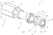
- Fig. 3 shows an exploded view of the rotor 1 from Fig. 1 ,
- the rotor magnet 2 has on the side facing the sensor magnet two positive locking lugs 20 which form the previously described form-fit 11 with the form-fitting grooves 21 of the spacer 9.
- the lugs 20 and grooves 21 are referred to herein generally as form-fitting contours and in other embodiments may have different but mutually complementary shapes to form the fit 11.
- the filling element 4 is shown in its cured form outside the rotor magnet 2 and the sensor magnet 3, wherein the filling element 4 forms a negative mold of parts of all components of the rotor 1.
- the visible to the outside surfaces are formed by appropriate tools (not shown), for example, if at least the rotor magnet 2 and the sensor magnet 3 are aligned and arranged to each other and are connected in the tool with a filling element forming and injectable material.
- the spacer 9 is ring-shaped or hollow cylindrical. Furthermore, the spacer 9 in addition to the aforementioned form-fitting grooves 21 (only one is visible) on three arcuate outer panels 26 which are arranged equidistant or at the same angle to each other on the outer circumference of the spacer 9. Since the outer panels 26 extend over a bearing surface of the spacer 9 for the magnetic element 8, these apertures 26 serve as boundaries for the magnetic element eighth
- Another function of the outer panels 26 is to form a plurality of channels for the material to be injected for the filling element 4. As a result, as can be seen in the case of the hardened filling element 4, corresponding recesses or “windows” can form, in which the outer panels 26 are arranged and prevent the spacer 9 from detaching from the rotor magnet 2.
- two positive locking lugs 23 are formed on the bearing surface of the spacer 9 at the inner edge, which form with the two positive locking grooves 24 of the magnetic element 8 each form-fitting (not shown) for a torsion and predetermined arrangement of the spacer 9 with the magnetic element 8.
- these form-locks have the same function as the form-fit 11 (not shown) that can be formed by the lugs 20 and grooves 21.
- the magnetic element 8 has a sensor track with alternating magnetically polarized sections 18 and 19. It is also possible that the magnetic element 8 has a plurality of sensor tracks in order to better measure the position and the speed of the rotor 1.
- Fig. 4 shows a cross section through another rotor 1 according to a second embodiment of the present invention. Except for the rotor magnet 2, all components of the rotor 1 are identical to those of the rotor Fig. 1 to 3 ,
- the rotor magnet 2 is additionally formed with a vertical hole-shaped depression, which allows a sensor magnet 3 inserted in the rotor magnet 2, that the axially aligned side of the rotor magnet 2 and the surface of the sensor magnet 3, in particular that of the magnetic element 8, aligned perpendicular to the shaft axis 7 Form level. This leads to a more compact design of the rotor 1.
- Fig. 5 shows a perspective view of the rotor Fig. 4 , The components of the filling element 4 that are formed around and in the magnetic element 8 are easily recognizable.
- Fig. 6 shows an exploded view of the rotor Fig. 4 , Here, the recess formed on one side of the rotor magnet 2 is shown.
- the corresponding positive locking lugs 20 are axially offset in the interior of the rotor magnet 2 and thus no longer visible in this view.
- Fig. 7 shows a cross section through another rotor 1 according to a third embodiment of the present invention. Except for the sensor magnet 3, all components of the rotor 1 are identical to those of the rotor Fig. 1 , As a special feature, the sensor magnet 3 is no longer in two pieces (from spacer 9 and magnetic element 8), but integrally formed. Therefore, no longer known in the first and second embodiments, outer panels 26 are necessary to prevent the spacer 9 from detaching. Instead, only the inner half rings 25 are formed to prevent the sensor magnet 3 by means of the filling element 4 at a detachment and thus to attach this to the rotor magnet 2.
- Fig. 8 shows an exploded view of the rotor 1 from Fig. 7 , wherein the one-piece sensor magnet 3 to one in relation to in Fig. 3 and 6 shown different negative shape of the filling element 4 leads.
Landscapes
- Engineering & Computer Science (AREA)
- Power Engineering (AREA)
- Microelectronics & Electronic Packaging (AREA)
Applications Claiming Priority (1)
| Application Number | Priority Date | Filing Date | Title |
|---|---|---|---|
| DE102017111797.0A DE102017111797B4 (de) | 2017-05-30 | 2017-05-30 | Rotor mit Sensormagnet sowie dessen Herstellungsverfahren |
Publications (1)
| Publication Number | Publication Date |
|---|---|
| EP3410585A1 true EP3410585A1 (fr) | 2018-12-05 |
Family
ID=62104169
Family Applications (1)
| Application Number | Title | Priority Date | Filing Date |
|---|---|---|---|
| EP18170310.9A Withdrawn EP3410585A1 (fr) | 2017-05-30 | 2018-05-02 | Rotor à aimant de détection ainsi que son procédé de fabrication |
Country Status (2)
| Country | Link |
|---|---|
| EP (1) | EP3410585A1 (fr) |
| DE (1) | DE102017111797B4 (fr) |
Cited By (4)
| Publication number | Priority date | Publication date | Assignee | Title |
|---|---|---|---|---|
| WO2024208525A1 (fr) * | 2023-04-06 | 2024-10-10 | Valeo Embrayages | Rotor pour moteur électrique |
| WO2025113348A1 (fr) * | 2023-11-29 | 2025-06-05 | 延锋国际汽车技术有限公司 | Ensemble rotor, procédé de fabrication d'ensemble rotor et moteur |
| EP4625778A1 (fr) * | 2024-03-29 | 2025-10-01 | BYD Company Limited | Arbre de noyau de stator, moteur linéaire, suspension électromagnétique et véhicule |
| EP4629481A1 (fr) * | 2024-03-29 | 2025-10-08 | BYD Company Limited | Ensemble stator, moteur linéaire, système de suspension et véhicule |
Citations (4)
| Publication number | Priority date | Publication date | Assignee | Title |
|---|---|---|---|---|
| US5053664A (en) * | 1989-01-18 | 1991-10-01 | Aisan Kogyo Kabushiki Kaisha | Motor-driven fuel pump |
| JP2009284658A (ja) * | 2008-05-22 | 2009-12-03 | Asmo Co Ltd | ロータ及びモータ |
| US20150084446A1 (en) * | 2013-09-24 | 2015-03-26 | Electro-Motor Dynamics, LLC | Direct drive stacked motor acuator |
| WO2015080077A1 (fr) * | 2013-11-27 | 2015-06-04 | 三菱電機株式会社 | Rotor de moteur électrique, moteur électrique et conditionneur d'air |
Family Cites Families (2)
| Publication number | Priority date | Publication date | Assignee | Title |
|---|---|---|---|---|
| DE102015002562B4 (de) | 2015-02-27 | 2019-02-14 | Brose Fahrzeugteile GmbH & Co. Kommanditgesellschaft, Würzburg | Elektrische Maschine |
| DE102015115153A1 (de) | 2015-09-09 | 2017-03-09 | Minebea Co., Ltd. | Bürstenloser Gleichstrommotor mit integrierter elektronischer Schaltung |
-
2017
- 2017-05-30 DE DE102017111797.0A patent/DE102017111797B4/de not_active Expired - Fee Related
-
2018
- 2018-05-02 EP EP18170310.9A patent/EP3410585A1/fr not_active Withdrawn
Patent Citations (4)
| Publication number | Priority date | Publication date | Assignee | Title |
|---|---|---|---|---|
| US5053664A (en) * | 1989-01-18 | 1991-10-01 | Aisan Kogyo Kabushiki Kaisha | Motor-driven fuel pump |
| JP2009284658A (ja) * | 2008-05-22 | 2009-12-03 | Asmo Co Ltd | ロータ及びモータ |
| US20150084446A1 (en) * | 2013-09-24 | 2015-03-26 | Electro-Motor Dynamics, LLC | Direct drive stacked motor acuator |
| WO2015080077A1 (fr) * | 2013-11-27 | 2015-06-04 | 三菱電機株式会社 | Rotor de moteur électrique, moteur électrique et conditionneur d'air |
Cited By (4)
| Publication number | Priority date | Publication date | Assignee | Title |
|---|---|---|---|---|
| WO2024208525A1 (fr) * | 2023-04-06 | 2024-10-10 | Valeo Embrayages | Rotor pour moteur électrique |
| WO2025113348A1 (fr) * | 2023-11-29 | 2025-06-05 | 延锋国际汽车技术有限公司 | Ensemble rotor, procédé de fabrication d'ensemble rotor et moteur |
| EP4625778A1 (fr) * | 2024-03-29 | 2025-10-01 | BYD Company Limited | Arbre de noyau de stator, moteur linéaire, suspension électromagnétique et véhicule |
| EP4629481A1 (fr) * | 2024-03-29 | 2025-10-08 | BYD Company Limited | Ensemble stator, moteur linéaire, système de suspension et véhicule |
Also Published As
| Publication number | Publication date |
|---|---|
| DE102017111797A1 (de) | 2018-12-06 |
| DE102017111797B4 (de) | 2021-11-04 |
Similar Documents
| Publication | Publication Date | Title |
|---|---|---|
| DE102015121102B4 (de) | Rotorvorrichtung für einen Elektromotor und/oder Generator, Rotor und Motor mit einer solchen Rotorvorrichtung sowie Herstellungsverfahren | |
| EP3683551B1 (fr) | Unité de balayage pour un dispositif de mesure d'angle | |
| DE112017000172T5 (de) | Bürstenloser Gleichstrommotor | |
| DE102008032844A1 (de) | Permanentmagnetischer Rotor | |
| WO2007033857A1 (fr) | Module de dent pour partie primaire d'une machine electrique excitee par des aimants permanents | |
| EP3410585A1 (fr) | Rotor à aimant de détection ainsi que son procédé de fabrication | |
| EP1397691A1 (fr) | Dispositif permettant de generer un signal dependant de la vitesse de rotation pour un moteur electrique, en particulier pour un moteur a courant continu a commutation electronique | |
| DE4033454A1 (de) | Permanentmagnetrotor | |
| DE102008042912A1 (de) | Sensoreinrichtung zum Erfassen der Drehlage eines rotierenden Bauteils | |
| DE102011052131A1 (de) | Reluktanzmotor und verfahren zu dessen montage | |
| EP2019471A2 (fr) | Machine à flux transversal | |
| EP3352337A1 (fr) | Rotor d'une machine tournante électrique à excitation permanente et procédé de production d'un tel rotor | |
| DE2425135A1 (de) | 6-poliger permanentmagnetischer elektromotor | |
| EP3683552B1 (fr) | Unité de balayage pour un dispositif de mesure d'angle | |
| EP3093960A1 (fr) | Rotor doté d'un aimant en anneau et d'une partie en matière plastique | |
| DE102018215783A1 (de) | Positionserfassungssystem und Verfahren zur Erfassung einer Bewegung einer Maschine | |
| DE2215673A1 (de) | Mechanisch-elektrischer wandler | |
| DE102018213400A1 (de) | Sensorsystem zur Bestimmung mindestens einer Rotationseigenschaft eines um mindestens eine Rotationsachse rotierenden Elements und Verfahren zur Herstellung | |
| DE102017111798B4 (de) | Rotor mit Sensormagnet sowie dessen Herstellungsverfahren | |
| EP4220095B1 (fr) | Capteur de rotation doté d'un générateur pour l'alimentation autonome en énergie | |
| EP2909921A2 (fr) | Ensemble stator pour une machine électrique à excitation par aimants permanents | |
| DE102015201493A1 (de) | Magnetfelderzeugende Komponente für eine elektrische Maschine | |
| DE3924842C1 (fr) | ||
| WO2017125273A1 (fr) | Moteur électrique à capteur angulaire inductif | |
| DE102024105194A1 (de) | Kunststoffgebundener gespritzter Permanentmagnet |
Legal Events
| Date | Code | Title | Description |
|---|---|---|---|
| PUAI | Public reference made under article 153(3) epc to a published international application that has entered the european phase |
Free format text: ORIGINAL CODE: 0009012 |
|
| AK | Designated contracting states |
Kind code of ref document: A1 Designated state(s): AL AT BE BG CH CY CZ DE DK EE ES FI FR GB GR HR HU IE IS IT LI LT LU LV MC MK MT NL NO PL PT RO RS SE SI SK SM TR |
|
| AX | Request for extension of the european patent |
Extension state: BA ME |
|
| 17P | Request for examination filed |
Effective date: 20190513 |
|
| GRAP | Despatch of communication of intention to grant a patent |
Free format text: ORIGINAL CODE: EPIDOSNIGR1 |
|
| INTG | Intention to grant announced |
Effective date: 20190909 |
|
| STAA | Information on the status of an ep patent application or granted ep patent |
Free format text: STATUS: THE APPLICATION IS DEEMED TO BE WITHDRAWN |
|
| 18D | Application deemed to be withdrawn |
Effective date: 20200121 |