EP3410712A1 - Appareils de codage et de décodage d'images, procédés de codage et de décodage d'images, programmes associés et supports d'enregistrement enregistrés avec les programmes - Google Patents
Appareils de codage et de décodage d'images, procédés de codage et de décodage d'images, programmes associés et supports d'enregistrement enregistrés avec les programmes Download PDFInfo
- Publication number
- EP3410712A1 EP3410712A1 EP18184537.1A EP18184537A EP3410712A1 EP 3410712 A1 EP3410712 A1 EP 3410712A1 EP 18184537 A EP18184537 A EP 18184537A EP 3410712 A1 EP3410712 A1 EP 3410712A1
- Authority
- EP
- European Patent Office
- Prior art keywords
- gradient
- image
- prediction
- encoded
- encoding
- Prior art date
- Legal status (The legal status is an assumption and is not a legal conclusion. Google has not performed a legal analysis and makes no representation as to the accuracy of the status listed.)
- Ceased
Links
Images










Classifications
-
- H—ELECTRICITY
- H04—ELECTRIC COMMUNICATION TECHNIQUE
- H04N—PICTORIAL COMMUNICATION, e.g. TELEVISION
- H04N19/00—Methods or arrangements for coding, decoding, compressing or decompressing digital video signals
- H04N19/10—Methods or arrangements for coding, decoding, compressing or decompressing digital video signals using adaptive coding
- H04N19/189—Methods or arrangements for coding, decoding, compressing or decompressing digital video signals using adaptive coding characterised by the adaptation method, adaptation tool or adaptation type used for the adaptive coding
- H04N19/19—Methods or arrangements for coding, decoding, compressing or decompressing digital video signals using adaptive coding characterised by the adaptation method, adaptation tool or adaptation type used for the adaptive coding using optimisation based on Lagrange multipliers
-
- H—ELECTRICITY
- H04—ELECTRIC COMMUNICATION TECHNIQUE
- H04N—PICTORIAL COMMUNICATION, e.g. TELEVISION
- H04N19/00—Methods or arrangements for coding, decoding, compressing or decompressing digital video signals
- H04N19/10—Methods or arrangements for coding, decoding, compressing or decompressing digital video signals using adaptive coding
- H04N19/102—Methods or arrangements for coding, decoding, compressing or decompressing digital video signals using adaptive coding characterised by the element, parameter or selection affected or controlled by the adaptive coding
- H04N19/103—Selection of coding mode or of prediction mode
- H04N19/11—Selection of coding mode or of prediction mode among a plurality of spatial predictive coding modes
-
- H—ELECTRICITY
- H04—ELECTRIC COMMUNICATION TECHNIQUE
- H04N—PICTORIAL COMMUNICATION, e.g. TELEVISION
- H04N19/00—Methods or arrangements for coding, decoding, compressing or decompressing digital video signals
- H04N19/10—Methods or arrangements for coding, decoding, compressing or decompressing digital video signals using adaptive coding
- H04N19/134—Methods or arrangements for coding, decoding, compressing or decompressing digital video signals using adaptive coding characterised by the element, parameter or criterion affecting or controlling the adaptive coding
- H04N19/136—Incoming video signal characteristics or properties
-
- H—ELECTRICITY
- H04—ELECTRIC COMMUNICATION TECHNIQUE
- H04N—PICTORIAL COMMUNICATION, e.g. TELEVISION
- H04N19/00—Methods or arrangements for coding, decoding, compressing or decompressing digital video signals
- H04N19/10—Methods or arrangements for coding, decoding, compressing or decompressing digital video signals using adaptive coding
- H04N19/134—Methods or arrangements for coding, decoding, compressing or decompressing digital video signals using adaptive coding characterised by the element, parameter or criterion affecting or controlling the adaptive coding
- H04N19/146—Data rate or code amount at the encoder output
- H04N19/147—Data rate or code amount at the encoder output according to rate distortion criteria
-
- H—ELECTRICITY
- H04—ELECTRIC COMMUNICATION TECHNIQUE
- H04N—PICTORIAL COMMUNICATION, e.g. TELEVISION
- H04N19/00—Methods or arrangements for coding, decoding, compressing or decompressing digital video signals
- H04N19/10—Methods or arrangements for coding, decoding, compressing or decompressing digital video signals using adaptive coding
- H04N19/169—Methods or arrangements for coding, decoding, compressing or decompressing digital video signals using adaptive coding characterised by the coding unit, i.e. the structural portion or semantic portion of the video signal being the object or the subject of the adaptive coding
- H04N19/182—Methods or arrangements for coding, decoding, compressing or decompressing digital video signals using adaptive coding characterised by the coding unit, i.e. the structural portion or semantic portion of the video signal being the object or the subject of the adaptive coding the unit being a pixel
-
- H—ELECTRICITY
- H04—ELECTRIC COMMUNICATION TECHNIQUE
- H04N—PICTORIAL COMMUNICATION, e.g. TELEVISION
- H04N19/00—Methods or arrangements for coding, decoding, compressing or decompressing digital video signals
- H04N19/46—Embedding additional information in the video signal during the compression process
-
- H—ELECTRICITY
- H04—ELECTRIC COMMUNICATION TECHNIQUE
- H04N—PICTORIAL COMMUNICATION, e.g. TELEVISION
- H04N19/00—Methods or arrangements for coding, decoding, compressing or decompressing digital video signals
- H04N19/50—Methods or arrangements for coding, decoding, compressing or decompressing digital video signals using predictive coding
- H04N19/593—Methods or arrangements for coding, decoding, compressing or decompressing digital video signals using predictive coding involving spatial prediction techniques
-
- H—ELECTRICITY
- H04—ELECTRIC COMMUNICATION TECHNIQUE
- H04N—PICTORIAL COMMUNICATION, e.g. TELEVISION
- H04N19/00—Methods or arrangements for coding, decoding, compressing or decompressing digital video signals
- H04N19/60—Methods or arrangements for coding, decoding, compressing or decompressing digital video signals using transform coding
- H04N19/61—Methods or arrangements for coding, decoding, compressing or decompressing digital video signals using transform coding in combination with predictive coding
Definitions
- the present invention relates to an image encoding apparatus and a method for encoding an image using intraframe prediction, an image decoding apparatus and a method for decoding encoded data encoded by the image encoding technique, an image encoding program for use in realizing the image encoding apparatus and a computer readable recording medium recorded with the program, and an image decoding program for use in realizing the image decoding apparatus and a computer readable recording medium recorded with the program.
- intraframe prediction encoding that performs a prediction within the same frame can hardly achieve compression efficiency as high as that achieved by interframe prediction encoding that performs a prediction between different frames, there is a demand for an intraframe prediction encoding scheme with high compression efficiency. Moreover, there is a possibility that the improvement of compression efficiency obtained by the intraframe encoding contributes to the improvement of compression efficiency of interframe encoding that refers to the image, and thus in view of this, the improvement of compression efficiency of an intraframe prediction encoding scheme is expected.
- the intraframe prediction which performs a prediction within the same frame in spatial dimensions, has been adopted since video encoding standard H.264/MPEG-4AVC (e.g. refer to pp. 106 of non-patent document 1).
- the intraframe prediction is performed on a block by block basis, and in H.264/MPEG-4AVC, three kinds of block sizes (4 ⁇ 4, 8 ⁇ 8, and 16 ⁇ 16) can be used with respect to a luminance signal. Moreover, in the respective block sizes, a plurality of prediction modes can be selected. In the case of a 4 ⁇ 4 and 8 ⁇ 8 block size, 9 kinds of prediction modes have been prepared, and in the case of a 16 ⁇ 16 block size, 4 kinds of prediction modes have been prepared.
- a chrominance signal With respect to a chrominance signal, only the 8 ⁇ 8 block size can be used, and its prediction direction is the same as that in the luminance signal of a 16 ⁇ 16 block. However, the relationship between prediction mode numbers and prediction directions is different therefrom (e.g. refer to pp. 106-112 of non-patent document 1 and pp. 116-135 of non-patent document 2).
- pixels generated through the intraframe prediction are obtained by copying the same values as those of pixels which are positioned on a block neighboring a block to be encoded and which are nearest to the block to be encoded, without changing the values of the pixels.
- FIG. 36 illustrates the case in which a block to be encoded is a 4 ⁇ 4 block of a luminance signal and its prediction mode is a vertical prediction (a prediction mode 0).
- a prediction mode 0 a vertical prediction
- a prediction mode 0 is a prediction in the vertical direction
- the value (e.g. 73) of the pixel A is copied into four successive pixels which are positioned below the pixel A.
- the value (e.g. 79) of the pixel B, the value (e.g. 86) of the pixel C, and the value (e.g. 89) of the pixel D are copied into four successive pixels which are positioned below the pixels B, C, and D, respectively.
- pixels generated through the intraframe prediction are obtained by copying the same values as those of pixels which are positioned on a block neighboring a block to be encoded and which are nearest to the block to be encoded, without changing the values of the pixels.
- the prediction can be performed by assigning a value of 128 or the value of a neighboring pixel. For example, in a block including the uppermost row of a frame, nine pixels from X to H cannot always be referred to, and thus the value of 128 is used. Moreover, if upper left and upper blocks exist, but an upper right block does not exist, predicted pixels are generated by assigning the value of the pixel D to the pixels E, F, G, and H.
- a conventional intraframe prediction copies a reference pixel as it is without changing its pixel value.
- the conventional intraframe prediction has no problem.
- the original signal has the property of sequentially changing its value along the prediction direction.
- the present invention has been made in consideration of the above-described circumstances, and an object thereof is to provide a novel image encoding technique that can improve compression efficiency when an image that includes great gradation by intraframe prediction is encoded.
- the present invention provides an image encoding apparatus for encoding an image using an intraframe prediction which includes (i) a selection means for selecting a gradient of a pixel value that is indicated by an image signal to be predicted among a plurality of gradient candidates; (ii) a generation means for generating a predicted signal with a gradient applied thereto in accordance with the distance from a prediction reference pixel based on the gradient selected by the selection means; (iii) an intraframe encoding means for intraframe-encoding the image signal to be predicted based on the predicted signal generated by the generation means; and (iv) a gradient information encoding means for encoding information indicating the size of the gradient (i.e. information about the size itself, information such as an index that makes it possible to identify the size) selected by the selection means.
- the above-described processing means may even be realized by a computer program.
- the computer program may be provided as being recorded in a proper computer readable recording medium or may be provided through a network.
- the computer program may be installed when the present invention is realized and may operate on control means such as a CPU, thereby realizing the present invention.
- the present invention provides an image decoding apparatus for decoding encoded data of an image encoded using an intraframe prediction which includes (i) an acquisition means for acquiring gradient information used on an image encoding side by decoding information for applying a gradient of a pixel value to a predicted signal in accordance with the distance from a prediction reference pixel; (ii) a restoration means for restoring the predicted signal generated on the image encoding side based on the gradient acquired by the acquisition means; and (iii) a generation means for decoding a residual signal encoded on the image encoding side, and generating a decoded image signal based on the decoded residual signal and the predicted signal restored by the restoration means.
- the above-described processing means may be realized even by a computer program.
- the computer program may be provided as being recorded in a proper computer readable recording medium or may be provided through a network.
- the computer program may be installed when the present invention is realized and may operate on control means such as a CPU, thereby realizing the present invention.
- the image encoding apparatus for example, generates a plurality of predicted signal candidates having different gradients based on the plurality of gradient candidates, and selects the gradient indicated by the image signal to be predicted among the plurality of gradient candidates by identifying the predicted signal candidate having the minimum encoding cost among the predicted signal candidates.
- the image encoding apparatus generates the predicted signal with the gradient applied thereto in accordance with the distance from the prediction reference pixel based on the selected gradient, and performs intraframe-encoding of the image signal to be predicted based on the generated predicted signal. Then, the image encoding apparatus encodes information indicating the size of the selected gradient to inform the image decoding apparatus of the size of the selected gradient.
- the image decoding apparatus which has received the encoded data generated by the image encoding apparatus, acquires information about the gradient used on the image encoding side by decoding the information indicating the size of the encoded gradient. Then, the image decoding apparatus restores the predicted signal generated on the image encoding side based on the acquired gradient, decodes the residual signal encoded on the image encoding side, and generates the decoded image signal based on the decoded residual signal and the restored predicted signal.
- the present invention provides an image encoding apparatus for encoding an image using an intraframe prediction which includes (i) an estimation means for estimating a gradient of a pixel value that is indicated by an image signal to be predicted based on an image signal which has already been encoded; (ii) a generation means for generating a predicted signal with a gradient applied thereto in accordance with the distance from a prediction reference pixel based on the gradient estimated by the estimation means; and (iii) an intraframe-encoding means for intra frame-encoding the image signal to be predicted based on the predicted signal generated by the generation means.
- the above-described processing means may be realized even by a computer program.
- the computer program may be provided as being recorded in a proper computer readable recording medium or may be provided through a network.
- the computer program may be installed when the present invention is realized and may operate on control means such as a CPU, thereby realizing the present invention.
- the present invention provides an image decoding apparatus for decoding encoded data of an image encoded using an intraframe prediction which includes (i) an estimation means for estimating a gradient of a pixel value that is indicated by an image signal to be predicted based on an image signal which has already been decoded; (ii) a predicted signal generation means for generating a predicted signal with a gradient applied thereto in accordance with the distance from a prediction reference pixel based on the gradient estimated by the estimation means; and (iii) a decoded image signal means for decoding a residual signal encoded on an image encoding side, and generating a decoded image signal based on the decoded residual signal and the predicted signal generated by the predicted signal generation means.
- the above-described processing means may be realized even by a computer program.
- the computer program may be provided as being recorded in a proper computer readable recording medium or may be provided through a network.
- the computer program may be installed when the present invention is realized and may operate on control means such as a CPU, thereby realizing the present invention.
- the image encoding apparatus estimates the gradient indicated by the image signal to be predicted based on the image signal which has already been encoded. Then, the image encoding apparatus generates the predicted signal with the gradient applied thereto in accordance with the distance from the prediction reference pixel based on the estimated gradient, and performs intraframe-encoding of the image signal to be predicted based on the generated predicted signal.
- the image decoding apparatus which has received the encoded data generated by the image encoding apparatus, estimates the gradient indicated by the image signal to be predicted based on the image signal which has already been decoded. Then, the image decoding apparatus generates the predicted signal with the gradient applied thereto in accordance with the distance from the prediction reference pixel based on the estimated gradient. Then, the image decoding apparatus decodes the residual signal encoded on the encoding side, and generates the decoded image signal based on the decoded residual signal and the generated predicted signal.
- the image encoding apparatus and the image decoding apparatus estimate the gradient in accordance with the same algorithm, it is not required for the image encoding apparatus to inform the image decoding apparatus of the size of the estimated gradient. Accordingly, the amount of the encoded data generated by the image encoding apparatus becomes small to that extent, but the image decoding apparatus should execute an operation for estimating the gradient.
- the image encoding apparatus may be provided with a gradient information encoding means (which can be also realized by a computer program) for encoding information that indicates the size of the estimated gradient.
- a gradient information encoding means (which can be also realized by a computer program) for encoding information that indicates the size of the estimated gradient.
- the image decoding apparatus decodes the encoded data generated by the image encoding apparatus.
- the second aspect of the present invention does not consider the signal value per se of the reference pixel as the predicted signal, but it applies the gradient thereto, thereby realizing the intraframe prediction with a smaller prediction error. That is, by applying the gradient to the value of the reference pixel, it is possible to generate pixels that can provide a further reduced prediction error, and as a result, an efficient intraframe prediction, which is an object of the present invention, can be realized.
- the present invention provides an image encoding apparatus which includes (i) means for selecting a gradient applied to an image signal to be predicted among a plurality of gradient candidates that indicate a value added to a pixel value; (ii) means for generating a predicted signal to which the selected gradient is applied; (iii) means for intraframe-encoding the image signal to be predicted based on the generated predicted signal; and (iv) means for encoding information that indicates the size of the selected gradient.
- the present invention provides an image encoding apparatus which includes (i) means for estimating a gradient that indicates a value added to a pixel value of an image signal to be predicted based on an image signal which has already been encoded; (ii) means for generating a predicted signal to which the estimated gradient is applied; and (iii) means for intraframe-encoding the image signal to be predicted based on the generated predicted signal.
- the basic operation of selecting or estimating the gradient and generating a predicted signal based on the gradient is common with the first and second aspects.
- the present invention provides the following image decoding apparatuses corresponding to the image encoding apparatuses that deal with the DC prediction:
- the present invention it is possible to execute an efficient intraframe prediction with respect to an image including a gradation that may cause prediction errors to increase and thus cause the deterioration of the encoding efficiency in the conventional intraframe prediction, and thus it is possible to improve compression efficiency.
- the signal value per se of a reference pixel is not considered as a predicted signal, but a gradient is applied thereto to thereby realize intraframe prediction with a smaller prediction error.
- a block to be encoded includes a gradation.
- the present invention generates a predicted signal similar to the original signal by applying a constant gradient to the predicted signal, thereby the residual signal can be decreased, and the efficiency improvements in the intraframe prediction can be realized.
- the present invention can generate pixels so that a prediction error can be further reduced, and as a result, an efficient intraframe prediction, which is an object of the present invention, can be realized.
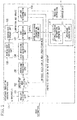
- FIG. 2 illustrates an intraframe prediction encoding apparatus 10 according to an embodiment of the present invention.
- An intraframe prediction encoding apparatus 10 encodes an image to be processed, which may be a still image or an image to be subjected to intraframe encoding included in video, using an intraframe prediction.
- the intraframe prediction encoding apparatus 10 includes a gradient selection unit 101, a prediction mode selection unit 102, an intraframe prediction unit 103, a rate distortion cost calculation unit 104, a minimum cost storage unit 105, a minimum cost initialization unit 106, a cost determination unit 107, an optimum encoding information storage unit 108, a loop end determination unit 109, an optimum encoding information encoding unit 110, and an intraframe encoding unit 111.
- the gradient selection unit 101 selects a gradient to be applied to a predicted signal (exactly speaking, a candidate of such a gradient when the gradient selection unit 101 performs selection).
- the prediction mode selection unit 102 selects a prediction mode for the intraframe prediction.
- the intraframe prediction unit 103 generates a predicted signal with a gradient used in the intraframe prediction applied thereto based on the gradient selected by the gradient selection unit 101 and the prediction mode selected by the prediction mode selection unit 102.
- the rate distortion cost calculation unit 104 calculates a rate distortion cost that is an encoding cost based on the predicted signal generated by the intraframe prediction unit 103.
- the minimum cost storage unit 105 stores the minimum value of the rate distortion cost calculated by the rate distortion cost calculation unit 104.
- the minimum cost initialization unit 106 When the intraframe prediction encoding starts, the minimum cost initialization unit 106 writes an initial value of the rate distortion cost that indicates a large value into the minimum cost storage unit 105.
- the cost determination unit 107 compares the rate distortion cost calculated by the rate distortion cost calculation unit 104 with the rate distortion cost stored in the minimum cost storage unit 105, and if the rate distortion cost calculated by the rate distortion cost calculation unit 104 is smaller, the cost determination unit 107 updates the rate distortion cost stored in the minimum cost storage unit 105 using the rate distortion cost calculated by the rate distortion cost calculation unit 104, and further updates information on the gradient and the prediction mode stored in the optimum encoding information storage unit 108 in accordance with the gradient and the prediction mode at that time.
- the optimum encoding information storage unit 108 stores information on the optimum gradient and the prediction mode, which will be updated by the cost determination unit 107.
- the loop end determination unit 109 instructs the gradient selection unit 101 to select the next gradient, and simultaneously instructs the prediction mode selection unit 102 to select the next prediction mode. Accordingly, the loop end determination unit 109 performs control so that all the combinations of gradients and prediction modes are selected, and if all the combinations of the gradients and the prediction modes have been selected, the loop end determination unit 109 instructs the optimum encoding information encoding unit 110 and the intraframe encoding unit 111 to perform the encoding.
- the optimum encoding information encoding unit 110 Upon receipt of an encoding instruction from the loop end determination unit 109, the optimum encoding information encoding unit 110 reads the information on the gradient and the prediction mode from the optimum encoding information storage unit 108, and encodes the information.
- the intraframe encoding unit 111 Upon receipt of an encoding instruction from the loop end determination unit 109, the intraframe encoding unit 111 reads the information on the gradient and the prediction mode from the optimum encoding information storage unit 108, generates a predicted signal to which a gradient is applied in accordance with the read gradient and prediction mode, and encodes a residual signal between the image signal of the block to be encoded and the generated predicted signal.
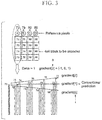
- the intraframe prediction that is executed by the intraframe prediction encoding apparatus 10 according to the present embodiment will be described in accordance with FIG. 3 .
- the block to be encoded is a 4 ⁇ 4 block.
- the size that is a reference of the gradient is defined as a gradient constant ⁇
- the range that can be taken by the gradient is defined as a gradient adjustment coefficient gradient[n].
- ⁇ is a constant
- n is an integer which indicates the number of (kinds of) gradients that can be taken.
- gradient[0], gradient[1], and gradient[2] may be set to any values, they are set to -1, 0, and 1 in the example shown in FIG. 3 .
- the gradient ⁇ is applied to the distance from the reference pixel to the predicted pixel.
- the intraframe prediction encoding apparatus 10 that is configured as shown in FIG. 2 generates a predicted signal in accordance with Equation (1).
- FIG. 4 illustrates a flowchart executed by the intraframe prediction encoding apparatus 10 according to the present embodiment. The operation executed by the intraframe prediction encoding apparatus 10 will now be described in accordance with the flowchart.
- the intraframe prediction encoding apparatus 10 initializes the minimum value J min of a rate distortion cost J i,j , which is to be used in step S107 described later, to MAXcost that indicates a sufficiently large value (i.e. a value which has no possibility that the rate distortion cost J i,j actually takes).
- step S102 the value of the gradient constant ⁇ is initialized into a predetermined value.
- step S103 a loop 1 (where, variable is i) that designates the size of the gradient is started. That is, the loop 1 is an n-times loop that corresponds to the number of the kinds of gradients. At the first round, zero is assigned to i as an initial value.
- step S104 the gradient ⁇ is calculated from ⁇ and gradient[i], and then it is preserved.
- step S105 a loop 2 (where, variable is j) that designates a prediction mode taken by the block to be encoded is started.
- the prediction modes that can be taken by the block to be encoded vary depending on its position in an image, and thus ⁇ is defined as a set of all prediction modes that can be taken by the block to be encoded.
- ⁇ (here, ⁇ is the smallest prediction mode number among the modes that can be taken) is assigned to j.
- step S106 a predicted signal to which a gradient is applied is generated in accordance with Equation (1) using the gradient ⁇ obtained in step S104.
- step S107 the rate distortion cost J i,j is obtained.
- SSD is the sum of the squares of the absolute values of prediction errors
- ⁇ is a Lagrange multiplier for prediction mode determination
- R block is a code amount generated when the block to be encoded is encoded in a selected prediction mode j
- R gradient is a code amount generated when gradient information i is encoded.
- step S108 by deciding whether or not Equation (3) is satisfied, it is determined whether or not the cost J i,j calculated in step S107 is the minimum. J i , j ⁇ J min
- step S107 If it is decided that the cost J i,j calculated in step S107 is below the minimum cost J min according to the decision in step S108, the processing proceeds to step S109, the gradient information i and the value of the prediction mode j at that time are recorded, and J min is updated as in the following Equations (4) to (6).
- J min J i , j
- step S109 is not performed, and the update process indicated by Equations (4) to (6) is not performed.
- the above-described cost calculation process is performed in a manner in which the loop 2 is repeated in the range of j ⁇ (i.e. with respect to all prediction modes that can be taken), and when the loop 2 is ended, the next gradient[i] is selected, and the loop 1 is repeated in the range of 0 ⁇ i ⁇ n.
- step S110 information on the obtained best_gradient and best_mode is encoded.
- a generally used method such as arithmetic coding, may be used as the encoding scheme.
- the encoding information is inserted into a header and so on.
- step S111 a predicted signal to which a gradient is applied is generated using the obtained best_gradient and best_mode, and the block to be encoded is encoded.
- the concept of the present invention can be applied to sizes which are different from the size of the 4 ⁇ 4 block.
- the present invention can be applied to not only the luminance signal but also the chrominance signal in the same manner.
- FIG. 5 illustrates an intraframe prediction decoding apparatus 20 according to an embodiment of the present invention which decodes encoded data generated by the intraframe prediction encoding apparatus 10 configured as shown in FIG. 2 .
- the intraframe prediction decoding apparatus 20 includes a gradient/prediction mode decoding unit 201, a predicted signal restoration unit 202, a residual signal decoding unit 203, and a decoded image generation unit 204.
- the gradient/prediction mode decoding unit 201 decodes information on the gradient and the prediction mode that is inserted into the header and so on of the encoded data.
- the predicted signal restoration unit 202 restores the predicted signal to which the gradient is applied that is generated by the intraframe prediction encoding apparatus 10 based on the gradient and the prediction mode decoded by the gradient/prediction mode decoding unit 201.
- the residual signal decoding unit 203 decodes the residual signal encoded by the intraframe prediction encoding apparatus 10 from the encoded data.
- the decoded image generation unit 204 generates the decoded image signal based on the predicted signal restored by the predicted signal restoration unit 202 and the residual signal decoded by the residual signal decoding unit 203.
- FIG. 6 illustrates a flowchart executed by the intraframe prediction decoding apparatus 20 according to the present embodiment. Next, the process executed by the intraframe prediction decoding apparatus 20 will be described in accordance with the flowchart.
- the intraframe prediction decoding apparatus 20 upon input of the encoded data generated by the intraframe prediction encoding apparatus 10, in the first place, in step S201, the intraframe prediction decoding apparatus 20 according to the present embodiment decodes information of the best_gradient and best_mode inserted into the header and so on of the input encoded data.
- step S202 the intraframe prediction decoding apparatus 20 restores the predicted signal to which the gradient is applied that is generated by the intraframe prediction encoding apparatus 10 in accordance with the decoded best_gradient and best_mode.
- step S203 the intraframe prediction decoding apparatus 20 decodes the residual signal (i.e. the difference value between the (original) image signal and the predicted signal) encoded by the intraframe prediction encoding apparatus 10 from the input encoded data.
- the residual signal i.e. the difference value between the (original) image signal and the predicted signal
- step S204 the intraframe prediction decoding apparatus 20 generates the decoded image signal based on the restored predicted signal to which the gradient is applied and the decoded residual signal.
- the intraframe prediction decoding apparatus 20 configured as shown in FIG. 5 decodes the encoded data generated by the intraframe prediction encoding apparatus 10 configured as shown in FIG. 2 .
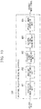
- FIG. 7 illustrates an intraframe prediction encoding apparatus 100 as another embodiment of the present invention.
- the intraframe prediction encoding apparatus 100 includes a prediction mode selection unit 301, a gradient calculation unit 302, an intraframe prediction unit 303, a rate distortion cost calculation unit 304, a minimum cost storage unit 305, a minimum cost initialization unit 306, a cost determination unit 307, an optimum encoding information storage unit 308, a loop end determination unit 309, an optimum prediction mode encoding unit 310, and an intraframe encoding unit 311.
- the prediction mode selection unit 301 selects a prediction mode for the intraframe prediction.
- the gradient calculation unit 302 calculates a gradient applied to a predicted signal based on the prediction mode selected by the prediction mode selection unit 301.
- the intraframe prediction unit 303 generates a predicted signal to which a gradient is applied, which is used in the intraframe prediction, based on the prediction mode selected by the prediction mode selection unit 301 and the gradient calculated by the gradient calculation unit 302.
- the rate distortion cost calculation unit 304 calculates a rate distortion cost that is an encoding cost based on the predicted signal generated by the intraframe prediction unit 303.
- the minimum cost storage unit 305 stores the minimum value of the rate distortion cost calculated by the rate distortion cost calculation unit 304.
- the minimum cost initialization unit 306 When the intraframe prediction encoding starts, the minimum cost initialization unit 306 writes an initial value of the rate distortion cost that indicates a large value into the minimum cost storage unit 305.
- the cost determination unit 307 compares the rate distortion cost calculated by the rate distortion cost calculation unit 304 with the rate distortion cost stored in the minimum cost storage unit 305, and if the rate distortion cost calculated by the rate distortion cost calculation unit 304 is smaller, the cost determination unit 307 updates the rate distortion cost stored in the minimum cost storage unit 305 using the rate distortion cost calculated by the rate distortion cost calculation unit 304, and further updates information on the prediction mode and the gradient stored in the optimum encoding information storage unit 308 in accordance with the information on the prediction mode and the gradient at that time.
- the optimum Encoding information storage unit 308 stores information on the optimum prediction mode and the gradient, which will be updated by the cost determination unit 307.
- the loop end determination unit 309 performs control so that all the prediction modes are selected by instructing the prediction mode selection unit 301 to select the next prediction mode, and instructs the optimum prediction mode encoding unit 310 and the intraframe encoding unit 311 to perform the encoding when all of the prediction modes have been selected.
- the optimum prediction mode encoding unit 310 Upon receipt of an encoding instruction from the loop end determination unit 309, the optimum prediction mode encoding unit 310 reads the information on the prediction mode from the optimum encoding information storage unit 308, and encodes the information.
- the intraframe encoding unit 311 Upon receipt of an encoding instruction from the loop end determination unit 309, the intraframe encoding unit 311 reads the information on the prediction mode and the gradient from the optimum encoding information storage unit 308, generates a predicted signal to which a gradient is applied in accordance with the read prediction mode and gradient, and encodes a residual signal between the image signal of the block to be encoded and the generated predicted signal.
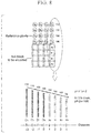
- FIG. 8 it is assumed that the block to be encoded is a 4 ⁇ 4 block.
- the intraframe prediction encoding apparatus 100 estimates the pixel value y of the predicted pixel from the gradients ⁇ ' indicated by the pixel values of these reference pixels as shown in Equation (7).
- the gradients ⁇ ' may be obtained with respect to four lines of A, B, C, and D independently, and these gradients may be determined as estimation results.
- the common gradient ⁇ ' may be obtained by calculating the average value thereof, and this common gradient may be determined as an estimation result.
- the predicted signal is generated in accordance with Equation (7).
- the intraframe prediction encoding apparatus 100 of the present invention configured as shown in FIG. 7 to notify the image decoding side of the gradient ⁇ '. Accordingly, in comparison to the intraframe prediction encoding apparatus 10 configured as shown in FIG. 2 , additional information becomes unnecessary, and thus the encoded data amount can be reduced to that extent.
- FIG. 9 illustrates a flowchart executed by the intraframe prediction encoding apparatus 100 according to the present embodiment. The operation executed by the intraframe prediction encoding apparatus 100 will now be described in accordance with the flowchart.
- the intraframe prediction encoding apparatus 100 initializes the minimum value J min of the rate distortion cost J i to be used in step S306 described later to MAXcost that indicates a sufficiently large value (i.e. a value which has no possibility that the rate distortion cost J i actually takes).
- step S303 a loop (where, variable is i) that designates the prediction mode taken by the block to be encoded is started.
- the prediction modes that can be taken by the block to be encoded vary depending on the position within an image at which the block to be encoded exists, and thus ⁇ is defined as a set of all prediction modes that can be taken by the block to be encoded. As an initial value, ⁇ (where, ⁇ is the smallest prediction mode number among the modes that can be taken) is assigned to i.
- step S304 as described with reference to FIG. 8 , the gradient ⁇ i ' for one-pixel distance is estimated using k reference pixels in the prediction direction prescribed by the selected prediction mode i. This estimation is performed using a least-square method and so on.
- step S305 a predicted signal to which a gradient is applied is generated in accordance with Equation (7) using the gradient ⁇ i ' obtained in step S304.
- step S306 a rate distortion cost Ji is obtained.
- SSD is the sum of the squares of the absolute values of prediction errors
- ⁇ is a Lagrange multiplier for prediction mode determination
- R block is a code amount generated when the block to be encoded is encoded in the selected prediction mode i.
- step S307 it is determined whether or not the cost Ji calculated in step S306 is the minimum by deciding whether or not Equation (9) is satisfied. J i ⁇ J min
- step S306 If it is decided that the cost J i calculated in step S306 is below the minimum cost J min according to the decision in step S307, the processing proceeds to step S308, the value of the prediction mode i and the gradient ⁇ i ' at that time are recorded, and J min is updated as in the following Equations (10) to (12).
- step S306 if it is decided that the cost J i calculated in step S306 is not below the minimum cost J min according to the decision in step S307, the process in step S308 is not performed, and the update process indicated by Equations (10) to (12) is not performed.
- the above-described cost calculation process is performed in a manner in which a loop for the prediction mode is repeated within the range of i ⁇ (i.e. with respect to all prediction modes that can be taken).
- step S309 only the obtained best_mode is encoded.
- a generally used method such as arithmetic coding, may be used as an encoding scheme.
- the encoding information is inserted into a header and so on.
- step S310 a predicted signal to which a gradient is applied is generated using the obtained best_mode and the gradient ⁇ ', and the block to be encoded is encoded.
- the concept of the present invention can be applied to sizes which are different from the size of the 4 ⁇ 4 block.
- the present invention can be applied to not only the luminance signal but also the chrominance signal in the same manner.
- FIG. 10 illustrates an intraframe prediction decoding apparatus 200 according to an embodiment of the present invention that decodes the encoded data generated by the intraframe prediction encoding apparatus 100 according to the present embodiment configured as shown in FIG. 7 .
- the intraframe prediction decoding apparatus 200 includes a prediction mode decoding unit 401, a gradient estimation unit 402, a predicted signal generation unit 403, a residual signal decoding unit 404, and a decoded image generation unit 405.
- the prediction mode decoding unit 401 decodes information on the prediction mode inserted into a header and so on of the encoded data.
- the gradient estimation unit 402 estimates the gradient of the predicted signal estimated by the intraframe prediction encoding apparatus 100 by executing the same estimation algorithm as that of the intraframe prediction encoding apparatus 100 based on the reference pixels prescribed by the prediction mode that is decoded by the prediction mode decoding unit 401.
- the predicted signal generation unit 403 generates the predicted signal to which the gradient is applied which is generated by the intraframe prediction encoding apparatus 100 based on the prediction mode decoded by the prediction mode decoding unit 401 and the gradient estimated by the gradient estimation unit 402.
- the residual signal decoding unit 404 decodes the residual signal encoded by the intraframe prediction encoding apparatus 100 from the encoded data.
- the decoded image generation unit 405 generates the decoded image signal based on the predicted signal generated by the predicted signal generation unit 403 and the residual signal decoded by the residual signal decoding unit 404.
- FIG. 11 illustrates a flowchart executed by the intraframe prediction decoding apparatus 200 according to the present embodiment. The process executed by the intraframe prediction decoding apparatus 200 will now be described in accordance with the flowchart.
- the intraframe prediction decoding apparatus 200 Upon input of the encoded data generated by the intraframe prediction encoding apparatus 100, as shown in the flowchart of FIG. 11 , in step S401, the intraframe prediction decoding apparatus 200 according to the present embodiment decodes information on best_mode inserted into the header and so on of the input encoded data.
- step S402 by executing the same estimation algorithm as that of the intraframe prediction encoding apparatus 100 based on the reference pixels prescribed by the decoded best_mode, the gradient of the predicted signal estimated by the intraframe prediction encoding apparatus 100 is estimated.
- step S403 the predicted signal to which the gradient is applied generated by the intraframe prediction encoding apparatus 100 is generated in accordance with the decoded best_mode and the estimated gradient.
- step S404 the residual signal (i.e. the difference between the (original) image signal and the predicted signal) encoded by the intraframe prediction encoding apparatus 100 is decoded from the input encoded data.
- step S405 the decoded image signal is generated based on the generated predicted signal to which the gradient is applied and the decoded residual signal.
- the intraframe prediction decoding apparatus 200 configured as shown in FIG. 10 decodes the encoded data generated by the intraframe prediction encoding apparatus 100 configured as shown in FIG. 7 .
- the intraframe prediction encoding apparatus 100 shown in FIG. 7 adopts the construction in which the optimum prediction mode encoding unit 310 is provided and, as described in step S309 in the flowchart of FIG. 9 , the optimum prediction mode encoding unit 310 reads only best_mode from the optimum encoding information storage unit 308, and decodes the read best_mode, it is also possible to adopt a construction in which the optimum prediction mode encoding unit 310 reads the best_mode and the gradient ⁇ ' from the optimum encoding information storage unit 308 and decodes the read best_mode and gradient ⁇ '.
- the optimum encoding information encoding unit 312 is provided instead of the optimum prediction mode encoding unit 310, and as described in step S309p of the flowchart in FIG. 13 (which corresponds to the flowchart of FIG. 9 ), the optimum encoding information encoding unit 312 reads the best_mode and the gradient ⁇ ' from the optimum encoding information storage unit 308, and encodes the read best_mode and gradient ⁇ '.
- the intraframe prediction decoding apparatus 20 as shown in FIG. 5 is used instead of the intraframe prediction decoding apparatus 200 as shown in FIG. 10 .
- FIGS. 14 and 15 illustrate the results of experiments.
- the experimental conditions are as follows.
- the horizontal axis in FIGS. 14 and 15 represents a gradient adjustment coefficient determined as an optimum amount, and the vertical axis represents its selection probability.
- the probability that the conventional scheme is adopted is varied depending on ⁇ .
- the scheme according to the present invention is selected in the range of about 20 to 80% even if ⁇ is changed.
- the code amount of the gradient information is not considered, it can be recognized that the rate distortion characteristics are clearly improved.
- the intraframe prediction encoding apparatus 10 configured as shown in FIG. 2 , three kinds of encoding performances by (1) a conventional scheme, (2) a scheme according to the present invention without the gradient information amount taken into consideration (in the case in which the code amount of the gradient information is not considered), and (3) a scheme according to the present invention with the gradient information amount taken into consideration (in the case in which the code amount of the gradient information is considered) were compared with one another.
- FIG. 16 illustrates the result of experiments.
- the obtained gradient information amount is calculated by measuring 0th-order entropy (i.e. the lower limit of the number of bits (the ideal number of bits) required to encode the information without loss) from the selection probability distribution of the respective images to be encoded as shown in FIGS. 14 and 15 .
- the scheme according to the present invention without the gradient information amount taken into consideration always has a better performance than that according to the conventional scheme.
- the scheme according to the present invention with the gradient information amount taken into consideration frequently shows a better performance than that according to the conventional scheme, but sometimes it is slightly deteriorated in comparison to the conventional scheme.
- the advantageous effect of the present invention is increased. This is conceivable because the ratio of the gradient information amount becomes relatively lower.
- the present invention can obtain an improvement in the rate distortion characteristics under high-bit rate conditions.
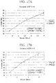
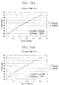
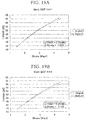
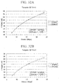
- FIGS. 17A to 35 illustrate the results of experiments. It is noted that in the experiments with respect to the present invention, the bit rate was obtained with the gradient information amount taken into consideration.
- the solid lines indicate the experimental results according to the present invention, and the dotted lines (“Original") indicate the experimental results according to the conventional scheme.
- ⁇ PSNR and ⁇ Bitrate which indicate the average values of the differences between the experimental result according to the scheme of the present invention and the experimental result according to the conventional scheme, were calculated using the standard calculation procedure described in the following reference document.
- FIGS. 17A and 17B illustrate the experimental results in the case in which the kind of image is "Container", the image size is QCIF, and the block size is 4 ⁇ 4.
- the experimental results in FIG. 17A show an image quality improvement of 0.114 dB on average with respect to PSNR and a generated code amount reduction of 0.873 % on average with respect to the bit rate.
- the experimental results in FIG. 17B show an image quality improvement of 0.246 dB on average with respect to PSNR and a generated code amount reduction of 1.69 % on average with respect to the bit rate.
- FIGS. 18A and 18B illustrate the experimental results in the case in which the kind of image is "Foreman", the image size is QCIF, and the block size is 4 ⁇ 4.
- the experimental results in FIG. 18A show an image quality improvement of 0.273 dB on average with respect to PSNR and a generated code amount reduction of 2.20 % on average with respect to the bit rate.
- the experimental results in FIG. 18B show an image quality improvement of 0.417 dB on average with respect to PSNR and a generated code amount reduction of 3.06 % on average with respect to the bit rate.
- FIGS. 19A and 19B illustrate the experimental results in the case in which the kind of image is "Silent", the image size is QCIF, and the block size is 4 ⁇ 4.
- the experimental results in FIG. 19A show an image quality improvement of 0.223 dB on average with respect to PSNR and a generated code amount reduction of 1.62 % on average with respect to the bit rate.
- the experimental results in FIG. 19B show an image quality improvement of 0.337 dB on average with respect to PSNR and a generated code amount reduction of 2.12 % on average with respect to the bit rate.
- FIGS. 20A and 20B illustrate the experimental results in the case in which the kind of image is "Paris", the image size is CIF, and the block size is 4 ⁇ 4.
- the experimental results in FIG. 20A show an image quality improvement of 0.167 dB on average with respect to PSNR and a generated code amount reduction of 1.28 % on average with respect to the bit rate.
- the experimental results in FIG. 20B show an image quality improvement of 0.347 dB on average with respect to PSNR and a generated code amount reduction of 2.32 % on average with respect to the bit rate.
- FIGS. 21A and 21B illustrate the experimental results in the case in which the kind of image is "Foreman", the image size is CIF, and the block size is 4 ⁇ 4.
- the experimental results in FIG. 21A show an image quality improvement of 0.147 dB on average with respect to PSNR and a generated code amount reduction of 1.32 % on average with respect to the bit rate.
- the experimental results in FIG. 21B show an image quality improvement of 0.280 dB on average with respect to PSNR and a generated code amount reduction of 2.28 % on average with respect to the bit rate.
- FIGS. 22A and 22B illustrate the experimental results in the case in which the kind of image is "Mobile", the image size is CIF, and the block size is 4 ⁇ 4.
- the experimental results in FIG. 22A show an image quality improvement of 0.395 dB on average with respect to PSNR and a generated code amount reduction of 2.70 % on average with respect to the bit rate.
- the experimental results in FIG. 22B show an image quality improvement of 0.546 dB on average with respect to PSNR and a generated code amount reduction of 3.47 % on average with respect to the bit rate.
- FIGS. 23A and 23B illustrate the experimental results in the case in which the kind of image is "Tempete", the image size is CIF, and the block size is 4 ⁇ 4.
- the experimental results in FIG. 23A show an image quality improvement of 0.282 dB on average with respect to PSNR and a generated code amount reduction of 2.04 % on average with respect to the bit rate.
- the experimental results in FIG. 23B show an image quality improvement of 0.405 dB on average with respect to PSNR and a generated code amount reduction of 3.60 % on average with respect to the bit rate.
- FIGS. 24A and 24B illustrate the experimental results in the case in which the kind of image is "Whale Show", the image size is SD, and the block size is 4 ⁇ 4.
- the experimental results in FIG. 24A show an image quality improvement of 0.254 dB on average with respect to PSNR and a generated code amount reduction of 1.99 % on average with respect to the bit rate.
- the experimental results in FIG. 24B show an image quality improvement of 0.376 dB on average with respect to PSNR and a generated code amount reduction of 2.62 % on average with respect to the bit rate.
- FIGS. 25A and 25B illustrate the experimental results in the case in which the kind of image is "Crowded Crosswalk", the image size is SD, and the block size is 4 ⁇ 4.
- the experimental results in FIG. 25A show an image quality improvement of 0.118 dB on average with respect to PSNR and a generated code amount reduction of 1.06 % on average with respect to the bit rate.
- the experimental results in FIG. 25B show an image quality improvement of 0.201 dB on average with respect to PSNR and a generated code amount reduction of 1.72 % on average with respect to the bit rate.
- FIGS. 26A and 26B illustrate the experimental results in the case in which the kind of image is "Container", the image size is QCIF, and the block size is 8 ⁇ 8.
- the experimental results in FIG. 26A show an image quality improvement of 0.0794 dB on average with respect to PSNR and a generated code amount reduction of 0.688 % on average with respect to the bit rate.
- the experimental results in FIG. 26B show an image quality improvement of 0.188 dB on average with respect to PSNR and a generated code amount reduction of 1.60 % on average with respect to the bit rate.
- FIGS. 27A and 27B illustrate the experimental results in the case in which the kind of image is "Foreman", the image size is QCIF, and the block size is 8 ⁇ 8.
- the experimental results in FIG. 27A show an image quality improvement of 0.179 dB on average with respect to PSNR and a generated code amount reduction of 1.61 % on average with respect to the bit rate.
- the experimental results in FIG. 27B show an image quality improvement of 0.368 dB on average with respect to PSNR and a generated code amount reduction of 3.23 % on average with respect to the bit rate.
- FIGS. 28A and 28B illustrate the experimental results in the case in which the kind of image is "Silent", the image size is QCIF, and the block size is 8 ⁇ 8.
- the experimental results in FIG. 28A show an image quality improvement of 0.234 dB on average with respect to PSNR and a generated code amount reduction of 1.99 % on average with respect to the bit rate.
- the experimental results in FIG. 28B show an image quality improvement of 0.369 dB on average with respect to PSNR and a generated code amount reduction of 3.07 % on average with respect to the bit rate.
- FIGS. 29A and 29B illustrate the experimental results in the case in which the kind of image is "Paris", the image size is CIF, and the block size is 8 ⁇ 8.
- the experimental results in FIG. 29A show an image quality improvement of 0.157 dB on average with respect to PSNR and a generated code amount reduction of 1.29 % on average with respect to the bit rate.
- the experimental results in FIG. 29B show an image quality improvement of 0.313 dB on average with respect to PSNR and a generated code amount reduction of 2.49 % on average with respect to the bit rate.
- FIGS. 30A and 30B illustrate the experimental results in the case in which the kind of image is "Foreman", the image size is CIF, and the block size is 8 ⁇ 8.
- the experimental results in FIG. 30A show an image quality improvement of 0.0956 dB on average with respect to PSNR and a generated code amount reduction of 0.939 % on average with respect to the bit rate.
- the experimental results in FIG. 30B show an image quality improvement of 0.283 dB on average with respect to PSNR and a generated code amount reduction of 2.71 % on average with respect to the bit rate.
- FIGS. 31A and 31B illustrate the experimental results in the case in which the kind of image is "Mobile", the image size is CIF, and the block size is 8 ⁇ 8.
- the experimental results in FIG. 31A show an image quality improvement of 0.202 dB on average with respect to PSNR and a generated code amount reduction of 1.39 % on average with respect to the bit rate.
- the experimental results in FIG. 31B show an image quality improvement of 0.285 dB on average with respect to PSNR and a generated code amount reduction of 1.94 % on average with respect to the bit rate.
- FIGS. 32A and 32B illustrate the experimental results in the case in which the kind of image is "Tempete", the image size is CIF, and the block size is 8 ⁇ 8.
- the experimental results in FIG. 32A show an image quality improvement of 0.210 dB on average with respect to PSNR and a generated code amount reduction of 1.69 % on average with respect to the bit rate.
- the experimental results in FIG. 32B show an image quality improvement of 0.330 dB on average with respect to PSNR and a generated code amount reduction of 2.60 % on average with respect to the bit rate.
- FIGS. 33A and 33B illustrate the experimental results in the case in which the kind of image is "Whale Show", the image size is SD, and the block size is 8 ⁇ 8.
- the experimental results in FIG. 33A show an image quality improvement of 0.183 dB on average with respect to PSNR and a generated code amount reduction of 1.70 % on average with respect to the bit rate.
- the experimental results in FIG. 33B show an image quality improvement of 0.333 dB on average with respect to PSNR and a generated code amount reduction of 3.00 % on average with respect to the bit rate.
- FIGS. 34A and 34B illustrate the experimental results in the case in which the kind of image is "Crowded Crosswalk", the image size is SD, and the block size is 8 ⁇ 8.
- the experimental results in FIG. 34A show an image quality improvement of 0.101 dB on average with respect to PSNR and a generated code amount reduction of 1.08 % on average with respect to the bit rate.
- the experimental results in FIG. 34B show an image quality improvement of 0.225 dB on average with respect to PSNR and a generated code amount reduction of 2.32 % on average with respect to the bit rate.
- FIG. 35 illustrates a table of the experimental results as shown in FIGS. 17A to 34B .
- the PSNR can be improved and the generated code amount can be reduced in comparison to the conventional scheme.
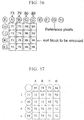
- prediction mode 2 an average value prediction: a mode in which a predicted value with respect to a given block is obtained by interpolating pixel values in an oblique direction with reference to neighboring pixels of the upper side block and neighboring pixels of the left side block
- the prediction mode of the intraframe prediction is H.264/MPEG-4AVC
- Ri denotes the signal value of the i-th reference pixel available when the DC prediction is used
- m denotes the total number of available reference pixels.
- >> denotes a bit shift process
- an amount corresponding to the gradient that further reduces a prediction error is obtained by adding ⁇ thereto, and the amount is encoded as the gradient information (where, ⁇ is "a value added to the pixel value" in the present invention, and may have any one of positive and negative values).
- a predicted signal of a given block is determined by obtaining, in addition to 72 as shown in FIG. 37 , three different candidates of 71, 72, and 73 as follows, and selecting one of them that realizes the best cost.
- the above calculation is the same process of adding four pixel values, dividing the added value by 4, and rounding to the nearest whole number.
- the present embodiment can realize the prediction that can flexibly reduce the residual signal based on the property of an image by further adding ⁇ in the same manner for the respective cases.
- a horizontal gradient and a vertical gradient are determined from a block positioned above the new block in a diagonal direction, and based on these gradients, an encoder predicts image information based on image processing of any one of a block neighboring in the horizontal direction to the new block, a block vertically neighboring to the new block, and a block neighboring in the vertical direction to the new block. Accordingly, this scheme is fundamentally different from the scheme according to the present invention
- the present invention can be applied to the encoding of an image using an intraframe prediction, and by generating a prediction signal to which a gradient is applied so that the prediction signal matches an actual image, a prediction error can be reduced, and thus compression efficiency can be improved.
Landscapes
- Engineering & Computer Science (AREA)
- Multimedia (AREA)
- Signal Processing (AREA)
- Compression Or Coding Systems Of Tv Signals (AREA)
Applications Claiming Priority (3)
| Application Number | Priority Date | Filing Date | Title |
|---|---|---|---|
| JP2007267614 | 2007-10-15 | ||
| EP08839649A EP2200324A4 (fr) | 2007-10-15 | 2008-10-14 | Dispositif de codage d'image et dispositif de décodage d'image, procédé de codage d'image et procédé de décodage d'image, programme pour les dispositifs et les procédés, et programme d'enregistrement de support d'enregistrement |
| PCT/JP2008/068547 WO2009051091A1 (fr) | 2007-10-15 | 2008-10-14 | Dispositif de codage d'image et dispositif de décodage d'image, procédé de codage d'image et procédé de décodage d'image, programme pour les dispositifs et les procédés, et programme d'enregistrement de support d'enregistrement |
Related Parent Applications (1)
| Application Number | Title | Priority Date | Filing Date |
|---|---|---|---|
| EP08839649A Division EP2200324A4 (fr) | 2007-10-15 | 2008-10-14 | Dispositif de codage d'image et dispositif de décodage d'image, procédé de codage d'image et procédé de décodage d'image, programme pour les dispositifs et les procédés, et programme d'enregistrement de support d'enregistrement |
Publications (1)
| Publication Number | Publication Date |
|---|---|
| EP3410712A1 true EP3410712A1 (fr) | 2018-12-05 |
Family
ID=40567355
Family Applications (3)
| Application Number | Title | Priority Date | Filing Date |
|---|---|---|---|
| EP22210634.6A Ceased EP4164220A1 (fr) | 2007-10-15 | 2008-10-14 | Appareils de codage et de décodage d'image, procédés de codage et de décodage d'image |
| EP18184537.1A Ceased EP3410712A1 (fr) | 2007-10-15 | 2008-10-14 | Appareils de codage et de décodage d'images, procédés de codage et de décodage d'images, programmes associés et supports d'enregistrement enregistrés avec les programmes |
| EP08839649A Ceased EP2200324A4 (fr) | 2007-10-15 | 2008-10-14 | Dispositif de codage d'image et dispositif de décodage d'image, procédé de codage d'image et procédé de décodage d'image, programme pour les dispositifs et les procédés, et programme d'enregistrement de support d'enregistrement |
Family Applications Before (1)
| Application Number | Title | Priority Date | Filing Date |
|---|---|---|---|
| EP22210634.6A Ceased EP4164220A1 (fr) | 2007-10-15 | 2008-10-14 | Appareils de codage et de décodage d'image, procédés de codage et de décodage d'image |
Family Applications After (1)
| Application Number | Title | Priority Date | Filing Date |
|---|---|---|---|
| EP08839649A Ceased EP2200324A4 (fr) | 2007-10-15 | 2008-10-14 | Dispositif de codage d'image et dispositif de décodage d'image, procédé de codage d'image et procédé de décodage d'image, programme pour les dispositifs et les procédés, et programme d'enregistrement de support d'enregistrement |
Country Status (10)
| Country | Link |
|---|---|
| US (1) | US9008173B2 (fr) |
| EP (3) | EP4164220A1 (fr) |
| JP (1) | JP4987085B2 (fr) |
| KR (1) | KR101159292B1 (fr) |
| CN (1) | CN101822062B (fr) |
| BR (1) | BRPI0818590B1 (fr) |
| CA (1) | CA2701893C (fr) |
| RU (1) | RU2479940C2 (fr) |
| TW (1) | TWI415478B (fr) |
| WO (1) | WO2009051091A1 (fr) |
Families Citing this family (25)
| Publication number | Priority date | Publication date | Assignee | Title |
|---|---|---|---|---|
| EP3337171A1 (fr) * | 2009-10-22 | 2018-06-20 | Thomson Licensing | Procédés et appareil pour un mode de prédiction interne à courant continu en codage et décodage vidéo |
| JP2011151682A (ja) * | 2010-01-22 | 2011-08-04 | Sony Corp | 画像処理装置および方法 |
| JP2011166218A (ja) * | 2010-02-04 | 2011-08-25 | Victor Co Of Japan Ltd | 画像信号符号化装置、画像信号符号化方法、画像信号復号装置、及び、画像信号復号方法 |
| JP5259879B2 (ja) * | 2010-07-15 | 2013-08-07 | 株式会社東芝 | 画像符号化方法及び画像復号化方法 |
| AU2015201843B2 (en) * | 2010-07-15 | 2017-03-09 | Kabushiki Kaisha Toshiba | Image encoding method and image decoding method |
| AU2015202668B2 (en) * | 2010-07-16 | 2015-12-10 | Samsung Electronics Co., Ltd. | Method and apparatus for encoding and decoding image through intra prediction |
| KR101530284B1 (ko) | 2010-07-16 | 2015-06-19 | 삼성전자주식회사 | 영상의 인트라 예측 부호화, 복호화 방법 및 장치 |
| CN103299637B (zh) | 2011-01-12 | 2016-06-29 | 三菱电机株式会社 | 图像编码装置、图像译码装置、图像编码方法以及图像译码方法 |
| WO2012098878A1 (fr) | 2011-01-19 | 2012-07-26 | パナソニック株式会社 | Procédé de codage vidéo et procédé de décodage vidéo |
| HUE067788T2 (hu) * | 2011-04-25 | 2024-11-28 | Lg Electronics Inc | Intra predikciós eljárás videó dekódoláshoz és videó kódoláshoz |
| EP2721827A4 (fr) * | 2011-06-20 | 2016-03-02 | Mediatek Singapore Pte Ltd | Procédé et appareil d'intraprédiction directionnelle |
| JP5389297B2 (ja) * | 2011-06-24 | 2014-01-15 | 三菱電機株式会社 | 画像復号装置及び画像復号方法 |
| JP5795525B2 (ja) | 2011-12-13 | 2015-10-14 | 日本電信電話株式会社 | 画像符号化方法,画像復号方法,画像符号化装置,画像復号装置,画像符号化プログラムおよび画像復号プログラム |
| TWI577185B (zh) * | 2012-04-16 | 2017-04-01 | Jvc Kenwood Corp | Dynamic image decoding device, dynamic image decoding method, and dynamic image decoding program |
| EP2870753B1 (fr) | 2012-07-04 | 2018-04-25 | Thomson Licensing | Prédiction spatiale avec nombre accru de modes de codage possibles |
| JP2014082541A (ja) * | 2012-10-12 | 2014-05-08 | National Institute Of Information & Communication Technology | 互いに類似した情報を含む複数画像のデータサイズを低減する方法、プログラムおよび装置 |
| KR20140072231A (ko) * | 2012-11-26 | 2014-06-13 | 한국전자통신연구원 | 율-왜곡 비용의 확률분포를 이용한 비디오 부호화기의 고속 예측모드 결정 방법 |
| GB2516425B (en) | 2013-07-17 | 2015-12-30 | Gurulogic Microsystems Oy | Encoder and decoder, and method of operation |
| JP2015070488A (ja) * | 2013-09-30 | 2015-04-13 | Kddi株式会社 | 動画像符号化装置、動画像復号装置、動画像符号化方法、動画像復号方法、およびプログラム |
| JP6468703B2 (ja) * | 2013-12-20 | 2019-02-13 | キヤノン株式会社 | 動き検出装置、動き検出方法及びプログラム |
| US9743092B2 (en) * | 2015-10-13 | 2017-08-22 | Nokia Technologies Oy | Video coding with helper data for spatial intra-prediction |
| US10390021B2 (en) | 2016-03-18 | 2019-08-20 | Mediatek Inc. | Method and apparatus of video coding |
| CN108259913A (zh) * | 2016-12-29 | 2018-07-06 | 北京大学深圳研究生院 | 一种用于帧间预测帧中的帧内预测方法 |
| BR112021000569A2 (pt) * | 2018-07-20 | 2021-04-06 | Huawei Technologies Co., Ltd. | Método e dispositivo de interpolação de amostra de referência de intrapredição bidirecional |
| WO2020171046A1 (fr) * | 2019-02-20 | 2020-08-27 | Panasonic Intellectual Property Corporation Of America | Codeur d'image et décodeur d'image |
Citations (2)
| Publication number | Priority date | Publication date | Assignee | Title |
|---|---|---|---|---|
| JPH10224804A (ja) | 1996-09-20 | 1998-08-21 | At & T Corp | ビデオの画像コーディング及びイントラコーディングのための暗黙の係数予測及び走査適合化を提供するビデオコーダー |
| US20050243920A1 (en) * | 2004-04-28 | 2005-11-03 | Tomokazu Murakami | Image encoding/decoding device, image encoding/decoding program and image encoding/decoding method |
Family Cites Families (12)
| Publication number | Priority date | Publication date | Assignee | Title |
|---|---|---|---|---|
| EP1691560B1 (fr) * | 1996-09-20 | 2017-03-08 | AT&T Corp. | Codeur vidéo fournissant une prédiction implicite des coefficients pour le codage d'images et le codage en intra de la vidéo |
| AR016812A1 (es) | 1997-08-14 | 2001-08-01 | Samsung Electronics Co Ltd | Metodo para transmitir informacion de video comprimida, disposiciones de compresion y de grabacion de video y aparato de reproduccion de video |
| ES2788534T3 (es) * | 2002-05-28 | 2020-10-21 | Dolby Int Ab | Método y sistemas para la estimación, comunicación y organización de modos de intra-predicción de imágenes |
| KR100987765B1 (ko) | 2003-09-30 | 2010-10-13 | 삼성전자주식회사 | 동영상 부호화기에서의 예측 수행 방법 및 장치 |
| US7369707B2 (en) * | 2003-10-28 | 2008-05-06 | Matsushita Electric Industrial Co., Ltd. | Intra-picture prediction coding method |
| CN100536573C (zh) * | 2004-01-16 | 2009-09-02 | 北京工业大学 | 基于方向的dc预测方法及用于视频编码的帧内预测方法 |
| EP1808024B1 (fr) | 2004-11-04 | 2013-04-17 | Thomson Licensing | Prediction en mode intra rapide pour codeur video |
| FR2881898A1 (fr) * | 2005-02-10 | 2006-08-11 | Thomson Licensing Sa | Procede et dispositif de codage d'une image video en mode inter ou intra |
| WO2007032600A1 (fr) | 2005-07-21 | 2007-03-22 | Samsung Electronics Co., Ltd. | Procede et appareil de codage et de decodage d'un signal video par extension de l'application d'intra-prediction directionnelle |
| KR100750145B1 (ko) * | 2005-12-12 | 2007-08-21 | 삼성전자주식회사 | 영상의 인트라 예측 부호화, 복호화 방법 및 장치 |
| KR101311402B1 (ko) * | 2006-03-23 | 2013-09-25 | 삼성전자주식회사 | 영상의 부호화 방법 및 장치, 복호화 방법 및 장치 |
| JP4350102B2 (ja) | 2006-03-30 | 2009-10-21 | 株式会社クボタ | 乗用型田植機 |
-
2008
- 2008-10-14 JP JP2009538086A patent/JP4987085B2/ja active Active
- 2008-10-14 US US12/682,035 patent/US9008173B2/en active Active
- 2008-10-14 CA CA2701893A patent/CA2701893C/fr active Active
- 2008-10-14 EP EP22210634.6A patent/EP4164220A1/fr not_active Ceased
- 2008-10-14 EP EP18184537.1A patent/EP3410712A1/fr not_active Ceased
- 2008-10-14 EP EP08839649A patent/EP2200324A4/fr not_active Ceased
- 2008-10-14 WO PCT/JP2008/068547 patent/WO2009051091A1/fr not_active Ceased
- 2008-10-14 CN CN2008801115240A patent/CN101822062B/zh active Active
- 2008-10-14 KR KR1020107007476A patent/KR101159292B1/ko active Active
- 2008-10-14 TW TW97139318A patent/TWI415478B/zh active
- 2008-10-14 BR BRPI0818590-5A patent/BRPI0818590B1/pt active IP Right Grant
- 2008-10-14 RU RU2010113343/07A patent/RU2479940C2/ru active
Patent Citations (2)
| Publication number | Priority date | Publication date | Assignee | Title |
|---|---|---|---|---|
| JPH10224804A (ja) | 1996-09-20 | 1998-08-21 | At & T Corp | ビデオの画像コーディング及びイントラコーディングのための暗黙の係数予測及び走査適合化を提供するビデオコーダー |
| US20050243920A1 (en) * | 2004-04-28 | 2005-11-03 | Tomokazu Murakami | Image encoding/decoding device, image encoding/decoding program and image encoding/decoding method |
Non-Patent Citations (9)
| Title |
|---|
| "ITU-T Study Group 16-Question 6/16: ''Draft new Corrigendum 1 to H.264", ADVANCED VIDEO CODING FOR GENERIC AUDIOVISUAL SERVICES, 2005, pages 116 - 135 |
| MARTA KARCZEWICZ: "Improved Intra Coding", 32. VCEG MEETING; 80. MPEG MEETING; 23-4-2007 - 27-4-2007; SAN JOSE;(VIDEO CODING EXPERTS GROUP OF ITU-T SG.16),, no. VCEG-AF15, 19 April 2007 (2007-04-19), XP030003536, ISSN: 0000-0068 * |
| MATSUO S ET AL: "Weighted intra pred", 33. VCEG MEETING; 82. MPEG MEETING; 20-10-2007 - 20-10-2007; SHENZHEN;(VIDEO CODING EXPERTS GROUP OF ITU-T SG.16),, no. VCEG-AG18, 20 October 2007 (2007-10-20), XP030003622, ISSN: 0000-0095 * |
| PENG ZHANG ET AL: "Multiple modes intra-prediction in intra coding", 2004 IEEE INTERNATIONAL CONFERENCE ON MULTIMEDIA AND EXPO : JUNE 27 - 30, 2004, TAIPEI, TAIWAN, IEEE OPERATIONS CENTER, PISCATAWAY, NJ, vol. 1, 27 June 2004 (2004-06-27), pages 419 - 422, XP010770800, ISBN: 978-0-7803-8603-7, DOI: 10.1109/ICME.2004.1394218 * |
| SAKAE OKUBO; SHINYA KADONO; YOSHIHIRO KIKUCHI; TERUHIKO SUZUKI, REVISED VERSION H.264/AVC TEXTBOOK, 2006, pages 106 - 112 |
| TAICHIRO SHIODERA ET AL: "Block Based Extra/Inter-Polating Prediction for Intra Coding", IMAGE PROCESSING, 2007. ICIP 2007. IEEE INTERNATIONAL CONFERENCE ON, IEEE, PI, 1 September 2007 (2007-09-01), pages VI - 445, XP031158358, ISBN: 978-1-4244-1436-9 * |
| TAICHIRO SHIODERA; AKIYUKI TANIZAWA; TAKESHI CHUJOH: "Block Based Extra/lntra-polating Prediction for Intra Coding", PICTURE CODING SYMPOSIUM OF JAPAN, 21ST SYMPOSIUM DATA, 2006, pages 123 - 124 |
| XIANG LI ET AL: "Gradient Intra Prediction for Coding of Computer Animated Videos", 2006 IEEE 8TH WORKSHOP ON MULTIMEDIA SIGNAL PROCESSING, MMSP'06, VICTORIA, CANADA, 1 October 2006 (2006-10-01), pages 50 - 53, XP031011019, ISBN: 978-0-7803-9751-4 * |
| ZHANG NAN ET AL: "Spatial prediction based intra-coding", 2004 IEEE INTERNATIONAL CONFERENCE ON MULTIMEDIA AND EXPO : JUNE 27 - 30, 2004, TAIPEI, TAIWAN, IEEE OPERATIONS CENTER, PISCATAWAY, NJ, vol. 1, 27 June 2004 (2004-06-27), pages 97 - 100, XP010770753, ISBN: 978-0-7803-8603-7, DOI: 10.1109/ICME.2004.1394134 * |
Also Published As
| Publication number | Publication date |
|---|---|
| BRPI0818590A2 (pt) | 2015-07-21 |
| TWI415478B (zh) | 2013-11-11 |
| JP4987085B2 (ja) | 2012-07-25 |
| CN101822062B (zh) | 2013-02-06 |
| CA2701893A1 (fr) | 2009-04-23 |
| KR101159292B1 (ko) | 2012-06-22 |
| WO2009051091A1 (fr) | 2009-04-23 |
| EP2200324A4 (fr) | 2012-10-17 |
| EP4164220A1 (fr) | 2023-04-12 |
| TW200931986A (en) | 2009-07-16 |
| EP2200324A1 (fr) | 2010-06-23 |
| US20100208803A1 (en) | 2010-08-19 |
| US9008173B2 (en) | 2015-04-14 |
| JPWO2009051091A1 (ja) | 2011-03-03 |
| CA2701893C (fr) | 2015-09-29 |
| BRPI0818590B1 (pt) | 2020-10-20 |
| KR20100065183A (ko) | 2010-06-15 |
| RU2479940C2 (ru) | 2013-04-20 |
| RU2010113343A (ru) | 2011-10-20 |
| CN101822062A (zh) | 2010-09-01 |
Similar Documents
| Publication | Publication Date | Title |
|---|---|---|
| US9008173B2 (en) | Image encoding and decoding apparatuses, image encoding and decoding methods, programs thereof, and recording media recorded with the programs | |
| KR100750128B1 (ko) | 영상의 인트라 예측 부호화, 복호화 방법 및 장치 | |
| KR101697056B1 (ko) | 화상 처리 장치 및 방법, 컴퓨터 판독가능 기록 매체 | |
| JP5625124B2 (ja) | 平面表現を用いる拡張されたイントラ予測符号化 | |
| KR101103699B1 (ko) | 영상 부호화 방법 및 복호 방법, 그들의 장치, 그들의 프로그램 및 프로그램을 기록한 기록매체 | |
| US8605784B2 (en) | Method and apparatus for encoding video, and method and apparatus for decoding video | |
| KR100727972B1 (ko) | 영상의 인트라 예측 부호화, 복호화 방법 및 장치 | |
| EP2924994A1 (fr) | Procédé et appareil permettant de décoder un signal vidéo | |
| US20110176614A1 (en) | Image processing device and method, and program | |
| KR20090095316A (ko) | 영상 인트라 예측 방법 및 장치 | |
| JP5594841B2 (ja) | 画像符号化装置及び画像復号装置 | |
| CN103583046A (zh) | 视频编码装置、视频解码装置、视频编码方法、视频解码方法、视频编码程序以及视频解码程序 | |
| JP7418152B2 (ja) | 画像符号化装置、画像符号化方法、画像復号装置、画像復号方法 | |
| JP5713719B2 (ja) | 動画像符号化装置 | |
| KR101802304B1 (ko) | 하다마드 변환을 이용한 부호화 방법 및 이러한 방법을 사용하는 장치 | |
| KR20180107067A (ko) | 영상 부호화/복호화 장치 및 방법 |
Legal Events
| Date | Code | Title | Description |
|---|---|---|---|
| PUAI | Public reference made under article 153(3) epc to a published international application that has entered the european phase |
Free format text: ORIGINAL CODE: 0009012 |
|
| STAA | Information on the status of an ep patent application or granted ep patent |
Free format text: STATUS: THE APPLICATION HAS BEEN PUBLISHED |
|
| AC | Divisional application: reference to earlier application |
Ref document number: 2200324 Country of ref document: EP Kind code of ref document: P |
|
| AK | Designated contracting states |
Kind code of ref document: A1 Designated state(s): AT BE BG CH CY CZ DE DK EE ES FI FR GB GR HR HU IE IS IT LI LT LU LV MC MT NL NO PL PT RO SE SI SK TR |
|
| STAA | Information on the status of an ep patent application or granted ep patent |
Free format text: STATUS: REQUEST FOR EXAMINATION WAS MADE |
|
| 17P | Request for examination filed |
Effective date: 20190514 |
|
| RBV | Designated contracting states (corrected) |
Designated state(s): AT BE BG CH CY CZ DE DK EE ES FI FR GB GR HR HU IE IS IT LI LT LU LV MC MT NL NO PL PT RO SE SI SK TR |
|
| STAA | Information on the status of an ep patent application or granted ep patent |
Free format text: STATUS: EXAMINATION IS IN PROGRESS |
|
| 17Q | First examination report despatched |
Effective date: 20201002 |
|
| P01 | Opt-out of the competence of the unified patent court (upc) registered |
Effective date: 20230522 |
|
| STAA | Information on the status of an ep patent application or granted ep patent |
Free format text: STATUS: THE APPLICATION HAS BEEN REFUSED |
|
| 18R | Application refused |
Effective date: 20240508 |