EP3411209B1 - Stecker für eine hydraulische rückflussleitung - Google Patents
Stecker für eine hydraulische rückflussleitung Download PDFInfo
- Publication number
- EP3411209B1 EP3411209B1 EP17702138.3A EP17702138A EP3411209B1 EP 3411209 B1 EP3411209 B1 EP 3411209B1 EP 17702138 A EP17702138 A EP 17702138A EP 3411209 B1 EP3411209 B1 EP 3411209B1
- Authority
- EP
- European Patent Office
- Prior art keywords
- connector
- shaped
- cage
- angle
- arms
- Prior art date
- Legal status (The legal status is an assumption and is not a legal conclusion. Google has not performed a legal analysis and makes no representation as to the accuracy of the status listed.)
- Active
Links
Images



Classifications
-
- F—MECHANICAL ENGINEERING; LIGHTING; HEATING; WEAPONS; BLASTING
- F02—COMBUSTION ENGINES; HOT-GAS OR COMBUSTION-PRODUCT ENGINE PLANTS
- F02M—SUPPLYING COMBUSTION ENGINES IN GENERAL WITH COMBUSTIBLE MIXTURES OR CONSTITUENTS THEREOF
- F02M55/00—Fuel-injection apparatus characterised by their fuel conduits or their venting means; Arrangements of conduits between fuel tank and pump F02M37/00
- F02M55/02—Conduits between injection pumps and injectors, e.g. conduits between pump and common-rail or conduits between common-rail and injectors
-
- B—PERFORMING OPERATIONS; TRANSPORTING
- B29—WORKING OF PLASTICS; WORKING OF SUBSTANCES IN A PLASTIC STATE IN GENERAL
- B29C—SHAPING OR JOINING OF PLASTICS; SHAPING OF MATERIAL IN A PLASTIC STATE, NOT OTHERWISE PROVIDED FOR; AFTER-TREATMENT OF THE SHAPED PRODUCTS, e.g. REPAIRING
- B29C33/00—Moulds or cores; Details thereof or accessories therefor
- B29C33/30—Mounting, exchanging or centering
- B29C33/306—Exchangeable mould parts, e.g. cassette moulds, mould inserts
-
- B—PERFORMING OPERATIONS; TRANSPORTING
- B29—WORKING OF PLASTICS; WORKING OF SUBSTANCES IN A PLASTIC STATE IN GENERAL
- B29C—SHAPING OR JOINING OF PLASTICS; SHAPING OF MATERIAL IN A PLASTIC STATE, NOT OTHERWISE PROVIDED FOR; AFTER-TREATMENT OF THE SHAPED PRODUCTS, e.g. REPAIRING
- B29C45/00—Injection moulding, i.e. forcing the required volume of moulding material through a nozzle into a closed mould; Apparatus therefor
- B29C45/17—Component parts, details or accessories; Auxiliary operations
- B29C45/26—Moulds
- B29C45/2673—Moulds with exchangeable mould parts, e.g. cassette moulds
-
- B—PERFORMING OPERATIONS; TRANSPORTING
- B29—WORKING OF PLASTICS; WORKING OF SUBSTANCES IN A PLASTIC STATE IN GENERAL
- B29C—SHAPING OR JOINING OF PLASTICS; SHAPING OF MATERIAL IN A PLASTIC STATE, NOT OTHERWISE PROVIDED FOR; AFTER-TREATMENT OF THE SHAPED PRODUCTS, e.g. REPAIRING
- B29C45/00—Injection moulding, i.e. forcing the required volume of moulding material through a nozzle into a closed mould; Apparatus therefor
- B29C45/17—Component parts, details or accessories; Auxiliary operations
- B29C45/26—Moulds
- B29C45/2673—Moulds with exchangeable mould parts, e.g. cassette moulds
- B29C45/2675—Mounting of exchangeable mould inserts
-
- F—MECHANICAL ENGINEERING; LIGHTING; HEATING; WEAPONS; BLASTING
- F02—COMBUSTION ENGINES; HOT-GAS OR COMBUSTION-PRODUCT ENGINE PLANTS
- F02M—SUPPLYING COMBUSTION ENGINES IN GENERAL WITH COMBUSTIBLE MIXTURES OR CONSTITUENTS THEREOF
- F02M55/00—Fuel-injection apparatus characterised by their fuel conduits or their venting means; Arrangements of conduits between fuel tank and pump F02M37/00
- F02M55/004—Joints; Sealings
- F02M55/005—Joints; Sealings for high pressure conduits, e.g. connected to pump outlet or to injector inlet
-
- F—MECHANICAL ENGINEERING; LIGHTING; HEATING; WEAPONS; BLASTING
- F02—COMBUSTION ENGINES; HOT-GAS OR COMBUSTION-PRODUCT ENGINE PLANTS
- F02M—SUPPLYING COMBUSTION ENGINES IN GENERAL WITH COMBUSTIBLE MIXTURES OR CONSTITUENTS THEREOF
- F02M57/00—Fuel-injectors combined or associated with other devices
- F02M57/02—Injectors structurally combined with fuel-injection pumps
- F02M57/022—Injectors structurally combined with fuel-injection pumps characterised by the pump drive
- F02M57/025—Injectors structurally combined with fuel-injection pumps characterised by the pump drive hydraulic, e.g. with pressure amplification
- F02M57/026—Construction details of pressure amplifiers, e.g. fuel passages or check valves arranged in the intensifier piston or head, particular diameter relationships, stop members, arrangement of ports or conduits
-
- F—MECHANICAL ENGINEERING; LIGHTING; HEATING; WEAPONS; BLASTING
- F02—COMBUSTION ENGINES; HOT-GAS OR COMBUSTION-PRODUCT ENGINE PLANTS
- F02M—SUPPLYING COMBUSTION ENGINES IN GENERAL WITH COMBUSTIBLE MIXTURES OR CONSTITUENTS THEREOF
- F02M2200/00—Details of fuel-injection apparatus, not otherwise provided for
- F02M2200/85—Mounting of fuel injection apparatus
-
- F—MECHANICAL ENGINEERING; LIGHTING; HEATING; WEAPONS; BLASTING
- F02—COMBUSTION ENGINES; HOT-GAS OR COMBUSTION-PRODUCT ENGINE PLANTS
- F02M—SUPPLYING COMBUSTION ENGINES IN GENERAL WITH COMBUSTIBLE MIXTURES OR CONSTITUENTS THEREOF
- F02M2200/00—Details of fuel-injection apparatus, not otherwise provided for
- F02M2200/85—Mounting of fuel injection apparatus
- F02M2200/856—Mounting of fuel injection apparatus characterised by mounting injector to fuel or common rail, or vice versa
-
- F—MECHANICAL ENGINEERING; LIGHTING; HEATING; WEAPONS; BLASTING
- F02—COMBUSTION ENGINES; HOT-GAS OR COMBUSTION-PRODUCT ENGINE PLANTS
- F02M—SUPPLYING COMBUSTION ENGINES IN GENERAL WITH COMBUSTIBLE MIXTURES OR CONSTITUENTS THEREOF
- F02M55/00—Fuel-injection apparatus characterised by their fuel conduits or their venting means; Arrangements of conduits between fuel tank and pump F02M37/00
- F02M55/002—Arrangement of leakage or drain conduits in or from injectors
Definitions
- the present invention relates to a low pressure fuel injector leakage return circuit and more particularly to the manufacture of circuit connectors.
- the present invention relates more particularly to a fuel injector connector, for example diesel, intended to connect the injector to the low pressure injector leakage return hydraulic circuit arranged in a motor vehicle and designed to recover the fuel from of the injector and store it in the fuel tank.
- a fuel injector connector for example diesel
- the leakage return hydraulic circuit includes both pipe elements and injector connectors.
- the circuit is connected to all injectors of the injection system and extends in line along the engine cylinders. It includes a first L-shaped connector for the injector located at one end of the engine block and, T-connectors for the following injectors, short pipe elements connecting the connectors to each other.
- an in-line four-cylinder engine includes an L-connector, three T-connectors and three short-pipe elements. A last longer pipe element than the others connects the last T-connector to the fuel tank.
- the connectors comprise a connection element, in L or T, locked in a tubular cage by a locking cap.
- the T-fittings include arms that make angles to each other.
- the T connectors are different from each other because the angles between the arms can be different on the same hydraulic circuit to facilitate its implementation on the engine.
- the three parts of the T-connector or L-connector are molded plastic.
- the L-shaped fittings require a different mold than the T-fittings.
- the production flexibility imposed by the innumerable variants of engine architectures shape, number of cylinders) is expensive and technically difficult.
- the object of the present invention is to solve these disadvantages by proposing an economical and flexible solution in the production of T and L connectors.
- the mold is a multi-cavity mold, all the indentations of which are identical, each comprising a body cavity and two arm prints.
- the arm fingerprints make an angle between them, so that the arms of the connecting element make said angle between them, said angle being in a plane perpendicular to the axis of the body.
- said angle is between 120 ° and 180 °, preferably about 150 °.
- the method of realization of the return hydraulic circuit is exclusively provided for a direct diesel fuel injection equipment for internal combustion engine.
- the circuit extends between a first L-shaped connector and a last T-shaped connector, and includes a plurality of T-shaped intermediate connectors as well as a plurality of pipe members.
- the arms of all the connectors are generally aligned in a main direction and a pipe element is arranged between two adjacent connectors.
- the method is characterized in that all the connectors are made according to the preceding embodiments.
- all the connectors are arranged so that the axes of the arms make an angle generally constant with the main direction, said angle being generally equal to 90 ° - B / 2.
- the T-connector arranged at the end of the circuit is rotated about the body axis by an angle generally equal to the inter-arm angle relative to the other T-connectors of the hydraulic circuit.
- the pipe elements have identical lengths.
- the hydraulic circuit comprises the T-connector described above and arranged at the end of the circuit and comprising the connectors made by the molding method described above.
- a leaking return hydraulic circuit 14 is a low pressure circuit connecting the fuel injectors 10 to a fuel tank.
- the hydraulic leakage return circuit 14 is connected to all the fuel injectors 10 and extends in line along the cylinders of the engine block (not shown).
- the high pressure fuel is fed to the fuel injectors 10 and the fuel is sprayed into the combustion chamber and a portion of the fuel returns to the fuel tank through the hydraulic leakage return circuit 14
- the hydraulic circuit 14 comprises a first L-shaped connector 13 for the injector located at one end of the engine block and, T-connectors 12 for the following injectors, short pipe elements 16 connecting the connectors to each other.
- the hydraulic circuit 14 is connected to a four-cylinder in-line engine (not shown) comprising an L-shaped connector 13 on the left, three T-connectors 12 and three short pipe elements 16.
- a last pipe member 17 longer than the others connects the last T-connector 12 on the right to the fuel tank (not shown).
- two axes X1, X2 are orthogonal to each other and represent the plane of the figure 2 .
- the pipe elements 16 are made of plastic materials or elastomeric material which gives flexibility for the assembly of the hydraulic circuit 14 and its mounting on the engine.
- the arrangement of the leakage return hydraulic circuit 14 is designed to minimize the lengths of the pipe elements 16 and the number of different T-shaped connectors 12, L 13, connecting them along a general direction X 1.
- the hydraulic circuit 14 is in line in the general direction X1.
- the hydraulic circuit can also be in the form of a shaft, that is to say that the connectors are made of L 13 and are connected to the circuit by pipe elements 16.
- FIG 2 which is a top view of the leakage return hydraulic circuit 14, the four cylinders of the engine (not shown) are below the hydraulic circuit 14.
- the circuit is arranged to have the center of the four connectors aligned in the general direction X1 going from right to left of the leakage return circuit 14.
- the T-connector 12 on the right and at one end of the circuit 14 makes it possible to turn the pipe element 17 so that the pipe element 17 can rotate upwards or downwards along the axis X 2 in the space left by the engine.
- the T-connector 12 disposed at the end is rotated about 150 degrees relative to the other T-connectors 12, and L 13 aligned along the general direction X1.
- the T-connectors 12 comprise arms 28, 29, which make an angle B between them in the plane (X1, X2).
- This architecture of the hydraulic circuit 14 thus gives flexibility in the arrangement of connectors and pipe elements depending on the type of engine. Just put as many connectors as injectors along a general direction X1.
- the T-shaped hydraulic connector 12 of the hydraulic leakage return circuit 14 comprises a tubular cage 20, a T-shaped connecting element 22 and a locking cap 24.
- the L-shaped hydraulic connector 13 of the leakage return hydraulic circuit 14 comprises the tubular cage 20, an L-shaped connecting member 23 and the locking cap 24.
- the tubular cage 20 and the locking cap 24 are common to all the T-connectors. 12, and in L 13 of the leakage return circuit 14.
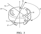
- the latch cap 24 comprises two straight grooves between them angle B of 150 degrees but can in other alternatives take any value for example between 120 degrees and 180 degrees.
- the cap 24 comprises two clips 27 extending downwards along a vertical axis Z.
- the two arms (28, 29) of the T-connector element 22 extend along two distinct arm axes (Y1, Y2) perpendicular to a body axis (Z) for the T-shaped connector 12.
- L T-connector element 22 comprises an elongated body 26 with four open-ended indentations 36 extending along the Z axis and two arms 28, 29 perpendicular to the body 26 extending along the Y axis.
- the body 26 is connected to the fuel injector 10 by the end 36 and comprises an internal channel for the flow of fuel to the hydraulic circuit 14.
- the two axes of the arms (Y1, Y2) make a generally constant angle ( C) with the main direction (X1), said angle (C) being generally equal to 90 ° - B / 2.
- the tubular cage 20 comprises a cylindrical wall and along the wall two lateral indentations 31 and protruding only at one end 32 so as to obtain an elasticity of the cylindrical wall of the cage 20 during the insertion of the connecting element 22.
- the arms 28, 29 comprise grooves and have an ogival shape at their ends.
- the arms 28 include an internal channel for the flow of fuel to the pipe elements 16.
- the body 26 is adapted to be connected to a fuel injector (not shown) and each arm 28 is adapted to be connected to the end of the fuel. a pipe element 16.
- the body 26 is arranged in the cage 20, each arm 28 extending through a notch 30.
- the connecting member 23 comprises a body 26 extending along the longitudinal axis Z and a single arm 28 perpendicular to the body 26 and extending along the axis Y1
- the L-shaped connector 13 is identical to the T-connector 12 with the exception of the connector element 23 comprising only one arm 28.
- the L-shaped connector 13 differs from the T-connector 12 by the connector element.
- L 23 which has only one arm 28 while the T-connector element 22 of the T-connector 12 comprises two arms 28, 29.
- the leakage return hydraulic circuit 14 is intended exclusively for direct diesel fuel injection equipment for an internal combustion engine. If the internal combustion engine comprises an "N" number of fuel injectors 10 then the leakage return hydraulic circuit 14 comprises "N" connectors T 12 and L 13 and "N-1" pipe elements 16.
- the connectors T 12, L 13 comprise "N-1" T-connectors 12 and an L-shaped connector 13.
- the embodiment of leakage return circuit 14 extends between a first L-shaped connector 13 and a T-shaped connector 12.
Landscapes
- Engineering & Computer Science (AREA)
- Mechanical Engineering (AREA)
- Chemical & Material Sciences (AREA)
- Combustion & Propulsion (AREA)
- General Engineering & Computer Science (AREA)
- Manufacturing & Machinery (AREA)
- Fuel-Injection Apparatus (AREA)
- Moulds For Moulding Plastics Or The Like (AREA)
- Injection Moulding Of Plastics Or The Like (AREA)
Claims (6)
- Verfahren zum Formen eines Hydraulikverbinders (12, 13) aus geformtem Kunststoff, wobei der Verbinder (12, 13) ausschließlich dazu vorgesehen ist, in einem Dieselkraftstoffrücklauf-Hydraulikkreis einer Direkteinspritzanlage für einen Verbrennungsmotor angeordnet zu werden, wobei der Verbinder (12, 13) entweder T-förmig (12) oder L-förmig (13) ist und wobei der Verbinder (12, 13) enthält:- ein Verbindungselement (22, 23), das einen insgesamt zylindrischen Körper (26) mit einer Körperachse (Z) und im Falle eines L-förmigen Verbinders (13) einen Arm (28), der sich entlang einer Armachse (Y1) erstreckt, die senkrecht zur Körperachse (Z) verläuft, und im Falle eines T-förmigen Verbinders (12) zwei Arme (28, 29) enthält, die sich entlang von zwei unterschiedlichen Armachsen (Y1, Y2) erstrecken, die senkrecht zur Körperachse (Z) verlaufen, wobei der Körper (26) dazu geeignet ist, mit einem Kraftstoffeinspritzventil (10) verbunden zu werden, und jeder Arm (28, 29) dazu geeignet ist, mit dem Ende eines Rohrstücks (16) verbunden zu werden, und- einen rohrförmigen zylindrischen Käfig (20), der sich entlang der Körperachse (Z) erstreckt, wobei der Käfig mit zwei seitlichen Aussparungen (30, 31) versehen ist, wobei der Körper (26) im Käfig (20) angeordnet ist, wobei jede Aussparung (30, 31) die Erstreckung eines Arms (28, 29) ermöglicht, und- eine Verriegelungskappe (24), die komplementär an einem Ende des rohrförmigen Käfigs (20) verriegelt ist, so dass sie das Verbindungselement (22, 23) im Käfig (20) einschließt,wobei das Formverfahren die folgenden Schritte umfasst:a) Bereitstellen einer Gießform mit einem T-förmigen Verbindungselementhohlraum (22), wobei der Hohlraum einen Körperhohlraum (26) und zwei Armhohlräume (28, 29) aufweist;b) Anordnen eines Einsatzes in den Hohlraum eines der beiden Arme (28, 29), wenn ein L-förmiges Verbindungselements (23) geformt werden soll.
- Formverfahren zum Formen eines Hydraulikverbinders (12) nach Anspruch 1,
wobei die Gießform eine Mehrfachform ist, bei der sämtliche Hohlräume identisch sind und jeweils einen Körperhohlraum (26) und zwei Armhohlräume (28) aufweisen. - Formverfahren zum Formen eines Hydraulikverbinders nach Anspruch 1 oder 2,
wobei die Armhohlräume (28) einen Winkel (B) miteinander einschließen, so dass die Arme (28) des Verbindungselements (22) den Winkel (B) miteinander einschließen, wobei der Winkel (B) sich in eine Ebene senkrecht zur Körperachse (Z) einschreibt. - Formverfahren zum Formen eines Hydraulikverbinders (12, 13) nach Anspruch 3,
wobei der Winkel (B) zwischen 120° und 180°, vorzugsweise etwa 150°, beträgt. - Verfahren zum Herstellen eines Rücklauf-Hydraulikkreislaufs (14), der ausschließlich für eine Dieselkraftstoff-Direkteinspritzanlage für einen Verbrennungsmotor vorgesehen ist, wobei der Kreislauf (14) sich zwischen einem L-förmigen ersten Verbinder (13) und einem T-förmigen letzten Verbinder (12) erstreckt und eine Mehrzahl von T-förmigen Zwischenverbindern (12) sowie eine Mehrzahl von Rohrstücken (16) enthält, wobei die Arme (28) sämtlicher Verbinder (12, 13) insgesamt in einer Hauptrichtung (X1) ausgerichtet sind und wobei ein Rohrstück (16) zwischen zwei benachbarten Verbindern (12, 13) angeordnet ist,
wobei das Verfahren dadurch gekennzeichnet ist, dass
sämtliche Verbinder (12, 13) nach einem der Ansprüche 3 oder 4 hergestellt und so angeordnet sind, dass die Armachsen (Y1, Y2) einen insgesamt konstanten Winkel (C) mit der Hauptrichtung (X1) einschließen, wobei der Winkel (C) insgesamt gleich 90° - B/2 ist, und
der am Ende des Kreislaufs (14) angeordnete T-förmige Verbinder (12) um die Körperachse (Z) um einen Winkel gedreht ist, der insgesamt gleich dem Zwischenarmwinkel (B) bezüglich der weiteren T-förmigen Verbinder (12) des Hydraulikkreislaufs ist. - Verfahren zum Herstellen eines Leckrücklauf-Hydraulikkreislaufes (14) nach Anspruch 5,
wobei die Rohrstücke (16) identische Längen aufweisen.
Applications Claiming Priority (2)
| Application Number | Priority Date | Filing Date | Title |
|---|---|---|---|
| FR1650958A FR3047434B1 (fr) | 2016-02-05 | 2016-02-05 | Connecteur de circuit de retour de fuite |
| PCT/EP2017/052288 WO2017134180A1 (fr) | 2016-02-05 | 2017-02-02 | Connecteur de circuit de retour de fuite |
Publications (2)
| Publication Number | Publication Date |
|---|---|
| EP3411209A1 EP3411209A1 (de) | 2018-12-12 |
| EP3411209B1 true EP3411209B1 (de) | 2019-12-04 |
Family
ID=56084168
Family Applications (1)
| Application Number | Title | Priority Date | Filing Date |
|---|---|---|---|
| EP17702138.3A Active EP3411209B1 (de) | 2016-02-05 | 2017-02-02 | Stecker für eine hydraulische rückflussleitung |
Country Status (5)
| Country | Link |
|---|---|
| US (1) | US10473074B2 (de) |
| EP (1) | EP3411209B1 (de) |
| CN (1) | CN109070394B (de) |
| FR (1) | FR3047434B1 (de) |
| WO (1) | WO2017134180A1 (de) |
Cited By (1)
| Publication number | Priority date | Publication date | Assignee | Title |
|---|---|---|---|---|
| US11542902B2 (en) * | 2018-07-26 | 2023-01-03 | Liebherr-Components Deggendorf Gmbh | Connecting piece for a fuel injector of an internal combustion engine |
Families Citing this family (1)
| Publication number | Priority date | Publication date | Assignee | Title |
|---|---|---|---|---|
| JP2020153337A (ja) * | 2019-03-22 | 2020-09-24 | ヤンマーパワーテクノロジー株式会社 | エンジン |
Family Cites Families (7)
| Publication number | Priority date | Publication date | Assignee | Title |
|---|---|---|---|---|
| DE10240130A1 (de) * | 2002-08-30 | 2004-03-18 | Robert Bosch Gmbh | Steckverbindung für medienführende Leitungen |
| DE10360336A1 (de) * | 2003-12-20 | 2005-07-14 | Robert Bosch Gmbh | Steckerelement mit Winkeladapter |
| JP4947083B2 (ja) * | 2009-03-31 | 2012-06-06 | 株式会社デンソー | インジェクタ用コネクタの製造方法 |
| JP2010236642A (ja) * | 2009-03-31 | 2010-10-21 | Denso Corp | コネクタ |
| JP5595457B2 (ja) * | 2012-09-05 | 2014-09-24 | 東海ゴム工業株式会社 | コネクタ |
| DE102013008302A1 (de) * | 2013-05-15 | 2014-11-20 | Braunform Gmbh | Werkzeug zum Spritzgießen von Kunststoffteilen |
| WO2015068867A1 (ko) * | 2013-11-06 | 2015-05-14 | 주식회사 니프코코리아 | 퀵 커넥터 장치 |
-
2016
- 2016-02-05 FR FR1650958A patent/FR3047434B1/fr not_active Expired - Fee Related
-
2017
- 2017-02-02 US US16/075,319 patent/US10473074B2/en not_active Expired - Fee Related
- 2017-02-02 EP EP17702138.3A patent/EP3411209B1/de active Active
- 2017-02-02 WO PCT/EP2017/052288 patent/WO2017134180A1/fr not_active Ceased
- 2017-02-02 CN CN201780022122.2A patent/CN109070394B/zh active Active
Non-Patent Citations (1)
| Title |
|---|
| None * |
Cited By (1)
| Publication number | Priority date | Publication date | Assignee | Title |
|---|---|---|---|---|
| US11542902B2 (en) * | 2018-07-26 | 2023-01-03 | Liebherr-Components Deggendorf Gmbh | Connecting piece for a fuel injector of an internal combustion engine |
Also Published As
| Publication number | Publication date |
|---|---|
| FR3047434B1 (fr) | 2018-09-07 |
| WO2017134180A1 (fr) | 2017-08-10 |
| FR3047434A1 (fr) | 2017-08-11 |
| EP3411209A1 (de) | 2018-12-12 |
| US20190040829A1 (en) | 2019-02-07 |
| CN109070394B (zh) | 2020-12-18 |
| US10473074B2 (en) | 2019-11-12 |
| CN109070394A (zh) | 2018-12-21 |
Similar Documents
| Publication | Publication Date | Title |
|---|---|---|
| US8991637B2 (en) | Molded reservoir support structure coupling | |
| EP2789824B1 (de) | Kühlvorrichtung mit geringem Platzbedarf für Verbrennungsmotor, und Herstellungsverfahren einer solchen Vorrichtung | |
| WO2017134180A1 (fr) | Connecteur de circuit de retour de fuite | |
| FR3025047B1 (fr) | Reservoir d'alimentation en eau de refroidissement ayant une fonction de prevention de melange thermique et systeme passif d'injection de securite a haute pression et procede utilisant ce dernier | |
| FR3080166A1 (fr) | Rampe distributrice-collectrice de fluide | |
| FR2950396A1 (fr) | Module fonctionnel integrant un repartiteur et une rampe d'injection et son procede de fabrication | |
| CN107850002B (zh) | 进气端口用嵌件的模具组件 | |
| FR2726625A1 (fr) | Dispositif de mise en forme d'un conduit en matiere plastique ou en matiere elastiquement deformable | |
| FR2860557A1 (fr) | Injecteur de carburant de moteur a combustion interne pour vehicule comprenant une buse presentant au moins un orifice | |
| WO2018036966A1 (fr) | Corps de buse d'injecteur de carburant | |
| FR2753495A1 (fr) | Ventilateur, en particulier pour appareil de refroidissement et/ou chauffage et/ou climatisation de vehicule automobile | |
| FR2664673A1 (fr) | Raccord de jonction a piece d'insertion et revetement. | |
| WO2019234080A1 (fr) | Outillage de surmoulage modulaire de toron de cables et procédé de gainage utilisant un tel outillage | |
| DE102017207303A1 (de) | Verteilervorrichtung für eine Einspritzvorrichtung einer Brennkraftmaschine | |
| FR2778961A1 (fr) | Collier de maintien pour au moins deux elements allonges | |
| JP5465222B2 (ja) | 燃料輸送用のコネクタ付樹脂チューブの製造方法 | |
| FR2978230A1 (fr) | Dispositif d'indexage angulaire multi-positions pour le raccordement de deux embouts | |
| JP2006170384A (ja) | 燃料輸送用の樹脂チューブ及びその製造方法 | |
| EP4004442B1 (de) | Kraftstoffinjektor mit einem spülkreis für ein flugzeugtriebwerk | |
| EP3898305A1 (de) | Wärmesystem für ein kraftfahrzeug | |
| EP4025499B1 (de) | Klimaanlage mit integriertem wasserextraktionskreis | |
| EP3649402A1 (de) | Brennkammermodul für ein flugzeugtriebwerk mit markierungen zur erleichterung der identifizierung während einer endoskopischen inspektion der brennkammer | |
| FR2977848A1 (fr) | Adaptateur de conduite de liquide et dispositif de distribution de liquide de balais d'essuie-glace de vehicule automobile | |
| FR3090507A1 (fr) | Système thermique d’un véhicule automobile | |
| KR101722253B1 (ko) | 오일스크린 장착파이프 |
Legal Events
| Date | Code | Title | Description |
|---|---|---|---|
| STAA | Information on the status of an ep patent application or granted ep patent |
Free format text: STATUS: UNKNOWN |
|
| STAA | Information on the status of an ep patent application or granted ep patent |
Free format text: STATUS: THE INTERNATIONAL PUBLICATION HAS BEEN MADE |
|
| PUAI | Public reference made under article 153(3) epc to a published international application that has entered the european phase |
Free format text: ORIGINAL CODE: 0009012 |
|
| STAA | Information on the status of an ep patent application or granted ep patent |
Free format text: STATUS: REQUEST FOR EXAMINATION WAS MADE |
|
| 17P | Request for examination filed |
Effective date: 20180905 |
|
| AK | Designated contracting states |
Kind code of ref document: A1 Designated state(s): AL AT BE BG CH CY CZ DE DK EE ES FI FR GB GR HR HU IE IS IT LI LT LU LV MC MK MT NL NO PL PT RO RS SE SI SK SM TR |
|
| AX | Request for extension of the european patent |
Extension state: BA ME |
|
| DAV | Request for validation of the european patent (deleted) | ||
| DAX | Request for extension of the european patent (deleted) | ||
| GRAP | Despatch of communication of intention to grant a patent |
Free format text: ORIGINAL CODE: EPIDOSNIGR1 |
|
| STAA | Information on the status of an ep patent application or granted ep patent |
Free format text: STATUS: GRANT OF PATENT IS INTENDED |
|
| INTG | Intention to grant announced |
Effective date: 20190711 |
|
| GRAS | Grant fee paid |
Free format text: ORIGINAL CODE: EPIDOSNIGR3 |
|
| GRAA | (expected) grant |
Free format text: ORIGINAL CODE: 0009210 |
|
| STAA | Information on the status of an ep patent application or granted ep patent |
Free format text: STATUS: THE PATENT HAS BEEN GRANTED |
|
| AK | Designated contracting states |
Kind code of ref document: B1 Designated state(s): AL AT BE BG CH CY CZ DE DK EE ES FI FR GB GR HR HU IE IS IT LI LT LU LV MC MK MT NL NO PL PT RO RS SE SI SK SM TR |
|
| REG | Reference to a national code |
Ref country code: GB Ref legal event code: FG4D Free format text: NOT ENGLISH |
|
| REG | Reference to a national code |
Ref country code: CH Ref legal event code: EP |
|
| REG | Reference to a national code |
Ref country code: AT Ref legal event code: REF Ref document number: 1208821 Country of ref document: AT Kind code of ref document: T Effective date: 20191215 |
|
| REG | Reference to a national code |
Ref country code: DE Ref legal event code: R096 Ref document number: 602017009365 Country of ref document: DE |
|
| REG | Reference to a national code |
Ref country code: IE Ref legal event code: FG4D Free format text: LANGUAGE OF EP DOCUMENT: FRENCH |
|
| REG | Reference to a national code |
Ref country code: NL Ref legal event code: MP Effective date: 20191204 |
|
| REG | Reference to a national code |
Ref country code: LT Ref legal event code: MG4D |
|
| PG25 | Lapsed in a contracting state [announced via postgrant information from national office to epo] |
Ref country code: SE Free format text: LAPSE BECAUSE OF FAILURE TO SUBMIT A TRANSLATION OF THE DESCRIPTION OR TO PAY THE FEE WITHIN THE PRESCRIBED TIME-LIMIT Effective date: 20191204 Ref country code: LV Free format text: LAPSE BECAUSE OF FAILURE TO SUBMIT A TRANSLATION OF THE DESCRIPTION OR TO PAY THE FEE WITHIN THE PRESCRIBED TIME-LIMIT Effective date: 20191204 Ref country code: LT Free format text: LAPSE BECAUSE OF FAILURE TO SUBMIT A TRANSLATION OF THE DESCRIPTION OR TO PAY THE FEE WITHIN THE PRESCRIBED TIME-LIMIT Effective date: 20191204 Ref country code: GR Free format text: LAPSE BECAUSE OF FAILURE TO SUBMIT A TRANSLATION OF THE DESCRIPTION OR TO PAY THE FEE WITHIN THE PRESCRIBED TIME-LIMIT Effective date: 20200305 Ref country code: NO Free format text: LAPSE BECAUSE OF FAILURE TO SUBMIT A TRANSLATION OF THE DESCRIPTION OR TO PAY THE FEE WITHIN THE PRESCRIBED TIME-LIMIT Effective date: 20200304 Ref country code: BG Free format text: LAPSE BECAUSE OF FAILURE TO SUBMIT A TRANSLATION OF THE DESCRIPTION OR TO PAY THE FEE WITHIN THE PRESCRIBED TIME-LIMIT Effective date: 20200304 Ref country code: FI Free format text: LAPSE BECAUSE OF FAILURE TO SUBMIT A TRANSLATION OF THE DESCRIPTION OR TO PAY THE FEE WITHIN THE PRESCRIBED TIME-LIMIT Effective date: 20191204 |
|
| PG25 | Lapsed in a contracting state [announced via postgrant information from national office to epo] |
Ref country code: RS Free format text: LAPSE BECAUSE OF FAILURE TO SUBMIT A TRANSLATION OF THE DESCRIPTION OR TO PAY THE FEE WITHIN THE PRESCRIBED TIME-LIMIT Effective date: 20191204 Ref country code: HR Free format text: LAPSE BECAUSE OF FAILURE TO SUBMIT A TRANSLATION OF THE DESCRIPTION OR TO PAY THE FEE WITHIN THE PRESCRIBED TIME-LIMIT Effective date: 20191204 |
|
| PG25 | Lapsed in a contracting state [announced via postgrant information from national office to epo] |
Ref country code: AL Free format text: LAPSE BECAUSE OF FAILURE TO SUBMIT A TRANSLATION OF THE DESCRIPTION OR TO PAY THE FEE WITHIN THE PRESCRIBED TIME-LIMIT Effective date: 20191204 |
|
| PG25 | Lapsed in a contracting state [announced via postgrant information from national office to epo] |
Ref country code: RO Free format text: LAPSE BECAUSE OF FAILURE TO SUBMIT A TRANSLATION OF THE DESCRIPTION OR TO PAY THE FEE WITHIN THE PRESCRIBED TIME-LIMIT Effective date: 20191204 Ref country code: CZ Free format text: LAPSE BECAUSE OF FAILURE TO SUBMIT A TRANSLATION OF THE DESCRIPTION OR TO PAY THE FEE WITHIN THE PRESCRIBED TIME-LIMIT Effective date: 20191204 Ref country code: PT Free format text: LAPSE BECAUSE OF FAILURE TO SUBMIT A TRANSLATION OF THE DESCRIPTION OR TO PAY THE FEE WITHIN THE PRESCRIBED TIME-LIMIT Effective date: 20200429 Ref country code: NL Free format text: LAPSE BECAUSE OF FAILURE TO SUBMIT A TRANSLATION OF THE DESCRIPTION OR TO PAY THE FEE WITHIN THE PRESCRIBED TIME-LIMIT Effective date: 20191204 Ref country code: ES Free format text: LAPSE BECAUSE OF FAILURE TO SUBMIT A TRANSLATION OF THE DESCRIPTION OR TO PAY THE FEE WITHIN THE PRESCRIBED TIME-LIMIT Effective date: 20191204 Ref country code: EE Free format text: LAPSE BECAUSE OF FAILURE TO SUBMIT A TRANSLATION OF THE DESCRIPTION OR TO PAY THE FEE WITHIN THE PRESCRIBED TIME-LIMIT Effective date: 20191204 |
|
| PG25 | Lapsed in a contracting state [announced via postgrant information from national office to epo] |
Ref country code: IS Free format text: LAPSE BECAUSE OF FAILURE TO SUBMIT A TRANSLATION OF THE DESCRIPTION OR TO PAY THE FEE WITHIN THE PRESCRIBED TIME-LIMIT Effective date: 20200404 Ref country code: SK Free format text: LAPSE BECAUSE OF FAILURE TO SUBMIT A TRANSLATION OF THE DESCRIPTION OR TO PAY THE FEE WITHIN THE PRESCRIBED TIME-LIMIT Effective date: 20191204 Ref country code: SM Free format text: LAPSE BECAUSE OF FAILURE TO SUBMIT A TRANSLATION OF THE DESCRIPTION OR TO PAY THE FEE WITHIN THE PRESCRIBED TIME-LIMIT Effective date: 20191204 |
|
| REG | Reference to a national code |
Ref country code: DE Ref legal event code: R097 Ref document number: 602017009365 Country of ref document: DE |
|
| REG | Reference to a national code |
Ref country code: AT Ref legal event code: MK05 Ref document number: 1208821 Country of ref document: AT Kind code of ref document: T Effective date: 20191204 |
|
| REG | Reference to a national code |
Ref country code: CH Ref legal event code: PL |
|
| PLBE | No opposition filed within time limit |
Free format text: ORIGINAL CODE: 0009261 |
|
| STAA | Information on the status of an ep patent application or granted ep patent |
Free format text: STATUS: NO OPPOSITION FILED WITHIN TIME LIMIT |
|
| REG | Reference to a national code |
Ref country code: BE Ref legal event code: MM Effective date: 20200229 |
|
| PG25 | Lapsed in a contracting state [announced via postgrant information from national office to epo] |
Ref country code: MC Free format text: LAPSE BECAUSE OF FAILURE TO SUBMIT A TRANSLATION OF THE DESCRIPTION OR TO PAY THE FEE WITHIN THE PRESCRIBED TIME-LIMIT Effective date: 20191204 Ref country code: LU Free format text: LAPSE BECAUSE OF NON-PAYMENT OF DUE FEES Effective date: 20200202 Ref country code: DK Free format text: LAPSE BECAUSE OF FAILURE TO SUBMIT A TRANSLATION OF THE DESCRIPTION OR TO PAY THE FEE WITHIN THE PRESCRIBED TIME-LIMIT Effective date: 20191204 |
|
| 26N | No opposition filed |
Effective date: 20200907 |
|
| PG25 | Lapsed in a contracting state [announced via postgrant information from national office to epo] |
Ref country code: SI Free format text: LAPSE BECAUSE OF FAILURE TO SUBMIT A TRANSLATION OF THE DESCRIPTION OR TO PAY THE FEE WITHIN THE PRESCRIBED TIME-LIMIT Effective date: 20191204 Ref country code: PL Free format text: LAPSE BECAUSE OF FAILURE TO SUBMIT A TRANSLATION OF THE DESCRIPTION OR TO PAY THE FEE WITHIN THE PRESCRIBED TIME-LIMIT Effective date: 20191204 Ref country code: AT Free format text: LAPSE BECAUSE OF FAILURE TO SUBMIT A TRANSLATION OF THE DESCRIPTION OR TO PAY THE FEE WITHIN THE PRESCRIBED TIME-LIMIT Effective date: 20191204 Ref country code: LI Free format text: LAPSE BECAUSE OF NON-PAYMENT OF DUE FEES Effective date: 20200229 Ref country code: CH Free format text: LAPSE BECAUSE OF NON-PAYMENT OF DUE FEES Effective date: 20200229 |
|
| PG25 | Lapsed in a contracting state [announced via postgrant information from national office to epo] |
Ref country code: IE Free format text: LAPSE BECAUSE OF NON-PAYMENT OF DUE FEES Effective date: 20200202 Ref country code: IT Free format text: LAPSE BECAUSE OF FAILURE TO SUBMIT A TRANSLATION OF THE DESCRIPTION OR TO PAY THE FEE WITHIN THE PRESCRIBED TIME-LIMIT Effective date: 20191204 |
|
| PG25 | Lapsed in a contracting state [announced via postgrant information from national office to epo] |
Ref country code: BE Free format text: LAPSE BECAUSE OF NON-PAYMENT OF DUE FEES Effective date: 20200229 |
|
| PGFP | Annual fee paid to national office [announced via postgrant information from national office to epo] |
Ref country code: FR Payment date: 20210223 Year of fee payment: 5 |
|
| PGFP | Annual fee paid to national office [announced via postgrant information from national office to epo] |
Ref country code: GB Payment date: 20210225 Year of fee payment: 5 |
|
| PG25 | Lapsed in a contracting state [announced via postgrant information from national office to epo] |
Ref country code: TR Free format text: LAPSE BECAUSE OF FAILURE TO SUBMIT A TRANSLATION OF THE DESCRIPTION OR TO PAY THE FEE WITHIN THE PRESCRIBED TIME-LIMIT Effective date: 20191204 Ref country code: MT Free format text: LAPSE BECAUSE OF FAILURE TO SUBMIT A TRANSLATION OF THE DESCRIPTION OR TO PAY THE FEE WITHIN THE PRESCRIBED TIME-LIMIT Effective date: 20191204 Ref country code: CY Free format text: LAPSE BECAUSE OF FAILURE TO SUBMIT A TRANSLATION OF THE DESCRIPTION OR TO PAY THE FEE WITHIN THE PRESCRIBED TIME-LIMIT Effective date: 20191204 |
|
| PG25 | Lapsed in a contracting state [announced via postgrant information from national office to epo] |
Ref country code: MK Free format text: LAPSE BECAUSE OF FAILURE TO SUBMIT A TRANSLATION OF THE DESCRIPTION OR TO PAY THE FEE WITHIN THE PRESCRIBED TIME-LIMIT Effective date: 20191204 |
|
| GBPC | Gb: european patent ceased through non-payment of renewal fee |
Effective date: 20220202 |
|
| PG25 | Lapsed in a contracting state [announced via postgrant information from national office to epo] |
Ref country code: FR Free format text: LAPSE BECAUSE OF NON-PAYMENT OF DUE FEES Effective date: 20220228 |
|
| PG25 | Lapsed in a contracting state [announced via postgrant information from national office to epo] |
Ref country code: GB Free format text: LAPSE BECAUSE OF NON-PAYMENT OF DUE FEES Effective date: 20220202 |
|
| P01 | Opt-out of the competence of the unified patent court (upc) registered |
Effective date: 20230327 |
|
| REG | Reference to a national code |
Ref country code: DE Ref legal event code: R081 Ref document number: 602017009365 Country of ref document: DE Owner name: PHINIA DELPHI LUXEMBOURG SARL, LU Free format text: FORMER OWNER: DELPHI TECHNOLOGIES IP LIMITED, ST. MICHAEL, BB |
|
| PGFP | Annual fee paid to national office [announced via postgrant information from national office to epo] |
Ref country code: DE Payment date: 20260115 Year of fee payment: 10 |