EP3411593B1 - Windturbine, deren verwendung und schaufel zur verwendung in der turbine - Google Patents
Windturbine, deren verwendung und schaufel zur verwendung in der turbine Download PDFInfo
- Publication number
- EP3411593B1 EP3411593B1 EP17705039.0A EP17705039A EP3411593B1 EP 3411593 B1 EP3411593 B1 EP 3411593B1 EP 17705039 A EP17705039 A EP 17705039A EP 3411593 B1 EP3411593 B1 EP 3411593B1
- Authority
- EP
- European Patent Office
- Prior art keywords
- vane
- wind
- lid
- receptacle
- wind turbine
- Prior art date
- Legal status (The legal status is an assumption and is not a legal conclusion. Google has not performed a legal analysis and makes no representation as to the accuracy of the status listed.)
- Active
Links
- 238000006243 chemical reaction Methods 0.000 description 21
- 230000033001 locomotion Effects 0.000 description 8
- 230000005484 gravity Effects 0.000 description 5
- 238000007664 blowing Methods 0.000 description 3
- 230000000694 effects Effects 0.000 description 3
- 238000011144 upstream manufacturing Methods 0.000 description 3
- 238000010276 construction Methods 0.000 description 2
- 238000011161 development Methods 0.000 description 2
- 230000018109 developmental process Effects 0.000 description 2
- 230000008092 positive effect Effects 0.000 description 2
- XLYOFNOQVPJJNP-UHFFFAOYSA-N water Substances O XLYOFNOQVPJJNP-UHFFFAOYSA-N 0.000 description 2
- 238000003491 array Methods 0.000 description 1
- 230000000052 comparative effect Effects 0.000 description 1
- 230000007423 decrease Effects 0.000 description 1
- 230000003247 decreasing effect Effects 0.000 description 1
- 230000003292 diminished effect Effects 0.000 description 1
- 230000009977 dual effect Effects 0.000 description 1
- 230000005611 electricity Effects 0.000 description 1
- 239000012530 fluid Substances 0.000 description 1
- 239000000411 inducer Substances 0.000 description 1
- 230000002452 interceptive effect Effects 0.000 description 1
- 238000005086 pumping Methods 0.000 description 1
- 238000001228 spectrum Methods 0.000 description 1
Images


Classifications
-
- F—MECHANICAL ENGINEERING; LIGHTING; HEATING; WEAPONS; BLASTING
- F03—MACHINES OR ENGINES FOR LIQUIDS; WIND, SPRING, OR WEIGHT MOTORS; PRODUCING MECHANICAL POWER OR A REACTIVE PROPULSIVE THRUST, NOT OTHERWISE PROVIDED FOR
- F03D—WIND MOTORS
- F03D3/00—Wind motors with rotation axis substantially perpendicular to the air flow entering the rotor
- F03D3/005—Wind motors with rotation axis substantially perpendicular to the air flow entering the rotor the axis being vertical
-
- F—MECHANICAL ENGINEERING; LIGHTING; HEATING; WEAPONS; BLASTING
- F03—MACHINES OR ENGINES FOR LIQUIDS; WIND, SPRING, OR WEIGHT MOTORS; PRODUCING MECHANICAL POWER OR A REACTIVE PROPULSIVE THRUST, NOT OTHERWISE PROVIDED FOR
- F03D—WIND MOTORS
- F03D3/00—Wind motors with rotation axis substantially perpendicular to the air flow entering the rotor
- F03D3/06—Rotors
- F03D3/061—Rotors characterised by their aerodynamic shape, e.g. aerofoil profiles
-
- F—MECHANICAL ENGINEERING; LIGHTING; HEATING; WEAPONS; BLASTING
- F03—MACHINES OR ENGINES FOR LIQUIDS; WIND, SPRING, OR WEIGHT MOTORS; PRODUCING MECHANICAL POWER OR A REACTIVE PROPULSIVE THRUST, NOT OTHERWISE PROVIDED FOR
- F03D—WIND MOTORS
- F03D3/00—Wind motors with rotation axis substantially perpendicular to the air flow entering the rotor
- F03D3/06—Rotors
- F03D3/062—Rotors characterised by their construction elements
-
- F—MECHANICAL ENGINEERING; LIGHTING; HEATING; WEAPONS; BLASTING
- F05—INDEXING SCHEMES RELATING TO ENGINES OR PUMPS IN VARIOUS SUBCLASSES OF CLASSES F01-F04
- F05B—INDEXING SCHEME RELATING TO WIND, SPRING, WEIGHT, INERTIA OR LIKE MOTORS, TO MACHINES OR ENGINES FOR LIQUIDS COVERED BY SUBCLASSES F03B, F03D AND F03G
- F05B2240/00—Components
- F05B2240/20—Rotors
- F05B2240/21—Rotors for wind turbines
- F05B2240/211—Rotors for wind turbines with vertical axis
-
- F—MECHANICAL ENGINEERING; LIGHTING; HEATING; WEAPONS; BLASTING
- F05—INDEXING SCHEMES RELATING TO ENGINES OR PUMPS IN VARIOUS SUBCLASSES OF CLASSES F01-F04
- F05B—INDEXING SCHEME RELATING TO WIND, SPRING, WEIGHT, INERTIA OR LIKE MOTORS, TO MACHINES OR ENGINES FOR LIQUIDS COVERED BY SUBCLASSES F03B, F03D AND F03G
- F05B2240/00—Components
- F05B2240/20—Rotors
- F05B2240/21—Rotors for wind turbines
- F05B2240/211—Rotors for wind turbines with vertical axis
- F05B2240/218—Rotors for wind turbines with vertical axis with horizontally hinged vanes
-
- F—MECHANICAL ENGINEERING; LIGHTING; HEATING; WEAPONS; BLASTING
- F05—INDEXING SCHEMES RELATING TO ENGINES OR PUMPS IN VARIOUS SUBCLASSES OF CLASSES F01-F04
- F05B—INDEXING SCHEME RELATING TO WIND, SPRING, WEIGHT, INERTIA OR LIKE MOTORS, TO MACHINES OR ENGINES FOR LIQUIDS COVERED BY SUBCLASSES F03B, F03D AND F03G
- F05B2240/00—Components
- F05B2240/20—Rotors
- F05B2240/21—Rotors for wind turbines
- F05B2240/231—Rotors for wind turbines driven by aerodynamic lift effects
-
- F—MECHANICAL ENGINEERING; LIGHTING; HEATING; WEAPONS; BLASTING
- F05—INDEXING SCHEMES RELATING TO ENGINES OR PUMPS IN VARIOUS SUBCLASSES OF CLASSES F01-F04
- F05B—INDEXING SCHEME RELATING TO WIND, SPRING, WEIGHT, INERTIA OR LIKE MOTORS, TO MACHINES OR ENGINES FOR LIQUIDS COVERED BY SUBCLASSES F03B, F03D AND F03G
- F05B2240/00—Components
- F05B2240/20—Rotors
- F05B2240/21—Rotors for wind turbines
- F05B2240/231—Rotors for wind turbines driven by aerodynamic lift effects
- F05B2240/232—Rotors for wind turbines driven by aerodynamic lift effects driven by drag
-
- F—MECHANICAL ENGINEERING; LIGHTING; HEATING; WEAPONS; BLASTING
- F05—INDEXING SCHEMES RELATING TO ENGINES OR PUMPS IN VARIOUS SUBCLASSES OF CLASSES F01-F04
- F05B—INDEXING SCHEME RELATING TO WIND, SPRING, WEIGHT, INERTIA OR LIKE MOTORS, TO MACHINES OR ENGINES FOR LIQUIDS COVERED BY SUBCLASSES F03B, F03D AND F03G
- F05B2240/00—Components
- F05B2240/20—Rotors
- F05B2240/30—Characteristics of rotor blades, i.e. of any element transforming dynamic fluid energy to or from rotational energy and being attached to a rotor
- F05B2240/302—Segmented or sectional blades
-
- Y—GENERAL TAGGING OF NEW TECHNOLOGICAL DEVELOPMENTS; GENERAL TAGGING OF CROSS-SECTIONAL TECHNOLOGIES SPANNING OVER SEVERAL SECTIONS OF THE IPC; TECHNICAL SUBJECTS COVERED BY FORMER USPC CROSS-REFERENCE ART COLLECTIONS [XRACs] AND DIGESTS
- Y02—TECHNOLOGIES OR APPLICATIONS FOR MITIGATION OR ADAPTATION AGAINST CLIMATE CHANGE
- Y02E—REDUCTION OF GREENHOUSE GAS [GHG] EMISSIONS, RELATED TO ENERGY GENERATION, TRANSMISSION OR DISTRIBUTION
- Y02E10/00—Energy generation through renewable energy sources
- Y02E10/70—Wind energy
- Y02E10/74—Wind turbines with rotation axis perpendicular to the wind direction
Definitions
- the present invention pertains to a wind turbine for converting wind into mechanical energy, comprising a support and a vane rotatively connected to said support, the vane comprising an elongated body and a wind receptacle which in essence is formed is a lid which is able to hinge with respect to the body such that the receptacle can adopt an open configuration wherein the lid is hinged away from the body, and a closed configuration wherein the lid is hinged towards the body, the lid having an outer surface which is the surface that is directed away from the wind when the receptacle takes the open configuration, and an opposite inner surface
- the invention pertains to a wind turbine wherein the inner surface of the lid is provided with one or more profiles protruding from the inner surface, and extending in a direction perpendicular to the longitudinal direction of the vane.
- the invention also pertains to the use of the wind turbine for converting wind into work, and to a vane for use in the wind turbine.
- Wind turbines are commonly used since centuries to convert wind into work.
- a wind turbine typically is an impulse turbine.
- the turbine changes the direction of flow of the wind and the resulting impulse spins the turbine and leaves the wind with diminished kinetic energy.
- the device may be called a wind generator or wind charger.
- the mechanical energy is used to drive machinery, such as for grinding grain or pumping water, the device is usually called a windmill or wind pump.
- today's wind turbines are manufactured in a range of vertical and horizontal axle types. The most common and oldest ones are the horizontal axle turbines, wherein the axles are positioned in line with the direction of the wind (i.e. the direction in which the wind blows).
- the smallest turbines are used for applications such as battery charging or auxiliary power on sailing boats, while large grid-connected arrays of turbines are becoming an increasingly large source of commercial electric power.
- axles are positioned transverse to the wind (as opposed to "in line” with the wind) which has the additional advantage that the vanes do not need to be pointed to the wind.
- the axles are positioned vertically (which explains the commonly used acronym VAWT: v ertical a xle w ind t urbine), but they may also be positioned horizontally as long as the axle is transverse to the wind (TAWT - t ransverse a xle w ind t urbine- would thus be a more correct acronym), typically substantially perpendicular to the direction in which the wind blows.
- VAWT v ertical a xle w ind t urbine
- a wind turbine as described in the preamble is known, apart from the one or more profiles on the inner surface of the lid.
- the vanes of this turbine are provided with multiple separate wind receptacles and means operable to force the receptacles to adopt either an open or a closed configuration independent from the direction of the wind.
- Advantages of this known wind turbine are that the energy conversion is considerable higher than with more conventional wind turbines, in particular at low wind speeds.
- the receptacles may be forced to actively take a configuration against the forces of gravity and/or wind, makes that the turbine requires only a very low wind velocity to start turning around.
- the turbine allows to achieve a very high maximum conversion of wind force into motion.
- US 5,570,997 discloses a wind turbine having a vane provided with a wind receptacle that opens when the vane is traveling in the direction of the wind and closes when the vane is traveling against the direction of the wind. This way, maximum capacity of the wind receptacle is used when the wind force has to be converted into motion of the vane, while the receptacle hardly counteracts this conversion when the vane travels against the direction of the wind.
- the receptacle opens by action of the wind blowing over the vane and closes under gravity when this wind action decreases.
- a wind turbine according to the preamble has been devised in which turbine the inner surface of the lid is provided with one or more profiles protruding from the inner surface, and extending (exclusively) in a direction perpendicular to the longitudinal direction of the vane, wherein the turbine is further improved by the one or more profiles diverging (in height and/or width) toward the site where the lid is hinged to the body.
- the wind can freely flow over the inner surface of the lid along the one or more profiles without being hindered in the direction perpendicular to the longitudinal direction of the vane, but the wind is hindered in its free flowing over the inner surface of the lid in the direction parallel to the longitudinal direction of the vane.
- Applicant found that by providing the inner surface of the lid with such profiles, i.e. by having profiles that extend across the surface of the lid, and that extend in a direction perpendicular to the longitudinal direction of the vane (in other words, none of the profiles present across the inner surface of the vane extend in the longitudinal direction of the vane), the energy conversion of the turbine as known in particular from WO2014/006075 can be improved with about 10-25% or above.
- a profile according to the invention has a dual positive effect. At first it is believed that it may serve to help in hinging the lid away from the body of the vane when the vane is approaching the position in which it is traveling fully in the direction of the wind, i.e. the position when extending perpendicular to the direction of the wind. By having the wind blowing laterally against the profile when the vane is still extending for the bigger part in the direction of the wind, this may help in forcing the lid to hinge away from the body of the vane. This way, the positive addition to the energy conversion by having the lid in the hinged away position (the receptacle than being in the open, wind catching position), is arrived at earlier in time.
- US 2008217925 like WO2012/041961 , also shows true bucket shaped wind receptacles.
- the bucket causes so much turbulence that energy conversion is negatively influenced.
- the profiles extend from the inner surface, that is, run across this surface, instead of laterally closing it by forming walls on the edges.
- the advantage of the present invention is that the energy conversion might be significantly improved, even at low wind speeds, by using mere profiles.
- Such profiles have the advantage that they are passive devices, like a turbulator or roughness element, that are steady and require no energy by definition.
- Active control elements, such as valves, require actuators and thus energy.
- the present invention also pertains to the use of a wind turbine as defined here-above for converting wind into work. As known from WO2014/006075 , the presently improved turbine might be advantageously combined with a Darrieus wind mill. The present invention also pertains to a vane provided with a receptacle as defined here-above.
- a wind turbine according to the present invention can be operatively connected to a ground plane, typically having a support (such as a rotating or stationary axle) extending in a vertical direction, but may also be placed with its support extending in a horizontal direction (as long as the axis of rotation of the vane extends transverse to the wind) for example by mounting the support against a vertically extending wall.
- the turbine can for example be placed on a floating raft or be placed on a pole that extends above water level.
- a surface that is directed away from the wind is a surface that faces the direction to which the wind blows, as opposed to a surface that is directed towards the winds which is a surface that is faced to the direction out of which the wind blows.
- An element extending in a direction means that the element in essence runs parallel to the said direction, diverting at most under an angle of 30° to that direction over its entire length, preferably diverting less than 29, 28, 27, 26, 25, 24, 23, 22, 21, 20, 19, 18, 17, 16, 15, 14, 13, 12, 11 or even less than 10° to the said direction.
- a profile that protrudes from a surface in the sense of the present invention has a macroscopic height of at least 2 millimetres.
- a vane is a usually relatively thin, rigid and flat element that when mounted along an axis is turned by a gas or fluid flowing across the vane.
- Typical examples are a blade in a turbine or a sail on a windmill.
- the configuration of an object is the form determined of the arrangement the parts of the object in relation to each other and in space.
- the direction of the wind is the main direction in which the wind blows.
- a wind receptacle is an element that may extend in a direction perpendicular to the direction of the wind in order to convert the force of the wind into a motion in the direction of the wind.
- a vane that travels in essence in the direction of the wind means that the vane is positively converting the force of the wind into motion (forward travel).
- a vane that travels in essence against the direction of the wind means that energy is needed to force the vane to travel back through the wind (backwards travel)
- the one or more profiles are cone-shaped, diverging towards the site where the lid is hinged to the body.
- the one or more profiles have a maximum height relative to the inner surface of the lid that is equal to at least 1% of the length of the lid in the longitudinal direction of the vane. It appears that at least the maximum height should meet a minimum value in order to arrive at an improvement in energy conversion that outweighs the additional costs of producing the turbine by adding the profiles(s).
- the maximum height is typically not the height that is adapted over the full length of the profile. Near the tip (upstream end) of the lid, i.e. the site furthest away from the site at which the lid hinges to the body of the vane, the height might even be close to or equal to zero to make sure the lid can hinge fully towards the body of the vane.
- the height of the profile may be at maximum without interfering with the closure of the lid.
- the height relative to the inner surface of the lid that is equal to at least 2, 3, 4, 5, 6, 7, 8 or even 9% of the length of the lid in the longitudinal direction of the vane.
- the one or more profiles have a maximum height relative to the inner surface of the lid that is equal to at least 10% of the length of the lid in the longitudinal direction of the vane.
- the vane is an aerofoil shaped body, the lid being hinged to the body at a position adjacent a downstream end of the said body.
- the vane comprises multiple receptacles. It was recognised that when using multiple receptacles, the freedom to operate the turbine to increase the energy conversion can be further improved. More importantly however, it was recognised that having multiple receptacles allows the use of vanes of a significant longer length than when using one (large) receptacle that extends over a corresponding length of the vane. At high rotational speeds namely, the forces generated on the vane near the tip of the vane are significantly larger than the forces generated on the vane near the support.
- the vane comprises a first receptacle at a top site of the vane and a second receptacle at a bottom side of the vane. In this embodiment near optimal use can be made of the receptacles and their capacity to convert wind energy into motion.
- the vane comprises multiple separate receptacles positioned along the length of the vane. It was recognised that the hydrodynamics (the flow of the air) along the length of the vane changes considerably when traveling from a position near the support (adjacent the heart of the turbine) to the tip of the vane.
- receptacles may have different configurations along the length of the vane accommodated to the differences in hydrodynamics.
- a receptacle positioned near the support has a larger cross-section than a receptacle positioned further away from the support. This way, change in absolute traveling speed of the different portions along the length of the vane can be accommodated to.
- each of the multiple separate receptacles comprises one or more profiles as defined herein above.
- the invention is embodied in a wind turbine that is provided with a means operable to force the receptacle to adopt the closed configuration when the vane travels against the direction of the wind.
- a means operable to force the receptacle to adopt the closed configuration when the vane travels against the direction of the wind Using the present invention, no means need to be present to force the receptacle to take the open configuration when the vane travels in the direction of the wind. Due to the presence of the profile(s) the energy conversion rate is significantly improved anyway, possible by the easier and earlier opening of the receptacle. Still, it is advantageous to have a forced closure of the receptacle to minimize energy conversion loss.
- the means that are operable to force the receptacle to adopt the configuration can have various embodiments as will be appreciated by any person having skill in the art of mechanics.
- the means could be constituted using mere mechanical parts such as levers, bars and sprockets, camshafts, rails and followers, optionally using hydraulics, or could be constituted using electromechanical parts such as (electro-)magnets, inducers, coils etc.
- electromechanical parts such as (electro-)magnets, inducers, coils etc.
- Various other constitutions somewhere in the spectrum (or even outside) between pure mechanical and pure electrical are of course usable.
- the invention is embodied in a wind turbine that is provided with a means operable to force the receptacle to adopt the closed configuration when the vane travels in the direction of the wind.
- the vane can for example be closed when the wind blows at a too high speed, in order to prevent that the turbine will rotate too fast.
- Example 1 provides data regarding energy conversion using a wind turbine according to the invention
- Figure 1 shows a wind turbine as known from WO2014/006075 .
- the turbine comprises two vanes 6 and 16 that are part of a rotor 166.
- Figure 1 depicts means (200, 200') operable to force the receptacles 7 (comprising lids 10-14, 10'-14', 110-114 and 110'-114' respectively) to adopt a closed configuration, even when the vane is travelling against the direction of the wind V (as is shown for the left hand vane 16).
- a wind turbine 1 is depicted comprising two vanes 6 and 16 which are substantially of the same constitution as the vane 6 depicted in figure 2 of WO2014/006075 .
- Each vane comprises 10 receptacles (vane 6: receptacles 7 formed by lids 10-14 and the corresponding bottom parts of the vane, as well as the receptacles formed by lids 10'-14' and the corresponding parts of the top side of the vane 6; vane 16: receptacles formed by lids 110-114 and the corresponding bottom parts of the vane, as well as the receptacles formed by lids 110'-114' and the corresponding parts of the top side of the vane 16).
- the turbine 1 is comprised of a first means 200 operable such that the receptacles comprising lids 110-114 adopt the closed configuration in essence by operation of said means.
- These means 200 comprise a first lever 201, which is pushed downwards by a pushing force of sub-lid 120 that has moved downwards due to gravity and wind forcing lid 10 down.
- the downward force on lever 201 is used to push lever 202 upwards.
- lid 110 (behind vane 16; as such not shown), by virtue of lever 202 acting on its corresponding sub-lid 1120 (not shown), is pushed upwards such that the receptacle comprising lid 110 takes the (virtually) closed configuration.
- means 200 comprise a converter 204.
- Means 200 may rotate around support 5 using bearing 203 to move in conjunction with the vanes.
- Converter 204 acts upon the levers to make sure the receptacles adopt the open configuration when a vane moves in the direction of the wind V (cf. vane 6 in figure 1 ), and the closed configuration when the vane moves against the wind V (cf vane 16 in figure1 ).
- the converter is aligned to the direction of the wind electronically (electronics not shown).
- the converter is aligned to the wind using a commonly known vane that is automatically aligned to the wind, which vane on its turn is operatively connected to the converter.
- corresponding means 200' comprising levers 201' and 202', as well as converter 204' and bearing 203', are provided to force the receptacles on top of the vanes, comprising lids 10'-14' and lids 110'-114' (wherein lids 10' and 110' are provided with sub-lids 120' and 1120' respectively), to adopt the open configuration when the vane travels in the direction of the wind.
- FIG. 2 schematically shows a lid 10 with profiles 500 and 501 according to the present invention.
- the lid 10 has a downstream edge 401 adjacent the site 405 at which the lid is hinged to the body of a vane (not shown).
- the lid has lateral edges 402 and 403.
- the inner surface of the lid is indicated with numeral 400. From this surface two diverging profiles 500 and 501 protrude. These profiles extend solely in a direction perpendicular to the longitudinal direction of the vane, i.e. the direction parallel to downstream edge 401 of the lid 10, as well as protruding from the surface of the lid.
- the profiles in this case are cone shaped, having a rounded upper surface. In another embodiment (not shown) the cones are triangular shaped having two angled flat side surfaces.
- Figure 3 is a side view of the lid 10 of figure 2 .
- the coned profile has its maximum height adjacent the downstream edge 401 of the lid.
- the height in this case is 16% of the width of the lid (as measured along edge 401).
- the height of the profile is zero as shown in figure 3 .
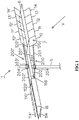
- FIG 4 schematically shows an aerofoil vane incorporating two lids according to the invention.
- the vane 6 has an aerofoil shape as known from WO2014/006075 .
- the lids 10 and 10' are hinged at the front (downstream tip) of the body of the vane.
- the lids are shown in a configuration wherein they are hinged away from the body of the vane, thus forming a receptacle 7 in its open configuration.
- FIG 5 shows a configuration of multiple separate lids that form one vane.
- the lids 10 to 12 and 10' to 12' are arranged in the same way as indicated in figure 1 . They are configured in two rows of consecutive lids, one at the top of the vane 6, the other at the bottom.
- Each lid is provided with one profile 500 (501, 502, 500', 501', 502') which corresponds in shape to the profile of figures 2 and 3 , having a tri-angular shaped cross-section.
- Example 1 provides data regarding energy conversion using models of a wind turbine according to the invention.
- three different models of a turbine are used.
- Each model comprises a support and connected thereto a vane having an aerofoil body with a length of 920 cm.
- To the body a row of 5 separate contiguous upper lids, and 5 separate contiguous lower lids are connected, the lid having lengths of about 20 cm.
- This configuration corresponds to the configuration of a vane as shown in figure 4 .
- the first model (Model “0") has no profiles protruding from the inner surfaces of the ten hinged lids.
- the second model (model “1") has six profiles, evenly distributed over the inner surfaces of the lids (three at the upper row and three at corresponding positions at the lower row).
- the profiles are triangular in cross-section, are non-diverging (they have an even cross section throughout their entire length) and have an even height of about 3 cm.
- the profiles extend from the upstream end of the lids to the downstream end adjacent the site where the lids hinge with respect to the body, and run exactly in a direction perpendicular to the longitudinal direction of the vane.
- the third model (model "2”) has ten profiles of the same configuration as the ones of model "1” and are also evenly distributed over the inner surfaces of the 10 lids (each lid having one profile).
- the model is statically positioned and wind at various speeds of 3, 4, 5, 6 and 7 m/s is blown against the vane with the lid in open position.
- the torque that the vane provides (in Nm) is measured at the support.
- the torque is average for the 5 different wind speeds. This number corresponds to the energy conversion capacity of the vane in when applied in an actual turbine.
- This average torque is measured for each model with the vane being positioned at different angles with respect to the wind.
- An angle of 0° means that the vane is exactly parallel to the wind
- an angle of 90° means that the vane is perpendicular to the direction of the wind).
Landscapes
- Engineering & Computer Science (AREA)
- Life Sciences & Earth Sciences (AREA)
- Sustainable Development (AREA)
- Sustainable Energy (AREA)
- Chemical & Material Sciences (AREA)
- Combustion & Propulsion (AREA)
- Mechanical Engineering (AREA)
- General Engineering & Computer Science (AREA)
- Physics & Mathematics (AREA)
- Fluid Mechanics (AREA)
- Wind Motors (AREA)
Claims (13)
- Windturbine zum Umwandeln von Wind in mechanische Energie, umfassend eine Stütze (5) und eine Schaufel (6, 16), die drehend mit der Stütze verbunden ist, wobei die Schaufel einen länglichen Körper und eine Windaufnahme (7) umfasst, die im Wesentlichen als eine Klappe (10-14) ausgebildet ist, die in Bezug auf den länglichen Körper derart geklappt werden kann, dass die Aufnahme eine offene Konfiguration, in der die Klappe von dem länglichen Körper weg geklappt ist, und eine geschlossene Konfiguration einnehmen kann, in der die Klappe zu dem Körper hin geklappt ist, wobei die Klappe eine Außenfläche aufweist, bei der es sich um die Fläche handelt, die von dem Wind abgewandt ist, wenn die Aufnahme die offene Konfiguration einnimmt, und eine entgegengesetzte Innenfläche, wobei die Innenfläche der Klappe mit einem oder mehreren Profilen (500, 501) versehen ist, die von der Innenfläche vorstehen und sich in einer zu der Längsrichtung der Schaufel rechtwinkeligen Richtung erstrecken, dadurch gekennzeichnet, dass das eine oder die mehreren Profile zu der Stelle hin auseinander laufen, an der die Klappe an dem Körper angelenkt ist.
- Windturbine nach Anspruch 1, dadurch gekennzeichnet, dass das eine oder die mehreren Profile kegelförmig sind und zu der Stelle hin auseinander laufen, an der die Klappe an dem Körper angelenkt ist.
- Windturbine nach einem der vorhergehenden Ansprüche, dadurch gekennzeichnet, dass das eine oder die mehreren Profile in Bezug auf die Innenfläche der Klappe eine Maximalhöhe aufweisen, die gleich mindestens 10 % der Länge der Klappe in der Längsrichtung der Schaufel ist.
- Windturbine nach einem der vorhergehenden Ansprüche, dadurch gekennzeichnet, dass das eine oder die mehreren Profile in Bezug auf die Innenfläche der Klappe eine Maximalhöhe aufweisen, die gleich mindestens 1 % der Länge der Klappe in der Längsrichtung der Schaufel ist.
- Windturbine nach einem der vorhergehenden Ansprüche, dadurch gekennzeichnet, dass die Schaufel ein tragflächenförmiger Körper ist, wobei die Klappe an einer zu einem stromabwärtigen Ende des Körpers benachbarten Position an dem Körper angelenkt ist.
- Windturbine nach einem der vorhergehenden Ansprüche, dadurch gekennzeichnet, dass die Schaufel mehrere Aufnahmen umfasst.
- Windturbine nach einem der vorhergehenden Ansprüche, dadurch gekennzeichnet, dass die Schaufel eine erste Aufnahme an einer Oberseite der Schaufel und eine zweite Aufnahme an einer Unterseite der Schaufel umfasst.
- Windturbine nach einem der vorhergehenden Ansprüche, dadurch gekennzeichnet, dass die Schaufel mehrere getrennte Aufnahmen umfasst, die entlang der Länge der Schaufel positioniert sind.
- Windturbine nach Anspruch 8, dadurch gekennzeichnet, dass jeder der mehreren getrennten Aufnahmen ein oder mehrere Profile nach Anspruch 1 umfasst.
- Windturbine nach einem der vorhergehenden Ansprüche, dadurch gekennzeichnet, dass die Turbine mit einem Mittel versehen ist, das dafür betriebsfähig ist, die Aufnahme zum Einnehmen der geschlossenen Konfiguration zu zwingen, wenn sich die Schaufel gegen die Richtung des Winds bewegt.
- Windturbine nach einem der vorhergehenden Ansprüche, dadurch gekennzeichnet, dass die Turbine mit einem Mittel versehen ist, das dafür betriebsfähig ist, die Aufnahme zum Einnehmen der geschlossenen Konfiguration zu zwingen, wenn sich die Schaufel in der Richtung des Winds bewegt.
- Verwendung einer Windturbine nach einem der vorhergehenden Ansprüche zum Umwandeln von Wind in Arbeit.
- Schaufel (6, 16), umfassend einen länglichen Körper und eine Windaufnahme, wobei die Schaufel im Wesentlichen als eine Klappe (10, 14) ausgebildet ist, die in Bezug auf den länglichen Körper derart geklappt werden kann, dass die Aufnahme (7) eine offene Konfiguration, in der die Klappe von dem länglichen Körper weg geklappt ist, und eine geschlossene Konfiguration einnehmen kann, in der die Klappe zu dem Körper hin geklappt ist, wobei die Klappe eine Außenfläche aufweist, bei der es sich um die Fläche handelt, die von dem Wind abgewandt ist, wenn die Aufnahme die offene Konfiguration einnimmt, und eine entgegengesetzte Innenfläche, wobei die Innenfläche der Klappe mit einem oder mehreren Profilen (500, 501) versehen ist, die von der Innenfläche vorstehen und sich in einer zu der Längsrichtung der Schaufel rechtwinkeligen Richtung erstrecken, dadurch gekennzeichnet, dass das eine oder die mehreren Profile zu der Stelle hin auseinander laufen, an der die Klappe an dem Körper angelenkt ist.
Applications Claiming Priority (2)
| Application Number | Priority Date | Filing Date | Title |
|---|---|---|---|
| EP16153987.9A EP3203063A1 (de) | 2016-02-03 | 2016-02-03 | Windturbine, deren verwendung und schaufel zur verwendung in der turbine |
| PCT/EP2017/052219 WO2017134145A1 (en) | 2016-02-03 | 2017-02-02 | Wind turbine, its use and a vane for use in the turbine |
Publications (2)
| Publication Number | Publication Date |
|---|---|
| EP3411593A1 EP3411593A1 (de) | 2018-12-12 |
| EP3411593B1 true EP3411593B1 (de) | 2019-10-02 |
Family
ID=55299348
Family Applications (2)
| Application Number | Title | Priority Date | Filing Date |
|---|---|---|---|
| EP16153987.9A Withdrawn EP3203063A1 (de) | 2016-02-03 | 2016-02-03 | Windturbine, deren verwendung und schaufel zur verwendung in der turbine |
| EP17705039.0A Active EP3411593B1 (de) | 2016-02-03 | 2017-02-02 | Windturbine, deren verwendung und schaufel zur verwendung in der turbine |
Family Applications Before (1)
| Application Number | Title | Priority Date | Filing Date |
|---|---|---|---|
| EP16153987.9A Withdrawn EP3203063A1 (de) | 2016-02-03 | 2016-02-03 | Windturbine, deren verwendung und schaufel zur verwendung in der turbine |
Country Status (8)
| Country | Link |
|---|---|
| US (1) | US10359024B2 (de) |
| EP (2) | EP3203063A1 (de) |
| JP (1) | JP2019508618A (de) |
| KR (1) | KR20180108611A (de) |
| CN (1) | CN108603489B (de) |
| BR (1) | BR112018014492A2 (de) |
| ES (1) | ES2763400T3 (de) |
| WO (1) | WO2017134145A1 (de) |
Families Citing this family (4)
| Publication number | Priority date | Publication date | Assignee | Title |
|---|---|---|---|---|
| RU2015133209A (ru) | 2013-01-08 | 2017-02-15 | Кэпниа, Инк. | Выбор дыхательного цикла для анализа |
| RU2016111654A (ru) | 2013-08-30 | 2017-10-05 | Кэпниа, Инк. | Система измерения углекислого газа у новорожденных |
| US20190040867A1 (en) * | 2017-08-02 | 2019-02-07 | Poolstar Canada Limited | Hydraulic rotary drive |
| JP7045102B1 (ja) | 2020-10-28 | 2022-03-31 | 正樹 長谷川 | 風力原動機 |
Family Cites Families (21)
| Publication number | Priority date | Publication date | Assignee | Title |
|---|---|---|---|---|
| CN2258234Y (zh) * | 1994-08-09 | 1997-07-23 | 严锡春 | 一种风能动力机 |
| US5570997A (en) | 1995-07-17 | 1996-11-05 | Pratt; Charles W. | Horizontal windmill with folding blades |
| DE29608787U1 (de) * | 1996-05-15 | 1996-08-08 | Freimund, Wolfgang, 22179 Hamburg | Windkraftanlage |
| DE19802899A1 (de) | 1998-01-27 | 1999-08-05 | Helmut Kaeferstein | Windkraftrotor zur Strömungsnutzung |
| US6682302B2 (en) * | 2001-03-20 | 2004-01-27 | James D. Noble | Turbine apparatus and method |
| JP2007270746A (ja) * | 2006-03-31 | 2007-10-18 | Univ Nihon | 可変翼を有する垂直軸形風水車 |
| DK3617496T3 (da) * | 2006-04-02 | 2024-12-02 | Wobben Properties Gmbh | Vindmølle med tynd vinge |
| US20080019832A1 (en) * | 2006-07-10 | 2008-01-24 | Thomas Anderson | Turbine/rotorcraft/oar blade |
| US8164210B2 (en) | 2007-03-07 | 2012-04-24 | Boone Daniel N | Vertical axis wind turbine with angled braces |
| CN101182830A (zh) * | 2007-12-18 | 2008-05-21 | 王掊陌 | 迎风启闭式帆叶风轮 |
| WO2009153772A1 (en) * | 2008-06-20 | 2009-12-23 | Nathan Kirpitznikoff | Wind turbine |
| US8282350B2 (en) * | 2009-07-29 | 2012-10-09 | The Corrado Family Limited Partnership, L.L.C. | Method and apparatus for capturing wind to produce electrical power |
| US20120267895A1 (en) * | 2009-09-08 | 2012-10-25 | Atlantis Resources Corporation Pte Limited | Power generator |
| CN101737252A (zh) | 2009-12-09 | 2010-06-16 | 哈尔滨工业大学 | 一种用于垂直轴风力机的辅助启动装置 |
| CN201771673U (zh) * | 2009-12-30 | 2011-03-23 | 力仓风力设备(上海)有限公司 | 风电叶片表面之涡流发生器 |
| US8702393B2 (en) * | 2010-08-21 | 2014-04-22 | Jasim Saleh Al-Azzawi | Blinking sail windmill with safety control |
| IT1402145B1 (it) | 2010-09-29 | 2013-08-28 | Univ Palermo | Turbina eolica a pale oscillanti ad elevato rendimento |
| JP5567547B2 (ja) * | 2011-12-27 | 2014-08-06 | 修 小林 | 動力発生装置及びこれを用いた垂直軸発電装置 |
| GB2498594A (en) * | 2012-01-23 | 2013-07-24 | Arthur William George Hetherington | Vertical axis wind turbine with hinged vanes |
| BR112014031624B1 (pt) * | 2012-07-06 | 2022-03-29 | Wilhelmus Helena Hendrikus Joosten | Turbina eólica para a conversão de vento em energia mecânica e uso de uma turbina eólica |
| US20150010407A1 (en) * | 2013-07-08 | 2015-01-08 | Alonso O. Zamora Rodriguez | Reduced noise vortex generator for wind turbine blade |
-
2016
- 2016-02-03 EP EP16153987.9A patent/EP3203063A1/de not_active Withdrawn
-
2017
- 2017-02-02 CN CN201780009679.2A patent/CN108603489B/zh active Active
- 2017-02-02 ES ES17705039T patent/ES2763400T3/es active Active
- 2017-02-02 JP JP2018540375A patent/JP2019508618A/ja active Pending
- 2017-02-02 WO PCT/EP2017/052219 patent/WO2017134145A1/en not_active Ceased
- 2017-02-02 US US16/070,452 patent/US10359024B2/en active Active
- 2017-02-02 BR BR112018014492-4A patent/BR112018014492A2/pt not_active Application Discontinuation
- 2017-02-02 EP EP17705039.0A patent/EP3411593B1/de active Active
- 2017-02-02 KR KR1020187021367A patent/KR20180108611A/ko not_active Ceased
Non-Patent Citations (1)
| Title |
|---|
| None * |
Also Published As
| Publication number | Publication date |
|---|---|
| US10359024B2 (en) | 2019-07-23 |
| CN108603489B (zh) | 2020-06-02 |
| KR20180108611A (ko) | 2018-10-04 |
| EP3203063A1 (de) | 2017-08-09 |
| EP3411593A1 (de) | 2018-12-12 |
| ES2763400T3 (es) | 2020-05-28 |
| US20190024632A1 (en) | 2019-01-24 |
| CN108603489A (zh) | 2018-09-28 |
| BR112018014492A2 (pt) | 2018-12-11 |
| JP2019508618A (ja) | 2019-03-28 |
| WO2017134145A1 (en) | 2017-08-10 |
Similar Documents
| Publication | Publication Date | Title |
|---|---|---|
| US10145358B2 (en) | Wind turbine, its use and a vane for use in the turbine | |
| US10260479B2 (en) | Vortex propeller | |
| US4504192A (en) | Jet spoiler arrangement for wind turbine | |
| US5577882A (en) | Unidirectional reaction turbine operable under reversible fluid flow | |
| US10359024B2 (en) | Wind turbine, its use and a vane for use in the turbine | |
| EP3207244B1 (de) | Turbine mit strömungsumlenker und strömungsumlenker für turbinen | |
| CA2608284A1 (en) | Helical wind turbine | |
| JP2002503309A (ja) | 水力発電所の水車タービン | |
| KR101817229B1 (ko) | 다중 풍력발전장치 | |
| CN102369351A (zh) | 水轮 | |
| KR101455900B1 (ko) | 날개 각도 가변 구조를 가진 수직축 풍력 발전기 | |
| EP2541048A2 (de) | Tragfläche, Windrotor und Windrotoranordnung | |
| KR20130024612A (ko) | 풍력 발전기용 가변형 블레이드 | |
| KR101851102B1 (ko) | 전기 자동차에 장착되는 양력을 이용한 풍력 발전 장치 | |
| JP3135220U (ja) | 風力発電機 | |
| KR101409717B1 (ko) | 임펠러 좌우 변위형 풍력발전시스템 | |
| EP2514963A1 (de) | Windturbine, deren Verwendung und Schaufel zur Verwendung in der Turbine | |
| NL1035478C2 (nl) | Waterrad met zelfstellende diagonale schoepen. | |
| JP2018178984A (ja) | 抗力型開閉式発電機 | |
| WO2017096460A1 (en) | Wind turbine with hinged blades | |
| KR20110094822A (ko) | 풍력 발전기의 최대출력을 위한 육각 기둥 형태의 수직축 집 풍 장치 | |
| UA28687U (en) | Wind-driven power plant |
Legal Events
| Date | Code | Title | Description |
|---|---|---|---|
| STAA | Information on the status of an ep patent application or granted ep patent |
Free format text: STATUS: UNKNOWN |
|
| STAA | Information on the status of an ep patent application or granted ep patent |
Free format text: STATUS: THE INTERNATIONAL PUBLICATION HAS BEEN MADE |
|
| PUAI | Public reference made under article 153(3) epc to a published international application that has entered the european phase |
Free format text: ORIGINAL CODE: 0009012 |
|
| STAA | Information on the status of an ep patent application or granted ep patent |
Free format text: STATUS: REQUEST FOR EXAMINATION WAS MADE |
|
| 17P | Request for examination filed |
Effective date: 20180815 |
|
| AK | Designated contracting states |
Kind code of ref document: A1 Designated state(s): AL AT BE BG CH CY CZ DE DK EE ES FI FR GB GR HR HU IE IS IT LI LT LU LV MC MK MT NL NO PL PT RO RS SE SI SK SM TR |
|
| AX | Request for extension of the european patent |
Extension state: BA ME |
|
| DAV | Request for validation of the european patent (deleted) | ||
| DAX | Request for extension of the european patent (deleted) | ||
| GRAP | Despatch of communication of intention to grant a patent |
Free format text: ORIGINAL CODE: EPIDOSNIGR1 |
|
| STAA | Information on the status of an ep patent application or granted ep patent |
Free format text: STATUS: GRANT OF PATENT IS INTENDED |
|
| INTG | Intention to grant announced |
Effective date: 20190528 |
|
| GRAS | Grant fee paid |
Free format text: ORIGINAL CODE: EPIDOSNIGR3 |
|
| GRAA | (expected) grant |
Free format text: ORIGINAL CODE: 0009210 |
|
| STAA | Information on the status of an ep patent application or granted ep patent |
Free format text: STATUS: THE PATENT HAS BEEN GRANTED |
|
| AK | Designated contracting states |
Kind code of ref document: B1 Designated state(s): AL AT BE BG CH CY CZ DE DK EE ES FI FR GB GR HR HU IE IS IT LI LT LU LV MC MK MT NL NO PL PT RO RS SE SI SK SM TR |
|
| REG | Reference to a national code |
Ref country code: GB Ref legal event code: FG4D |
|
| REG | Reference to a national code |
Ref country code: CH Ref legal event code: EP Ref country code: AT Ref legal event code: REF Ref document number: 1186449 Country of ref document: AT Kind code of ref document: T Effective date: 20191015 |
|
| REG | Reference to a national code |
Ref country code: DE Ref legal event code: R096 Ref document number: 602017007483 Country of ref document: DE |
|
| REG | Reference to a national code |
Ref country code: IE Ref legal event code: FG4D |
|
| REG | Reference to a national code |
Ref country code: NL Ref legal event code: FP |
|
| REG | Reference to a national code |
Ref country code: LT Ref legal event code: MG4D |
|
| REG | Reference to a national code |
Ref country code: AT Ref legal event code: MK05 Ref document number: 1186449 Country of ref document: AT Kind code of ref document: T Effective date: 20191002 |
|
| PG25 | Lapsed in a contracting state [announced via postgrant information from national office to epo] |
Ref country code: LV Free format text: LAPSE BECAUSE OF FAILURE TO SUBMIT A TRANSLATION OF THE DESCRIPTION OR TO PAY THE FEE WITHIN THE PRESCRIBED TIME-LIMIT Effective date: 20191002 Ref country code: SE Free format text: LAPSE BECAUSE OF FAILURE TO SUBMIT A TRANSLATION OF THE DESCRIPTION OR TO PAY THE FEE WITHIN THE PRESCRIBED TIME-LIMIT Effective date: 20191002 Ref country code: AT Free format text: LAPSE BECAUSE OF FAILURE TO SUBMIT A TRANSLATION OF THE DESCRIPTION OR TO PAY THE FEE WITHIN THE PRESCRIBED TIME-LIMIT Effective date: 20191002 Ref country code: PT Free format text: LAPSE BECAUSE OF FAILURE TO SUBMIT A TRANSLATION OF THE DESCRIPTION OR TO PAY THE FEE WITHIN THE PRESCRIBED TIME-LIMIT Effective date: 20200203 Ref country code: BG Free format text: LAPSE BECAUSE OF FAILURE TO SUBMIT A TRANSLATION OF THE DESCRIPTION OR TO PAY THE FEE WITHIN THE PRESCRIBED TIME-LIMIT Effective date: 20200102 Ref country code: FI Free format text: LAPSE BECAUSE OF FAILURE TO SUBMIT A TRANSLATION OF THE DESCRIPTION OR TO PAY THE FEE WITHIN THE PRESCRIBED TIME-LIMIT Effective date: 20191002 Ref country code: LT Free format text: LAPSE BECAUSE OF FAILURE TO SUBMIT A TRANSLATION OF THE DESCRIPTION OR TO PAY THE FEE WITHIN THE PRESCRIBED TIME-LIMIT Effective date: 20191002 Ref country code: GR Free format text: LAPSE BECAUSE OF FAILURE TO SUBMIT A TRANSLATION OF THE DESCRIPTION OR TO PAY THE FEE WITHIN THE PRESCRIBED TIME-LIMIT Effective date: 20200103 Ref country code: NO Free format text: LAPSE BECAUSE OF FAILURE TO SUBMIT A TRANSLATION OF THE DESCRIPTION OR TO PAY THE FEE WITHIN THE PRESCRIBED TIME-LIMIT Effective date: 20200102 Ref country code: PL Free format text: LAPSE BECAUSE OF FAILURE TO SUBMIT A TRANSLATION OF THE DESCRIPTION OR TO PAY THE FEE WITHIN THE PRESCRIBED TIME-LIMIT Effective date: 20191002 |
|
| REG | Reference to a national code |
Ref country code: ES Ref legal event code: FG2A Ref document number: 2763400 Country of ref document: ES Kind code of ref document: T3 Effective date: 20200528 |
|
| PG25 | Lapsed in a contracting state [announced via postgrant information from national office to epo] |
Ref country code: HR Free format text: LAPSE BECAUSE OF FAILURE TO SUBMIT A TRANSLATION OF THE DESCRIPTION OR TO PAY THE FEE WITHIN THE PRESCRIBED TIME-LIMIT Effective date: 20191002 Ref country code: RS Free format text: LAPSE BECAUSE OF FAILURE TO SUBMIT A TRANSLATION OF THE DESCRIPTION OR TO PAY THE FEE WITHIN THE PRESCRIBED TIME-LIMIT Effective date: 20191002 Ref country code: CZ Free format text: LAPSE BECAUSE OF FAILURE TO SUBMIT A TRANSLATION OF THE DESCRIPTION OR TO PAY THE FEE WITHIN THE PRESCRIBED TIME-LIMIT Effective date: 20191002 Ref country code: IS Free format text: LAPSE BECAUSE OF FAILURE TO SUBMIT A TRANSLATION OF THE DESCRIPTION OR TO PAY THE FEE WITHIN THE PRESCRIBED TIME-LIMIT Effective date: 20200224 |
|
| PG25 | Lapsed in a contracting state [announced via postgrant information from national office to epo] |
Ref country code: AL Free format text: LAPSE BECAUSE OF FAILURE TO SUBMIT A TRANSLATION OF THE DESCRIPTION OR TO PAY THE FEE WITHIN THE PRESCRIBED TIME-LIMIT Effective date: 20191002 |
|
| REG | Reference to a national code |
Ref country code: DE Ref legal event code: R097 Ref document number: 602017007483 Country of ref document: DE |
|
| PG2D | Information on lapse in contracting state deleted |
Ref country code: IS |
|
| PG25 | Lapsed in a contracting state [announced via postgrant information from national office to epo] |
Ref country code: RO Free format text: LAPSE BECAUSE OF FAILURE TO SUBMIT A TRANSLATION OF THE DESCRIPTION OR TO PAY THE FEE WITHIN THE PRESCRIBED TIME-LIMIT Effective date: 20191002 Ref country code: EE Free format text: LAPSE BECAUSE OF FAILURE TO SUBMIT A TRANSLATION OF THE DESCRIPTION OR TO PAY THE FEE WITHIN THE PRESCRIBED TIME-LIMIT Effective date: 20191002 Ref country code: DK Free format text: LAPSE BECAUSE OF FAILURE TO SUBMIT A TRANSLATION OF THE DESCRIPTION OR TO PAY THE FEE WITHIN THE PRESCRIBED TIME-LIMIT Effective date: 20191002 Ref country code: IS Free format text: LAPSE BECAUSE OF FAILURE TO SUBMIT A TRANSLATION OF THE DESCRIPTION OR TO PAY THE FEE WITHIN THE PRESCRIBED TIME-LIMIT Effective date: 20200202 |
|
| PLBE | No opposition filed within time limit |
Free format text: ORIGINAL CODE: 0009261 |
|
| STAA | Information on the status of an ep patent application or granted ep patent |
Free format text: STATUS: NO OPPOSITION FILED WITHIN TIME LIMIT |
|
| PG25 | Lapsed in a contracting state [announced via postgrant information from national office to epo] |
Ref country code: SK Free format text: LAPSE BECAUSE OF FAILURE TO SUBMIT A TRANSLATION OF THE DESCRIPTION OR TO PAY THE FEE WITHIN THE PRESCRIBED TIME-LIMIT Effective date: 20191002 Ref country code: SM Free format text: LAPSE BECAUSE OF FAILURE TO SUBMIT A TRANSLATION OF THE DESCRIPTION OR TO PAY THE FEE WITHIN THE PRESCRIBED TIME-LIMIT Effective date: 20191002 |
|
| 26N | No opposition filed |
Effective date: 20200703 |
|
| REG | Reference to a national code |
Ref country code: CH Ref legal event code: PL |
|
| REG | Reference to a national code |
Ref country code: BE Ref legal event code: MM Effective date: 20200229 |
|
| PG25 | Lapsed in a contracting state [announced via postgrant information from national office to epo] |
Ref country code: MC Free format text: LAPSE BECAUSE OF FAILURE TO SUBMIT A TRANSLATION OF THE DESCRIPTION OR TO PAY THE FEE WITHIN THE PRESCRIBED TIME-LIMIT Effective date: 20191002 Ref country code: LU Free format text: LAPSE BECAUSE OF NON-PAYMENT OF DUE FEES Effective date: 20200202 |
|
| PG25 | Lapsed in a contracting state [announced via postgrant information from national office to epo] |
Ref country code: SI Free format text: LAPSE BECAUSE OF FAILURE TO SUBMIT A TRANSLATION OF THE DESCRIPTION OR TO PAY THE FEE WITHIN THE PRESCRIBED TIME-LIMIT Effective date: 20191002 Ref country code: CH Free format text: LAPSE BECAUSE OF NON-PAYMENT OF DUE FEES Effective date: 20200229 Ref country code: LI Free format text: LAPSE BECAUSE OF NON-PAYMENT OF DUE FEES Effective date: 20200229 |
|
| PG25 | Lapsed in a contracting state [announced via postgrant information from national office to epo] |
Ref country code: IE Free format text: LAPSE BECAUSE OF NON-PAYMENT OF DUE FEES Effective date: 20200202 |
|
| PG25 | Lapsed in a contracting state [announced via postgrant information from national office to epo] |
Ref country code: BE Free format text: LAPSE BECAUSE OF NON-PAYMENT OF DUE FEES Effective date: 20200229 |
|
| PG25 | Lapsed in a contracting state [announced via postgrant information from national office to epo] |
Ref country code: TR Free format text: LAPSE BECAUSE OF FAILURE TO SUBMIT A TRANSLATION OF THE DESCRIPTION OR TO PAY THE FEE WITHIN THE PRESCRIBED TIME-LIMIT Effective date: 20191002 Ref country code: MT Free format text: LAPSE BECAUSE OF FAILURE TO SUBMIT A TRANSLATION OF THE DESCRIPTION OR TO PAY THE FEE WITHIN THE PRESCRIBED TIME-LIMIT Effective date: 20191002 Ref country code: CY Free format text: LAPSE BECAUSE OF FAILURE TO SUBMIT A TRANSLATION OF THE DESCRIPTION OR TO PAY THE FEE WITHIN THE PRESCRIBED TIME-LIMIT Effective date: 20191002 |
|
| PG25 | Lapsed in a contracting state [announced via postgrant information from national office to epo] |
Ref country code: MK Free format text: LAPSE BECAUSE OF FAILURE TO SUBMIT A TRANSLATION OF THE DESCRIPTION OR TO PAY THE FEE WITHIN THE PRESCRIBED TIME-LIMIT Effective date: 20191002 |
|
| PGFP | Annual fee paid to national office [announced via postgrant information from national office to epo] |
Ref country code: NL Payment date: 20250227 Year of fee payment: 9 |
|
| PGFP | Annual fee paid to national office [announced via postgrant information from national office to epo] |
Ref country code: DE Payment date: 20250227 Year of fee payment: 9 |
|
| PGFP | Annual fee paid to national office [announced via postgrant information from national office to epo] |
Ref country code: ES Payment date: 20250303 Year of fee payment: 9 |
|
| PGFP | Annual fee paid to national office [announced via postgrant information from national office to epo] |
Ref country code: FR Payment date: 20250225 Year of fee payment: 9 |
|
| PGFP | Annual fee paid to national office [announced via postgrant information from national office to epo] |
Ref country code: IT Payment date: 20250220 Year of fee payment: 9 Ref country code: GB Payment date: 20250227 Year of fee payment: 9 |