EP3411632B1 - Wandbauteil für eine wandheizung und wandheizung - Google Patents
Wandbauteil für eine wandheizung und wandheizung Download PDFInfo
- Publication number
- EP3411632B1 EP3411632B1 EP17706684.2A EP17706684A EP3411632B1 EP 3411632 B1 EP3411632 B1 EP 3411632B1 EP 17706684 A EP17706684 A EP 17706684A EP 3411632 B1 EP3411632 B1 EP 3411632B1
- Authority
- EP
- European Patent Office
- Prior art keywords
- base plate
- cover
- wall
- heater according
- wall heater
- Prior art date
- Legal status (The legal status is an assumption and is not a legal conclusion. Google has not performed a legal analysis and makes no representation as to the accuracy of the status listed.)
- Active
Links
Images




Classifications
-
- F—MECHANICAL ENGINEERING; LIGHTING; HEATING; WEAPONS; BLASTING
- F28—HEAT EXCHANGE IN GENERAL
- F28D—HEAT-EXCHANGE APPARATUS, NOT PROVIDED FOR IN ANOTHER SUBCLASS, IN WHICH THE HEAT-EXCHANGE MEDIA DO NOT COME INTO DIRECT CONTACT
- F28D1/00—Heat-exchange apparatus having stationary conduit assemblies for one heat-exchange medium only, the media being in contact with different sides of the conduit wall, in which the other heat-exchange medium is a large body of fluid, e.g. domestic or motor car radiators
- F28D1/02—Heat-exchange apparatus having stationary conduit assemblies for one heat-exchange medium only, the media being in contact with different sides of the conduit wall, in which the other heat-exchange medium is a large body of fluid, e.g. domestic or motor car radiators with heat-exchange conduits immersed in the body of fluid
- F28D1/03—Heat-exchange apparatus having stationary conduit assemblies for one heat-exchange medium only, the media being in contact with different sides of the conduit wall, in which the other heat-exchange medium is a large body of fluid, e.g. domestic or motor car radiators with heat-exchange conduits immersed in the body of fluid with plate-like or laminated conduits
- F28D1/0366—Heat-exchange apparatus having stationary conduit assemblies for one heat-exchange medium only, the media being in contact with different sides of the conduit wall, in which the other heat-exchange medium is a large body of fluid, e.g. domestic or motor car radiators with heat-exchange conduits immersed in the body of fluid with plate-like or laminated conduits the conduits being formed by spaced plates with inserted elements
-
- E—FIXED CONSTRUCTIONS
- E04—BUILDING
- E04C—STRUCTURAL ELEMENTS; BUILDING MATERIALS
- E04C2/00—Building elements of relatively thin form for the construction of parts of buildings, e.g. sheet materials, slabs, or panels
- E04C2/30—Building elements of relatively thin form for the construction of parts of buildings, e.g. sheet materials, slabs, or panels characterised by the shape or structure
- E04C2/32—Building elements of relatively thin form for the construction of parts of buildings, e.g. sheet materials, slabs, or panels characterised by the shape or structure formed of corrugated or otherwise indented sheet-like material; composed of such layers with or without layers of flat sheet-like material
- E04C2/322—Building elements of relatively thin form for the construction of parts of buildings, e.g. sheet materials, slabs, or panels characterised by the shape or structure formed of corrugated or otherwise indented sheet-like material; composed of such layers with or without layers of flat sheet-like material with parallel corrugations
-
- E—FIXED CONSTRUCTIONS
- E04—BUILDING
- E04C—STRUCTURAL ELEMENTS; BUILDING MATERIALS
- E04C2/00—Building elements of relatively thin form for the construction of parts of buildings, e.g. sheet materials, slabs, or panels
- E04C2/30—Building elements of relatively thin form for the construction of parts of buildings, e.g. sheet materials, slabs, or panels characterised by the shape or structure
- E04C2/38—Building elements of relatively thin form for the construction of parts of buildings, e.g. sheet materials, slabs, or panels characterised by the shape or structure with attached ribs, flanges, or the like, e.g. framed panels
-
- E—FIXED CONSTRUCTIONS
- E04—BUILDING
- E04C—STRUCTURAL ELEMENTS; BUILDING MATERIALS
- E04C2/00—Building elements of relatively thin form for the construction of parts of buildings, e.g. sheet materials, slabs, or panels
- E04C2/30—Building elements of relatively thin form for the construction of parts of buildings, e.g. sheet materials, slabs, or panels characterised by the shape or structure
- E04C2/40—Building elements of relatively thin form for the construction of parts of buildings, e.g. sheet materials, slabs, or panels characterised by the shape or structure composed of a number of smaller components rigidly or movably connected together, e.g. interlocking, hingedly connected of particular shape, e.g. not rectangular of variable shape or size, e.g. flexible or telescopic panels
- E04C2/405—Building elements of relatively thin form for the construction of parts of buildings, e.g. sheet materials, slabs, or panels characterised by the shape or structure composed of a number of smaller components rigidly or movably connected together, e.g. interlocking, hingedly connected of particular shape, e.g. not rectangular of variable shape or size, e.g. flexible or telescopic panels composed of two or more hingedly connected parts
-
- E—FIXED CONSTRUCTIONS
- E04—BUILDING
- E04C—STRUCTURAL ELEMENTS; BUILDING MATERIALS
- E04C2/00—Building elements of relatively thin form for the construction of parts of buildings, e.g. sheet materials, slabs, or panels
- E04C2/44—Building elements of relatively thin form for the construction of parts of buildings, e.g. sheet materials, slabs, or panels characterised by the purpose
- E04C2/52—Building elements of relatively thin form for the construction of parts of buildings, e.g. sheet materials, slabs, or panels characterised by the purpose with special adaptations for auxiliary purposes, e.g. serving for locating conduits
- E04C2/521—Building elements of relatively thin form for the construction of parts of buildings, e.g. sheet materials, slabs, or panels characterised by the purpose with special adaptations for auxiliary purposes, e.g. serving for locating conduits serving for locating conduits; for ventilating, heating or cooling
- E04C2/525—Building elements of relatively thin form for the construction of parts of buildings, e.g. sheet materials, slabs, or panels characterised by the purpose with special adaptations for auxiliary purposes, e.g. serving for locating conduits serving for locating conduits; for ventilating, heating or cooling for heating or cooling
-
- F—MECHANICAL ENGINEERING; LIGHTING; HEATING; WEAPONS; BLASTING
- F24—HEATING; RANGES; VENTILATING
- F24D—DOMESTIC- OR SPACE-HEATING SYSTEMS, e.g. CENTRAL HEATING SYSTEMS; DOMESTIC HOT-WATER SUPPLY SYSTEMS; ELEMENTS OR COMPONENTS THEREFOR
- F24D3/00—Hot-water central heating systems
- F24D3/12—Tube and panel arrangements for ceiling, wall, or underfloor heating
- F24D3/14—Tube and panel arrangements for ceiling, wall, or underfloor heating incorporated in a ceiling, wall or floor
-
- F—MECHANICAL ENGINEERING; LIGHTING; HEATING; WEAPONS; BLASTING
- F24—HEATING; RANGES; VENTILATING
- F24F—AIR-CONDITIONING; AIR-HUMIDIFICATION; VENTILATION; USE OF AIR CURRENTS FOR SCREENING
- F24F5/00—Air-conditioning systems or apparatus not covered by F24F1/00 or F24F3/00, e.g. using solar heat or combined with household units such as an oven or water heater
- F24F5/0075—Systems using thermal walls, e.g. double window
-
- F—MECHANICAL ENGINEERING; LIGHTING; HEATING; WEAPONS; BLASTING
- F28—HEAT EXCHANGE IN GENERAL
- F28D—HEAT-EXCHANGE APPARATUS, NOT PROVIDED FOR IN ANOTHER SUBCLASS, IN WHICH THE HEAT-EXCHANGE MEDIA DO NOT COME INTO DIRECT CONTACT
- F28D1/00—Heat-exchange apparatus having stationary conduit assemblies for one heat-exchange medium only, the media being in contact with different sides of the conduit wall, in which the other heat-exchange medium is a large body of fluid, e.g. domestic or motor car radiators
- F28D1/02—Heat-exchange apparatus having stationary conduit assemblies for one heat-exchange medium only, the media being in contact with different sides of the conduit wall, in which the other heat-exchange medium is a large body of fluid, e.g. domestic or motor car radiators with heat-exchange conduits immersed in the body of fluid
- F28D1/03—Heat-exchange apparatus having stationary conduit assemblies for one heat-exchange medium only, the media being in contact with different sides of the conduit wall, in which the other heat-exchange medium is a large body of fluid, e.g. domestic or motor car radiators with heat-exchange conduits immersed in the body of fluid with plate-like or laminated conduits
- F28D1/0308—Heat-exchange apparatus having stationary conduit assemblies for one heat-exchange medium only, the media being in contact with different sides of the conduit wall, in which the other heat-exchange medium is a large body of fluid, e.g. domestic or motor car radiators with heat-exchange conduits immersed in the body of fluid with plate-like or laminated conduits the conduits being formed by paired plates touching each other
-
- F—MECHANICAL ENGINEERING; LIGHTING; HEATING; WEAPONS; BLASTING
- F28—HEAT EXCHANGE IN GENERAL
- F28F—DETAILS OF HEAT-EXCHANGE AND HEAT-TRANSFER APPARATUS, OF GENERAL APPLICATION
- F28F3/00—Plate-like or laminated elements; Assemblies of plate-like or laminated elements
- F28F3/12—Elements constructed in the shape of a hollow panel, e.g. with channels
-
- E—FIXED CONSTRUCTIONS
- E04—BUILDING
- E04F—FINISHING WORK ON BUILDINGS, e.g. STAIRS, FLOORS
- E04F13/00—Coverings or linings, e.g. for walls or ceilings
- E04F13/007—Outer coverings for walls with ventilating means
-
- F—MECHANICAL ENGINEERING; LIGHTING; HEATING; WEAPONS; BLASTING
- F28—HEAT EXCHANGE IN GENERAL
- F28D—HEAT-EXCHANGE APPARATUS, NOT PROVIDED FOR IN ANOTHER SUBCLASS, IN WHICH THE HEAT-EXCHANGE MEDIA DO NOT COME INTO DIRECT CONTACT
- F28D21/00—Heat-exchange apparatus not covered by any of the groups F28D1/00 - F28D20/00
- F28D2021/0019—Other heat exchangers for particular applications; Heat exchange systems not otherwise provided for
- F28D2021/0035—Other heat exchangers for particular applications; Heat exchange systems not otherwise provided for for domestic or space heating, e.g. heating radiators
-
- F—MECHANICAL ENGINEERING; LIGHTING; HEATING; WEAPONS; BLASTING
- F28—HEAT EXCHANGE IN GENERAL
- F28F—DETAILS OF HEAT-EXCHANGE AND HEAT-TRANSFER APPARATUS, OF GENERAL APPLICATION
- F28F2275/00—Fastening; Joining
- F28F2275/14—Fastening; Joining by using form fitting connection, e.g. with tongue and groove
-
- F—MECHANICAL ENGINEERING; LIGHTING; HEATING; WEAPONS; BLASTING
- F28—HEAT EXCHANGE IN GENERAL
- F28F—DETAILS OF HEAT-EXCHANGE AND HEAT-TRANSFER APPARATUS, OF GENERAL APPLICATION
- F28F2280/00—Mounting arrangements; Arrangements for facilitating assembling or disassembling of heat exchanger parts
- F28F2280/10—Movable elements, e.g. being pivotable
- F28F2280/105—Movable elements, e.g. being pivotable with hinged connections
-
- Y—GENERAL TAGGING OF NEW TECHNOLOGICAL DEVELOPMENTS; GENERAL TAGGING OF CROSS-SECTIONAL TECHNOLOGIES SPANNING OVER SEVERAL SECTIONS OF THE IPC; TECHNICAL SUBJECTS COVERED BY FORMER USPC CROSS-REFERENCE ART COLLECTIONS [XRACs] AND DIGESTS
- Y02—TECHNOLOGIES OR APPLICATIONS FOR MITIGATION OR ADAPTATION AGAINST CLIMATE CHANGE
- Y02A—TECHNOLOGIES FOR ADAPTATION TO CLIMATE CHANGE
- Y02A30/00—Adapting or protecting infrastructure or their operation
-
- Y—GENERAL TAGGING OF NEW TECHNOLOGICAL DEVELOPMENTS; GENERAL TAGGING OF CROSS-SECTIONAL TECHNOLOGIES SPANNING OVER SEVERAL SECTIONS OF THE IPC; TECHNICAL SUBJECTS COVERED BY FORMER USPC CROSS-REFERENCE ART COLLECTIONS [XRACs] AND DIGESTS
- Y02—TECHNOLOGIES OR APPLICATIONS FOR MITIGATION OR ADAPTATION AGAINST CLIMATE CHANGE
- Y02B—CLIMATE CHANGE MITIGATION TECHNOLOGIES RELATED TO BUILDINGS, e.g. HOUSING, HOUSE APPLIANCES OR RELATED END-USER APPLICATIONS
- Y02B30/00—Energy efficient heating, ventilation or air conditioning [HVAC]
-
- Y—GENERAL TAGGING OF NEW TECHNOLOGICAL DEVELOPMENTS; GENERAL TAGGING OF CROSS-SECTIONAL TECHNOLOGIES SPANNING OVER SEVERAL SECTIONS OF THE IPC; TECHNICAL SUBJECTS COVERED BY FORMER USPC CROSS-REFERENCE ART COLLECTIONS [XRACs] AND DIGESTS
- Y02—TECHNOLOGIES OR APPLICATIONS FOR MITIGATION OR ADAPTATION AGAINST CLIMATE CHANGE
- Y02B—CLIMATE CHANGE MITIGATION TECHNOLOGIES RELATED TO BUILDINGS, e.g. HOUSING, HOUSE APPLIANCES OR RELATED END-USER APPLICATIONS
- Y02B30/00—Energy efficient heating, ventilation or air conditioning [HVAC]
- Y02B30/90—Passive houses; Double facade technology
Definitions
- the invention relates to a wall heater according to the preamble of claim 1.
- Such a wall component is used to direct air from an air source within a building through its walls to building interiors.
- the groove of the profiling of a base plate forms a flow channel with the cover attached to the base plate.
- a wall heater with a wall component in which a radiator is integrated.
- the wall component has a base plate and a cover that can be placed on the base plate. In the lower area, several inflow openings are formed in the cover, through which the air to be heated can be fed from the interior of a building to the radiator arranged within the wall component.
- the air heated by the radiator rises within the wall component and exits through a number of outflow openings formed in the upper area of the cover. Since the radiator is firmly integrated into the wall component, the wall component is structurally complex and requires time-consuming assembly.
- a wall heating system basically has the same structure WO 2013/087952 A1 , In addition, a plurality of air guiding elements are provided within the wall component.
- the EP 2 423 398 A1 shows an insulating facing shell for a component wall, the facing shell being arranged in such a way that a ventilation space through which air flows is formed between the facing shell and the component wall.
- a wall heating is according to the EP 2 423 398 A1 not provided.
- the object of the invention is to further develop a wall heating system in such a way that air can enter and exit the flow channel of the wall component in a simple and efficient manner.
- the object according to the invention is achieved by means of a wall heating system with the features of claim 1.
- the wall heating system has an air source and there is a floor or floor covering and a subsurface arranged below the floor or floor covering.
- a wall component is provided in which the cover ends at a distance from the lower edge of the base plate to form a lower exposed inflow area of the base plate, the cover at a distance from the upper edge of the base plate and the formation of an upper exposed Outflow of the base plate ends and wherein the groove forms a flow channel together with the cover, which connects the lower exposed inflow and the upper exposed outflow.
- a gap is formed between the floor covering and the subsurface, into which air can be introduced from the air source and the air can be introduced through the lower, exposed inflow area into the at least one flow channel, can flow along the at least one flow channel, and to the upper, exposed outflow area of the Base plate can flow out and can be introduced into the interior of the building.
- a basic consideration is that the access of air to the flow channel of the wall member is possible by means of the dimensioning of the cover. Due to the fact that the cover does not completely cover the base plate, especially In the lower and upper exposed inflow and outflow area of the base plate, the groove of the base plate is open in these areas to the intermediate space or to the interior of the building, so that air can flow in and out of the grooves in these areas.
- the flow channel of the wall component connects the inflow area with the outflow area.
- the design of the wall component eliminates in particular the need for subsequent processing of the wall component and in particular its covering. This prevents contamination of the flow channel and in particular of the interior of the building. In addition, no additional components such as pipes, sockets, collars or the like are necessary.
- base plates can be covered by one cover. This is particularly useful when a wall of the interior of the building is to be designed with a plurality of base plates, the dimensions of which are already known. All the base plates can then be covered by a single cover, which means savings in terms of material and effort.
- a base plate can be covered by several covers. This is particularly advantageous when a specific arrangement of covers on the base plate is desired for decorative purposes. In this case, for example, lines can also be introduced into the spaces between several covers.
- the profiling on the inner surface of the base plate preferably has at least one groove next to the at least one a web, in particular on the horizontal outer edges of the base plate.
- the webs delimit the grooves and can in particular be designed to delimit a plurality of grooves from one another.
- the profiling of the base plate preferably has grooves and webs in a horizontally alternating arrangement.
- the cross-section of the groove or grooves should be constant over the entire length.
- the cross section of the at least one groove changes, in which case in particular the at least one groove can have at least one notch.
- a specific groove can be closable in order to prevent a flow of air within this groove or the corresponding flow channel.
- the lower exposed inflow area of the base plate is arranged below the floor or floor covering of the interior of the building.
- the floor covering designates the upper layer of the floor facing the interior of the building or the upper structural area of a floor structure, for example a floor.
- air can pass through the space between the floor covering and the subsurface arranged below the floor covering to the lower, exposed inflow area of the base plate.
- a sealing device is arranged between the cover and the floor covering, so that an exchange of air is prevented below the cover in the lower exposed inflow area of the base plate to the interior of the building.
- the upper exposed outflow area of the base plate can be arranged below the ceiling of the building interior.
- the ceiling can be in direct contact with the upper edge of the base plate. In this way, an exchange of air in an area above the ceiling is prevented.
- the at least one groove is preferably aligned vertically and in a straight line, which represents a particularly simple design of the flow channel in connection with the cover.
- the at least one web of the profiling can also be aligned vertically and in a straight line.
- a large number of grooves running parallel to one another can be provided, which corresponds to a particularly simple arrangement of a plurality of grooves.
- the webs of the profiling of the base plate can also run parallel to one another and, in particular, can also be aligned parallel to the grooves.
- the cover can be detachably fastened to the inner surface of the base plate. On in this way quick access to the grooves of the base plate is possible, as well as replacement of the cover.
- the cover can be detachably attached to the base plate by means of a force fit and/or form fit.
- holding parts can be provided on the base plate and/or on the cover.
- the cover is provided with hook-like holding parts which can be brought into engagement with U-shaped brackets on the inside of the base plate. In this way, the tilting moment of the cover is absorbed by the base plate and the cover is thus held on the base plate.
- the holding parts can be provided with projections and recesses which can be brought into engagement with one another. Undercuts are preferably additionally provided.
- the cover which is detachably attached to the base plate, can be movable horizontally and/or vertically. This can be realized, for example, by means of displaceable carriages on the cover and/or on the base plate, for example axial carriages. The carriages are preferably attached to the holding parts.
- the cover can be fastened to the base plate in a preferably detachable manner by means of positioning aids, which are in particular graduated horizontally and/or vertically and are preferably attached to the holding parts. This ensures that the cover can be attached to the base plate in reproducible positions. This can be realized, for example, by means of holding parts on the cover and/or the base plate, which have a stepped profile into which projections can engage at defined points.
- transverse groove to be provided on the inner surface of the base plate, with which a carrier system for receiving the cover can be brought into engagement.
- the transverse groove can be designed, for example, as at least one recess on the at least one web of the profiling of the base plate. All webs are preferably each provided with a recess.
- the carrier system has, for example, a crossbar that can be brought into engagement with the at least one transverse groove and, in particular, is held therein.
- the carrier system can have further holding parts for positive or non-positive and detachable holding of the cover on the base plate. For example, when the cover is fastened to the base plate, the holding parts can encompass the latter.
- the at least one cover can be designed in multiple parts, with each cover part in particular being provided with holding parts for the detachable attachment of the cover part to the base plate. For example, if access is only desired to a small area of a flow channel, there is no need to detach the entire cover, but in this case only a specific part of the cover needs to be detached.
- At least two adjacent cover parts of the at least one cover can be arranged parallel to one another at a mutual distance and form an intermediate space between them, so that a central outlet opening of the flow channel is formed.
- the cover parts can in particular be arranged vertically one above the other, so that the at least one central outlet opening of the flow channel forming space is aligned horizontally. In this way, air in the flow channel of the wall component can get into the interior of the building through the central outlet opening.
- the cover is arranged pivotably on the base plate, in particular pivotably about a vertical axis.
- the cover can be easily connected to the base plate and detached again.
- this can be realized by means of hinges, in particular by means of hinges, one part of a hinge being fastened to the cover and the other part of the hinge being fastened to the base plate.
- the lower exposed inflow area of the base plate extends over the entire width of the base plate and has a vertical height in the range from 0.05 m to 0.50 m, preferably from 0.10 m to 0.50 m. All flow channels of the wall component are accessible in this way for air from the space between the floor or floor covering and the subsoil.
- the lower inflow area is large enough to ensure a smooth supply of air to the flow channel.
- the upper exposed outflow area of the base plate can extend over the entire width of the base plate and have a vertical height of 0.05 m to 0.30 m, preferably 0.05 m to 0.15 m. In this way, air can flow from the flow channel over the upper outflow area of the base plate towards the interior of the building.
- the vertical height of the lower exposed Inflow area greater than the vertical height of the upper exposed outflow area of the base plate.
- the base plate can be designed as a load-bearing component, with load-bearing within the meaning of the invention meaning that the component is designed not only to bear its own weight but also to absorb loads from the use of the building and/or from components lying above it, for example ceilings. In this way, there is no need for additional load-bearing components for the building interior, which means that material and effort can be saved.
- the base plate can also be designed as a facing shell for a load-bearing wall component.
- the base plate is not a load-bearing component, so that the base plate only absorbs its own weight.
- existing building interiors with load-bearing wall components can be retrofitted with the non-load-bearing wall component according to the invention.
- a strip-like projection is preferably arranged as an air guiding element in the upper, exposed outflow area on the base plate.
- the projection serves as an air guiding element for directing and equalizing the air introduced into the interior of the building from the upper, exposed outflow area.
- the strip-like projection can extend over the entire horizontal width of the base plate, so that the projection is horizontally flush with the base plate.
- the projection can be designed so that it cantilevers in the direction of the interior of the building, so that the projection protrudes beyond the cover. In this way, an easier direction of the air flowing into the interior of the building is possible.
- the base plate can be provided with a joint on the inner surface.
- the width of the joint preferably corresponds to the horizontal width of the base plate, so that the joint ends horizontally flush with the base plate.
- the depth of the joint can correspond to the depth of the at least one groove, so that there is a flush transition between the at least one groove and the joint.
- the joint enables a further equalization of the air flowing into the interior of the building from the flow channels or grooves.
- at least one line can be arranged in the joint and/or in the at least one groove of the base plate. In this way, the joint as well as the at least one groove can be used to lay lines, which entails a space-saving design and serves to simplify the supply of operating equipment.
- the projection can be adjustable, in particular designed to be pivotable about a horizontal axis. In this way, the direction of the air flowing into the interior of the building can be changed.
- the projection can be adjusted manually and/or by motor, with the motorized adjustment also being able to be remotely controlled. In this way, the direction of the air flowing into the interior of the building can be changed by a user, generally by an inhabitant of the interior of the building.
- the projection can be adjustable as a function of parameters of the interior of the building, measured, for example, by means of at least one sensor in the interior of the building, the sensor being connected to the wall component. To this Way automatic control of the projection is possible.
- the projection can be brought into a closed position in which it closes the upper outflow area of the base plate, so that an exchange of air between the interior of the building and the grooves or the flow channels of the base plate is prevented.
- the wall component can have at least one sealing device in the upper outflow area of the base plate. In connection with the projection in its closed position, the sealing device improves the sealing effect with respect to the interior of the building.
- the parameters of the wall heating can be changed, in particular depending on at least one sensor arranged in the interior of the building, which is preferably connected to the wall heating.
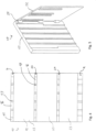
- FIG. 1 shows a view of a wall component 10 from the perspective of a building interior G (see 2 ) Standing viewer, wherein the wall component 10 has a base plate 11 and a cover 12.
- the base plate 11 forms a wall plate and runs vertically, in particular between an in 2 only schematically indicated floor B of the building interior G in the form of a slab-shaped floor covering and a likewise only schematically indicated ceiling D of the building interior G.
- the base plate 11 consists in particular of concrete or masonry and has an inner surface 13 facing the building interior G and an outer surface facing away from the building interior G 14 on.
- the base plate 11 is shown as a load-bearing wall part, which optionally also fulfills an insulating function.
- configurations are conceivable in which the base plate 11 is designed as a cover shell and is arranged in addition to an already existing load-bearing wall part. In this case, the base plate 11 has no supporting function.
- the base plate 11 On its inner surface 13, the base plate 11 is provided with a profile 15 of vertical channel-like grooves 16, which are arranged horizontally offset at a distance next to each other, run parallel to one another and each have a rectangular cross section. Each two adjacent grooves 16 are separated from one another by a web 17, with all webs 17 also running vertically and being arranged parallel to one another. Both the grooves 16 and the webs 17 extend over the entire vertical height of the base plate 11 and form flow channels, in particular for air. In addition, the webs 17 have a smaller horizontal width than the grooves 16 . Together with the cover 12, the grooves 16 are designed as flow channels.
- the cover 12 is plate-shaped, oriented vertically, and placed and held on the inner surface 13 of the base plate 11 .
- the cover 12 ends in front of the lower edge of the base plate 11 at a distance S a , so that a lower exposed inflow area a is formed.
- the cover 12 ends in front of the upper edge of the base plate 11 at a distance s b , so that an upper, exposed outflow area b is formed.
- the lower, exposed inflow area a and the upper, exposed outflow area b of the base plate 11 are not covered by the cover 12 and are exposed to the interior G of the building.
- the exposed lower inflow area a of the base plate 11 extends from the lower edge of the cover 12 to the lower edge of the base plate 11 over its entire width and has a vertical height s a in the range from 0.05 m to 0.50 m, preferably from 0 .10 m to 0.50 m.
- the exposed upper outflow region b of the base plate 11 extends from the upper edge of the Cover 12 to the top edge of base plate 11 over a vertical height s b in the range 0.05m to 0.30m and preferably 0.05m to 0.15m.
- the grooves 16 are exposed to the building interior G and in this way form inlet openings 18 in the lower inflow area a for air flowing into the wall component 10, which flows vertically upwards in the flow channels of the wall component 10 and emerges from the upper outflow area b, so that the grooves 16 there form outlet openings 19 .
- the cover 12 has the same horizontal width as the base plate 11 and a reduced vertical height in comparison.
- An inner surface 20 of the cover 11 faces the building interior G, an outer surface 21 of the cover 12 faces the base plate 11 .
- the cover 12 is preferably releasably attached and held to the inner surface 13 of the base plate 11 by its outer surface 21 .
- In 2 is the section II-II of the wall member 10 according to 1 shown.
- the floor B of the building interior G is only indicated by dashed lines and closes flush, preferably with the interposition of a seal 51 (see Fig. 13 ) with the lower edge of the cover 12, so that the lower inflow area a of the base plate 11 with the inlet openings 18 is arranged below the upper side of the base B.
- the ceiling D is flush with the upper edge of the base plate 11, so that the upper outflow area b of the base plate 11 and also the upper edge of the cover 12 are arranged below the ceiling.
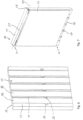
- FIG. 3 shows the wall component 10 with the base plate 11 and the cover 12 in an exploded view.
- the horizontal outer grooves 16 of the base plate 11 each have a notch 36 in the upper area, so that in the upper area of the outer grooves 16 a widening of the cross section with a console-like gradation 37 is formed.
- the cover 12 shown on the right has strip-like vertical projections 22 on its outer surface 21 which extend over the upper half of the cover 12 .
- the projections 22 are arranged parallel to one another and offset horizontally next to one another.
- the thickness of the projections 22 corresponds substantially to the depth of the grooves 16 of the base plate 11.
- adhesives and/or sealants can be applied to the console-like gradations 37 and the web ends of the cover and/or at contact points of grooves in the base plate and webs of the cover.
- a wall component 10 with a base plate 11 and a multi-part cover 12 is shown.
- the base plate 11 corresponds to the embodiment already described.
- the cover 12 has three cover parts 23 which are arranged vertically one above the other and at a distance parallel to one another, in each case transversely, which are spaced apart from one another in the vertical direction, so that intermediate spaces 24 running horizontally are formed between them.
- the grooves 16 of the base plate 11 are exposed towards the building interior G, so that central outflow openings for air are formed from the flow channels formed by the grooves 16 with the cover 12.
- the lower inflow area a and the upper outflow area b of the base plate 11 are also exposed towards the building interior G, as has already been described above.
- FIG 5 shows a further development of the wall component 10 according to FIG 3 , wherein the cover 12 is hinged to the base plate 11 via three vertically stacked hinges on the right side of the base plate 11.
- the cover 12 is thus pivotable relative to the base plate 11 like a door, with the hinges 25 serving as fulcrums.
- the hinges 25 fulfill a holding function for the cover 12.
- the hinges 25 are designed, for example, as door hinges, ie multi-part hinges such as are used in doors in particular. Part of a door hinge is on the base plate 11 fixed while the other part of the hinge is connected to the cover 12.
- the base plate 11 has the already mentioned profiling 15 with vertical grooves 16 and webs 17 .
- the horizontally outer grooves 16 are not stepped, but have a cross section that remains constant over the vertical length.
- All webs 17 are provided with a rectangular recess 26 at approximately the middle height of the base plate 11, all recesses 26 being configured as transverse grooves on the inner surface 13 of the base plate 11.
- the recesses 26 of the horizontally outer profile webs 17 on the left and right do not extend over the entire width of the respective webs 17.
- the recesses 26 of the inner webs 17 extend over their entire width, so that adjacent grooves 16 over the recesses 26 are connected to each other.
- the depth of the recesses 26 is less than the depth of the grooves 16, so that the bottoms of the recesses 26 protrude beyond the grooves 16.
- This configuration makes it possible, for example, to attach a transverse bar (not shown) in the transverse groove formed by all of the recesses 26, which is held vertically in the recesses 26 and fixed horizontally by the respective outer profile webs 17.
- the crossbar may be attached to the cover 12 such that the cover 12 is accurately and securely positioned relative to the base plate 11 by engagement of the crossbar in the recesses 26 .
- the crossbeam can be part of a carrier system which, in addition to the crossbeam, has further mounting elements and which connects the cover 12 to the base plate 11, for example by means of hooks/clamps which enclose the base plate 11 when the cover 12 is in the fastened state.
- the wall component 7 shows a further embodiment of the wall component 10, which has a strip-like horizontal projection 27 in the upper outflow area of the base plate 11, the projection 27 serving as an air guiding element.
- the horizontal width of the projection 27 corresponds to the width of the base plate 11, so that the projection 27 is flush with the base plate 11 horizontally.
- the strip-like projection 27 cantilevers into the building interior G with a cantilever length that is greater than the thickness of the cover 12, so that the projection 27 projects beyond the cover 12 and covers it at a distance.
- the projection 27 is a sheet metal or a plastic part.
- the cover 12 has, in a manner already explained ( 1 ) A lower height than the base plate 11, so that the lower inflow area a and the upper outflow area b of the base plate 11 to the building interior G are exposed.
- the upper outflow area b of the base plate 11 is provided with a horizontal joint 28 which is arranged between the upper edge of the cover 12 and the projection 27 and connects the flow channels formed by the grooves 16 to one another.
- the horizontal width of the joint 28 corresponds to the width of the base plate 11, so that the joint 28 is flush with the base plate 11 horizontally.
- the depth of the joint 28 corresponds to the depth of the grooves 16, being between the grooves 16 and the joint 28 a flush transition is designed.
- the joint 28 can serve as an installation duct, for example in that a horizontally running line 29 is arranged in the joint 28 and runs through the base plate 11 .
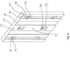
- FIG. 8 shows a base plate 11 with several alternative and detachable attachment options for the cover 12:
- two vertically offset brackets 30 which run parallel to one another and are U-shaped and have a transverse web 32 serving as a base and two legs.
- the brackets 30 are made of metal, for example, and are connected with their limbs to the base plate 11 and, in particular, cast into it.
- a lateral recess 31 is provided on the webs 17 of the base plate 11, so that the cross section of the groove 16 in the area of the brackets 30 is widened horizontally.
- the transverse webs 32 terminate flush with the webs 17 on the inner surface 13 of the base plate 11 facing the interior G of the building.
- the cover 12 is provided with hook-like projections (not shown) on its outer surface 21, which engage in a form-fitting manner in the spaces between the brackets 30 between the transverse webs 32 and the bottom of the groove 16.
- the middle web 17 of the base plate 11 has two first depressions 33 arranged vertically one above the other and having a rectangular base area.
- the depth of the first Indentation 33 corresponds approximately to the depth of groove 16.
- a second indentation 34 with a rectangular base area is formed eccentrically and vertically upwards in the bottom of first indentation 33.
- the outer surface 21 of the cover 12 is provided with projections (not shown), the shape of which is designed to complement the indentations 33, 34 so that the projections fit snugly into the depressions 33, 34 can be used and cant and wedge there. As a result, the tilting moment of the cover 12 is absorbed and the cover 12 is held on the base plate 11 .
- the left-hand groove 16 of the base plate 11 is provided with two recesses 35 arranged vertically one above the other. Formed in the bottom of each recess 35 are two vertical, spaced apart engagement slots 38 which may have undercuts.
- projections are formed on the outer surface 21 of the cover 12 and can have a hook-like configuration. When the cover 12 is fastened, the projections engage in the engagement slots 35 of the recesses 35 , as a result of which they are wedged in them and the cover 12 is connected to the base plate 11 .
- 9 12 shows a holding part 48a which can be attached to the cover 12 and on the outer surface 21 of which two projections 39 are formed which run vertically and parallel to one another and are arranged at a distance from one another. Both protrusions 39 have each according to 9 a recess 40 in the lower area.
- the projections 39 can be connected to the in 8 shown indentations 33, 34 of the base plate 11 are preferably engaged with a close fit. In this way, the cover 12 is wedged to the base plate 11 and held.
- 10 shows another mounting option between the base plate 11 and the cover 12.
- the holding part 48b shown on the left is attached to the cover 12 and is provided with the projections 39 and recesses 40 already mentioned.
- a triangular nose 41 is formed on the projections 39, the tip of which is directed downwards.
- the holding part 48c shown on the right is arranged on the base plate 11 and has two projections 42 arranged parallel and spaced apart from one another in the lower area.
- the projections 42 extend only up to the middle height of the holding part 48c.
- a triangular depression 43 is formed on the upper side of the projections 42, the tip of which points downwards.
- the indentations 43 are shaped complementarily to the lugs 41 of the retaining portion 48b of the cover 12 so that the indentations 43 and the lugs 41 are engageable with a close fit.
- a holding part 48d of the base plate 11 which has a depression 44 with a rectangular cross section, in which a carriage 45 is mounted in a linearly displaceable manner.
- the carriage 45 is cuboid, so that it can be moved horizontally in the depression 44 . with his upper End face 46, the carriage 45 protrudes beyond the upper end face 50 of the holding part 48d.
- the cover 12 is provided with at least one lug (not shown) which is shaped complementarily to the indentation 47 of the carriage 45, so that the lug of the cover 12 can be fitted with the indentation 47 of the carriage 45, for example with a close fit in intervention can be brought.
- the cover 12 is hooked into the notches 47 of the carriages 45 and is held by them. Due to the mobility of the carriage 45, the cover 12 can be moved and adjusted in the horizontal direction in the held state.
- FIG. 12 shows another holding part 48e of the base plate 11, which has two projections 52 at its two horizontal ends, which delimit a recess 53 between them. Both projections 52 run perpendicularly over the entire vertical height of the holding part 48e and parallel to one another.
- the recess 53 between the two projections 52 has at its bottom a triangular profile 54 in cross section, which is periodically continued in the vertical direction over the entire height of the holding part 48e.
- the cover 12 is provided with a projection (not shown) which has a complementary shape corresponding to the profiling 54 of the holding part 48e and which in particular has a corrugated or triangular shape in cross section.
- the cover 12 is against Base plate 11 tensioned, so that the projection of the cover 12 protrudes into the profile 54 of the holding part 48e of the base plate 11 and is held in a form-fitting manner.
- the projection can optionally engage in one of the indentations of the profile, so that the holding part 48e corresponds to a vertically stepped positioning aid. Unintentional horizontal movements of the cover 12 during attachment are avoided due to the projections 52 of the holding part 48e as soon as the projection of the cover 12 protrudes into the recess 53 of the holding part 48e.
- adhesives and/or sealants can be applied to the bracket-like gradations 37 and the web ends of the cover and/or at contact points of grooves in the base plate and webs of the cover.
- the wall component 10 is particularly suitable as a component of a room heating system, with the lower inflow area a of the in 1 shown wall component 10 warm air can be introduced from an air source, which then flows within the flow channels formed by the grooves 16 upwards. At the upper outflow area b of the base plate 11, the air can escape from the flow channels to the interior G of the building. In the same way, stale air from the building interior G can be sucked down through the grooves 16 and discharged.
- the cover 12 is detachably connected to the base plate 11, the movement of the air being unhindered by the type of attachment.
- the configuration of the base plate 11 and the cover 12 also allows the geometries of the grooves 16 and the flow channels to be changed: In the 3 shown embodiment of the wall member 10 can through the projections 22 on the outside 21 of the cover 12 individual or all grooves 16 of the base plate 11 are closed or narrowed.
- the projection 27 of the in 7 The wall component 10 shown forms a guide element for the air flowing out of the grooves 16, so that the outlet of the air is directed into the building interior G and made more uniform.
- Lines 29 can be arranged both in the grooves 16 and in the joint 28, in particular when the wall component 10 is operated as a space heater.
- the 13, 14 and 15 show another embodiment of the wall component 10 with a base plate 11 and a cover 12 schematically in cross section.
- the cover 12 is arranged at a distance from the base B and a seal 51 closes the space between the cover 12 and the base B in a fluid-tight manner.
- the floor B is arranged at a vertical distance from a subsurface U, so that an intermediate space is formed below the floor B, in which air can be supplied or discharged.
- the base plate 11 stands on the ground U, while the cover 12 is in contact with the floor B via the seal 51 .
- the area of the base plate 11 between the floor B and the subsurface U is the already mentioned lower inflow area a.
- the wall component 10 is shown as a component of a room heating system: warm air flows in the space between the floor B and the subsoil U onto the wall component 10, which is shown by the dashed line.
- the warm air enters the lower inflow area a of the base plate 11 into the grooves 16 and rises within the flow channels upwards.
- the seal 51 between the cover 12 and the base B prevents the warm air from escaping between the cover 12 and the base B, so that the warm air continues to rise within the flow channels.
- Out of 13 shows that the cover 12 does not completely cover the base plate 11 and the already mentioned upper outflow area b of the base plate 11 towards the building interior G is exposed.
- the upper outflow area b is formed between the ceiling D and the upper edge of the cover 12 .
- the warm air that rises within the flow channels exits from the grooves 16 of the base plate 11 in the upper outflow area b and is conducted into the interior G of the building.
- used air from the building interior G can be sucked in in the upper outflow area b and guided down the flow channels until the used air emerges in the lower inflow area a and can be discharged via the space between the floor B and the subsurface U.
- the 15 shows a further embodiment of the wall component 10, in which the above-mentioned projection 27 is formed in the joint 28 in the upper outflow area b of the base plate 11 (see Fig. 7 ) and horizontal or perpendicular to the plane of the 15 runs.
- the projection 27 is designed as a strip-shaped profile piece made of metal or plastic and serves as an air guiding element for the warm air flowing from the flow ducts to the interior G of the building.
- the projection 27 can be designed in several parts, with at least one of the parts of the projection 27 being movable, for example pivotable about a horizontal axis, see above that the angle of inclination of the projection 27 with respect to the ceiling D is adjustable.
- the exit angle of the hot air guided through the grooves 16 of the base plate 11 into the building interior G can be changed.
- the projection 27 can be adjusted manually or by motor. With an exit angle relative to the ceiling D of 0°, as in 15 shown, the projection 27 is located directly on the ceiling. At an exit angle of 90°, the projection 27 assumes a closed position in which it closes the upper outflow area b of the base plate 11 .
Landscapes
- Engineering & Computer Science (AREA)
- Architecture (AREA)
- Mechanical Engineering (AREA)
- General Engineering & Computer Science (AREA)
- Structural Engineering (AREA)
- Thermal Sciences (AREA)
- Physics & Mathematics (AREA)
- Civil Engineering (AREA)
- Life Sciences & Earth Sciences (AREA)
- Sustainable Development (AREA)
- Chemical & Material Sciences (AREA)
- Combustion & Propulsion (AREA)
- Finishing Walls (AREA)
- Ventilation (AREA)
Description
- Die Erfindung betrifft eine Wandheizung gemäß dem Oberbegriff des Anspruchs 1.
- Ein derartiges Wandbauteil wird genutzt, um Luft einer Luftquelle innerhalb eines Gebäudes durch dessen Wände zu Gebäudeinnenräumen zu leiten. Die Nut der Profilierung einer Grundplatte bildet mit der an der Grundplatte befestigten Abdeckung einen Strömungskanal.
- Gattungsgemäße Wandbauteile haben den Nachteil, dass der Zugang von Luft zu den Strömungskanälen im Inneren des Wandbauteils nur mittels einer Bearbeitung der Abdeckung erfolgen kann, beispielsweise durch Durchbohren der Abdeckung, bis eine Verbindung vom Gebäudeinnenraum zum Strömungskanal geschaffen ist. Dieses Vorgehen ist mühsam und zeitaufwändig und es besteht die Gefahr von Verunreinigungen der Strömungskanäle, wobei Verunreinigungen aufgrund der Luftumwälzung in den Gebäudeinnenraum oder in Betriebseinrichtungen gelangen können. Der Verwendungszweck des Wandbauteils insbesondere im Rahmen einer Wandheizung ist daher stark eingeschränkt.
- Aus der
EP 2 681 493 A1 ist eine Wandheizung mit einem Wandbauteil bekannt, in das ein Heizköper integriert ist. Das Wandbauteil besitzt eine Grundplatte und eine auf der Grundplatte aufsetzbare Abdeckung. Im unteren Bereich sind in der Abdeckung mehrere Einströmöffnungen ausgebildet, durch die die zu erwärmende Luft aus dem Innenraum eines Gebäudes dem innerhalb des Wandbauteils angeordneten Heizkörper zuführbar ist. Die durch den Heizkörper erwärmte Luft steigt innerhalb des Wandbauteils auf und tritt an mehreren im oberen Bereich der Abdeckung ausgebildeten Ausströmöffnungen aus. Da der Heizkörper in das Wandbauteil fest integriert ist, ist das Wandbauteil konstruktiv aufwendig und benötigt eine zeitintensive Montage. - Einen grundsätzlich gleichen Aufbau einer Wandheizung zeigt auch die
WO 2013/087952 A1 , wobei zusätzlich eine Vielzahl von Luftleitelementen innerhalb des Wandbauteils vorgesehen sind. - Die
EP 2 423 398 A1 zeigt eine isolierende Vorsatzschale für eine Bauteilwand, wobei die Vorsatzschale so angeordnet ist, dass zwischen der Vorsatzschale und der Bauteilwand ein Hinterlüftungsraum gebildet ist, der von Luft durchströmt ist. Eine Wandheizung ist gemäß derEP 2 423 398 A1 nicht vorgesehen. - Aus der
US 3,303,770 A ist ein Gebäude bekannt, bei dem der Boden, die Wände und die Decke jeweils doppelwandig ausgebildet sind und Luftkanäle bilden, so dass die Luft in einem geschlossenem Kreislauf zirkulieren kann. - Es ist die Aufgabe der Erfindung, eine Wandheizung so weiterzubilden, dass ein einfacher und effizienter Zugang und Abgang von Luft zum Strömungskanal des Wandbauteils möglich ist.
- Die erfindungsgemäße Aufgabe wird gelöst mittels einer Wandheizung mit den Merkmalen des Anspruchs 1. Die Wandheizung besitzt eine Luftquelle und es ist ein Boden bzw. Bodenbelag und ein unterhalb des Bodens oder Bodenbelags angeordneter Untergrund vorhanden. Auch dabei ist ein Wandbauteil vorgesehen, bei dem die Abdeckung mit einem Abstand von der unteren Kante der Grundplatte unter Bildung eines unteren frei liegenden Einströmbereichs der Grundplatte endet, wobei die Abdeckung mit einem Abstand von der oberen Kante der Grundplatte und der Bildung eines oberen frei liegenden Ausströmbereichs der Grundplatte endet und wobei die Nut zusammen mit der Abdeckung einen Strömungskanal ausbildet, der den unteren frei liegenden Einströmbereich und den oberen freiliegenden Ausströmbereich verbindet. Zwischen dem Bodenbelag und dem Untergrund ist ein Zwischenraum ausgebildet, in den Luft von der Luftquelle einleitbar ist und wobei die Luft durch den unteren frei liegenden Einströmbereich in den mindestens einen Strömungskanal einbringbar, entlang dem mindesten einen Strömungskanal strömbar und an den oberen frei liegenden Ausströmbereich der Grundplatte ausströmbar und in den Gebäudeinnenraum einbringbar ist.
- Eine Grundüberlegung ist, dass der Zugang von Luft zu dem Strömungskanal des Wandbauteils mittels der Dimensionierung der Abdeckung möglich ist. Aufgrund der Tatsache, dass die Abdeckung die Grundplatte nicht vollständig überdeckt, insbesondere im unteren und oberen frei liegenden Ein- und Ausströmbereich der Grundplatte, liegt die Nut der Grundplatte in diesen Bereichen zum Zwischenraum bzw. zum Gebäudeinnenraum hin offen, so dass Luft in diesen Bereichen in die Nuten ein- bzw. ausströmen kann. Der Strömungskanal des Wandbauteils verbindet den Einströmbereich mit dem Ausströmbereich.
- Durch die Ausgestaltung des Wandbauteils entfällt insbesondere die Notwendigkeit einer nachträglichen Bearbeitung des Wandbauteils und insbesondere dessen Abdeckung. Damit werden Verunreinigungen des Strömungskanals und insbesondere des Gebäudeinnenraums vermieden. Darüber hinaus sind keine zusätzlichen Bauteile wie Rohre, Stutzen, Manschetten oder dergleichen notwendig.
- Mehrere Grundplatten können von einer Abdeckung überdeckt werden. Dies ist insbesondere dann sinnvoll, wenn eine Wand des Gebäudeinnenraums durch mehrere Grundplatten ausgestaltet werden soll, deren Dimension vorbekannt ist. Sämtliche Grundplatten können dann von einer einzigen Abdeckung überdeckt werden, was einer Einsparung von Material und Aufwand entspricht.
- Darüber hinaus kann eine Grundplatte von mehreren Abdeckungen überdeckt sein. Dies ist insbesondere dann vorteilhaft, wenn zu dekorativen Zwecken eine bestimmte Anordnung von Abdeckungen auf der Grundplatte gewünscht ist. In diesem Fall sind beispielsweise auch Leitungen in die Zwischenräume zwischen mehreren Abdeckungen einbringbar.
- Die Profilierung auf der Innenoberfläche der Grundplatte weist vorzugsweise neben der mindestens einen Nut mindestens einen Steg auf, insbesondere an den horizontal jeweils äußeren Kanten der Grundplatte. Die Stege begrenzen die Nuten und können insbesondere zur Abgrenzung von mehreren Nuten untereinander ausgestaltet sein. Vorzugsweise weist die Profilierung der Grundplatte Nuten und Stege in horizontal alternierender Anordnung auf.
- Der Querschnitt der Nut oder der Nuten sollte über die gesamte Länge konstant sein. Alternativ kann vorgesehen sein, dass der Querschnitt der mindestens einen Nut sich verändert, wobei insbesondere die mindestens eine Nut mindestens eine Ausklinkung aufweisen kann. Die mindestens eine Nut bildet zusammen mit der Abdeckung den mindestens einen Strömungskanal zum Transport der Luft. Durch eine Veränderung des Querschnitts kann daher Einfluss auf die Strömungsdynamik der Luft genommen werden. So kann insbesondere eine bestimmte Nut verschließbar sein, um eine Strömung von Luft innerhalb dieser Nut bzw. des entsprechenden Strömungskanals zu unterbinden.
- Gemäß der Erfindung ist der untere frei liegende Einströmbereich der Grundplatte unterhalb des Bodens oder Bodenbelags des Gebäudeinnenraums angeordnet. Im Sinne der Erfindung bezeichnet der Bodenbelag die dem Gebäudeinnenraum zugewandte obere Schicht des Bodens oder den oberen Konstruktionsbereich eines Bodenaufbaus, beispielsweise eines Fußbodens. Auf diese Weise kann Luft durch den Zwischenraum zwischen dem Bodenbelag und dem unterhalb des Bodenbelags angeordneten Untergrund zum unteren frei liegenden Einströmbereich der Grundplatte gelangen. Vorzugsweise ist eine Dichtungsvorrichtung zwischen der Abdeckung und dem Bodenbelag angeordnet, so dass ein Austausch von Luft unterhalb der Abdeckung im unteren frei liegenden Einströmbereich der Grundplatte zum Gebäudeinnenraum unterbunden ist.
- Der obere freiliegende Ausströmbereich der Grundplatte kann unterhalb der Decke des Gebäudeinnenraums angeordnet sein. Insbesondere kann die Decke in unmittelbarem Kontakt mit der oberen Kante der Grundplatte stehen. Auf diese Weise ist ein Luftaustausch in einem Bereich oberhalb der Decke unterbunden.
- Vorzugsweise ist die mindestens eine Nut vertikal und geradlinig ausgerichtet, was im Zusammenhang mit der Abdeckung eine besonders einfache Ausgestaltung des Strömungskanals darstellt. Darüber hinaus kann auch der mindestens eine Steg der Profilierung vertikal und geradlinig ausgerichtet sein.
- In einer weiteren Ausgestaltung der Erfindung kann eine Vielzahl von parallel zueinander verlaufenden Nuten vorgesehen sein, was einer besonders einfachen Anordnung mehrerer Nuten entspricht. Darüber hinaus können auch die Stege der Profilierung der Grundplatte parallel zueinander verlaufen und insbesondere auch parallel zu den Nuten ausgerichtet sein.
- Vorzugsweise ist vorgesehen, die Abdeckung mit Oberflächenbereichen der Grundplatte beispielsweise in den Kontaktbereichen zwischen den Stegen und der Abdeckung mittels eines und/oder dichtenden Haftmittels verbunden ist.
- Vorzugweise ist vorgesehen, dass die Abdeckung an der Innenoberfläche der Grundplatte lösbar befestigt ist. Auf diese Weise ist ein schneller Zugriff auf die Nuten der Grundplatte möglich, wie auch ein Austausch der Abdeckung. Die lösbare Befestigung der Abdeckung an der Grundplatte kann mittels Kraft- und/oder Formschluss erfolgen. Zu diesem Zweck können Halteteile an der Grundplatte und/oder an der Abdeckung vorgesehen sein. Beispielsweise ist die Abdeckung mit hakenartigen Halteteilen versehen, die mit U-förmigen Bügeln auf der Innenseite der Grundplatte in Eingriff bringbar sind. Auf diese Weise wird das Kippmoment der Abdeckung von der Grundplatte aufgenommen und damit die Abdeckung an der Grundplatte gehalten. Zu diesem Zweck können die Halteteile mit Vorsprüngen und Ausnehmungen versehen sein, die miteinander in Eingriff bringbar sind. Vorzugsweise sind zusätzlich Hinterschneidungen vorgesehen.
- Die an der Grundplatte lösbar befestigte Abdeckung kann horizontal und/oder vertikal beweglich sein. Dies kann beispielsweise mittels verschiebbarer Schlitten an der Abdeckung und/oder an der Grundplatte verwirklicht sein, beispielsweise Axialschlitten. Vorzugsweise sind die Schlitten an den Halteteilen angebracht.
- Darüber hinaus kann die vorzugsweise lösbare Befestigung der Abdeckung an der Grundplatte mittels Positionierhilfen erfolgen, die insbesondere horizontal und/oder vertikal abgestuft und die vorzugsweise an den Halteteilen angebracht sind. Auf diese Weise ist eine Befestigung der Abdeckung an der Grundplatte in reproduzierbaren Positionen gewährleistet. Dies kann beispielsweise über Halteteile an der Abdeckung und/oder der Grundplatte verwirklicht werden, die eine abgestufte Profilierung aufweisen, in die Vorsprünge an definierten Stellen in Eingriff bringbar sind.
- Vorzugsweise ist vorgesehen, dass auf der Innenoberfläche der Grundplatte mindestens eine Quernut vorgesehen ist, mit der ein Trägersystem zur Aufnahme der Abdeckung in Eingriff bringbar ist. Die Quernut kann beispielsweise als mindestens eine Ausnehmung auf dem mindestens einen Steg der Profilierung der Grundplatte ausgestaltet sein. Vorzugsweise sind sämtliche Stege mit jeweils einer Ausnehmung versehen.
- Das Trägersystem weist beispielsweise einen Querbalken auf, der mit der mindestens einen Quernut in Eingriff bringbar ist und insbesondere darin gehalten ist. Darüber hinaus kann das Trägersystem weitere Halteteile aufweisen zur form- bzw. kraftschlüssigen und lösbaren Halterung der Abdeckung an der Grundplatte. Beispielsweise können die Halteteile in befestigtem Zustand der Abdeckung an der Grundplatte letztere umgreifen.
- Die mindestens eine Abdeckung kann mehrteilig ausgestaltet sein, wobei insbesondere jedes Abdeckteil mit Halteteilen zur lösbaren Befestigung des Abdeckteils an der Grundplatte versehen ist. Ist beispielsweise der Zugang nur zu einem kleinen Bereich eines Strömungskanals gewünscht, entfällt die Notwendigkeit, die gesamte Abdeckung zu lösen, sondern es in diesem Fall muss nur ein spezifisches Abdeckteil gelöst werden.
- Mindestens zwei benachbarte Abdeckteile der mindestens einen Abdeckung können mit gegenseitigem Abstand parallel zueinander angeordnet sein und zwischen sich einen Zwischenraum bilden, so dass eine mittlere Austrittsöffnung des Strömungskanals ausgebildet ist. Die Abdeckteile können insbesondere vertikal übereinander angeordnet sein, so dass der die mindestens eine mittlere Austrittsöffnung des Strömungskanals bildende Zwischenraum horizontal ausgerichtet ist. Dabei kann Luft im Strömungskanal des Wandbauteils durch die mittlere Austrittsöffnung in den Gebäudeinnenraum gelangen.
- In einer alternativen Ausgestaltung ist die Abdeckung schwenkbar an der Grundplatte angeordnet, insbesondere schwenkbar um eine vertikale Achse. Auf diese Weise kann die Abdeckung einfach mit der Grundplatte verbunden und wieder gelöst werden. Beispielsweise kann dies mittels Scharnieren verwirklicht sein, insbesondere mittels Türangeln, wobei ein Teil einer Türangel an der Abdeckung und der andere Teil der Türangel an der Grundplatte befestigt ist.
- In vorteilhafter Ausgestaltung erstreckt sich der untere frei liegende Einströmbereich der Grundplatte über die gesamte Breite der Grundplatte und weist eine vertikale Höhe im Bereich von 0,05 m bis 0,50 m, vorzugweise von 0,10 m bis 0,50 m auf. Sämtliche Strömungskanäle des Wandbauteils sind auf diese Weise für Luft aus dem Zwischenraum zwischen dem Boden bzw. Bodenbelag und dem Untergrund zugänglich. Der untere Einströmbereich ist groß genug, um eine problemlose Zufuhr von Luft zum Strömungskanal zu gewährleisten.
- Der obere frei liegende Ausströmbereich der Grundplatte kann sich über die gesamte Breite der Grundplatte erstrecken und eine vertikale Höhe von 0,05 m bis 0,30 m, vorzugsweise von 0,05 m bis 0,15 m aufweisen. Auf diese Weise kann Luft von dem Strömungskanal über den oberen Ausströmbereich der Grundplatte hin zum Gebäudeinnenraum fließen. Insbesondere ist die vertikale Höhe des unteren frei liegenden Einströmbereichs grösser als die vertikale Höhe des oberen frei liegenden Ausströmbereichs der Grundplatte.
- Die Grundplatte kann als tragendes Bauteil ausgestaltet sein, wobei tragend im Sinne der Erfindung bedeutet, dass das Bauteil neben seinem Eigengewicht auch zur Aufnahme von Lasten aus der Gebäudenutzung und/oder aus darüber liegenden Bauteilen, beispielsweise Decken, ausgestaltet ist. Auf diese Weise entfällt die Notwendigkeit für zusätzliche tragende Bauteile für den Gebäudeinnenraum, wodurch Material und Aufwand eingespart werden kann.
- Alternativ dazu kann die Grundplatte auch als Vorsatzschale für ein tragendes Wandbauteil ausgestaltet sein. In diesem Fall ist die Grundplatte ein nicht tragendes Bauteil, so dass die Grundplatte lediglich ihr Eigengewicht aufnimmt. In diesem Fall können bereits bestehende Gebäudeinnenräume mit tragenden Wandbauteilen durch das erfindungsgemäße, nicht tragende Wandbauteil nachgerüstet werden.
- Vorzugweise ist ein leistenartiger Vorsprung als Luftleitelement im oberen frei liegenden Ausströmbereich an der Grundplatte angeordnet. Als Luftleitelement dient der Vorsprung zur Richtung und Vergleichmäßigung der aus dem oberen frei liegenden Ausströmbereich in dem Gebäudeinnenraum eingeleiteten Luft. Dabei kann sich der leistenartige Vorsprung über die gesamte horizontale Breite der Grundplatte erstrecken, so dass der Vorsprung mit der Grundplatte horizontal bündig abschliesst. Zusätzlich oder alternativ dazu kann der Vorsprung kragend in Richtung des Gebäudeinnenraums ausgestaltet sein, so dass der Vorsprung die Abdeckung überragt. Auf diese Weise ist eine leichtere Richtung der in den Gebäudeinnenraum strömenden Luft möglich.
- Im Bereich zwischen dem leistenartigen Vorsprung und der Abdeckung kann die Grundplatte mit einer Fuge an der Innenoberfläche versehen sein. Die Breite der Fuge entspricht vorzugsweise der horizontalen Breite der Grundplatte, so dass die Fuge horizontal mit der Grundplatte bündig abschließt. Die Tiefe der Fuge kann der Tiefe der mindestens einen Nut entsprechen, so dass ein bündiger Übergang zwischen der mindestens einen Nut und der Fuge ausgestaltet ist. Durch die Fuge wird eine weitere Vergleichmäßigung der aus den Strömungskanälen bzw. Nuten in den Gebäudeinnenraum einströmenden Luft ermöglicht. Weiterhin kann mindestens eine Leitung in der Fuge und/oder in der mindestens einen Nut der Grundplatte angeordnet sein. Auf diese Weise kann die Fuge wie auch die mindestens eine Nut zur Verlegung von Leitungen genutzt werden, was einen platzsparenden Aufbau mit sich bringt und einer einfachen Versorgung von Betriebseinrichtungen dient.
- Der Vorsprung kann verstellbar, insbesondere um eine horizontale Achse schwenkbar ausgestaltet sein. Auf diese Weise ist die Richtung der in den Gebäudeinnenraum einströmenden Luft veränderbar. Die Verstellbarkeit des Vorsprungs kann manuell und/oder motorisch erfolgen, wobei die motorische Verstellung zusätzlich fernsteuerbar sein kann. Damit kann die Richtung der in den Gebäudeinnenraum einströmenden Luft von einem Benutzer, in der Regel von einem Bewohner des Gebäudeinnenraums, verändert werden. In vorteilhafter Ausgestaltung kann der Vorsprung in Abhängigkeit von Parametern des Gebäudeinnenraums verstellbar sein, gemessen etwa mittels mindestens eines Sensors im Gebäudeinnenraum, wobei der Sensor mit dem Wandbauteil verbunden ist. Auf diese Weise ist eine automatische Ansteuerung des Vorsprungs möglich.
- Der Vorsprung kann in eine Schließposition bringbar sein, in der er den oberen Ausströmbereich der Grundplatte verschließt, so dass ein Austausch von Luft zwischen dem Gebäudeinnenraum und den Nuten bzw. den Strömungskanälen der Grundplatte unterbunden ist. Zu diesem Zweck kann das Wandbauteil im oberen Ausströmbereich der Grundplatte mindestens eine Dichtungsvorrichtung aufweisen. Die Dichtvorrichtung verbessert in Zusammenhang mit dem Vorsprung in seiner Schließposition die Dichtwirkung gegenüber dem Gebäudeinnenraum.
- Die Parameter der Wandheizung, wie beispielsweise Temperatur und/oder Strömungsgeschwindigkeit der in dem Gebäudeinnenraum einzuströmenden Luft können veränderbar sein, insbesondere in Abhängigkeit von mindestens einem in dem Gebäudeinnenraum angeordneten Sensor, der vorzugsweise mit der Wandheizung verbunden ist.
- Weitere Vorteile und Merkmale der Erfindung ergeben sich aus den Ansprüchen sowie aus der nachfolgenden Beschreibung, in der Ausführungsbeispiele der Erfindung unter Bezugnahme auf die Zeichnungen im Einzelnen erläutert sind. Dabei zeigen:
- Fig. 1
- eine Ansicht eines Wandbauteil mit einer Grundplatte und einer Abdeckung;
- Fig. 2
- den Schnitt II-II gemäß
Fig. 1 ; - Fig. 3
- das Wandbauteil gemäß
Fig. 1 in auseinander gezogener Darstellung; - Fig. 4
- ein Wandbauteil mit einer mehrteiligen Abdeckung;
- Fig. 5
- ein Wandbauteil mit angelenkter Abdeckung;
- Fig. 6
- eine Grundplatte in abgewandelter Ausführungsform;
- Fig. 7
- ein Wandbauteil gemäß einer Weiterbildung;
- Fig. 8
- eine Grundplatte mit mehreren Befestigungsvorrichtungen;
- Fig. 9,
- 10, 11 und 12 Halteteile zur Befestigung der Abdeckung an der Grundplatte
- Fig. 13
- eine Weiterbildung des Wandbauteils,
- Fig. 14
- eine Detailansicht des Wandbauteils gemäß
Fig. 13 und - Fig. 15
- eine Weiterbildung des Wandbauteils gemäß
Fig. 13 . -
Fig. 1 zeigt eine Ansicht eines Wandbauteils 10 aus der Perspektive eines in einem Gebäudeinnenraum G (s.Fig. 2 ) stehenden Betrachters, wobei das Wandbauteil 10 eine Grundplatte 11 und eine Abdeckung 12 aufweist. - Die Grundplatte 11 bildet eine Wandscheibe und verläuft vertikal insbesondere zwischen einem in
Fig. 2 nur schematisch angedeuteten Boden B des Gebäudeinnenraums G in Form eines plattenförmigen Bodenbelags und einer ebenfalls nur schematisch angedeuteten Decke D des Gebäudeinnenraums G. Die Grundplatte 11 besteht insbesondere aus Beton oder Mauerwerk und weist eine zum Gebäudeinnenraum G gerichtete Innenoberfläche 13 und eine dem Gebäudeinnenraum G abgewandte Außenoberfläche 14 auf. Gemäß denFig. 1 und 2 ist die Grundplatte 11 als tragendes Wandteil dargestellt, das gegebenenfalls auch eine dämmende Funktion erfüllt. Alternativ dazu sind Ausgestaltungen denkbar, bei denen die Grundplatte 11 als Abdeckschale ausgebildet ist und zusätzlich zu einem bereits vorhandenen tragenden Wandteil angeordnet ist. In diesem Fall erfüllt die Grundplatte 11 keine tragende Funktion. - Auf ihrer Innenoberfläche 13 ist die Grundplatte 11 mit einer Profilierung 15 aus vertikalen kanalartigen Nuten 16 versehen, die horizontal versetzt auf Abstand nebeneinander angeordnet sind, parallel zueinander verlaufen und jeweils einen rechteckigen Querschnitt aufweisen. Jeweils zwei benachbarte Nuten 16 sind durch einen Steg 17 voneinander getrennt, wobei sämtliche Stege 17 ebenfalls vertikal verlaufen und parallel zueinander angeordnet sind. Sowohl die Nuten 16 als auch die Stege 17 erstrecken sich über die gesamte vertikale Höhe der Grundplatte 11 und bilden Strömungskanäle insbesondere für Luft. Darüber hinaus weisen die Stege 17 eine geringere horizontale Breite als die Nuten 16 auf. Zusammen mit der Abdeckung 12 sind die Nuten 16 als Strömungskanäle ausgebildet.
- Die Abdeckung 12 ist plattenförmig ausgestaltet, vertikal ausgerichtet und auf der Innenoberfläche 13 der Grundplatte 11 angeordnet und gehalten. Die Abdeckung 12 endet vor der Unterkante der Grundplatte 11 mit einem Abstand Sa, so dass ein unterer frei liegender Einströmbereich a gebildet ist. Darüber hinaus endet die Abdeckung 12 vor der oberen Kante der Grundplatte 11 mit einem Abstand sb, so dass ein oberer frei liegender Ausströmbereich b gebildet ist. Der untere frei liegende Einströmbereich a und der obere frei liegende Ausströmbereich b der Grundplatte 11 sind nicht von der Abdeckung 12 überdeckt und liegen zum Gebäudeinnenraum G hin frei. Der frei liegende untere Einströmbereich a der Grundplatte 11 erstreckt sich von der Unterkante der Abdeckung 12 bis zur Unterkante der Grundplatte 11 über deren gesamte Breite und weist eine vertikale Höhe sa im Bereich von 0,05 m bis 0,50 m, vorzugsweise von 0,10 m bis 0,50 m auf. In gleicher Weise erstreckt sich der frei liegende obere Ausströmbereich b der Grundplatte 11 von der oberen Kante der Abdeckung 12 bis zur oberen Kante der Grundplatte 11 über eine vertikale Höhe sb im Bereich von 0,05 m bis 0,30 m und vorzugsweise von 0,05 m bis 0,15 m.
- Die Nuten 16 liegen im unteren Einströmbereich a und im oberen Ausströmbereich b jeweils zum Gebäudeinnenraum G frei und bilden auf diese Weise im unteren Einströmbereich a Eintrittsöffnungen 18 für in das Wandbauteil 10 einströmende Luft, die in den Strömungskanälen des Wandbauteils 10 in vertikaler Richtung nach oben strömt und aus dem oberen Ausströmbereich b austritt, so dass die dortigen Nuten 16 Austrittsöffnungen 19 bilden.
- Die Abdeckung 12 weist die gleiche horizontale Breite wie die Grundplatte 11 und eine demgegenüber verringerte vertikale Höhe auf. Eine Innenoberfläche 20 der Abdeckung 11 ist dem Gebäudeinnenraum G zugewandt, eine Außenoberfläche 21 der Abdeckung 12 ist der Grundplatte 11 zugewandt. Die Abdeckung 12 ist vorzugsweise lösbar mit ihrer Außenoberfläche 21 auf der Innenoberfläche 13 der Grundplatte 11 befestigt und an dieser gehalten.
- In
Fig. 2 ist der Schnitt II-II des Wandbauteils 10 gemäßFig. 1 dargestellt. Der Boden B des Gebäudeinnenraums G ist nur gestrichelt angedeutet und schließt bündig vorzugsweise unter Zwischenschaltung einer Dichtung 51 (s.Fig. 13 ) mit der unteren Kante der Abdeckung 12 ab, so dass der untere Einströmbereich a der Grundplatte 11 mit den Eintrittsöffnungen 18 unterhalb der Oberseite des Bodens B angeordnet ist. Die Decke D schließt bündig mit der oberen Kante der Grundplatte 11 ab, so dass der obere Ausströmbereich b der Grundplatte 11 und auch die obere Kante der Abdeckung 12 unterhalb der Decke angeordnet sind. Auf diese Weise ist es möglich, dass Luft und insbesondere Warmluft, die dem Zwischenraum zwischen dem Boden B und einem unterhalb des Bodens B angeordneten Untergrund U zugeführt wird, an den Eintrittsöffnungen 18 in die von der Abdeckung 12 abgedeckten Strömungskanäle der Grundplatte 11 einströmt, in diesen aufsteigt und am oberen Ende der Nuten 16 im Bereich der Austrittsöffnungen 19 aus dem oberen Ausströmbereich b austritt und in den Gebäudeinnenraum G einströmt. -
Fig. 3 zeigt das Wandbauteil 10 mit der Grundplatte 11 und der Abdeckung 12 in auseinander gezogener Darstellung. Die horizontal äußeren Nuten 16 der Grundplatte 11 weisen im oberen Bereich jeweils eine Ausklinkung 36 auf, so dass im oberen Bereich der äußeren Nuten 16 eine Querschnittsverbreitung mit einer konsolenartigen Abstufung 37 gebildet ist. - Die in
Fig. 3 rechts dargestellte Abdeckung 12 weist auf ihrer Außenoberfläche 21 leistenartige, vertikale Vorsprünge 22 auf, die sich über die obere Hälfte der Abdeckung 12 erstrecken. Die Vorsprünge 22 sind parallel zueinander und horizontal versetzt nebeneinander angeordnet. Die Dicke der Vorsprünge 22 entspricht im wesentlichen der Tiefe der Nuten 16 der Grundplatte 11. Wenn die Abdeckung 12 auf der Grundplatte 11 angeordnet bzw. an dieser befestigt ist, stützen sich die unteren Enden der äußeren leistenartigen Vorsprünge 22 auf den konsolenartigen Abstufungen 37 der äußeren Nuten 16 der Grundplatte 11 ab. Die mittleren leistenartigen Vorsprünge 22 greifen in die mittleren Nuten 16 der Grundplatte 11 so ein, dass eine horizontale Verschiebung der Abdeckung 12 relativ zu der Grundplatte 11 verhindert und die Abdeckung 12 in vorbestimmter Weise an der Grundplatte 11 positioniert ist. - Alternativ können an den Konsolenartigen Abstufungen 37 und den Stegenden der Abdeckung und/oder an Kontaktpunkten von Nuten der Grundplatte und Stegen der Abdeckung Klebstoffe und/oder Dichtstoffe eingebracht sein.
- In
Fig. 4 ist ein Wandbauteil 10 mit einer Grundplatte 11 und einer mehrteiligen Abdeckung 12 dargestellt. Die Grundplatte 11 entspricht der bereits beschriebenen Ausgestaltung. Die Abdeckung 12 weist drei vertikal übereinander und auf Abstand parallel zueinander jeweils quer angeordnete Abdeckteile 23 auf, die in vertikaler Richtung gegenseitig beabstandet sind, so dass zwischen ihnen horizontal verlaufende Zwischenräume 24 gebildet sind. In den Zwischenräumen 24 liegen die Nuten 16 der Grundplatte 11 zum Gebäudeinnenraum G hin frei, so dass mittlere Ausströmöffnungen für Luft aus den von den Nuten 16 mit der Abdeckung 12 gebildeten Strömungskanälen gebildet sind. Darüber hinaus sind auch der untere Einströmbereich a und der obere Ausströmbereich b der Grundplatte 11 zum Gebäudeinnenraum G hin frei gelegt, wie dies bereits oben beschrieben ist. -
Fig. 5 zeigt eine Weiterbildung des Wandbauteils 10 gemäßFig. 3 , wobei die Abdeckung 12 mit der Grundplatte 11 über drei vertikal übereinander angeordnete Scharniere an der rechten Seite der Grundplatte 11 gelenkig verbunden ist. Die Abdeckung 12 ist somit relativ zur Grundplatte 11 wie eine Tür schwenkbar, wobei die Scharniere 25 als Drehpunkte dienen. Darüber hinaus erfüllen die Scharniere 25 eine Haltefunktion für die Abdeckung 12. Die Scharniere 25 sind beispielsweise als Türangeln ausgestaltet, also mehrteilige Scharniere, wie sie insbesondere bei Türen eingesetzt werden. Ein Teil einer Türangel ist dabei an der Grundplatte 11 befestigt, während das andere Teil der Türangel mit der Abdeckung 12 verbunden ist. - Eine andere Weiterbildung der Grundplatte 11 ist in
Fig. 6 gezeigt. Die Grundplatte 11 weist die bereits erwähnte Profilierung 15 mit vertikalen Nuten 16 und Stegen 17 auf. Im Gegensatz zu der Grundplatte gemäßFig. 3 sind die horizontal äußeren Nuten 16 nicht abgestuft, sondern weisen einen über die vertikale Länge hin gleichbleibenden Querschnitt auf. - Sämtliche Stege 17 sind auf etwa der mittleren Höhe der Grundplatte 11 mit einer rechteckigen Ausnehmung 26 versehen, wobei sämtliche Ausnehmungen 26 als Quernut auf der Innenoberfläche 13 der Grundplatte 11 ausgestaltet sind. Die Ausnehmungen 26 der horizontal jeweils äußeren Profilstege 17 links und rechts erstrecken sich nicht über die gesamte Breite der jeweiligen Stege 17. Im Gegensatz dazu erstrecken sich die Ausnehmungen 26 der inneren Stege 17 über jeweils deren gesamte Breite, so dass benachbarte Nuten 16 über die Ausnehmungen 26 miteinander verbunden sind. Die Tiefe der Ausnehmungen 26 ist kleiner als die Tiefe der Nuten 16, so dass die Böden der Ausnehmungen 26 die Nuten 16 überragen. Durch diese Ausgestaltung ist es beispielsweise möglich, einen Querbalken (nicht dargestellt) in der von sämtlichen Ausnehmungen 26 gebildeten Quernut anzubringen, der vertikal in den Ausnehmungen 26 gehalten und horizontal durch die jeweils äußeren Profilstege 17 fixiert ist. Der Querbalken kann an der Abdeckung 12 angebracht sein, so dass die Abdeckung 12 relativ zu der Grundplatte 11 durch den Eingriff des Querbalkens in die Ausnehmungen 26 genau und sicher positioniert ist.
- Der Querbalken kann Teil eines Trägersystems sein, das zusätzlich zu dem Querbalken weitere Halterungselemente aufweist und das die Abdeckung 12 mit der Grundplatte 11 verbindet, beispielsweise mittels Haken/Klammern, die in befestigtem Zustand der Abdeckung 12 die Grundplatte 11 umgreifen.
-
Fig. 7 zeigt eine weitere Ausgestaltung des Wandbauteils 10, das einen leistenartigen horizontalen Vorsprung 27 im oberen Ausströmbereich der Grundplatte 11 aufweist, wobei der Vorsprung 27 als Luftleitelement dient. Die horizontale Breite des Vorsprungs 27 entspricht der Breite der Grundplatte 11, so dass der Vorsprung 27 horizontal mit der Grundplatte 11 bündig abschließt. Der leistenartige Vorsprung 27 kragt mit einer Kraglänge in den Gebäudeinnenraum G hinein, die größer als die Dicke der Abdeckung 12 ist, so dass der Vorsprung 27 die Abdeckung 12 überragt und mit Abstand überdeckt. Beispielsweise ist der Vorsprung 27 ein Metallblech oder ein Kunststoffteil. - Die Abdeckung 12 weist in bereits erläuterter Weise (
Fig. 1 ) eine geringere Höhe als die Grundplatte 11 auf, so dass der untere Einströmbereich a und der obere Ausströmbereich b der Grundplatte 11 zum Gebäudeinnenraum G hin freigelegt sind. InFig. 7 ist der obere Ausströmbereich b der Grundplatte 11 mit einer horizontal verlaufenden Fuge 28 versehen, die zwischen der oberen Kante der Abdeckung 12 und dem Vorsprung 27 angeordnet ist und die von den Nuten 16 gebildeten Strömungskanäle miteinander verbindet. Die horizontale Breite der Fuge 28 entspricht der Breite der Grundplatte 11, so dass die Fuge 28 horizontal mit der Grundplatte 11 bündig abschließt. Die Tiefe der Fuge 28 entspricht der Tiefe der Nuten 16, wobei zwischen den Nuten 16 und der Fuge 28 ein bündiger Übergang ausgestaltet ist. Die Fuge 28 kann als Installationskanal dienen, indem beispielsweise in der Fuge 28 eine horizontal verlaufende Leitung 29 angeordnet ist, die die Grundplatte 11 durchläuft. -
Fig. 8 zeigt eine Grundplatte 11 mit mehreren alternativen und lösbaren Befestigungsmöglichkeiten für die Abdeckung 12:
In der gemäßFig. 8 rechten Nut 16 sind zwei vertikal versetzt und parallel zueinander verlaufende Bügel 30 angeordnet, die U-förmig ausgestaltet sind und einen als Basis dienenden Quersteg 32 sowie zwei Schenkel aufweisen. Die Bügel 30 sind beispielsweise aus Metall gefertigt und mit ihren Schenkeln mit der Grundplatte 11 verbunden und insbesondere in diese eingegossen. Im Bereich der Schenkel der Bügel 30 ist eine seitliche Ausnehmung 31 an den Stegen 17 der Grundplatte 11 vorgesehen, so dass der Querschnitt der Nut 16 im Bereich der Bügel 30 horizontal verbreitert ist. Die Querstege 32 schließen auf der den Gebäudeinnenraum G zugewandten Innenoberfläche 13 der Grundplatte 11 bündig mit den Stegen 17 ab. - Zur Befestigung der Abdeckung 12 an den Bügeln 30 der Grundplatte 11 ist die Abdeckung 12 an ihrer Außenoberfläche 21 mit hakenartigen Vorsprüngen (nicht gezeigt) versehen, die formschlüssig in die Zwischenräume der Bügel 30 zwischen den Querstegen 32 und dem Boden der Nut 16 eingreifen.
- Der gemäß
Fig. 8 mittlere Steg 17 der Grundplatte 11 weist zwei vertikal übereinander angeordnete erste Vertiefungen 33 mit rechteckiger Grundfläche auf. Die Tiefe der ersten Vertiefung 33 entspricht in etwa der Tiefe der Nut 16. Exzentrisch und vertikal nach oben versetzt ist im Boden der ersten Vertiefung 33 eine zweite Vertiefung 34 mit rechteckiger Grundfläche eingeformt. - Zur Befestigung der Abdeckung 12 an der Grundplatte 11 mittels der Vertiefungen 33, 34 ist die Außenoberfläche 21 der Abdeckung 12 mit Vorsprüngen (nicht dargestellt) versehen, deren Form komplementär zu den Vertiefungen 33, 34 ausgestaltet ist, so dass die Vorsprünge unter enger Passung in die Vertiefungen 33, 34 einsetzbar sind und sich dort verkanten und verkeilen. Dadurch wird das Kippmoment der Abdeckung 12 aufgenommen und die Abdeckung 12 an der Grundplatte 11 gehalten.
- Die gemäß
Fig. 8 linke Nut 16 der Grundplatte 11 ist mit zwei vertikal übereinander angeordneten Ausnehmungen 35 versehen. Im Boden jeder Ausnehmung 35 sind zwei vertikale, auf Abstand nebeneinander angeordnete Eingriffsschlitze 38 eingeformt, die Hinterschneidungen besitzen können. Zur Befestigung der Abdeckung 12 in den Ausnehmungen 35 der Grundplatte 11 sind auf der Außenoberfläche 21 der Abdeckung 12 Vorsprünge (nicht dargestellt) angeformt, die eine hakenartige Ausgestaltung aufweisen können. Die Vorsprünge greifen bei der Befestigung der Abdeckung 12 in die Eingriffsschlitze 35 der Ausnehmungen 35 ein, wodurch sie sich in diesen verkeilen und die Abdeckung 12 mit der Grundplatte 11 verbunden ist. -
Fig. 9 zeigt ein an der Abdeckung 12 anbringbares Halteteil 48a, an dessen Außenoberfläche 21 zwei Vorsprünge 39 angeformt sind, die vertikal und parallel zueinander verlaufen und beabstandet zueinander angeordnet sind. Beide Vorsprünge 39 weisen jeweils gemäßFig. 9 im unteren Bereich eine Ausnehmung 40 auf. Die Vorsprünge 39 können mit den inFig. 8 gezeigten Vertiefungen 33, 34 der Grundplatte 11 vorzugsweise unter enger Passung in Eingriff gebracht werden. Auf diese Weise wird die Abdeckung 12 an der Grundplatte 11 verkeilt und gehalten. -
Fig. 10 zeigt eine weitere Befestigungsmöglichkeit zwischen der Grundplatte 11 und der Abdeckung 12. Ein gemäßFig. 10 links dargestelltes Halteteil 48b ist an der Abdeckung 12 angebracht und mit den bereits erwähnten Vorsprüngen 39 und Ausnehmungen 40 versehen. An der Oberseite der Ausnehmungen 40 ist an den Vorsprüngen 39 jeweils eine dreieckförmige Nase 41 angeformt, deren Spitze nach unten gerichtet ist. - Ein gemäß
Fig. 10 rechts dargestelltes Halteteil 48c ist an der Grundplatte 11 angeordnet und weist im unteren Bereich zwei parallel und beabstandet zueinander angeordnete Vorsprünge 42 auf. Die Vorsprünge 42 erstrecken sich nur bis zur mittleren Höhe des Halteteils 48c. Auf der Oberseite der Vorsprünge 42 ist jeweils eine dreieckförmige Vertiefung 43 eingeformt, deren Spitze nach unten weist. Die Vertiefungen 43 sind komplementär geformt zu den Nasen 41 des Halteteils 48b der Abdeckung 12, so dass die Vertiefungen 43 und die Nasen 41 unter enger Passung in Eingriff bringbar sind. - In
Fig. 11 ist in einem weiteren Ausführungsbeispiel ein Halteteil 48d der Grundplatte 11 gezeigt, das eine Vertiefung 44 mit rechteckigem Querschnitt aufweist, in der ein Schlitten 45 linear verschieblich gelagert ist. Der Schlitten 45 ist quaderförmig ausgestaltet, so dass er in der Vertiefung 44 horizontal beweglich ist. Mit seiner oberen Stirnseite 46 überragt der Schlitten 45 die obere Stirnseite 50 des Halteteils 48d. Auf der oberen Stirnseite 46 des Schlittens 15 ist eine dreieckige Einkerbung 47 ausgebildet, die sich nach unten hin verjüngt. - Zur Befestigung der Abdeckung 12 ist die Abdeckung 12 mit zumindest einer Nase (nicht dargestellt) versehen, die komplementär zu der Einkerbung 47 des Schlittens 45 geformt ist, so dass die Nase der Abdeckung 12 mit der Einkerbung 47 des Schlittens 45 beispielsweise unter enger Passung in Eingriff bringbar ist. Die Abdeckung 12 ist in befestigtem Zustand in die Einkerbungen 47 der Schlitten 45 eingehängt und wird von diesen gehalten. Aufgrund der Beweglichkeit der Schlitten 45 kann die Abdeckung 12 im gehaltenen Zustand in horizontaler Richtung verschoben und justiert werden.
-
Fig. 12 zeigt ein weiteres Halteteil 48e der Grundplatte 11, das an seinen beiden horizontalen Enden zwei Vorsprünge 52 aufweist, die zwischen sich eine Ausnehmung 53 begrenzen. Beide Vorsprünge 52 verlaufen senkrecht über die gesamte vertikale Höhe des Halteteils 48e und parallel zueinander. Die Ausnehmung 53 zwischen den beiden Vorsprüngen 52 weist an ihrem Boden eine im Querschnitt dreieckförmige Profilierung 54 auf, die in vertikaler Richtung über die gesamte Höhe des Halteteils 48e periodisch fortgesetzt ist. - Zur Befestigung der Abdeckung 12 an der Grundplatte 11 mit dem mindestens einen Halteteil 48e ist die Abdeckung 12 mit einem entsprechend der Profilierung 54 des Halteteils 48e komplementär geformten Vorsprung (nicht dargestellt) versehen, der insbesondere eine gewellte bzw. im Querschnitt dreieckige Form aufweist. Die Abdeckung 12 wird gegen die Grundplatte 11 gespannt, so dass der Vorsprung der Abdeckung 12 in die Profilierung 54 des Halteteils 48e der Grundplatte 11 hineinragt und formschlüssig gehalten ist. Der Vorsprung kann wahlweise in einer der Vertiefungen der Profilierung eingreifen, so dass das Halteteil 48e einer vertikal abgestuften Positionierhilfe entspricht. Unbeabsichtigte Horizontalbewegungen der Abdeckung 12 bei der Befestigung werden aufgrund der Vorsprünge 52 des Halteteils 48e vermieden, sobald der Vorsprung der Abdeckung 12 in die Ausnehmung 53 des Halteteils 48e ragt.
- Alternativ können an den konsolenartigen Abstufungen 37 und den Stegenden der Abdeckung und/oder an Kontaktpunkten von Nuten der Grundplatte und Stegen der Abdeckung Klebstoffe und/oder Dichtstoffe eingebracht sein.
- Das Wandbauteil 10 eignet sich insbesondere als Komponente einer Raumheizung, wobei im unteren Einströmbereich a des in
Fig. 1 gezeigten Wandbauteils 10 warme Luft einer Luftquelle eingeleitet werden kann, die dann innerhalb der von den Nuten 16 gebildeten Strömungskanälen nach oben strömt. Am oberen Ausströmbereich b der Grundplatte 11 kann die Luft aus den Strömungskanälen zum Gebäudeinnenraum G hin austreten. In der gleichen Weise kann verbrauchte Luft des Gebäudeinnenraums G durch die Nuten 16 nach unten abgesaugt und ausgeleitet werden. Die Abdeckung 12 ist mit der Grundplatte 11 lösbar verbunden, wobei die Bewegung der Luft durch die Art der Befestigung nicht behindert ist. - Durch die Ausgestaltung der Grundplatte 11 sowie der Abdeckung 12 lassen sich auch die Geometrien der Nuten 16 bzw. der Strömungskanäle verändern: In der in
Fig. 3 gezeigten Ausgestaltung des Wandbauteils 10 können durch die Vorsprünge 22 auf der Außenseite 21 der Abdeckung 12 einzelne oder alle Nuten 16 der Grundplatte 11 geschlossen bzw. verengt werden. - Der Vorsprung 27 des in
Fig. 7 gezeigten Wandbauteils 10 bildet ein Leitelement für die aus den Nuten 16 ausströmende Luft, so dass der Austritt der Luft in den Gebäudeinnenraum G gerichtet und vergleichmäßigt wird. - Sowohl in den Nuten 16 als auch in der Fuge 28 können Leitungen 29 angeordnet sein, insbesondere auch bei dem Betrieb des Wandbauteils 10 als Raumheizung.
- Die
Fig. 13, 14 und 15 zeigen eine weitere Ausgestaltung des Wandbauteils 10 mit einer Grundplatte 11 und einer Abdeckung 12 schematisch im Querschnitt. Dabei ist gemäßFig. 13 die Abdeckung 12 beabstandet zum Boden B angeordnet und eine Dichtung 51 verschließt den Zwischenraum zwischen der Abdeckung 12 und dem Boden B fluiddicht. AusFig. 13 ist weiterhin entnehmbar, dass der Boden B vertikal beabstandet zu einem Untergrund U angeordnet ist, so dass unterhalb des Bodens B ein Zwischenraum gebildet ist, in dem Luft zugeführt oder abgeführt werden kann. Die Grundplatte 11 steht auf dem Untergrund U auf, während die Abdeckung 12 über die Dichtung 51 mit dem Boden B in Anlage steht. Der Bereich der Grundplatte 11 zwischen dem Boden B und dem Untergrund U ist der bereits erwähnte untere Einströmbereich a. - In den
Fig. 13 und 14 ist das Wandbauteil 10 als Komponente einer Raumheizung dargestellt: Warme Luft strömt im Zwischenraum zwischen dem Boden B und dem Untergrund U auf das Wandbauteil 10 zu, was durch die gestrichelte Linie dargestellt ist. Die warme Luft tritt im unteren Einströmbereich a der Grundplatte 11 in die Nuten 16 ein und steigt innerhalb der Strömungskanäle nach oben. Die Dichtung 51 zwischen der Abdeckung 12 und dem Boden B verhindert ein Austreten der Warmluft zwischen der Abdeckung 12 und dem Boden B, so dass die Warmluft weiter innerhalb der Strömungskanäle nach oben steigt. AusFig. 13 geht hervor, dass die Abdeckung 12 die Grundplatte 11 nicht vollständig überdeckt und der bereits erwähnte obere Ausströmbereich b der Grundplatte 11 zum Gebäudeinnenraum G hin freiliegt. Der obere Ausströmbereich b ist zwischen der Decke D und der oberen Kante der Abdeckung 12 ausgebildet. Die innerhalb der Strömungskanäle nach oben steigende warme Luft tritt im oberen Ausströmbereich b aus den Nuten 16 der Grundplatte 11 aus und wird in den Gebäudeinnenraum G geleitet. - In umgekehrter Weise kann verbrauchte Luft des Gebäudeinnenraums G im oberen Ausströmbereich b angesaugt und über die Strömungskanäle hinab geführt werden, bis die verbrauchte Luft im unteren Einströmbereich a austritt und über den Zwischenraum zwischen dem Boden B und dem Untergrund U abgeleitet werden kann.
-
Fig. 15 zeigt eine weitere Ausgestaltung des Wandbauteils 10, bei dem im oberen Ausströmbereich b der Grundplatte 11 der bereits erwähnte Vorsprung 27 in der Fuge 28 ausgebildet ist (s.Fig. 7 ) und horizontal bzw. senkrecht zur Zeichenebene derFig. 15 verläuft. Der Vorsprung 27 ist als leistenförmiges Profilstück aus Metall oder Kunststoff ausgestaltet und dient als Luftleitelement für die aus Strömungskanälen zum Gebäudeinnenraum G strömende Warmluft. Der Vorsprung 27 kann mehrteilig ausgebildet sein, wobei mindestens eines der Teile des Vorsprungs 27 beweglich, beispielsweise um eine horizontale Achse schwenkbar ist, so dass der Neigungswinkel des Vorsprungs 27 in Bezug auf die Decke D einstellbar ist. Dadurch kann der Austrittswinkel der durch die Nuten 16 der Grundplatte 11 geleiteten Warmluft in den Gebäudeinnenraum G verändert werden. Die Verstellung des Vorsprungs 27 kann manuell oder motorisch erfolgen. Bei einem Austrittswinkel gegenüber der Decke D von 0°, wie inFig. 15 dargestellt, liegt der Vorsprung 27 unmittelbar an der Decke an. Bei einem Austrittswinkel von 90° nimmt der Vorsprung 27 eine Schließposition ein, in der er den oberen Ausströmbereich b der Grundplatte 11 verschließt.
Claims (13)
- Wandheizung mit einem Wandbauteil (10), das mindestens eine vertikal ausgerichtete Grundplatte (11) und mindestens eine plattenförmige Abdeckung (12) aufweist, die auf einer einem Gebäudeinnenraum (G) zugewandten Innenoberfläche (13) der Grundplatte (11) angeordnet ist, wobei die Innenoberfläche (13) der Grundplatte (11) eine Profilierung (15) mit mindestens einer Nut (16) aufweist, wobei die Abdeckung (12) mit einem Abstand (sa) von der unteren Kante der Grundplatte (11) unter Bildung eines unteren frei liegenden Einströmbereichs (a) der Grundplatte (11) endet, wobei die Abdeckung (12) mit einem Abstand (sb) von der oberen Kante der Grundplatte (11) unter Bildung eines oberen frei liegenden Ausströmbereichs (b) der Grundplatte (11) endet und wobei die Nut (16) zusammen mit der Abdeckung (12) einen Strömungskanal ausbildet, der den unteren frei liegenden Einströmbereich (a) und den oberen frei liegenden Ausströmbereich (b) verbindet, dadurch gekennzeichnet, dass die Wandheizung eine Luftquelle, einen Bodenbelag und einen unterhalb des Bodenbelags angeordneten Untergrund aufweist, und dass zwischen dem Bodenbelag (B) und dem Untergrund (U) ein Zwischenraum ausgebildet ist, in den Luft von der Luftquelle einleitbar ist, und wobei die Luft durch den unteren frei liegenden Einströmbereich (a) des Wandbauteils (10) in den mindestens einen Strömungskanal einbringbar, entlang dem mindestens einen Strömungskanal strömbar und an dem oberen frei liegenden Ausströmbereich (b) der Grundplatte (11) ausströmbar und in den Gebäudeinnenraum (G) einbringbar ist.
- Wandheizung nach Anspruch 1, dadurch gekennzeichnet, dass die mindestens eine Nut (16) vertikal und geradlinig ausgerichtet ist.
- Wandheizung nach einem der vorangehenden Ansprüche, dadurch gekennzeichnet, dass die Abdeckung (12) an der Innenoberfläche (13) der Grundplatte (11) lösbar befestigt ist.
- Wandheizung nach einem der vorangehenden Ansprüche, dadurch gekennzeichnet, dass auf der Innenoberfläche (13) der Grundplatte (11) mindestens eine Quernut (26) vorgesehen ist, mit der ein Trägersystem zur Aufnahme der Abdeckung (12) in Eingriff bringbar ist.
- Wandheizung nach einem der vorangehenden Ansprüche, dadurch gekennzeichnet, dass die mindestens eine Abdeckung (12) mehrteilig ausgestaltet ist.
- Wandheizung nach Anspruch 5, dadurch gekennzeichnet, dass mindestens zwei benachbarte Abdeckteile (23) der mindestens einen Abdeckung (12) mit gegenseitigem Abstand parallel zueinander angeordnet sind und zwischen sich einen Zwischenraum (24) bilden, so dass eine mittlere Austrittsöffnung des Strömungskanals gebildet ist.
- Wandheizung nach Anspruch 6, dadurch gekennzeichnet, dass die Abdeckteile (23) vertikal übereinander angeordnet sind und der Zwischenraum (24) sich im wesentlichen horizontal erstreckt.
- Wandheizung nach einem der vorangehenden Ansprüche, dadurch gekennzeichnet, dass sich der untere frei liegende Einströmbereich (a) der Grundplatte (11) über die gesamte Breite der Grundplatte (11) erstreckt und eine vertikale Höhe (sa) im Bereich von 0,05 m bis 0,50 m, vorzugsweise von 0,10 m bis 0,50 m aufweist.
- Wandheizung nach einem der vorangehenden Ansprüche, dadurch gekennzeichnet, dass sich der obere frei liegende Ausströmbereich (b) der Grundplatte (11) über die gesamte Breite der Grundplatte (11) erstreckt und eine vertikale Höhe (sb) im Bereich von 0,05 m bis 0,30 m, vorzugsweise von 0,05 m bis 0,15 m aufweist.
- Wandheizung nach einem der Ansprüche 1 bis 9, dadurch gekennzeichnet, dass die Grundplatte (11) als Vorsatzschale für ein tragendes Wandbauteil ausgestaltet ist.
- Wandheizung nach einem der vorangehenden Ansprüche, dadurch gekennzeichnet, dass ein leistenartiger Vorsprung (27) als Luftleitelement im oberen frei liegenden Ausströmbereich (b) an der Grundplatte (11) angeordnet ist.
- Wandheizung nach Anspruch 11, dadurch gekennzeichnet, dass der Vorsprung in eine Schließposition bringbar ist, in der er den oberen Ausströmbereich (b) der Grundplatte (11) verschließt.
- Wandheizung nach einem der Ansprüche 1 bis 12, dadurch gekennzeichnet, dass an mindestens einer Kontaktstelle zwischen der Abdeckung (12) und der Grundplatte (11) ein Haftmittel klebender und/oder dichtender Art angeordnet ist.
Applications Claiming Priority (2)
| Application Number | Priority Date | Filing Date | Title |
|---|---|---|---|
| DE102016001030.4A DE102016001030A1 (de) | 2016-02-01 | 2016-02-01 | Wandbauteil für eine Wandheizung und Wandheizung |
| PCT/EP2017/000113 WO2017133835A1 (de) | 2016-02-01 | 2017-01-31 | Wandbauteil für eine wandheizung und wandheizung |
Publications (2)
| Publication Number | Publication Date |
|---|---|
| EP3411632A1 EP3411632A1 (de) | 2018-12-12 |
| EP3411632B1 true EP3411632B1 (de) | 2023-06-21 |
Family
ID=58108571
Family Applications (1)
| Application Number | Title | Priority Date | Filing Date |
|---|---|---|---|
| EP17706684.2A Active EP3411632B1 (de) | 2016-02-01 | 2017-01-31 | Wandbauteil für eine wandheizung und wandheizung |
Country Status (3)
| Country | Link |
|---|---|
| EP (1) | EP3411632B1 (de) |
| DE (1) | DE102016001030A1 (de) |
| WO (1) | WO2017133835A1 (de) |
Families Citing this family (1)
| Publication number | Priority date | Publication date | Assignee | Title |
|---|---|---|---|---|
| CN108374530A (zh) * | 2018-02-07 | 2018-08-07 | 安徽忠盛新型装饰材料有限公司 | 一种透气性可调的装饰板材及其制作方法 |
Citations (4)
| Publication number | Priority date | Publication date | Assignee | Title |
|---|---|---|---|---|
| US3303770A (en) * | 1964-11-25 | 1967-02-14 | Joseph G Anthony | Building with internal air flow passages |
| DE1926554A1 (de) * | 1969-05-23 | 1971-01-21 | Gerbert Dipl Ing Heinz | Fussbodenspeicherheizung |
| DE4241169A1 (de) * | 1992-12-07 | 1994-06-09 | Hubert Kurz | Beheizbare Verkleidung, insbesondere von Betonwänden |
| EP2681493A1 (de) * | 2011-03-04 | 2014-01-08 | Gerflor | An den innenwänden von gebäuden anbringbare modulare erwärmungsstruktur |
Family Cites Families (5)
| Publication number | Priority date | Publication date | Assignee | Title |
|---|---|---|---|---|
| FR2295392A2 (fr) * | 1973-11-16 | 1976-07-16 | Fonderie Soc Gen De | Radiateur perfectionne de chauffage central |
| DE3103474C2 (de) | 1981-02-03 | 1982-10-21 | Karl Heinz 3353 Bad Gandersheim Vahlbrauk | Platten- oder blockförmiges Bauelement zur Raumentlüftung von Gebäuden |
| DE19703189A1 (de) * | 1997-01-29 | 1998-07-30 | Schilling J Ulrich | Wandheizung |
| EP2423398A1 (de) * | 2010-08-23 | 2012-02-29 | insu-fast GmbH | Vorrichtung zur Innenisolation einer Bauteilwand |
| WO2013087952A1 (es) * | 2011-12-16 | 2013-06-20 | Detea, S. A. | Cerramiento y fachada ventilados |
-
2016
- 2016-02-01 DE DE102016001030.4A patent/DE102016001030A1/de not_active Withdrawn
-
2017
- 2017-01-31 EP EP17706684.2A patent/EP3411632B1/de active Active
- 2017-01-31 WO PCT/EP2017/000113 patent/WO2017133835A1/de not_active Ceased
Patent Citations (4)
| Publication number | Priority date | Publication date | Assignee | Title |
|---|---|---|---|---|
| US3303770A (en) * | 1964-11-25 | 1967-02-14 | Joseph G Anthony | Building with internal air flow passages |
| DE1926554A1 (de) * | 1969-05-23 | 1971-01-21 | Gerbert Dipl Ing Heinz | Fussbodenspeicherheizung |
| DE4241169A1 (de) * | 1992-12-07 | 1994-06-09 | Hubert Kurz | Beheizbare Verkleidung, insbesondere von Betonwänden |
| EP2681493A1 (de) * | 2011-03-04 | 2014-01-08 | Gerflor | An den innenwänden von gebäuden anbringbare modulare erwärmungsstruktur |
Also Published As
| Publication number | Publication date |
|---|---|
| WO2017133835A1 (de) | 2017-08-10 |
| DE102016001030A1 (de) | 2017-08-03 |
| EP3411632A1 (de) | 2018-12-12 |
Similar Documents
| Publication | Publication Date | Title |
|---|---|---|
| EP2641817B1 (de) | Ladeboden sowie Profilelement für einen Ladeboden | |
| DE2317086C3 (de) | Tür o.dgl. aus mehreren teleskopartig verschiebbaren Elementen | |
| EP2987941B1 (de) | Hubtor | |
| EP2583914B1 (de) | Bodenkonstruktion | |
| WO2014029613A1 (de) | Kühlgerät | |
| DE4435641A1 (de) | Schiebeflügel zum bedarfsweisen Verschließen, insbesondere einer offenen Seite von Balkonen, Wintergärten u. dgl. | |
| DE2502453C3 (de) | Aus Aluminium gefertigter Gliederradiator für Zentralheizungsanlagen | |
| DE3527224C2 (de) | ||
| DE102006005405A1 (de) | Verpackungsmaschine, insbesondere Rollen- oder Tiefziehmaschine, Schalenversiegelungsmaschine oder dergleichen | |
| WO2015066743A1 (de) | Fensterbank-anschlusseinheit | |
| DE102015107324B4 (de) | Profilschienensystem für den Einbau von Schiebetüren in Hohlwände | |
| WO2017133835A1 (de) | Wandbauteil für eine wandheizung und wandheizung | |
| DE2244596B2 (de) | Kabelwanne für elektrische Installationen | |
| WO2000040874A1 (de) | Führungsrinne | |
| DE29807063U1 (de) | Kanal für Energieführungsketten | |
| EP2987940A1 (de) | Tor, insbesondere hubtor, zum verschliessen einer öffnung in einer zwei verschiedene temperaturzonen voneinander trennenden wandung | |
| DE19526550A1 (de) | Schiebetor mit einem Torblatt, das aus mehreren Torblattelementen besteht, und Verfahren zur Montage eines solchen Schiebetores | |
| DE10136680B4 (de) | Schaltschrank | |
| DE19928613C2 (de) | Abschlußstab für einen flexiblen, ausziehbaren Behang | |
| EP2505760B1 (de) | Modul zur Aufnahme einer Schiebetür, Schiebetürvorrichtung und Verfahren zur Montage einer Schiebetürvorrichtung | |
| EP2687666B1 (de) | Modul zur Aufnahme einer Schiebetür und Verfahren zur Montage eines Moduls für eine Schiebetür | |
| DE102008033407B4 (de) | Trennwandeinrichtung insbesondere für mobile Kühlgutaufnahmeräume | |
| EP3816389B1 (de) | Unterkonstruktion für eine schiffsschiebetüranordnung sowie schiffsschiebetüranordnung | |
| EP1274159B1 (de) | Mehrteilige Befestigungskonsole für Installationskanäle | |
| DE3605538C2 (de) |
Legal Events
| Date | Code | Title | Description |
|---|---|---|---|
| STAA | Information on the status of an ep patent application or granted ep patent |
Free format text: STATUS: UNKNOWN |
|
| STAA | Information on the status of an ep patent application or granted ep patent |
Free format text: STATUS: THE INTERNATIONAL PUBLICATION HAS BEEN MADE |
|
| PUAI | Public reference made under article 153(3) epc to a published international application that has entered the european phase |
Free format text: ORIGINAL CODE: 0009012 |
|
| STAA | Information on the status of an ep patent application or granted ep patent |
Free format text: STATUS: REQUEST FOR EXAMINATION WAS MADE |
|
| 17P | Request for examination filed |
Effective date: 20180807 |
|
| AK | Designated contracting states |
Kind code of ref document: A1 Designated state(s): AL AT BE BG CH CY CZ DE DK EE ES FI FR GB GR HR HU IE IS IT LI LT LU LV MC MK MT NL NO PL PT RO RS SE SI SK SM TR |
|
| AX | Request for extension of the european patent |
Extension state: BA ME |
|
| DAV | Request for validation of the european patent (deleted) | ||
| DAX | Request for extension of the european patent (deleted) | ||
| STAA | Information on the status of an ep patent application or granted ep patent |
Free format text: STATUS: EXAMINATION IS IN PROGRESS |
|
| 17Q | First examination report despatched |
Effective date: 20210326 |
|
| GRAP | Despatch of communication of intention to grant a patent |
Free format text: ORIGINAL CODE: EPIDOSNIGR1 |
|
| STAA | Information on the status of an ep patent application or granted ep patent |
Free format text: STATUS: GRANT OF PATENT IS INTENDED |
|
| INTG | Intention to grant announced |
Effective date: 20230314 |
|
| GRAS | Grant fee paid |
Free format text: ORIGINAL CODE: EPIDOSNIGR3 |
|
| GRAA | (expected) grant |
Free format text: ORIGINAL CODE: 0009210 |
|
| STAA | Information on the status of an ep patent application or granted ep patent |
Free format text: STATUS: THE PATENT HAS BEEN GRANTED |
|
| AK | Designated contracting states |
Kind code of ref document: B1 Designated state(s): AL AT BE BG CH CY CZ DE DK EE ES FI FR GB GR HR HU IE IS IT LI LT LU LV MC MK MT NL NO PL PT RO RS SE SI SK SM TR |
|
| REG | Reference to a national code |
Ref country code: CH Ref legal event code: EP |
|
| REG | Reference to a national code |
Ref country code: DE Ref legal event code: R096 Ref document number: 502017014944 Country of ref document: DE |
|
| REG | Reference to a national code |
Ref country code: AT Ref legal event code: REF Ref document number: 1581127 Country of ref document: AT Kind code of ref document: T Effective date: 20230715 |
|
| REG | Reference to a national code |
Ref country code: IE Ref legal event code: FG4D Free format text: LANGUAGE OF EP DOCUMENT: GERMAN |
|
| REG | Reference to a national code |
Ref country code: LT Ref legal event code: MG9D |
|
| P01 | Opt-out of the competence of the unified patent court (upc) registered |
Effective date: 20230908 |
|
| REG | Reference to a national code |
Ref country code: NL Ref legal event code: MP Effective date: 20230621 |
|
| PG25 | Lapsed in a contracting state [announced via postgrant information from national office to epo] |
Ref country code: SE Free format text: LAPSE BECAUSE OF FAILURE TO SUBMIT A TRANSLATION OF THE DESCRIPTION OR TO PAY THE FEE WITHIN THE PRESCRIBED TIME-LIMIT Effective date: 20230621 Ref country code: NO Free format text: LAPSE BECAUSE OF FAILURE TO SUBMIT A TRANSLATION OF THE DESCRIPTION OR TO PAY THE FEE WITHIN THE PRESCRIBED TIME-LIMIT Effective date: 20230921 |
|
| PG25 | Lapsed in a contracting state [announced via postgrant information from national office to epo] |
Ref country code: RS Free format text: LAPSE BECAUSE OF FAILURE TO SUBMIT A TRANSLATION OF THE DESCRIPTION OR TO PAY THE FEE WITHIN THE PRESCRIBED TIME-LIMIT Effective date: 20230621 Ref country code: NL Free format text: LAPSE BECAUSE OF FAILURE TO SUBMIT A TRANSLATION OF THE DESCRIPTION OR TO PAY THE FEE WITHIN THE PRESCRIBED TIME-LIMIT Effective date: 20230621 Ref country code: LV Free format text: LAPSE BECAUSE OF FAILURE TO SUBMIT A TRANSLATION OF THE DESCRIPTION OR TO PAY THE FEE WITHIN THE PRESCRIBED TIME-LIMIT Effective date: 20230621 Ref country code: LT Free format text: LAPSE BECAUSE OF FAILURE TO SUBMIT A TRANSLATION OF THE DESCRIPTION OR TO PAY THE FEE WITHIN THE PRESCRIBED TIME-LIMIT Effective date: 20230621 Ref country code: HR Free format text: LAPSE BECAUSE OF FAILURE TO SUBMIT A TRANSLATION OF THE DESCRIPTION OR TO PAY THE FEE WITHIN THE PRESCRIBED TIME-LIMIT Effective date: 20230621 Ref country code: GR Free format text: LAPSE BECAUSE OF FAILURE TO SUBMIT A TRANSLATION OF THE DESCRIPTION OR TO PAY THE FEE WITHIN THE PRESCRIBED TIME-LIMIT Effective date: 20230922 |
|
| PG25 | Lapsed in a contracting state [announced via postgrant information from national office to epo] |
Ref country code: FI Free format text: LAPSE BECAUSE OF FAILURE TO SUBMIT A TRANSLATION OF THE DESCRIPTION OR TO PAY THE FEE WITHIN THE PRESCRIBED TIME-LIMIT Effective date: 20230621 |
|
| PG25 | Lapsed in a contracting state [announced via postgrant information from national office to epo] |
Ref country code: SK Free format text: LAPSE BECAUSE OF FAILURE TO SUBMIT A TRANSLATION OF THE DESCRIPTION OR TO PAY THE FEE WITHIN THE PRESCRIBED TIME-LIMIT Effective date: 20230621 |
|
| PG25 | Lapsed in a contracting state [announced via postgrant information from national office to epo] |
Ref country code: ES Free format text: LAPSE BECAUSE OF FAILURE TO SUBMIT A TRANSLATION OF THE DESCRIPTION OR TO PAY THE FEE WITHIN THE PRESCRIBED TIME-LIMIT Effective date: 20230621 |
|
| PG25 | Lapsed in a contracting state [announced via postgrant information from national office to epo] |
Ref country code: IS Free format text: LAPSE BECAUSE OF FAILURE TO SUBMIT A TRANSLATION OF THE DESCRIPTION OR TO PAY THE FEE WITHIN THE PRESCRIBED TIME-LIMIT Effective date: 20231021 |
|
| PG25 | Lapsed in a contracting state [announced via postgrant information from national office to epo] |
Ref country code: SM Free format text: LAPSE BECAUSE OF FAILURE TO SUBMIT A TRANSLATION OF THE DESCRIPTION OR TO PAY THE FEE WITHIN THE PRESCRIBED TIME-LIMIT Effective date: 20230621 Ref country code: SK Free format text: LAPSE BECAUSE OF FAILURE TO SUBMIT A TRANSLATION OF THE DESCRIPTION OR TO PAY THE FEE WITHIN THE PRESCRIBED TIME-LIMIT Effective date: 20230621 Ref country code: RO Free format text: LAPSE BECAUSE OF FAILURE TO SUBMIT A TRANSLATION OF THE DESCRIPTION OR TO PAY THE FEE WITHIN THE PRESCRIBED TIME-LIMIT Effective date: 20230621 Ref country code: PT Free format text: LAPSE BECAUSE OF FAILURE TO SUBMIT A TRANSLATION OF THE DESCRIPTION OR TO PAY THE FEE WITHIN THE PRESCRIBED TIME-LIMIT Effective date: 20231023 Ref country code: IS Free format text: LAPSE BECAUSE OF FAILURE TO SUBMIT A TRANSLATION OF THE DESCRIPTION OR TO PAY THE FEE WITHIN THE PRESCRIBED TIME-LIMIT Effective date: 20231021 Ref country code: ES Free format text: LAPSE BECAUSE OF FAILURE TO SUBMIT A TRANSLATION OF THE DESCRIPTION OR TO PAY THE FEE WITHIN THE PRESCRIBED TIME-LIMIT Effective date: 20230621 Ref country code: EE Free format text: LAPSE BECAUSE OF FAILURE TO SUBMIT A TRANSLATION OF THE DESCRIPTION OR TO PAY THE FEE WITHIN THE PRESCRIBED TIME-LIMIT Effective date: 20230621 Ref country code: CZ Free format text: LAPSE BECAUSE OF FAILURE TO SUBMIT A TRANSLATION OF THE DESCRIPTION OR TO PAY THE FEE WITHIN THE PRESCRIBED TIME-LIMIT Effective date: 20230621 |
|
| PG25 | Lapsed in a contracting state [announced via postgrant information from national office to epo] |
Ref country code: PL Free format text: LAPSE BECAUSE OF FAILURE TO SUBMIT A TRANSLATION OF THE DESCRIPTION OR TO PAY THE FEE WITHIN THE PRESCRIBED TIME-LIMIT Effective date: 20230621 |
|
| REG | Reference to a national code |
Ref country code: DE Ref legal event code: R097 Ref document number: 502017014944 Country of ref document: DE |
|
| PLBE | No opposition filed within time limit |
Free format text: ORIGINAL CODE: 0009261 |
|
| STAA | Information on the status of an ep patent application or granted ep patent |
Free format text: STATUS: NO OPPOSITION FILED WITHIN TIME LIMIT |
|
| PG25 | Lapsed in a contracting state [announced via postgrant information from national office to epo] |
Ref country code: DK Free format text: LAPSE BECAUSE OF FAILURE TO SUBMIT A TRANSLATION OF THE DESCRIPTION OR TO PAY THE FEE WITHIN THE PRESCRIBED TIME-LIMIT Effective date: 20230621 |
|
| PG25 | Lapsed in a contracting state [announced via postgrant information from national office to epo] |
Ref country code: SI Free format text: LAPSE BECAUSE OF FAILURE TO SUBMIT A TRANSLATION OF THE DESCRIPTION OR TO PAY THE FEE WITHIN THE PRESCRIBED TIME-LIMIT Effective date: 20230621 |
|
| 26N | No opposition filed |
Effective date: 20240322 |
|
| PG25 | Lapsed in a contracting state [announced via postgrant information from national office to epo] |
Ref country code: SI Free format text: LAPSE BECAUSE OF FAILURE TO SUBMIT A TRANSLATION OF THE DESCRIPTION OR TO PAY THE FEE WITHIN THE PRESCRIBED TIME-LIMIT Effective date: 20230621 Ref country code: IT Free format text: LAPSE BECAUSE OF FAILURE TO SUBMIT A TRANSLATION OF THE DESCRIPTION OR TO PAY THE FEE WITHIN THE PRESCRIBED TIME-LIMIT Effective date: 20230621 |
|
| PGFP | Annual fee paid to national office [announced via postgrant information from national office to epo] |
Ref country code: BE Payment date: 20240122 Year of fee payment: 8 |
|
| PG25 | Lapsed in a contracting state [announced via postgrant information from national office to epo] |
Ref country code: MC Free format text: LAPSE BECAUSE OF FAILURE TO SUBMIT A TRANSLATION OF THE DESCRIPTION OR TO PAY THE FEE WITHIN THE PRESCRIBED TIME-LIMIT Effective date: 20230621 |
|
| PG25 | Lapsed in a contracting state [announced via postgrant information from national office to epo] |
Ref country code: MC Free format text: LAPSE BECAUSE OF FAILURE TO SUBMIT A TRANSLATION OF THE DESCRIPTION OR TO PAY THE FEE WITHIN THE PRESCRIBED TIME-LIMIT Effective date: 20230621 |
|
| PG25 | Lapsed in a contracting state [announced via postgrant information from national office to epo] |
Ref country code: LU Free format text: LAPSE BECAUSE OF NON-PAYMENT OF DUE FEES Effective date: 20240131 |
|
| GBPC | Gb: european patent ceased through non-payment of renewal fee |
Effective date: 20240131 |
|
| PG25 | Lapsed in a contracting state [announced via postgrant information from national office to epo] |
Ref country code: LU Free format text: LAPSE BECAUSE OF NON-PAYMENT OF DUE FEES Effective date: 20240131 |
|
| PG25 | Lapsed in a contracting state [announced via postgrant information from national office to epo] |
Ref country code: GB Free format text: LAPSE BECAUSE OF NON-PAYMENT OF DUE FEES Effective date: 20240131 |
|
| PG25 | Lapsed in a contracting state [announced via postgrant information from national office to epo] |
Ref country code: GB Free format text: LAPSE BECAUSE OF NON-PAYMENT OF DUE FEES Effective date: 20240131 |
|
| PG25 | Lapsed in a contracting state [announced via postgrant information from national office to epo] |
Ref country code: BG Free format text: LAPSE BECAUSE OF FAILURE TO SUBMIT A TRANSLATION OF THE DESCRIPTION OR TO PAY THE FEE WITHIN THE PRESCRIBED TIME-LIMIT Effective date: 20230621 |
|
| PG25 | Lapsed in a contracting state [announced via postgrant information from national office to epo] |
Ref country code: BG Free format text: LAPSE BECAUSE OF FAILURE TO SUBMIT A TRANSLATION OF THE DESCRIPTION OR TO PAY THE FEE WITHIN THE PRESCRIBED TIME-LIMIT Effective date: 20230621 |
|
| PG25 | Lapsed in a contracting state [announced via postgrant information from national office to epo] |
Ref country code: IE Free format text: LAPSE BECAUSE OF NON-PAYMENT OF DUE FEES Effective date: 20240131 |
|
| PG25 | Lapsed in a contracting state [announced via postgrant information from national office to epo] |
Ref country code: IE Free format text: LAPSE BECAUSE OF NON-PAYMENT OF DUE FEES Effective date: 20240131 |
|
| REG | Reference to a national code |
Ref country code: AT Ref legal event code: MM01 Ref document number: 1581127 Country of ref document: AT Kind code of ref document: T Effective date: 20240131 |
|
| PG25 | Lapsed in a contracting state [announced via postgrant information from national office to epo] |
Ref country code: AT Free format text: LAPSE BECAUSE OF NON-PAYMENT OF DUE FEES Effective date: 20240131 |
|
| PG25 | Lapsed in a contracting state [announced via postgrant information from national office to epo] |
Ref country code: CY Free format text: LAPSE BECAUSE OF FAILURE TO SUBMIT A TRANSLATION OF THE DESCRIPTION OR TO PAY THE FEE WITHIN THE PRESCRIBED TIME-LIMIT; INVALID AB INITIO Effective date: 20170131 |
|
| PG25 | Lapsed in a contracting state [announced via postgrant information from national office to epo] |
Ref country code: HU Free format text: LAPSE BECAUSE OF FAILURE TO SUBMIT A TRANSLATION OF THE DESCRIPTION OR TO PAY THE FEE WITHIN THE PRESCRIBED TIME-LIMIT; INVALID AB INITIO Effective date: 20170131 |
|
| PG25 | Lapsed in a contracting state [announced via postgrant information from national office to epo] |
Ref country code: BE Free format text: LAPSE BECAUSE OF NON-PAYMENT OF DUE FEES Effective date: 20250131 |
|
| PGFP | Annual fee paid to national office [announced via postgrant information from national office to epo] |
Ref country code: CH Payment date: 20250717 Year of fee payment: 9 |
|
| REG | Reference to a national code |
Ref country code: BE Ref legal event code: MM Effective date: 20250131 |
|
| PG25 | Lapsed in a contracting state [announced via postgrant information from national office to epo] |
Ref country code: TR Free format text: LAPSE BECAUSE OF FAILURE TO SUBMIT A TRANSLATION OF THE DESCRIPTION OR TO PAY THE FEE WITHIN THE PRESCRIBED TIME-LIMIT Effective date: 20230621 |
|
| PGFP | Annual fee paid to national office [announced via postgrant information from national office to epo] |
Ref country code: DE Payment date: 20260119 Year of fee payment: 10 |
|
| PGFP | Annual fee paid to national office [announced via postgrant information from national office to epo] |
Ref country code: FR Payment date: 20260129 Year of fee payment: 10 |