EP3411697B1 - Système d'imagerie irm utilisant un réseau d'aimants - Google Patents
Système d'imagerie irm utilisant un réseau d'aimants Download PDFInfo
- Publication number
- EP3411697B1 EP3411697B1 EP17711751.2A EP17711751A EP3411697B1 EP 3411697 B1 EP3411697 B1 EP 3411697B1 EP 17711751 A EP17711751 A EP 17711751A EP 3411697 B1 EP3411697 B1 EP 3411697B1
- Authority
- EP
- European Patent Office
- Prior art keywords
- tissue
- magnets
- imaging system
- magnetic field
- gradient
- Prior art date
- Legal status (The legal status is an assumption and is not a legal conclusion. Google has not performed a legal analysis and makes no representation as to the accuracy of the status listed.)
- Active
Links
Images


Classifications
-
- G—PHYSICS
- G01—MEASURING; TESTING
- G01R—MEASURING ELECTRIC VARIABLES; MEASURING MAGNETIC VARIABLES
- G01R33/00—Arrangements or instruments for measuring magnetic variables
- G01R33/20—Arrangements or instruments for measuring magnetic variables involving magnetic resonance
- G01R33/28—Details of apparatus provided for in groups G01R33/44 - G01R33/64
- G01R33/38—Systems for generation, homogenisation or stabilisation of the main or gradient magnetic field
- G01R33/383—Systems for generation, homogenisation or stabilisation of the main or gradient magnetic field using permanent magnets
-
- G—PHYSICS
- G01—MEASURING; TESTING
- G01N—INVESTIGATING OR ANALYSING MATERIALS BY DETERMINING THEIR CHEMICAL OR PHYSICAL PROPERTIES
- G01N24/00—Investigating or analyzing materials by the use of nuclear magnetic resonance, electron paramagnetic resonance or other spin effects
- G01N24/08—Investigating or analyzing materials by the use of nuclear magnetic resonance, electron paramagnetic resonance or other spin effects by using nuclear magnetic resonance
-
- G—PHYSICS
- G01—MEASURING; TESTING
- G01R—MEASURING ELECTRIC VARIABLES; MEASURING MAGNETIC VARIABLES
- G01R33/00—Arrangements or instruments for measuring magnetic variables
- G01R33/20—Arrangements or instruments for measuring magnetic variables involving magnetic resonance
- G01R33/28—Details of apparatus provided for in groups G01R33/44 - G01R33/64
- G01R33/30—Sample handling arrangements, e.g. sample cells, spinning mechanisms
- G01R33/307—Sample handling arrangements, e.g. sample cells, spinning mechanisms specially adapted for moving the sample relative to the MR system, e.g. spinning mechanisms, flow cells or means for positioning the sample inside a spectrometer
-
- G—PHYSICS
- G01—MEASURING; TESTING
- G01R—MEASURING ELECTRIC VARIABLES; MEASURING MAGNETIC VARIABLES
- G01R33/00—Arrangements or instruments for measuring magnetic variables
- G01R33/20—Arrangements or instruments for measuring magnetic variables involving magnetic resonance
- G01R33/28—Details of apparatus provided for in groups G01R33/44 - G01R33/64
- G01R33/38—Systems for generation, homogenisation or stabilisation of the main or gradient magnetic field
- G01R33/387—Compensation of inhomogeneities
-
- G—PHYSICS
- G01—MEASURING; TESTING
- G01R—MEASURING ELECTRIC VARIABLES; MEASURING MAGNETIC VARIABLES
- G01R33/00—Arrangements or instruments for measuring magnetic variables
- G01R33/20—Arrangements or instruments for measuring magnetic variables involving magnetic resonance
- G01R33/44—Arrangements or instruments for measuring magnetic variables involving magnetic resonance using nuclear magnetic resonance [NMR]
- G01R33/48—NMR imaging systems
Definitions
- the present invention relates generally to a system for imaging tissues, such as an excised tumor or other tissue, and particularly to a magnetic resonance imaging (MRI) system that uses permanent magnets for the main magnetic field to image tissue.
- MRI magnetic resonance imaging
- lumpectomy it is important to take out all cancerous tissue, in order to minimize the risk of cancer recurrence.
- surgeons avoid excision of unnecessarily large-tissue volumes, which negatively impacts cosmetic results.
- the lump is pathologically examined in order to check if the lump's outer edges contain cancerous tissue or not (positive or negative margins). If positive margins are retrospectively detected on the lump during pathology, in many cases a repeated operation is necessary in order to take out additional tissue.
- WO 2011/094659 A2 describes systems and methods for confirming the existence of a clean margin of healthy tissue around an excised tumor.
- the system includes an imaging scanner controlled by an imaging control unit and an ex-vivo sample holder for holding a sample of an excised tissue.
- the sample holder is sized so that excised lump edges of the excised tissue are forced against a surface of the sample holder such that the edges change shape to have a predetermined geometry.
- the imaging scanner is positioned relative to the sample holder such that the imaging scanner acquires images (or measurements) not of all the tissue but rather of the edges that have the predetermined geometry and which are in a sensitive region extending into a peripheral margin of the tissue.
- MR tissue imaging system is known from WO 2013/142459 A2 , wherein a tissue container is moved in the static magnetic field generated by a C-shaped magnet system.
- the system contains gradient coils.
- US Patent Application 20140111202 describes a portable magnetic resonance imaging (MRI) system that spatially encodes images using spatial inhomogeneities in the static polarizing magnetic field rather than using gradient fields.
- the inhomogeneous static field is used to polarize, readout, and encode an image of the object.
- the magnet is rotated around the object to generate a number of differently encoded measurements.
- the present invention also seeks to provide an MRI system that uses permanent magnets for volumetric mapping and imaging of a tissue, as described in more detail further below.
- the invention is described as a 2D imaging system but may be used as part of a 3D volume imaging system.
- the invention is not restricted to imaging clean tissue margins at the tissue periphery; rather the invention can also provide volumetric mapping of the tissue sample with a fast speed of image acquisition. This is in contrast with the system of WO 2011/094659 A2 which is slower and which can provide images only of the tissue periphery.
- a tissue imaging system including a stationary array of magnets arranged to generate an inhomogeneous main magnetic field (B 0 ), a tissue holder adjacent the array of magnets and operative to move tissue placed therein about and/or along a coordinate axis, one or more RF receive coils adjacent the tissue holder and the magnets, and an MRI processor in communication with the RF receive coils and the tissue holder, and arranged to construct an image of the tissue by using spatial encoding of magnetic resonance signals generated by the magnets and RF receive coils for different spatial orientations of the tissue moved by the tissue holder with respect to the magnets, wherein spatial inhomogeneities in the main magnetic field spatially modulate a phase of each of the magnetic resonance signals, wherein the magnets are arranged in a Halbach array.
- the RF receive coils may be stationary or movable within the main magnetic field.
- the magnets may include magnetic yokes.
- the magnets include magnetic yokes connected to permanent magnets of a Halbach array.
- the magnets include permanent magnets and one or more shims.
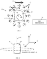
- FIG. 1 illustrates a tissue imaging system 10, constructed and operative in accordance with a non-limiting embodiment of the present invention.
- System 10 includes a stationary array of magnets 12 arranged to create a main magnetic field, which is the static magnetic field (B 0 ).
- the direction of the main magnetic field is indicated by arrow 13.
- magnets 12 are permanent magnets, such as but not limited to, iron or rare earth (e.g., neodymium-iron-boron or samarium-cobalt), or a combination thereof, with or without cores of magnetic material.
- magnets 12 are permanent magnets, whose magnetic field may be shaped with materials such as Mu metals (nickel-iron soft magnetic alloys) cored with other magnetic material (e.g., a soft magnetic material such as iron), which results in an inhomogeneous polarizing field (main magnetic field).
- Mu metals nickel-iron soft magnetic alloys
- other magnetic material e.g., a soft magnetic material such as iron
- the magnets 12 are permanent magnets arranged in accordance with the invention in a Halbach array (e.g., cylindrical array).
- Fig. 3 illustrates an example outside the scope of the invention, in which a pair of magnetic yokes 12A, which may be made of high permeability materials such as Mu metals (nickel-iron soft magnetic alloys) cored with other magnetic material (e.g., a soft magnetic material such as iron), are placed on either side of the tissue 14 and permanent magnets 12B are placed between the yokes 12A.
- Fig. 4 illustrates yet another embodiment, in which magnetic yokes 12A are connected to permanent magnets 12 of the Halbach array.
- the term "yoke” as used herein encompasses any arrangement of magnets with air gaps (such as H-shapes, C-shapes and other shapes, with or without the addition of magnetic material cores.
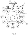
- FIG. 2 illustrates the global coordinate system for imaging.
- the 2D imaging plane is the x-y plane, and each tissue slice is taken along the z axis.
- a tissue sample 14 is disposed in a tissue holder 16, which is rotatable about a rotation axis 18, such as the symmetry axis of holder 16, and/or translatable along any coordinate axis.
- one or more RF receive coils 20 may be mounted adjacent to the tissue 14 and the magnets 12. In the illustrated embodiment, there are more magnets 12 than RF receive coils 20, but in other embodiments there may be the same number of RF receive coils as magnets, or alternatively, there may be more RF receive coils than magnets. In one embodiment, each RF receive coil 20 may be mounted between the tissue 14 and one of the magnets 12. In another embodiment, one or more of the RF receive coils 20 may be mounted between magnets 12.
- the RF receive coils 20 collect a time-varying RF (B 1 ) magnetic field perpendicular to the B 0 field, for example, pointing towards the center of tissue sample 14.
- the RF receive coils 20 may be large enough relative to the sample height so that the intensity of the B 1 field is relatively constant throughout the height of the sample.
- the RF receive coils 20 sense nuclear spins (which may be excited by transmit coils, not shown) in the tissue sample for magnetic resonance as is well known to the skilled artisan.
- the system images a field of view (FOV), as indicated by arrow 15 in Fig. 1 .
- a magnetic resonance imaging processor 30 is in communication with RF receive coils 20 and tissue holder 16.
- the present invention does not need to employ gradient coils to create the MR images. Rather, in this embodiment, the spatial encoding is based on the main magnetic field's inhomogeneity, which is used to polarize, readout, and encode an image of the tissue 14. If the main magnetic field is non-linear, then in order to resolve the non-linear spatial encoding, the imaged tissue 14 is rotated and/or translated within the static main magnetic field and signals are collected from the RF receive coils 20.
- the RF receive coils 20 may either be stationary or may be rotated or displaced within the static magnetic field. This is in contrast to the system of US Patent Application 20140111202 , in which the magnets are rotated and the imaged object is stationary and cannot be rotated.
- the inhomogeneous magnetic field of magnets 12 serves to polarize the tissue 14 to be imaged and to readout magnetic resonance signals.
- Tissue 14 is moved (rotated and/or translated) after each image acquisition, such that tissue 14 has a different spatial orientation for each image acquisition.
- the first acquisition might have the B 0 field oriented transversely from left-to-right through the tissue 14.
- the tissue 14 is then subsequently moved to different spatial orientations, each with a unique magnetic field orientation.
- the spatial inhomogeneities in the magnetic field generated by magnets 12 spatially modulate the magnetic resonance signal phase, such that in conjunction with the rotation and/or translation provides spatial encoding of the signals that can be used to construct an image of the tissue 14.
- the Halbach array configuration of the magnets naturally forms a nonlinear magnetic field whose variation in Larmor frequency (which may vary about 50-100 KHz over the FOV) can be used for spatial encoding, as is known in the art.
- the spatial localization of magnetic resonance signals is improved by using the RF receive coils 20.
- Information from the RF receive coils 20 may be used to reconstruct an image in a process analogous to parallel imaging in conventional MRI.
- the spatially varying coil sensitivities are incorporated directly into the encoding matrix.
- Further image encoding can also be achieved by limiting the bandwidth of the RF excitation pulse used. In this case, the excitation is limited to a constrained "onion-shell" of spatial regions, which may be useful for imaging clean tissue margins.
- shims 22 which may be an iron or Mu metal sheet or a permanent magnet.
- the main magnetic field is generated by the set of permanent magnets 12 shimmed by shim(s) 22 so that a linear field is attained in a way that uses the static magnetic field's permanent, uniform gradient for encoding the spatial location of nuclear spins.
- This uniform gradient can enable using uniform, gradient-dependent MRI contrast parameters, such as ADC (Apparent Diffusion Coefficient), to be imaged.
- the spatial encoding may be based on the main magnetic field's permanent gradient as a readout gradient while the relative rotation between the permanent gradient and the imaged tissue is carried out for a polar phase encoding gradient.
- MR signals are collected from the one or more RF receive coils 20 at different rotation angles of the tissue 14 in a "projection reconstruction" scheme.
- the magnetic field may be homogenous in the z direction so that there are only permanent gradients in the 2D imaging plane alone. This is obtained by using the permanent magnets 12 and shim(s) 22 which are generally constant in the z direction.
- the magnetic field in the x-y plane may have a single vector component in the FOV (or at least with other negligible components) so that imaging may be possible without resorting to complicated processing techniques.
- the goal of shimming is to provide a field which is as linear as possible, i.e., the local gradient is almost constant in magnitude and direction. Realistically it is understood that a certain amount of residual inhomogeneity is present.
- the gradient value takes into consideration the T2 ⁇ -ADC relation so that the resulting value enables a reasonable T2 ⁇ fit for each pixel (a zero gradient disables diffusion expression).
- An accurate local “effective gradient” may be measured so that the T2 ⁇ map attained for each pixel may be transformed to a uniform ADC value which depends only on the tissue microstructure.
- Slice selection may be based upon on the transmit coil's z axis sensitivity. Alternatively, slice selection may be based upon a z direction gradient or other slice encoding schemes.
- FIG. 6 illustrates a method for imaging using PATLOC and resolving ambiguous spatial encoding magnetic fields by relative rotation or displacement, in accordance with an embodiment of the invention.
- PATLOC Parallel Imaging Technique Using Localized Gradients
- SEMs spatial encoding magnetic fields
- a multiple receiver RF coil array is typically used for data acquisition.
- the number of receiver elements in the RF coil array is equal to or greater than the degree of ambiguity present in the SEM.
- a method of resolving the ambiguous spatial encoding includes recording the received signals with a plurality of receiver RF coils and rotating or displacing the imaged object with respect to the encoding field.
- the encoding field and the object are rotated or displaced relative to each other (the object is also moved), and the MR image contrast mechanism is gradient affected (e.g., diffusion weighted MRI).
- the encoding magnetic field employs a plurality of magnets (either permanent or other), possibly in conjunction with gradient coils (outside the scope of the invention) to create an inhomogeneous magnetic field (encoding magnetic field) with a specific relationship between the field and its gradient.
- magnets either permanent or other
- gradient coils outside the scope of the invention
- Spatial encoding may be based on the main magnetic field's inhomogeneity (in accordance with the invention employing a Halbach array) or by using heterogeneous gradient fields (together comprising the SEM).
- an inhomogeneous field is used to polarize, readout, and encode an image of the object.
- the imaged object may be either rotated or displaced within the encoding magnetic field and signals collected from a plurality of RF receiver coils (again as described above for Figs. 1-5 ).
- the received signals from each rotation ⁇ displacement step may be corrected as described below (Local Gradient Correction Method).
- the receive coils may either be stationary or may be rotated or displaced within the encoding magnetic field.
- the gradient's effect on the MR experiment may be normalized by applying a different correction to each frequency component (corresponding to each encoding field's magnitude) according to a predefined gradient calculation (by pure calculation, measurement, calibration, etc.) corresponding to the field's magnitude. This is possible considering the special relationship between the field and its gradient as described above.
- the correction may be performed according to the way the gradient's value affects the image contrast (see the Apparent Diffusion Coefficient Example below) and can be applied in any case the gradient's value can be characterized in the image contrast (such as by contrast weighting by an analytical formula, iterative correction, etc.).
- Data collected from different rotations/displacements of the specimen may be normalized and combined with a gradient-based contrast to reconstruct an image from different acquisitions which took place while the same specimen voxel experienced different local gradients.
- G is the local gradient (which in the general case may be frequency dependent since it may correspond to a certain encoding field magnitude)
- T2 is the spin-spin relaxation time constant
- ⁇ the gyromagnetic ratio
- D the ADC.
- T2 ⁇ is attained by fitting the echoes from a CPMG (Carr-Purcell-Meiboom-Gill) sequence doing this by evaluating each pixel's time decay individually (T2 ⁇ and ADC is calculated for each pixel individually).
- CPMG Carr-Purcell-Meiboom-Gill
- ADC is calculated for each pixel individually.
- a CPMG sequence MR experiment is performed at each step of the rotation.
- Each echo's spectrum is normalized (by a predefined frequency dependent correction function such as an inverse of the above equation considering the relation between the gradient and frequency).
- the PATLOC scheme is then utilized to reconstruct an independent image for each echo.
- Fig. 6 is a graphical illustration of PATLOC acquisition, showing CPMG spin-echo sequences and images constructed therefrom,
- a 'T2 ⁇ like' calculation (of the gradient normalized T2 ⁇ ) may be performed for each pixel (taken from multiple images) finally forming a normalized T2 ⁇ (or ADC weighted) map.
Landscapes
- Physics & Mathematics (AREA)
- General Physics & Mathematics (AREA)
- Condensed Matter Physics & Semiconductors (AREA)
- High Energy & Nuclear Physics (AREA)
- Chemical & Material Sciences (AREA)
- Life Sciences & Earth Sciences (AREA)
- Health & Medical Sciences (AREA)
- Analytical Chemistry (AREA)
- Biochemistry (AREA)
- General Health & Medical Sciences (AREA)
- Immunology (AREA)
- Pathology (AREA)
- Magnetic Resonance Imaging Apparatus (AREA)
Claims (6)
- Un système d'imagerie tissulaire (10) comprenant :un réseau stationnaire d'aimants (12) agencé pour générer un champ magnétique principal non homogène (Bo) ;un support de tissu (16) adjacent audit réseau d'aimants (12) et opérationnel pour déplacer le tissu (14) placé à l'intérieur autour et/ou le long d'un axe de coordonnées ;une ou plusieurs bobines de réception RF (20) adjacentes audit support de tissu (16) et auxdits aimants (12) ; etun processeur IRM (30) en communication avec lesdites bobines de réception RF (20) et ledit support de tissu (16), et agencé pour construire une image du tissu (14) en utilisant un codage spatial des signaux de résonance magnétique générés par lesdits aimants (12) et des bobines de réception RF (20) pour différentes orientations spatiales dudit tissu (14) déplacé par ledit support de tissu (16) par rapport auxdits aimants (12), dans lequel les inhomogénéités spatiales dans le champ magnétique principal modulent spatialement une phase de chacun de les signaux de résonance magnétique, dans lesquels lesdits aimants (12) sont agencés en un réseau de Halbach.
- Le système d'imagerie tissulaire (10) selon la revendication 1, dans lequel lesdites bobines de réception RF (20) sont fixes et ledit support de tissu (16) est agencé à l'intérieur dudit réseau de Halbach.
- Le système d'imagerie tissulaire (10) selon la revendication 1, dans lequel lesdites bobines de réception RF (20) sont mobiles dans ledit champ magnétique principal.
- Le système d'imagerie tissulaire (10) selon la revendication 1, dans lequel lesdits aimants comprennent des culasses magnétiques (12A).
- Le système d'imagerie tissulaire (10) selon la revendication 1, dans lequel lesdits aimants comprennent des culasses magnétiques (12A) connectées à des aimants permanents (12B) dudit réseau de Halbach.
- Le système d'imagerie tissulaire (10) selon la revendication 1, dans lequel lesdits aimants comprennent des aimants permanents (12) et une ou plusieurs cales (22) et ledit support de tissu (16) est disposé à l'intérieur dudit réseau de Halbach.
Applications Claiming Priority (3)
| Application Number | Priority Date | Filing Date | Title |
|---|---|---|---|
| US201662291058P | 2016-02-04 | 2016-02-04 | |
| US201662330942P | 2016-05-03 | 2016-05-03 | |
| PCT/IB2017/050626 WO2017134635A1 (fr) | 2016-02-04 | 2017-02-05 | Système d'imagerie irm utilisant un réseau d'aimants permanents |
Publications (2)
| Publication Number | Publication Date |
|---|---|
| EP3411697A1 EP3411697A1 (fr) | 2018-12-12 |
| EP3411697B1 true EP3411697B1 (fr) | 2021-11-24 |
Family
ID=58358759
Family Applications (1)
| Application Number | Title | Priority Date | Filing Date |
|---|---|---|---|
| EP17711751.2A Active EP3411697B1 (fr) | 2016-02-04 | 2017-02-05 | Système d'imagerie irm utilisant un réseau d'aimants |
Country Status (5)
| Country | Link |
|---|---|
| US (1) | US10746827B2 (fr) |
| EP (1) | EP3411697B1 (fr) |
| JP (1) | JP2019512083A (fr) |
| CN (1) | CN109196341A (fr) |
| WO (1) | WO2017134635A1 (fr) |
Cited By (1)
| Publication number | Priority date | Publication date | Assignee | Title |
|---|---|---|---|---|
| US20210407717A1 (en) * | 2018-11-05 | 2021-12-30 | Bionaut Labs Ltd. | Magnetic propulsion system for magnetic devices |
Families Citing this family (9)
| Publication number | Priority date | Publication date | Assignee | Title |
|---|---|---|---|---|
| WO2018175807A1 (fr) * | 2017-03-22 | 2018-09-27 | Viewray Technologies, Inc. | Réduction d'artefacts dans une imagerie par résonance magnétique par création d'inhomogénéité dans le champ magnétique à une position de gradient zéro d'un système irm |
| US10585154B1 (en) * | 2018-01-29 | 2020-03-10 | Quantum Valley Investment Fund LP | Nuclear magnetic resonance diffraction |
| WO2020109894A1 (fr) | 2018-11-29 | 2020-06-04 | Epsitau Ltd. | Réseaux d'aimants asymétriques légers |
| CA3121601A1 (fr) | 2018-11-29 | 2020-06-04 | Epsitau Ltd. | Reseaux d'aimants asymetriques legers avec anneaux magnetiques a phase mixte |
| JP7369470B2 (ja) | 2018-11-29 | 2023-10-26 | エプシタウ リミテッド | 混合相磁石リングを備える軽量の非対称磁石アレイ |
| US11275137B2 (en) * | 2019-12-10 | 2022-03-15 | Hyperfine, Inc. | Permanent magnet assembly for magnetic resonance imaging with non-ferromagnetic frame |
| CN115552270A (zh) | 2019-12-10 | 2022-12-30 | 海珀菲纳运营有限公司 | 用于磁共振成像的铁磁框架 |
| US20240012074A1 (en) * | 2020-11-04 | 2024-01-11 | Clear-Cut Medical Ltd. | Improved rf coil for inside-out nmr/mri systems |
| CN116449274A (zh) * | 2023-04-17 | 2023-07-18 | 重庆邮电大学 | 基于磁体旋转和射频相位编码的便携式磁共振成像系统 |
Family Cites Families (26)
| Publication number | Priority date | Publication date | Assignee | Title |
|---|---|---|---|---|
| US4305036A (en) * | 1979-07-09 | 1981-12-08 | Gesellschaft Fur Biotechnologische Forschung Mbh | Method and apparatus for high resolution nuclear magnetic resonance spectroscopy |
| US4301410A (en) * | 1979-09-28 | 1981-11-17 | International Business Machines Corporation | Spin imaging in solids using synchronously rotating field gradients and samples |
| USH1218H (en) * | 1992-05-06 | 1993-08-03 | NMR imaging with varying spatial coupling | |
| DE4442742C1 (de) * | 1994-12-01 | 1996-05-23 | Bruker Analytische Messtechnik | Probenkopf für die Kernresonanz-Spektroskopie |
| JP2004159984A (ja) * | 2002-11-14 | 2004-06-10 | Ge Medical Systems Global Technology Co Llc | 静磁場形成装置および磁気共鳴撮像装置 |
| AU2004203173A1 (en) * | 2003-07-14 | 2005-02-03 | Sunnybrook And Women's College And Health Sciences Centre | Optical image-based position tracking for magnetic resonance imaging |
| GB2425842A (en) * | 2005-05-05 | 2006-11-08 | Plant Bioscience Ltd | Magnetic resonance sensor with rotatable magnetic rods placed around the sample |
| US8604787B2 (en) * | 2006-04-27 | 2013-12-10 | Stefan Posse | Magnetic resonance spectroscopy with real-time correction of motion and frequency drift, and real-time shimming |
| GB2445759A (en) | 2006-11-28 | 2008-07-23 | Inst Of Food Res | Magnetic resonance imaging scanner |
| US7683615B2 (en) * | 2006-12-20 | 2010-03-23 | Schlumberger Technology Corporation | Method and apparatus to improve NMR spectral resolution in an inhomogeneous magnetic field |
| US8198607B2 (en) * | 2008-05-22 | 2012-06-12 | Vladimir Balakin | Tandem accelerator method and apparatus used in conjunction with a charged particle cancer therapy system |
| EP4270143A3 (fr) * | 2008-06-23 | 2023-12-27 | The Regents Of The University Of California, Berkeley | Techniques améliorées pour l imagerie de particules magnétiques |
| CN101430371B (zh) * | 2008-12-19 | 2012-07-18 | 中国科学院电工研究所 | 一种磁共振成像的方法及其装置 |
| EP2565663B1 (fr) * | 2010-02-01 | 2016-12-14 | Clear-Cut Medical Ltd | Évaluation de marge d'une tumeur dans un échantillon ex-vivo |
| DE102011083898B4 (de) * | 2011-09-30 | 2013-04-11 | Friedrich-Alexander-Universität Erlangen-Nürnberg | Erfassen von Magnetresonanzdaten am Rande des Gesichtsfelds einer Magnetresonanzanlage |
| CN104303067B (zh) * | 2012-03-21 | 2017-05-03 | 明确医疗有限公司 | 用于离体样本的边缘估计的mri系统 |
| US10359481B2 (en) * | 2012-06-15 | 2019-07-23 | The General Hospital Corporation | System and method for portable magnetic resonance imaging using a rotating array of permanent magnets |
| US9910115B2 (en) | 2012-10-22 | 2018-03-06 | The General Hospital Corporation | System and method for portable magnetic resonance imaging using a rotating array of magnets |
| US9720128B2 (en) * | 2013-02-15 | 2017-08-01 | Schlumberger Technology Corporation | Rotating frame pulsed nuclear magnetic resonance spectroscopy |
| BR112015030364B1 (pt) * | 2013-06-03 | 2022-02-08 | Nanalysis Corp | Conjunto de imãs |
| US9651687B2 (en) * | 2014-10-22 | 2017-05-16 | Siemens Medical Solutions Usa, Inc. | Positron attenuation tomography |
| US10194829B2 (en) * | 2015-07-07 | 2019-02-05 | Q Bio, Inc. | Fast scanning based on magnetic resonance history |
| US9958521B2 (en) * | 2015-07-07 | 2018-05-01 | Q Bio, Inc. | Field-invariant quantitative magnetic-resonance signatures |
| US10222441B2 (en) * | 2016-04-03 | 2019-03-05 | Q Bio, Inc. | Tensor field mapping |
| DE102016113138B4 (de) * | 2016-07-15 | 2018-02-15 | Fraunhofer-Gesellschaft zur Förderung der angewandten Forschung e.V. | System, insbesondere Magnetresonanzsystem, zum Erzeugen von Bildern |
| EP3557276B1 (fr) * | 2018-04-16 | 2024-07-03 | Siemens Healthineers AG | Procédé et système d'imagerie par résonance magnétique destinés à la génération d'images par résonance magnétique à l'interieur et à l'exterieur du volume d'homogénéité du champ magnétique b0 |
-
2017
- 2017-02-05 EP EP17711751.2A patent/EP3411697B1/fr active Active
- 2017-02-05 CN CN201780009463.6A patent/CN109196341A/zh active Pending
- 2017-02-05 JP JP2018540769A patent/JP2019512083A/ja active Pending
- 2017-02-05 WO PCT/IB2017/050626 patent/WO2017134635A1/fr not_active Ceased
- 2017-02-05 US US16/074,497 patent/US10746827B2/en active Active
Cited By (2)
| Publication number | Priority date | Publication date | Assignee | Title |
|---|---|---|---|---|
| US20210407717A1 (en) * | 2018-11-05 | 2021-12-30 | Bionaut Labs Ltd. | Magnetic propulsion system for magnetic devices |
| US12040131B2 (en) * | 2018-11-05 | 2024-07-16 | Bionaut Labs Ltd. | Magnetic propulsion system for magnetic devices |
Also Published As
| Publication number | Publication date |
|---|---|
| US10746827B2 (en) | 2020-08-18 |
| WO2017134635A1 (fr) | 2017-08-10 |
| CN109196341A (zh) | 2019-01-11 |
| JP2019512083A (ja) | 2019-05-09 |
| EP3411697A1 (fr) | 2018-12-12 |
| US20190041477A1 (en) | 2019-02-07 |
Similar Documents
| Publication | Publication Date | Title |
|---|---|---|
| EP3411697B1 (fr) | Système d'imagerie irm utilisant un réseau d'aimants | |
| Baldwin et al. | A two‐step scheme for distortion rectification of magnetic resonance images | |
| US6445182B1 (en) | Geometric distortion correction in magnetic resonance imaging | |
| US8558547B2 (en) | System and method for magnetic resonance radio-frequency field mapping | |
| US9766313B2 (en) | MR imaging using apt contrast enhancement and sampling at multiple echo times | |
| US9977108B2 (en) | Metal resistant MR imaging reference scan | |
| EP2615470A1 (fr) | Imagerie par RM avec cartographie B1 | |
| US11047935B2 (en) | Systems and methods for estimating complex B1+ fields of transmit coils of a magnetic resonance imaging (MRI) system | |
| JP6458170B2 (ja) | Rfコイル感度マッピングを用いるパラレルmr撮像 | |
| US20090253983A1 (en) | Image based measurement of contrast agents | |
| EP1366373A2 (fr) | Procede d'analyse par resonance magnetique a haute resolution utilisant la technique de l'angle magique | |
| EP2979106A1 (fr) | Imagerie par transfert de proton d'amide (apt) et tomographie de propriétés électriques (ept) en une seule acquisition rm | |
| US20100016708A1 (en) | Mri rf encoding using multiple transmit coils | |
| WO2014059237A1 (fr) | Systèmes et procédés pour imagerie de tenseur de susceptibilité dans l'espace p | |
| KR20140035838A (ko) | 자기 공명 시스템을 제어하는 방법 및 제어 장치 | |
| US20120153950A1 (en) | Rf shimmed mri slice excitation along a curved spoke k-space trajectory | |
| US20150153431A1 (en) | Systems and methods for determining electrical properties using magnetic resonance imaging | |
| EP3828580B1 (fr) | Procédé et système de compensation de champs magnétiques parasites dans un système d'imagerie par résonance magnétique avec plusieurs zones d'examen | |
| US20240382103A1 (en) | Magnetic resonance tomography unit for localizing metallic objects and operating method | |
| JP2026501800A (ja) | 片面式MRIのための交差項時空間エンコーディング(xSPEN)技術 | |
| CN107907842B (zh) | 一种极弱磁性材料的检测方法 | |
| Schwerter et al. | Advanced software and hardware control methods for improved static and dynamic B0 shimming in magnetic resonance imaging | |
| US20220143425A1 (en) | Method and apparatus for taking into account susceptibility deviations in mr-based therapy planning | |
| McNabb et al. | Localizing implanted fiducial markers using undersampled co-RASOR MR imaging | |
| Bergen | Optimizing and advancing multiparametric magnetic resonance imaging for biologically-guided radiotherapy |
Legal Events
| Date | Code | Title | Description |
|---|---|---|---|
| STAA | Information on the status of an ep patent application or granted ep patent |
Free format text: STATUS: UNKNOWN |
|
| STAA | Information on the status of an ep patent application or granted ep patent |
Free format text: STATUS: THE INTERNATIONAL PUBLICATION HAS BEEN MADE |
|
| PUAI | Public reference made under article 153(3) epc to a published international application that has entered the european phase |
Free format text: ORIGINAL CODE: 0009012 |
|
| STAA | Information on the status of an ep patent application or granted ep patent |
Free format text: STATUS: REQUEST FOR EXAMINATION WAS MADE |
|
| 17P | Request for examination filed |
Effective date: 20180803 |
|
| AK | Designated contracting states |
Kind code of ref document: A1 Designated state(s): AL AT BE BG CH CY CZ DE DK EE ES FI FR GB GR HR HU IE IS IT LI LT LU LV MC MK MT NL NO PL PT RO RS SE SI SK SM TR |
|
| AX | Request for extension of the european patent |
Extension state: BA ME |
|
| DAV | Request for validation of the european patent (deleted) | ||
| DAX | Request for extension of the european patent (deleted) | ||
| STAA | Information on the status of an ep patent application or granted ep patent |
Free format text: STATUS: EXAMINATION IS IN PROGRESS |
|
| 17Q | First examination report despatched |
Effective date: 20210205 |
|
| GRAP | Despatch of communication of intention to grant a patent |
Free format text: ORIGINAL CODE: EPIDOSNIGR1 |
|
| STAA | Information on the status of an ep patent application or granted ep patent |
Free format text: STATUS: GRANT OF PATENT IS INTENDED |
|
| INTG | Intention to grant announced |
Effective date: 20210901 |
|
| RAP3 | Party data changed (applicant data changed or rights of an application transferred) |
Owner name: CLEAR-CUT MEDICAL LTD. |
|
| GRAS | Grant fee paid |
Free format text: ORIGINAL CODE: EPIDOSNIGR3 |
|
| GRAA | (expected) grant |
Free format text: ORIGINAL CODE: 0009210 |
|
| STAA | Information on the status of an ep patent application or granted ep patent |
Free format text: STATUS: THE PATENT HAS BEEN GRANTED |
|
| AK | Designated contracting states |
Kind code of ref document: B1 Designated state(s): AL AT BE BG CH CY CZ DE DK EE ES FI FR GB GR HR HU IE IS IT LI LT LU LV MC MK MT NL NO PL PT RO RS SE SI SK SM TR |
|
| REG | Reference to a national code |
Ref country code: GB Ref legal event code: FG4D |
|
| REG | Reference to a national code |
Ref country code: DE Ref legal event code: R096 Ref document number: 602017049744 Country of ref document: DE |
|
| REG | Reference to a national code |
Ref country code: AT Ref legal event code: REF Ref document number: 1450227 Country of ref document: AT Kind code of ref document: T Effective date: 20211215 |
|
| REG | Reference to a national code |
Ref country code: IE Ref legal event code: FG4D |
|
| REG | Reference to a national code |
Ref country code: LT Ref legal event code: MG9D |
|
| REG | Reference to a national code |
Ref country code: NL Ref legal event code: MP Effective date: 20211124 |
|
| REG | Reference to a national code |
Ref country code: AT Ref legal event code: MK05 Ref document number: 1450227 Country of ref document: AT Kind code of ref document: T Effective date: 20211124 |
|
| PG25 | Lapsed in a contracting state [announced via postgrant information from national office to epo] |
Ref country code: RS Free format text: LAPSE BECAUSE OF FAILURE TO SUBMIT A TRANSLATION OF THE DESCRIPTION OR TO PAY THE FEE WITHIN THE PRESCRIBED TIME-LIMIT Effective date: 20211124 Ref country code: LT Free format text: LAPSE BECAUSE OF FAILURE TO SUBMIT A TRANSLATION OF THE DESCRIPTION OR TO PAY THE FEE WITHIN THE PRESCRIBED TIME-LIMIT Effective date: 20211124 Ref country code: FI Free format text: LAPSE BECAUSE OF FAILURE TO SUBMIT A TRANSLATION OF THE DESCRIPTION OR TO PAY THE FEE WITHIN THE PRESCRIBED TIME-LIMIT Effective date: 20211124 Ref country code: BG Free format text: LAPSE BECAUSE OF FAILURE TO SUBMIT A TRANSLATION OF THE DESCRIPTION OR TO PAY THE FEE WITHIN THE PRESCRIBED TIME-LIMIT Effective date: 20220224 Ref country code: AT Free format text: LAPSE BECAUSE OF FAILURE TO SUBMIT A TRANSLATION OF THE DESCRIPTION OR TO PAY THE FEE WITHIN THE PRESCRIBED TIME-LIMIT Effective date: 20211124 |
|
| PG25 | Lapsed in a contracting state [announced via postgrant information from national office to epo] |
Ref country code: IS Free format text: LAPSE BECAUSE OF FAILURE TO SUBMIT A TRANSLATION OF THE DESCRIPTION OR TO PAY THE FEE WITHIN THE PRESCRIBED TIME-LIMIT Effective date: 20220324 Ref country code: SE Free format text: LAPSE BECAUSE OF FAILURE TO SUBMIT A TRANSLATION OF THE DESCRIPTION OR TO PAY THE FEE WITHIN THE PRESCRIBED TIME-LIMIT Effective date: 20211124 Ref country code: PT Free format text: LAPSE BECAUSE OF FAILURE TO SUBMIT A TRANSLATION OF THE DESCRIPTION OR TO PAY THE FEE WITHIN THE PRESCRIBED TIME-LIMIT Effective date: 20220324 Ref country code: PL Free format text: LAPSE BECAUSE OF FAILURE TO SUBMIT A TRANSLATION OF THE DESCRIPTION OR TO PAY THE FEE WITHIN THE PRESCRIBED TIME-LIMIT Effective date: 20211124 Ref country code: NO Free format text: LAPSE BECAUSE OF FAILURE TO SUBMIT A TRANSLATION OF THE DESCRIPTION OR TO PAY THE FEE WITHIN THE PRESCRIBED TIME-LIMIT Effective date: 20220224 Ref country code: NL Free format text: LAPSE BECAUSE OF FAILURE TO SUBMIT A TRANSLATION OF THE DESCRIPTION OR TO PAY THE FEE WITHIN THE PRESCRIBED TIME-LIMIT Effective date: 20211124 Ref country code: LV Free format text: LAPSE BECAUSE OF FAILURE TO SUBMIT A TRANSLATION OF THE DESCRIPTION OR TO PAY THE FEE WITHIN THE PRESCRIBED TIME-LIMIT Effective date: 20211124 Ref country code: HR Free format text: LAPSE BECAUSE OF FAILURE TO SUBMIT A TRANSLATION OF THE DESCRIPTION OR TO PAY THE FEE WITHIN THE PRESCRIBED TIME-LIMIT Effective date: 20211124 Ref country code: GR Free format text: LAPSE BECAUSE OF FAILURE TO SUBMIT A TRANSLATION OF THE DESCRIPTION OR TO PAY THE FEE WITHIN THE PRESCRIBED TIME-LIMIT Effective date: 20220225 Ref country code: ES Free format text: LAPSE BECAUSE OF FAILURE TO SUBMIT A TRANSLATION OF THE DESCRIPTION OR TO PAY THE FEE WITHIN THE PRESCRIBED TIME-LIMIT Effective date: 20211124 |
|
| PG25 | Lapsed in a contracting state [announced via postgrant information from national office to epo] |
Ref country code: SM Free format text: LAPSE BECAUSE OF FAILURE TO SUBMIT A TRANSLATION OF THE DESCRIPTION OR TO PAY THE FEE WITHIN THE PRESCRIBED TIME-LIMIT Effective date: 20211124 Ref country code: SK Free format text: LAPSE BECAUSE OF FAILURE TO SUBMIT A TRANSLATION OF THE DESCRIPTION OR TO PAY THE FEE WITHIN THE PRESCRIBED TIME-LIMIT Effective date: 20211124 Ref country code: RO Free format text: LAPSE BECAUSE OF FAILURE TO SUBMIT A TRANSLATION OF THE DESCRIPTION OR TO PAY THE FEE WITHIN THE PRESCRIBED TIME-LIMIT Effective date: 20211124 Ref country code: EE Free format text: LAPSE BECAUSE OF FAILURE TO SUBMIT A TRANSLATION OF THE DESCRIPTION OR TO PAY THE FEE WITHIN THE PRESCRIBED TIME-LIMIT Effective date: 20211124 Ref country code: DK Free format text: LAPSE BECAUSE OF FAILURE TO SUBMIT A TRANSLATION OF THE DESCRIPTION OR TO PAY THE FEE WITHIN THE PRESCRIBED TIME-LIMIT Effective date: 20211124 Ref country code: CZ Free format text: LAPSE BECAUSE OF FAILURE TO SUBMIT A TRANSLATION OF THE DESCRIPTION OR TO PAY THE FEE WITHIN THE PRESCRIBED TIME-LIMIT Effective date: 20211124 |
|
| REG | Reference to a national code |
Ref country code: DE Ref legal event code: R097 Ref document number: 602017049744 Country of ref document: DE |
|
| PG25 | Lapsed in a contracting state [announced via postgrant information from national office to epo] |
Ref country code: MC Free format text: LAPSE BECAUSE OF FAILURE TO SUBMIT A TRANSLATION OF THE DESCRIPTION OR TO PAY THE FEE WITHIN THE PRESCRIBED TIME-LIMIT Effective date: 20211124 |
|
| PLBE | No opposition filed within time limit |
Free format text: ORIGINAL CODE: 0009261 |
|
| STAA | Information on the status of an ep patent application or granted ep patent |
Free format text: STATUS: NO OPPOSITION FILED WITHIN TIME LIMIT |
|
| REG | Reference to a national code |
Ref country code: CH Ref legal event code: PL |
|
| REG | Reference to a national code |
Ref country code: BE Ref legal event code: MM Effective date: 20220228 |
|
| PG25 | Lapsed in a contracting state [announced via postgrant information from national office to epo] |
Ref country code: LU Free format text: LAPSE BECAUSE OF NON-PAYMENT OF DUE FEES Effective date: 20220205 Ref country code: AL Free format text: LAPSE BECAUSE OF FAILURE TO SUBMIT A TRANSLATION OF THE DESCRIPTION OR TO PAY THE FEE WITHIN THE PRESCRIBED TIME-LIMIT Effective date: 20211124 |
|
| 26N | No opposition filed |
Effective date: 20220825 |
|
| PG25 | Lapsed in a contracting state [announced via postgrant information from national office to epo] |
Ref country code: SI Free format text: LAPSE BECAUSE OF FAILURE TO SUBMIT A TRANSLATION OF THE DESCRIPTION OR TO PAY THE FEE WITHIN THE PRESCRIBED TIME-LIMIT Effective date: 20211124 |
|
| PG25 | Lapsed in a contracting state [announced via postgrant information from national office to epo] |
Ref country code: LI Free format text: LAPSE BECAUSE OF NON-PAYMENT OF DUE FEES Effective date: 20220228 Ref country code: CH Free format text: LAPSE BECAUSE OF NON-PAYMENT OF DUE FEES Effective date: 20220228 |
|
| PG25 | Lapsed in a contracting state [announced via postgrant information from national office to epo] |
Ref country code: BE Free format text: LAPSE BECAUSE OF NON-PAYMENT OF DUE FEES Effective date: 20220228 |
|
| PG25 | Lapsed in a contracting state [announced via postgrant information from national office to epo] |
Ref country code: HU Free format text: LAPSE BECAUSE OF FAILURE TO SUBMIT A TRANSLATION OF THE DESCRIPTION OR TO PAY THE FEE WITHIN THE PRESCRIBED TIME-LIMIT; INVALID AB INITIO Effective date: 20170205 |
|
| PG25 | Lapsed in a contracting state [announced via postgrant information from national office to epo] |
Ref country code: MK Free format text: LAPSE BECAUSE OF FAILURE TO SUBMIT A TRANSLATION OF THE DESCRIPTION OR TO PAY THE FEE WITHIN THE PRESCRIBED TIME-LIMIT Effective date: 20211124 Ref country code: CY Free format text: LAPSE BECAUSE OF FAILURE TO SUBMIT A TRANSLATION OF THE DESCRIPTION OR TO PAY THE FEE WITHIN THE PRESCRIBED TIME-LIMIT Effective date: 20211124 |
|
| PG25 | Lapsed in a contracting state [announced via postgrant information from national office to epo] |
Ref country code: TR Free format text: LAPSE BECAUSE OF FAILURE TO SUBMIT A TRANSLATION OF THE DESCRIPTION OR TO PAY THE FEE WITHIN THE PRESCRIBED TIME-LIMIT Effective date: 20211124 |
|
| PG25 | Lapsed in a contracting state [announced via postgrant information from national office to epo] |
Ref country code: MT Free format text: LAPSE BECAUSE OF FAILURE TO SUBMIT A TRANSLATION OF THE DESCRIPTION OR TO PAY THE FEE WITHIN THE PRESCRIBED TIME-LIMIT Effective date: 20211124 |
|
| PGFP | Annual fee paid to national office [announced via postgrant information from national office to epo] |
Ref country code: GB Payment date: 20260219 Year of fee payment: 10 |
|
| PGFP | Annual fee paid to national office [announced via postgrant information from national office to epo] |
Ref country code: DE Payment date: 20260108 Year of fee payment: 10 Ref country code: IE Payment date: 20260218 Year of fee payment: 10 |
|
| PGFP | Annual fee paid to national office [announced via postgrant information from national office to epo] |
Ref country code: IT Payment date: 20260227 Year of fee payment: 10 |
|
| PGFP | Annual fee paid to national office [announced via postgrant information from national office to epo] |
Ref country code: FR Payment date: 20260223 Year of fee payment: 10 |