EP3412131A1 - Système de traitement de sol comprenant une adaptation de signal - Google Patents
Système de traitement de sol comprenant une adaptation de signal Download PDFInfo
- Publication number
- EP3412131A1 EP3412131A1 EP17400031.5A EP17400031A EP3412131A1 EP 3412131 A1 EP3412131 A1 EP 3412131A1 EP 17400031 A EP17400031 A EP 17400031A EP 3412131 A1 EP3412131 A1 EP 3412131A1
- Authority
- EP
- European Patent Office
- Prior art keywords
- wire
- signal
- soil cultivation
- cultivation system
- transmitted
- Prior art date
- Legal status (The legal status is an assumption and is not a legal conclusion. Google has not performed a legal analysis and makes no representation as to the accuracy of the status listed.)
- Granted
Links
Images
Classifications
-
- H—ELECTRICITY
- H04—ELECTRIC COMMUNICATION TECHNIQUE
- H04B—TRANSMISSION
- H04B5/00—Near-field transmission systems, e.g. inductive or capacitive transmission systems
- H04B5/70—Near-field transmission systems, e.g. inductive or capacitive transmission systems specially adapted for specific purposes
- H04B5/72—Near-field transmission systems, e.g. inductive or capacitive transmission systems specially adapted for specific purposes for local intradevice communication
-
- A—HUMAN NECESSITIES
- A01—AGRICULTURE; FORESTRY; ANIMAL HUSBANDRY; HUNTING; TRAPPING; FISHING
- A01D—HARVESTING; MOWING
- A01D34/00—Mowers; Mowing apparatus of harvesters
- A01D34/006—Control or measuring arrangements
- A01D34/008—Control or measuring arrangements for automated or remotely controlled operation
-
- A—HUMAN NECESSITIES
- A01—AGRICULTURE; FORESTRY; ANIMAL HUSBANDRY; HUNTING; TRAPPING; FISHING
- A01D—HARVESTING; MOWING
- A01D69/00—Driving mechanisms or parts thereof for harvesters or mowers
- A01D69/007—Driving mechanisms or parts thereof for harvesters or mowers with separate hand drive for cutting tools
-
- G—PHYSICS
- G05—CONTROLLING; REGULATING
- G05D—SYSTEMS FOR CONTROLLING OR REGULATING NON-ELECTRIC VARIABLES
- G05D1/00—Control of position, course, altitude or attitude of land, water, air or space vehicles, e.g. using automatic pilots
- G05D1/0011—Control of position, course, altitude or attitude of land, water, air or space vehicles, e.g. using automatic pilots associated with a remote control arrangement
- G05D1/0016—Control of position, course, altitude or attitude of land, water, air or space vehicles, e.g. using automatic pilots associated with a remote control arrangement characterised by the operator's input device
-
- G—PHYSICS
- G05—CONTROLLING; REGULATING
- G05D—SYSTEMS FOR CONTROLLING OR REGULATING NON-ELECTRIC VARIABLES
- G05D1/00—Control of position, course, altitude or attitude of land, water, air or space vehicles, e.g. using automatic pilots
- G05D1/0011—Control of position, course, altitude or attitude of land, water, air or space vehicles, e.g. using automatic pilots associated with a remote control arrangement
- G05D1/0022—Control of position, course, altitude or attitude of land, water, air or space vehicles, e.g. using automatic pilots associated with a remote control arrangement characterised by the communication link
-
- G—PHYSICS
- G05—CONTROLLING; REGULATING
- G05D—SYSTEMS FOR CONTROLLING OR REGULATING NON-ELECTRIC VARIABLES
- G05D1/00—Control of position, course, altitude or attitude of land, water, air or space vehicles, e.g. using automatic pilots
- G05D1/02—Control of position or course in two dimensions
- G05D1/021—Control of position or course in two dimensions specially adapted to land vehicles
- G05D1/0259—Control of position or course in two dimensions specially adapted to land vehicles using magnetic or electromagnetic means
- G05D1/0265—Control of position or course in two dimensions specially adapted to land vehicles using magnetic or electromagnetic means using buried wires
-
- H—ELECTRICITY
- H04—ELECTRIC COMMUNICATION TECHNIQUE
- H04B—TRANSMISSION
- H04B5/00—Near-field transmission systems, e.g. inductive or capacitive transmission systems
- H04B5/20—Near-field transmission systems, e.g. inductive or capacitive transmission systems characterised by the transmission technique; characterised by the transmission medium
- H04B5/24—Inductive coupling
-
- H—ELECTRICITY
- H04—ELECTRIC COMMUNICATION TECHNIQUE
- H04B—TRANSMISSION
- H04B5/00—Near-field transmission systems, e.g. inductive or capacitive transmission systems
- H04B5/20—Near-field transmission systems, e.g. inductive or capacitive transmission systems characterised by the transmission technique; characterised by the transmission medium
- H04B5/28—Near-field transmission systems, e.g. inductive or capacitive transmission systems characterised by the transmission technique; characterised by the transmission medium using the near field of leaky cables, e.g. of leaky coaxial cables
-
- A—HUMAN NECESSITIES
- A01—AGRICULTURE; FORESTRY; ANIMAL HUSBANDRY; HUNTING; TRAPPING; FISHING
- A01B—SOIL WORKING IN AGRICULTURE OR FORESTRY; PARTS, DETAILS, OR ACCESSORIES OF AGRICULTURAL MACHINES OR IMPLEMENTS, IN GENERAL
- A01B69/00—Steering of agricultural machines or implements; Guiding agricultural machines or implements on a desired track
- A01B69/007—Steering or guiding of agricultural vehicles, e.g. steering of the tractor to keep the plough in the furrow
- A01B69/008—Steering or guiding of agricultural vehicles, e.g. steering of the tractor to keep the plough in the furrow automatic
-
- A—HUMAN NECESSITIES
- A01—AGRICULTURE; FORESTRY; ANIMAL HUSBANDRY; HUNTING; TRAPPING; FISHING
- A01D—HARVESTING; MOWING
- A01D2101/00—Lawn-mowers
-
- A—HUMAN NECESSITIES
- A01—AGRICULTURE; FORESTRY; ANIMAL HUSBANDRY; HUNTING; TRAPPING; FISHING
- A01D—HARVESTING; MOWING
- A01D34/00—Mowers; Mowing apparatus of harvesters
- A01D34/01—Mowers; Mowing apparatus of harvesters characterised by features relating to the type of cutting apparatus
- A01D34/412—Mowers; Mowing apparatus of harvesters characterised by features relating to the type of cutting apparatus having rotating cutters
- A01D34/63—Mowers; Mowing apparatus of harvesters characterised by features relating to the type of cutting apparatus having rotating cutters having cutters rotating about a vertical axis
- A01D34/64—Mowers; Mowing apparatus of harvesters characterised by features relating to the type of cutting apparatus having rotating cutters having cutters rotating about a vertical axis mounted on a vehicle, e.g. a tractor, or drawn by an animal or a vehicle
-
- A—HUMAN NECESSITIES
- A01—AGRICULTURE; FORESTRY; ANIMAL HUSBANDRY; HUNTING; TRAPPING; FISHING
- A01D—HARVESTING; MOWING
- A01D69/00—Driving mechanisms or parts thereof for harvesters or mowers
- A01D69/02—Driving mechanisms or parts thereof for harvesters or mowers electric
Definitions
- the invention relates to a soil cultivation system comprising at least one self-propelled soil cultivation device, which has a drive and a control unit.
- a work area delimited by a deckle wire is provided, with the ground working implement leaving a travel path determined by the control unit in the work area.
- a base station with a transmitting unit connected to the electrical deckle wire, via which a wire signal is transmitted on the deckle wire.
- the electromagnetic field of the wire signal will induce a receive signal in a receiver coil of the tillage implement, which is processed in the control unit for determining the driveway and the driving behavior.
- Every wire that is physically installed as a perimeter boundary initially has ohmic properties and also inductive or capacitive properties depending on the installed shape and the laid tramlines. Therefore, a wire signal applied to the wire is attenuated over the entire length of the wire. The wire signal changes in amplitude and waveform due to the geometric and electrical properties of the wire. Therefore, proper control of the tillage implements may be compromised especially at a greater distance from the wire.
- the transmitted wire signals must not be arbitrarily strong, since their electromagnetic field other, for. B. adjacent tillage systems would affect their function.
- the wire signal is designed to be too weak electrically, interference signals occurring in the vicinity of the soil cultivation device can impair the functional safety of the operation of the soil cultivation devices.
- the invention has for its object to form a tillage system with a wire as the boundary of a work area such that on the one hand over the entire length of the wire of a deckle for the correct functioning of the tillage sufficiently strong wire signal is applied and on the other hand, an electromagnetic impairment of the environment is minimized.
- the wire signal transmitted on the wire of the deckle is electrically received, in particular parallel to the transmitting unit, by a receiving unit of the base station.
- This received wire signal is compared with a predetermined target signal to be at a deviation of the received wire signal from the predetermined Target signal to change the transmitted wire signal.
- the received wire signal is changed in such a way that it approximates the predetermined reference signal or corresponds to it in particular.
- the receiving unit electrically picks up the transmitted wire signal at the same time as the wire is transmitted, so that the transmitted wire signal is measured at the same time in the receiving unit.
- Receiving unit and transmitting unit are provided in the same base station and operate regardless of the length of the wire and the laid geometric shape of the wire. The user does not need to enter any entries for the laid edge limitation, the length of the laid wire or the distance from parallel wire sections. Also, on sensors z. B. are omitted for detecting the electromagnetic field. The base station automatically optimally adjusts the transmitted wire signal without intervention by the user.
- the attenuation of the wire signal in particular the ohmic, inductive and / or capacitive influencing factors of the laid as a boundary boundary wire can be compensated to a large extent.
- the signal to be transmitted wire signal in its amplitude, its waveform and / or in its time course can be adjusted via the signal conditioning device.
- the predetermined reference signal does not necessarily correspond to the transmitted wire signal. Rather, the transmitted wire signal and the predetermined desired signal may differ in amplitude and / or signal shape. It may also be expedient to provide the signal conditioning device with a selection of permissible nominal signals. Depending on the deviations of the received wire signal from a predefined setpoint signal, the signal conditioning device can decide which signal form, signal strength and signal time are advantageous for the connected wire loop. Thus, without any user having to intervene, any wire routed on site in any form will serve as a boundary be operated with an optimal wire signal, which ensures a fail-safe control of tillage equipment throughout the work area.
- the wire of the edge boundary is laid as a wire loop, wherein the wire loop is electrically connected at its terminal ends with a transmitting unit.
- the receiving unit is connected electrically parallel to the transmitting unit to the wire of the deckle.
- the terminal ends of the wire loop are electrically connected to the receiving unit.
- the transmitting unit and the receiving unit communicate in a further development of the invention via a signal processing device with each other.
- the transmitting unit, the wire of the boundary, the receiving unit and the signal processing device form a control loop.
- the signal conditioner determines whether the wire signal to be transmitted is to be changed, e.g., depending on the detected deviations between the received wire signal and the predetermined target signal. is to be amplified in its amplitude, to change in its waveform or in its time course such. B. is to be adapted in frequency.
- the base station is also designed as a charging station for a battery of the harrow.
- the tillage device moves in accordance with low state of charge of the onboard battery in the base station as a charging station.
- the soil cultivation device is a self-propelled lawn mower.
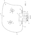
- This in Fig. 1 illustrated tillage system S comprises at least one self-propelled tillage implement 1.1, 1.2 for processing a predetermined work area A.
- two tillage machines 1.1 and 1.2 are provided for the common processing of the work area A.
- the tillage system S may include fewer or more tillage implements.
- Each individual tillage device 1.1, 1.2 operates autonomously and autonomously travels within the work area A a random, predetermined or independently planned route W from.
- the working area A of the tillage system S is limited by a wire 43.
- the wire 43 forms a boundary of the working area A and is laid in particular as a closed wire loop 2.
- the terminal ends 3 and 4 of the wire loop 2 are connected to a transmitting / receiving unit 5 of a base station 8.
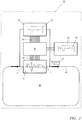
- terminal ends 3 and 4 of the wire 43 are connected to a transmitting unit 32.
- Via the transmitting unit 32 - preferably at fixed intervals - electrical wire signals 41 are transmitted on the wire 43 of the deckle.
- the terminal ends 3 and 4 of the wire 43 of the wire loop 2 are connected to a receiving unit 31 which electrically receives the wire signal 41 sent to the wire 43 of the deckle.
- the receiving unit 31 and the transmitting unit 32 are connected to one another via a signal conditioning device 30.
- the receiving unit 31, the signal processing device 30 and the transmitting unit 32 together with the wire of the closed wire loop 2 form a control circuit 38 (FIG. Fig. 3 ).
- the function of the control circuit 38 will be described in detail below.
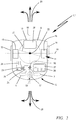
- Fig. 2 is schematically shown in plan view of a harrow 1.1, which is designed as a lawn mower 10.
- the illustration of the autonomously operating, self-propelled lawn mower 10 is exemplary.
- the tillage device 1.1 can also be designed as a scarifier, sweeper, vacuum cleaner, autonomously driving ride-on mower or the like tillage implement.
- the mower 10 shown by way of example consists essentially of a chassis with rear drive wheels 13 and 14 and a drive 11.
- the drive 11 consists of two independently controllable electric motors.
- a particular self-steering third wheel 17 is provided in the front region 12 of the housing 9 of the harrow 1.1 .
- the third wheel 17 is preferably located on a longitudinal central axis 18 of the housing 9 of the lawnmower 10.
- the formation of a chassis with four wheels may be appropriate.
- the drive wheels 13, 14 of the tillage device 1.1 shown rotate about a common drive shaft 19.
- the drive shaft 19 is - in plan view of the Lawnmower 10 after Fig. 2 - In particular at right angles to the longitudinal center axis 18 of the housing 9.
- For a straight ahead drive wheels 13 and 14 are to drive synchronously via their electric drive motors 15 and 16.
- the drive wheels 13, 14 are driven by their drive motors 15, 16 with, for example, different speeds.
- the harrow 1.1 in any desired direction of travel 20 according to the arrows shown to move forward or backward.
- the working tool 21 is a cutting blade rotating about a vertical axis of rotation 22.
- control of the electric drive motors 15 and 16 via a control unit 23 which is connected via schematically indicated electrical lines 29 to the electric drive motors 15 and 16.
- the wire signal 41 sent on the wire 43 of the wire loop 2 of the edge boundary is received in receiver coils 6 and 7 of the tillage device 1.1.
- the receiving coils 6 and 7 are in the front region 12 of the housing 9 each on one side of the longitudinal central axis 18 of the harrow 1.1.
- the received signals induced in the receiving coils 6 and 7 due to the transmitted wire signals 41 are fed to a common evaluation unit 24, which is connected to the control unit 23.
- the control unit 23 further comprises a memory 25 for an operating variable, which is useful for the operation of the tillage device 1.1.
- Such an operating variable may be, for example, the start time of the operation, the duration of the operation, the cutting height (when trained as a lawnmower), the route to a charging station, a mowing schedule as a weekly schedule, or the like operating variable.
- an input field 26 is shown, which advantageously has a screen 27 and input keys. It may be expedient to design the screen as a touch screen, so that input keys can be omitted.
- Each tillage device 1.1, 1.2 may further comprise a further receiver 50, which receives radio signals or infrared signals of a station transmitter 51.
- a station transmitter 51 may be provided, for example, at the base station 8 of the tillage system S, as in FIG Fig. 1 shown.
- the station transmitter 51 sends signals to the receiver 50 of the tillage implement 1.1.
- This wireless communication connection between the station transmitter 51 and the receiver 50 on the harrow 1.1 is advantageously designed as a radio link or the like. Possible radio links can be WLAN connections, Bluetooth connections, GSM connections, NFC connections or similar wireless connections.
- the station transmitter and the receiver are designed such that a transmission and reception of data is possible in both directions.
- the electrical supply of the control unit 23 and all its components, the electrical supply of the electric drive 11 and the electrical supply of the receiver 50 is ensured by an on-board battery 28 of the tillage device 1.1.
- the battery 28 is preferably inserted into the housing 9 of the tillage device 1.1.
- the tillage devices 1.1 and 1.2 are moved independently of one another in the work area A to be processed by corresponding activation of the drive motors 15 and 16.
- Each individual tillage implement 1.1 and 1.2 operates autonomously according to the information stored in its memory 25 operating variables.
- a coupling finger 52 may be provided, which enters into a corresponding coupling bushing 53 of the soil cultivation device 1.1 and establishes an electrical connection for charging the onboard battery 28.
- the wire signal 41 sent by the transmitting unit 32 is received electrically in the receiving unit 31 via the connection to the terminal ends 3 and 4.
- the wire signal 41 sent on the wire 43 varies in amplitude and waveform due to the geometric and electrical properties of the wire 43. Both the ohmic resistance of the wire 43 and the inductive and capacitive properties of a threaded wire loop 2 affect the wire signal 41 Signal distortions due to interference occur.
- the transmitted wire signal 41 from the tillage equipment 1.1, 1.2 over the entire length of the wire 43 of the deckle also with distance from the wire 43 is safe to receive.
- the received wire signal 42 should despite line losses on the wire loop 2 have an amplitude and / or waveform that ensures error-free control of the tillage equipment 1.1 and 1.2 throughout the work area.
- the signal conditioning device 30 compares the received wire signal 42 with a predetermined desired signal 40, which the signal conditioning device 30 expediently provided via a memory 35 is.
- the predetermined desired signal 40 may be a signal which satisfies legal requirements and is generally permissible on the wire 43 of the boundary. If the signal processing device 30 detects deviations from the predetermined setpoint signal 40, control commands are passed on via a line connection 34 to the transmitting unit 32, by means of which the wire signal 41 to be transmitted is changed in its amplitude I, its frequency, its signal form or similar signal variables.
- the transmitted wire signal 41 is modified according to the control commands and sent on the wire loop 2.
- the transmitted wire signal 41 is electrically tapped in the receiving unit 31 from the terminal ends 3, 4 of the wire loop 2 and received again.
- the received wire signal 42 of the signal conditioning device 30 is provided and compared by this with the predetermined desired signal 40. If further deviations from the setpoint signal 40 are detected, variables of the signal (amplitude, signal shape, time characteristic) are again changed and the wire signal 41 modified in this way is sent again via the connection ends 3, 4 of the wire 43 of the wire loop 2.
- the transmitting unit 32, the wire 43 of the wire loop 2, the receiving unit 31 and the signal processing device 30 form a control loop, in particular a closed loop.
- the adaptation of the transmitted wire signal 41 takes place until the received wire signal 42 approaches the predefined setpoint signal 40, preferably corresponds to the setpoint signal 40. It should be emphasized that the transmitted wire signal 41 and the predetermined target signal 40 may be formed differently in the amplitude I and / or the signal shape.
Landscapes
- Engineering & Computer Science (AREA)
- Physics & Mathematics (AREA)
- Remote Sensing (AREA)
- Automation & Control Theory (AREA)
- General Physics & Mathematics (AREA)
- Aviation & Aerospace Engineering (AREA)
- Radar, Positioning & Navigation (AREA)
- Environmental Sciences (AREA)
- Life Sciences & Earth Sciences (AREA)
- Signal Processing (AREA)
- Computer Networks & Wireless Communication (AREA)
- Electromagnetism (AREA)
- Computing Systems (AREA)
- Mathematical Physics (AREA)
- Theoretical Computer Science (AREA)
- Control Of Position, Course, Altitude, Or Attitude Of Moving Bodies (AREA)
- Guiding Agricultural Machines (AREA)
- Agricultural Machines (AREA)
Priority Applications (3)
| Application Number | Priority Date | Filing Date | Title |
|---|---|---|---|
| EP17400031.5A EP3412131B1 (fr) | 2017-06-09 | 2017-06-09 | Système de traitement de sol comprenant une adaptation de signal |
| US15/997,346 US10820493B2 (en) | 2017-06-09 | 2018-06-04 | Ground working system with signal adaptation |
| CN201810586125.5A CN109039385A (zh) | 2017-06-09 | 2018-06-08 | 具有信号匹配的耕作系统 |
Applications Claiming Priority (1)
| Application Number | Priority Date | Filing Date | Title |
|---|---|---|---|
| EP17400031.5A EP3412131B1 (fr) | 2017-06-09 | 2017-06-09 | Système de traitement de sol comprenant une adaptation de signal |
Publications (2)
| Publication Number | Publication Date |
|---|---|
| EP3412131A1 true EP3412131A1 (fr) | 2018-12-12 |
| EP3412131B1 EP3412131B1 (fr) | 2020-11-11 |
Family
ID=59276668
Family Applications (1)
| Application Number | Title | Priority Date | Filing Date |
|---|---|---|---|
| EP17400031.5A Active EP3412131B1 (fr) | 2017-06-09 | 2017-06-09 | Système de traitement de sol comprenant une adaptation de signal |
Country Status (3)
| Country | Link |
|---|---|
| US (1) | US10820493B2 (fr) |
| EP (1) | EP3412131B1 (fr) |
| CN (1) | CN109039385A (fr) |
Cited By (1)
| Publication number | Priority date | Publication date | Assignee | Title |
|---|---|---|---|---|
| DE102019201692A1 (de) * | 2019-02-11 | 2020-08-13 | Zf Friedrichshafen Ag | Verfahren und System zur Begrenzung und Überwachung mindestens eines Arbeitsbereichs für zumindest ein autonom betriebenes Fahrzeug |
Families Citing this family (13)
| Publication number | Priority date | Publication date | Assignee | Title |
|---|---|---|---|---|
| EP3412133B1 (fr) | 2017-06-09 | 2022-09-14 | Andreas Stihl AG & Co. KG | Système de travail du sol comprenant au moins une station de charge |
| EP3412134B1 (fr) | 2017-06-09 | 2020-08-19 | Andreas Stihl AG & Co. KG | Système de traitement de sol comprenant un câble périphérique continu |
| EP3412135B1 (fr) | 2017-06-09 | 2022-09-14 | Andreas Stihl AG & Co. KG | Système de traitement de sol avec au moins une station de charge comprenant une liaison de données |
| EP3412132B1 (fr) | 2017-06-09 | 2021-05-12 | Andreas Stihl AG & Co. KG | Système de traitement de sol comprenant au moins une zone intensive |
| CN112438111B (zh) * | 2019-09-02 | 2021-12-28 | 深圳拓邦股份有限公司 | 一种割草机系统通信方法、割草机系统及割草机基站 |
| CN114679949B (zh) * | 2020-12-30 | 2024-03-15 | 南京泉峰科技有限公司 | 一种自驱动设备系统和充电站 |
| US12296694B2 (en) | 2021-03-10 | 2025-05-13 | Techtronic Cordless Gp | Lawnmowers |
| US12443180B2 (en) | 2021-11-10 | 2025-10-14 | Techtronic Cordless Gp | Robotic lawn mowers |
| AU2023200381A1 (en) | 2022-01-31 | 2023-08-17 | Techtronic Cordless Gp | Robotic garden tool |
| EP4270138A1 (fr) | 2022-04-28 | 2023-11-01 | Techtronic Cordless GP | Création d'une limite virtuelle pour un outil de jardin robotisé |
| US12472611B2 (en) | 2022-05-31 | 2025-11-18 | Techtronic Cordless Gp | Peg driver |
| EP4310621B1 (fr) | 2022-07-19 | 2025-02-12 | Techtronic Cordless GP | Dispositif d'affichage pour commander un outil robotique |
| AU2023206123A1 (en) | 2022-07-29 | 2024-02-15 | Techtronic Cordless Gp | Generation of a cryptography key for a robotic garden tool |
Citations (3)
| Publication number | Priority date | Publication date | Assignee | Title |
|---|---|---|---|---|
| EP1906205A1 (fr) * | 2006-09-29 | 2008-04-02 | F. Robotics Acquisitions Ltd. | Procédé et système de détermination de l'emplacement d'un véhicule |
| EP2667271A1 (fr) * | 2012-05-23 | 2013-11-27 | Honda Motor Co., Ltd. | Système sans pilote avec sélection du signal de démarcation |
| WO2014158060A1 (fr) * | 2013-02-20 | 2014-10-02 | Husqvarna Ab | Procédé et système d'outil de travail robotisé doté d'une station de charge et d'un fil de bornage |
Family Cites Families (34)
| Publication number | Priority date | Publication date | Assignee | Title |
|---|---|---|---|---|
| SE0201739D0 (sv) | 2002-06-07 | 2002-06-07 | Electrolux Ab | Elektroniskt avgränsningssystem |
| US7126475B2 (en) * | 2004-08-17 | 2006-10-24 | Ho Yun So | Electronic fence transmitter for self-adjusting the receiving distance |
| US8306659B2 (en) | 2006-12-06 | 2012-11-06 | F Robotics Acquisitions Ltd. | Autonomous robot |
| CN101607399A (zh) | 2008-06-19 | 2009-12-23 | 鸿富锦精密工业(深圳)有限公司 | 充电装置 |
| DE102009001900A1 (de) * | 2008-10-20 | 2010-04-22 | Robert Bosch Gmbh | Verfahren und System zur Arbeitsbereichserkennung eines mobilen Arbeitsgerätes |
| DE102009027396A1 (de) | 2009-07-01 | 2011-01-13 | Robert Bosch Gmbh | Autonome mobile Plattform zur Flächenbearbeitung und Verfahren zur Flächenbearbeitung |
| US20110153172A1 (en) | 2009-12-23 | 2011-06-23 | Noel Wayne Anderson | Area management |
| US8744626B2 (en) | 2010-05-27 | 2014-06-03 | Deere & Company | Managing autonomous machines across multiple areas |
| WO2012072024A1 (fr) | 2010-11-30 | 2012-06-07 | 苏州宝时得电动工具有限公司 | Dispositif de marche automatique, poste de charge, système de connexion et procédé de connexion |
| KR101188891B1 (ko) | 2010-12-16 | 2012-10-09 | (주)마이크로인피니티 | 이미지 도안용 잔디관리장치 |
| WO2012083589A1 (fr) | 2010-12-20 | 2012-06-28 | 苏州宝时得电动工具有限公司 | Dispositif de marche automatique, système d'accueil et procédé d'accueil s'y rapportant |
| DE102011083309A1 (de) * | 2011-09-23 | 2013-03-28 | Robert Bosch Gmbh | Autonomes Arbeitsgerät |
| JP2013192678A (ja) | 2012-03-19 | 2013-09-30 | Sharp Corp | ロボット装置、情報提供装置、情報提供システム及びプログラム |
| EP2656718B1 (fr) | 2012-04-24 | 2018-07-04 | Robert Bosch Gmbh | Appareil d'entretien du sol et appareil de station de charge associé |
| EP2741160B1 (fr) | 2012-12-07 | 2016-10-12 | Viking GmbH | Procédé de commande d'une tondeuse automobile |
| JP6105377B2 (ja) * | 2013-04-30 | 2017-03-29 | 株式会社クボタ | 作業機、及び、アプリケーションプログラム |
| DE202013101894U1 (de) | 2013-04-30 | 2014-08-07 | Al-Ko Kober Ag | Basisstation für und Mähsystem mit mehreren Mährobotern |
| US9573275B2 (en) | 2013-11-12 | 2017-02-21 | Husqvarna Ab | Navigation for a robotic working tool |
| CN203883787U (zh) * | 2014-05-14 | 2014-10-15 | 杭州菲沃机器人科技有限公司 | 一种智能割草机的电子篱笆电路 |
| US9375842B2 (en) | 2014-05-15 | 2016-06-28 | Irobot Corporation | Autonomous mobile robot confinement system |
| WO2016019902A1 (fr) | 2014-08-07 | 2016-02-11 | 苏州宝时得电动工具有限公司 | Station de recharge sans fil, tondeuse automatique et système de tonte automatique |
| EP4235596A3 (fr) | 2014-12-22 | 2023-10-04 | Husqvarna AB | Véhicule robot de détection de structure de gazon |
| US10405488B2 (en) | 2014-12-23 | 2019-09-10 | Husqvarna Ab | Zone control system for a robotic vehicle |
| SE538373C2 (en) | 2014-12-23 | 2016-05-31 | Husqvarna Ab | Improved navigation for a robotic lawnmower |
| KR102398329B1 (ko) | 2015-03-16 | 2022-05-16 | 엘지전자 주식회사 | 이동 로봇의 충전 장치 및 그 제어방법 |
| SE538868C2 (en) | 2015-05-04 | 2017-01-17 | Husqvarna Ab | Improved error detection and resetting of a robotic work tool |
| US10034421B2 (en) | 2015-07-24 | 2018-07-31 | Irobot Corporation | Controlling robotic lawnmowers |
| DE102015114568A1 (de) | 2015-09-01 | 2017-03-02 | Claas Selbstfahrende Erntemaschinen Gmbh | Verfahren zum Betreiben von landwirtschaftlichen Arbeitsmaschinen |
| GB2560868B (en) * | 2016-09-29 | 2023-02-15 | Mtd Products Inc | Demarcating system |
| US10952369B2 (en) | 2017-04-24 | 2021-03-23 | Kubota Corporation | Grass management system |
| EP3412135B1 (fr) | 2017-06-09 | 2022-09-14 | Andreas Stihl AG & Co. KG | Système de traitement de sol avec au moins une station de charge comprenant une liaison de données |
| EP3412134B1 (fr) | 2017-06-09 | 2020-08-19 | Andreas Stihl AG & Co. KG | Système de traitement de sol comprenant un câble périphérique continu |
| EP3412133B1 (fr) | 2017-06-09 | 2022-09-14 | Andreas Stihl AG & Co. KG | Système de travail du sol comprenant au moins une station de charge |
| EP3412132B1 (fr) | 2017-06-09 | 2021-05-12 | Andreas Stihl AG & Co. KG | Système de traitement de sol comprenant au moins une zone intensive |
-
2017
- 2017-06-09 EP EP17400031.5A patent/EP3412131B1/fr active Active
-
2018
- 2018-06-04 US US15/997,346 patent/US10820493B2/en active Active
- 2018-06-08 CN CN201810586125.5A patent/CN109039385A/zh active Pending
Patent Citations (3)
| Publication number | Priority date | Publication date | Assignee | Title |
|---|---|---|---|---|
| EP1906205A1 (fr) * | 2006-09-29 | 2008-04-02 | F. Robotics Acquisitions Ltd. | Procédé et système de détermination de l'emplacement d'un véhicule |
| EP2667271A1 (fr) * | 2012-05-23 | 2013-11-27 | Honda Motor Co., Ltd. | Système sans pilote avec sélection du signal de démarcation |
| WO2014158060A1 (fr) * | 2013-02-20 | 2014-10-02 | Husqvarna Ab | Procédé et système d'outil de travail robotisé doté d'une station de charge et d'un fil de bornage |
Cited By (2)
| Publication number | Priority date | Publication date | Assignee | Title |
|---|---|---|---|---|
| DE102019201692A1 (de) * | 2019-02-11 | 2020-08-13 | Zf Friedrichshafen Ag | Verfahren und System zur Begrenzung und Überwachung mindestens eines Arbeitsbereichs für zumindest ein autonom betriebenes Fahrzeug |
| US12124273B2 (en) | 2019-02-11 | 2024-10-22 | Zf Friedrichshafen Ag | Method and system for delimiting and monitoring at least one working area for at least one autonomously operated vehicle |
Also Published As
| Publication number | Publication date |
|---|---|
| US20180352728A1 (en) | 2018-12-13 |
| CN109039385A (zh) | 2018-12-18 |
| US10820493B2 (en) | 2020-11-03 |
| EP3412131B1 (fr) | 2020-11-11 |
Similar Documents
| Publication | Publication Date | Title |
|---|---|---|
| EP3412131B1 (fr) | Système de traitement de sol comprenant une adaptation de signal | |
| EP3412134B1 (fr) | Système de traitement de sol comprenant un câble périphérique continu | |
| EP3412133B1 (fr) | Système de travail du sol comprenant au moins une station de charge | |
| EP3412135B1 (fr) | Système de traitement de sol avec au moins une station de charge comprenant une liaison de données | |
| EP3412132B1 (fr) | Système de traitement de sol comprenant au moins une zone intensive | |
| EP3597470B1 (fr) | Procédé d'alimentation en énergie d'une moissonneuse entraînés par câble | |
| EP3392731B1 (fr) | Procédé de fonctionnement d'un système de vehicules autonomes de traitement des sols | |
| EP1977640B1 (fr) | Moissonneuse agricole automobile dotée d'un dispositif de transbordement réglable | |
| EP3251484B1 (fr) | Procede et dispositif destines au fonctionnement d'une machine agricole | |
| WO2011035839A2 (fr) | Système de robots mobiles avec station de base | |
| DE102014105820A1 (de) | Kombination aus einem Zugfahrzeug und einer davon gezogenen Erntemaschine | |
| EP3164276A1 (fr) | Dispositif et procédé de détection d'un angle de pivotement entre un véhicule et une remorque | |
| EP2436252B1 (fr) | Procédé de commande à soulever des râteaux rotatifs | |
| EP4245108A1 (fr) | Procédé d'optimisation d'itinéraire | |
| EP4245107A1 (fr) | Procédé d'optimisation d'itinéraire | |
| DE69305257T2 (de) | Navigationsverfahren und -vorrichtung für ein automatisch geführtes Fahrzeug | |
| DE102012220956A1 (de) | Erfassungssystem für ein automatisiertes Fahrzeug | |
| EP4118943A1 (fr) | Procédé de planification d'un itinéraire de traitement d'un champ d'un engin de travail agricole | |
| WO2018184857A1 (fr) | Procédé pour commander une machine agricole pendant l'andainage d'un produit à récolter sur une surface agricole et machine agricole | |
| EP4272531A1 (fr) | Machine agricole automotrice | |
| EP3072375B1 (fr) | Engin agricole avec une interface homme-machine et procede de fonctionnement associe | |
| US11778949B2 (en) | Mower combination with location based conveyor control | |
| EP3837956B1 (fr) | Combinaison de mécanisme de tonte | |
| EP4552455A1 (fr) | Système de planification d'itinéraire de machines agricoles autonomes | |
| DE102022107924A1 (de) | Verfahren zum Betreiben eines landwirtschaftlichen Maschinensystems und landwirtschaftliches Maschinensystem zum Bearbeiten einer landwirtschaftlichen Nutzfläche |
Legal Events
| Date | Code | Title | Description |
|---|---|---|---|
| PUAI | Public reference made under article 153(3) epc to a published international application that has entered the european phase |
Free format text: ORIGINAL CODE: 0009012 |
|
| STAA | Information on the status of an ep patent application or granted ep patent |
Free format text: STATUS: THE APPLICATION HAS BEEN PUBLISHED |
|
| AK | Designated contracting states |
Kind code of ref document: A1 Designated state(s): AL AT BE BG CH CY CZ DE DK EE ES FI FR GB GR HR HU IE IS IT LI LT LU LV MC MK MT NL NO PL PT RO RS SE SI SK SM TR |
|
| AX | Request for extension of the european patent |
Extension state: BA ME |
|
| STAA | Information on the status of an ep patent application or granted ep patent |
Free format text: STATUS: REQUEST FOR EXAMINATION WAS MADE |
|
| 17P | Request for examination filed |
Effective date: 20190611 |
|
| RBV | Designated contracting states (corrected) |
Designated state(s): AL AT BE BG CH CY CZ DE DK EE ES FI FR GB GR HR HU IE IS IT LI LT LU LV MC MK MT NL NO PL PT RO RS SE SI SK SM TR |
|
| STAA | Information on the status of an ep patent application or granted ep patent |
Free format text: STATUS: EXAMINATION IS IN PROGRESS |
|
| 17Q | First examination report despatched |
Effective date: 20191014 |
|
| GRAP | Despatch of communication of intention to grant a patent |
Free format text: ORIGINAL CODE: EPIDOSNIGR1 |
|
| STAA | Information on the status of an ep patent application or granted ep patent |
Free format text: STATUS: GRANT OF PATENT IS INTENDED |
|
| INTG | Intention to grant announced |
Effective date: 20200612 |
|
| GRAS | Grant fee paid |
Free format text: ORIGINAL CODE: EPIDOSNIGR3 |
|
| GRAA | (expected) grant |
Free format text: ORIGINAL CODE: 0009210 |
|
| STAA | Information on the status of an ep patent application or granted ep patent |
Free format text: STATUS: THE PATENT HAS BEEN GRANTED |
|
| AK | Designated contracting states |
Kind code of ref document: B1 Designated state(s): AL AT BE BG CH CY CZ DE DK EE ES FI FR GB GR HR HU IE IS IT LI LT LU LV MC MK MT NL NO PL PT RO RS SE SI SK SM TR |
|
| REG | Reference to a national code |
Ref country code: GB Ref legal event code: FG4D Free format text: NOT ENGLISH |
|
| REG | Reference to a national code |
Ref country code: CH Ref legal event code: EP |
|
| REG | Reference to a national code |
Ref country code: AT Ref legal event code: REF Ref document number: 1332553 Country of ref document: AT Kind code of ref document: T Effective date: 20201115 |
|
| REG | Reference to a national code |
Ref country code: DE Ref legal event code: R096 Ref document number: 502017008143 Country of ref document: DE |
|
| REG | Reference to a national code |
Ref country code: IE Ref legal event code: FG4D Free format text: LANGUAGE OF EP DOCUMENT: GERMAN |
|
| REG | Reference to a national code |
Ref country code: SE Ref legal event code: TRGR |
|
| REG | Reference to a national code |
Ref country code: NL Ref legal event code: MP Effective date: 20201111 |
|
| PG25 | Lapsed in a contracting state [announced via postgrant information from national office to epo] |
Ref country code: GR Free format text: LAPSE BECAUSE OF FAILURE TO SUBMIT A TRANSLATION OF THE DESCRIPTION OR TO PAY THE FEE WITHIN THE PRESCRIBED TIME-LIMIT Effective date: 20210212 Ref country code: FI Free format text: LAPSE BECAUSE OF FAILURE TO SUBMIT A TRANSLATION OF THE DESCRIPTION OR TO PAY THE FEE WITHIN THE PRESCRIBED TIME-LIMIT Effective date: 20201111 Ref country code: NO Free format text: LAPSE BECAUSE OF FAILURE TO SUBMIT A TRANSLATION OF THE DESCRIPTION OR TO PAY THE FEE WITHIN THE PRESCRIBED TIME-LIMIT Effective date: 20210211 Ref country code: RS Free format text: LAPSE BECAUSE OF FAILURE TO SUBMIT A TRANSLATION OF THE DESCRIPTION OR TO PAY THE FEE WITHIN THE PRESCRIBED TIME-LIMIT Effective date: 20201111 Ref country code: PT Free format text: LAPSE BECAUSE OF FAILURE TO SUBMIT A TRANSLATION OF THE DESCRIPTION OR TO PAY THE FEE WITHIN THE PRESCRIBED TIME-LIMIT Effective date: 20210311 |
|
| PG25 | Lapsed in a contracting state [announced via postgrant information from national office to epo] |
Ref country code: BG Free format text: LAPSE BECAUSE OF FAILURE TO SUBMIT A TRANSLATION OF THE DESCRIPTION OR TO PAY THE FEE WITHIN THE PRESCRIBED TIME-LIMIT Effective date: 20210211 Ref country code: PL Free format text: LAPSE BECAUSE OF FAILURE TO SUBMIT A TRANSLATION OF THE DESCRIPTION OR TO PAY THE FEE WITHIN THE PRESCRIBED TIME-LIMIT Effective date: 20201111 Ref country code: LV Free format text: LAPSE BECAUSE OF FAILURE TO SUBMIT A TRANSLATION OF THE DESCRIPTION OR TO PAY THE FEE WITHIN THE PRESCRIBED TIME-LIMIT Effective date: 20201111 Ref country code: IS Free format text: LAPSE BECAUSE OF FAILURE TO SUBMIT A TRANSLATION OF THE DESCRIPTION OR TO PAY THE FEE WITHIN THE PRESCRIBED TIME-LIMIT Effective date: 20210311 |
|
| REG | Reference to a national code |
Ref country code: LT Ref legal event code: MG9D |
|
| PG25 | Lapsed in a contracting state [announced via postgrant information from national office to epo] |
Ref country code: HR Free format text: LAPSE BECAUSE OF FAILURE TO SUBMIT A TRANSLATION OF THE DESCRIPTION OR TO PAY THE FEE WITHIN THE PRESCRIBED TIME-LIMIT Effective date: 20201111 |
|
| PG25 | Lapsed in a contracting state [announced via postgrant information from national office to epo] |
Ref country code: SK Free format text: LAPSE BECAUSE OF FAILURE TO SUBMIT A TRANSLATION OF THE DESCRIPTION OR TO PAY THE FEE WITHIN THE PRESCRIBED TIME-LIMIT Effective date: 20201111 Ref country code: RO Free format text: LAPSE BECAUSE OF FAILURE TO SUBMIT A TRANSLATION OF THE DESCRIPTION OR TO PAY THE FEE WITHIN THE PRESCRIBED TIME-LIMIT Effective date: 20201111 Ref country code: SM Free format text: LAPSE BECAUSE OF FAILURE TO SUBMIT A TRANSLATION OF THE DESCRIPTION OR TO PAY THE FEE WITHIN THE PRESCRIBED TIME-LIMIT Effective date: 20201111 Ref country code: EE Free format text: LAPSE BECAUSE OF FAILURE TO SUBMIT A TRANSLATION OF THE DESCRIPTION OR TO PAY THE FEE WITHIN THE PRESCRIBED TIME-LIMIT Effective date: 20201111 Ref country code: CZ Free format text: LAPSE BECAUSE OF FAILURE TO SUBMIT A TRANSLATION OF THE DESCRIPTION OR TO PAY THE FEE WITHIN THE PRESCRIBED TIME-LIMIT Effective date: 20201111 Ref country code: LT Free format text: LAPSE BECAUSE OF FAILURE TO SUBMIT A TRANSLATION OF THE DESCRIPTION OR TO PAY THE FEE WITHIN THE PRESCRIBED TIME-LIMIT Effective date: 20201111 |
|
| REG | Reference to a national code |
Ref country code: DE Ref legal event code: R097 Ref document number: 502017008143 Country of ref document: DE |
|
| PG25 | Lapsed in a contracting state [announced via postgrant information from national office to epo] |
Ref country code: DK Free format text: LAPSE BECAUSE OF FAILURE TO SUBMIT A TRANSLATION OF THE DESCRIPTION OR TO PAY THE FEE WITHIN THE PRESCRIBED TIME-LIMIT Effective date: 20201111 |
|
| PLBE | No opposition filed within time limit |
Free format text: ORIGINAL CODE: 0009261 |
|
| STAA | Information on the status of an ep patent application or granted ep patent |
Free format text: STATUS: NO OPPOSITION FILED WITHIN TIME LIMIT |
|
| 26N | No opposition filed |
Effective date: 20210812 |
|
| PG25 | Lapsed in a contracting state [announced via postgrant information from national office to epo] |
Ref country code: NL Free format text: LAPSE BECAUSE OF FAILURE TO SUBMIT A TRANSLATION OF THE DESCRIPTION OR TO PAY THE FEE WITHIN THE PRESCRIBED TIME-LIMIT Effective date: 20201111 Ref country code: AL Free format text: LAPSE BECAUSE OF FAILURE TO SUBMIT A TRANSLATION OF THE DESCRIPTION OR TO PAY THE FEE WITHIN THE PRESCRIBED TIME-LIMIT Effective date: 20201111 Ref country code: IT Free format text: LAPSE BECAUSE OF FAILURE TO SUBMIT A TRANSLATION OF THE DESCRIPTION OR TO PAY THE FEE WITHIN THE PRESCRIBED TIME-LIMIT Effective date: 20201111 |
|
| PG25 | Lapsed in a contracting state [announced via postgrant information from national office to epo] |
Ref country code: SI Free format text: LAPSE BECAUSE OF FAILURE TO SUBMIT A TRANSLATION OF THE DESCRIPTION OR TO PAY THE FEE WITHIN THE PRESCRIBED TIME-LIMIT Effective date: 20201111 |
|
| PG25 | Lapsed in a contracting state [announced via postgrant information from national office to epo] |
Ref country code: ES Free format text: LAPSE BECAUSE OF FAILURE TO SUBMIT A TRANSLATION OF THE DESCRIPTION OR TO PAY THE FEE WITHIN THE PRESCRIBED TIME-LIMIT Effective date: 20201111 Ref country code: MC Free format text: LAPSE BECAUSE OF FAILURE TO SUBMIT A TRANSLATION OF THE DESCRIPTION OR TO PAY THE FEE WITHIN THE PRESCRIBED TIME-LIMIT Effective date: 20201111 |
|
| REG | Reference to a national code |
Ref country code: CH Ref legal event code: PL |
|
| GBPC | Gb: european patent ceased through non-payment of renewal fee |
Effective date: 20210609 |
|
| REG | Reference to a national code |
Ref country code: BE Ref legal event code: MM Effective date: 20210630 |
|
| PG25 | Lapsed in a contracting state [announced via postgrant information from national office to epo] |
Ref country code: LU Free format text: LAPSE BECAUSE OF NON-PAYMENT OF DUE FEES Effective date: 20210609 |
|
| PG25 | Lapsed in a contracting state [announced via postgrant information from national office to epo] |
Ref country code: LI Free format text: LAPSE BECAUSE OF NON-PAYMENT OF DUE FEES Effective date: 20210630 Ref country code: IE Free format text: LAPSE BECAUSE OF NON-PAYMENT OF DUE FEES Effective date: 20210609 Ref country code: GB Free format text: LAPSE BECAUSE OF NON-PAYMENT OF DUE FEES Effective date: 20210609 Ref country code: CH Free format text: LAPSE BECAUSE OF NON-PAYMENT OF DUE FEES Effective date: 20210630 |
|
| PG25 | Lapsed in a contracting state [announced via postgrant information from national office to epo] |
Ref country code: IS Free format text: LAPSE BECAUSE OF FAILURE TO SUBMIT A TRANSLATION OF THE DESCRIPTION OR TO PAY THE FEE WITHIN THE PRESCRIBED TIME-LIMIT Effective date: 20210311 |
|
| PG25 | Lapsed in a contracting state [announced via postgrant information from national office to epo] |
Ref country code: BE Free format text: LAPSE BECAUSE OF NON-PAYMENT OF DUE FEES Effective date: 20210630 |
|
| PG25 | Lapsed in a contracting state [announced via postgrant information from national office to epo] |
Ref country code: CY Free format text: LAPSE BECAUSE OF FAILURE TO SUBMIT A TRANSLATION OF THE DESCRIPTION OR TO PAY THE FEE WITHIN THE PRESCRIBED TIME-LIMIT Effective date: 20201111 |
|
| PG25 | Lapsed in a contracting state [announced via postgrant information from national office to epo] |
Ref country code: HU Free format text: LAPSE BECAUSE OF FAILURE TO SUBMIT A TRANSLATION OF THE DESCRIPTION OR TO PAY THE FEE WITHIN THE PRESCRIBED TIME-LIMIT; INVALID AB INITIO Effective date: 20170609 |
|
| REG | Reference to a national code |
Ref country code: AT Ref legal event code: MM01 Ref document number: 1332553 Country of ref document: AT Kind code of ref document: T Effective date: 20220609 |
|
| PGFP | Annual fee paid to national office [announced via postgrant information from national office to epo] |
Ref country code: SE Payment date: 20230626 Year of fee payment: 7 |
|
| PG25 | Lapsed in a contracting state [announced via postgrant information from national office to epo] |
Ref country code: AT Free format text: LAPSE BECAUSE OF NON-PAYMENT OF DUE FEES Effective date: 20220609 |
|
| PG25 | Lapsed in a contracting state [announced via postgrant information from national office to epo] |
Ref country code: MK Free format text: LAPSE BECAUSE OF FAILURE TO SUBMIT A TRANSLATION OF THE DESCRIPTION OR TO PAY THE FEE WITHIN THE PRESCRIBED TIME-LIMIT Effective date: 20201111 |
|
| PG25 | Lapsed in a contracting state [announced via postgrant information from national office to epo] |
Ref country code: TR Free format text: LAPSE BECAUSE OF FAILURE TO SUBMIT A TRANSLATION OF THE DESCRIPTION OR TO PAY THE FEE WITHIN THE PRESCRIBED TIME-LIMIT Effective date: 20201111 |
|
| PG25 | Lapsed in a contracting state [announced via postgrant information from national office to epo] |
Ref country code: MT Free format text: LAPSE BECAUSE OF FAILURE TO SUBMIT A TRANSLATION OF THE DESCRIPTION OR TO PAY THE FEE WITHIN THE PRESCRIBED TIME-LIMIT Effective date: 20201111 |
|
| REG | Reference to a national code |
Ref country code: SE Ref legal event code: EUG |
|
| PGFP | Annual fee paid to national office [announced via postgrant information from national office to epo] |
Ref country code: DE Payment date: 20250626 Year of fee payment: 9 |
|
| PGFP | Annual fee paid to national office [announced via postgrant information from national office to epo] |
Ref country code: FR Payment date: 20250624 Year of fee payment: 9 |
|
| PG25 | Lapsed in a contracting state [announced via postgrant information from national office to epo] |
Ref country code: SE Free format text: LAPSE BECAUSE OF NON-PAYMENT OF DUE FEES Effective date: 20240610 |